Embed Size (px)
Citation preview

OWNERSMANUAL
ISP Stitching & Bindery ProductsA D i v i s i o n O f S a m u e l S t r a p p i n g S y s t e m s
Model B2000
ISP Stitching & Bindery Products
2
Stitch'n Fold
Introduction ....................................................... 3
Specifications ..................................................... 3
Safety ................................................................. 4
Assembly Drawing ............................................ 5
Installation .......................................................... 6
Preventive Maintenance ..................................... 6
Control Panel ..................................................... 7
Fuses .................................................................. 7
Operation & Setup ............................................ 8
Side Stitching ..................................................... 9
Corner Stitching................................................. 10
Adjustments ....................................................... 11
Clutch Shear Pin Replacement ......................... 13
Trouble Shooting ............................................... 14
Exploded Drawings & Parts Lists .................... 16
Electrical Schematic ........................................... 31
Tail Jog (Optional) ............................................ 32
Activated Clinch (Optional) .............................. 34
CONTENTS
3
ISP Stitching & Bindery ProductsA D i v i s i o n O f S a m u e l S t r a p p i n g S y s t e m s
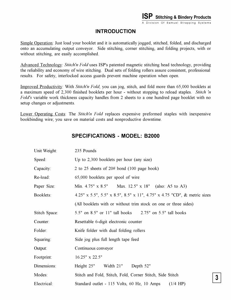
INTRODUCTION
Simple Operation: Just load your booklet and it is automatically jogged, stitched, folded, and dischargedonto an accumulating output conveyor. Side stitching, corner stitching, and folding projects, with orwithout stitching, are easily accomplished.
Advanced Technology: Stitch'n Fold uses ISP's patented magnetic stitching head technology, providingthe reliability and economy of wire stitching. Dual sets of folding rollers assure consistent, professionalresults. For safety, interlocked access guards prevent machine operation when open.
Improved Productivity: With Stitch'n Fold, you can jog, stitch, and fold more than 65,000 booklets ata maximum speed of 2,300 finished booklets per hour - without stopping to reload staples. Stitch 'nFold's variable work thickness capacity handles from 2 sheets to a one hundred page booklet with nosetup changes or adjustments.
Lower Operating Costs: The Stitch'n Fold replaces expensive preformed staples with inexpensivebookbinding wire; you save on material costs and nonproductive downtime.
SPECIFICATIONS - MODEL: B2000
Unit Weight: 235 Pounds
Speed: Up to 2,300 booklets per hour (any size)
Capacity: 2 to 25 sheets of 20# bond (100 page book)
Re-load: 65,000 booklets per spool of wire
Paper Size: Min. 4.75" x 8.5" Max. 12.5" x 18" (also: A5 to A3)
Booklets: 4.25" x 5.5", 5.5" x 8.5", 8.5" x 11", 4.75" x 4.75 "CD", & metric sizes
(All booklets with or without trim stock on one or three sides)
Stitch Space: 5.5" on 8.5" or 11" tall books 2.75" on 5.5" tall books
Counter: Resettable 6-digit electronic counter
Folder: Knife folder with dual folding rollers
Squaring: Side jog plus full length tape feed
Output: Continuous conveyor
Footprint: 16.25" x 22.5"
Dimensions: Height 25" Width 21" Depth 52"
Modes: Stitch and Fold, Stitch, Fold, Corner Stitch, Side Stitch
Electrical: Standard outlet - 115 Volts, 60 Hz, 10 Amps (1/4 HP)
4
Stitch'n FoldSAFETY
A. Front Guard: Blocks access to the stitchingheads and their point of operation. An elec-trical interlock keeps the machine turned offunless this hinged guard is closed. Do notstick your fingers under the front guard!
B. Top Guard: Blocks access to mechanism thatdrives the stitching heads. An electrical inter-lock keeps the machine turned off unless thisguard is closed. Do not stick your fingersunder the top guard!
C. Right Side Cover: Blocks access to mecha-nisms that can pinch or cut.
D. Left Side Cover: Blocks access to dangerouselectric voltage and mechanisms that can pinchor cut. Be sure to disconnect electrical powerbefore removing this cover.
E. Front Cover: Blocks access to dangerous elec-tric voltage and mechanisms that can pinch orcut. Be sure to disconnect electrical powerbefore removing this cover.
F. Rear Cover: Blocks access to low voltageconnections and mechanisms that can pinch orcut. Do not stick your fingers beyond thiscover!
G. Roller Guard: Blocks access to a pinch points.Do not stick your fingers beyond this cover!
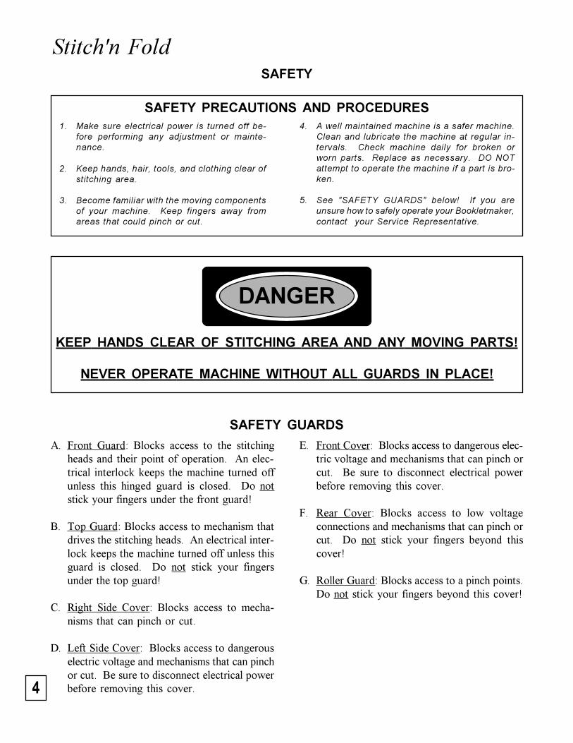
SAFETY GUARDS
1. Make sure electrical power is turned off be-fore performing any adjustment or mainte-nance.
2. Keep hands, hair, tools, and clothing clear ofstitching area.
3. Become familiar with the moving componentsof your machine. Keep fingers away fromareas that could pinch or cut.
4. A well maintained machine is a safer machine.Clean and lubricate the machine at regular in-tervals. Check machine daily for broken orworn parts. Replace as necessary. DO NOTattempt to operate the machine if a part is bro-ken.
5. See "SAFETY GUARDS" below! If you areunsure how to safely operate your Bookletmaker,contact your Service Representative.
SAFETY PRECAUTIONS AND PROCEDURES
DANGER
KEEP HANDS CLEAR OF STITCHING AREA AND ANY MOVING PARTS!
NEVER OPERATE MACHINE WITHOUT ALL GUARDS IN PLACE!
5
ISP Stitching & Bindery ProductsA D i v i s i o n O f S a m u e l S t r a p p i n g S y s t e m s
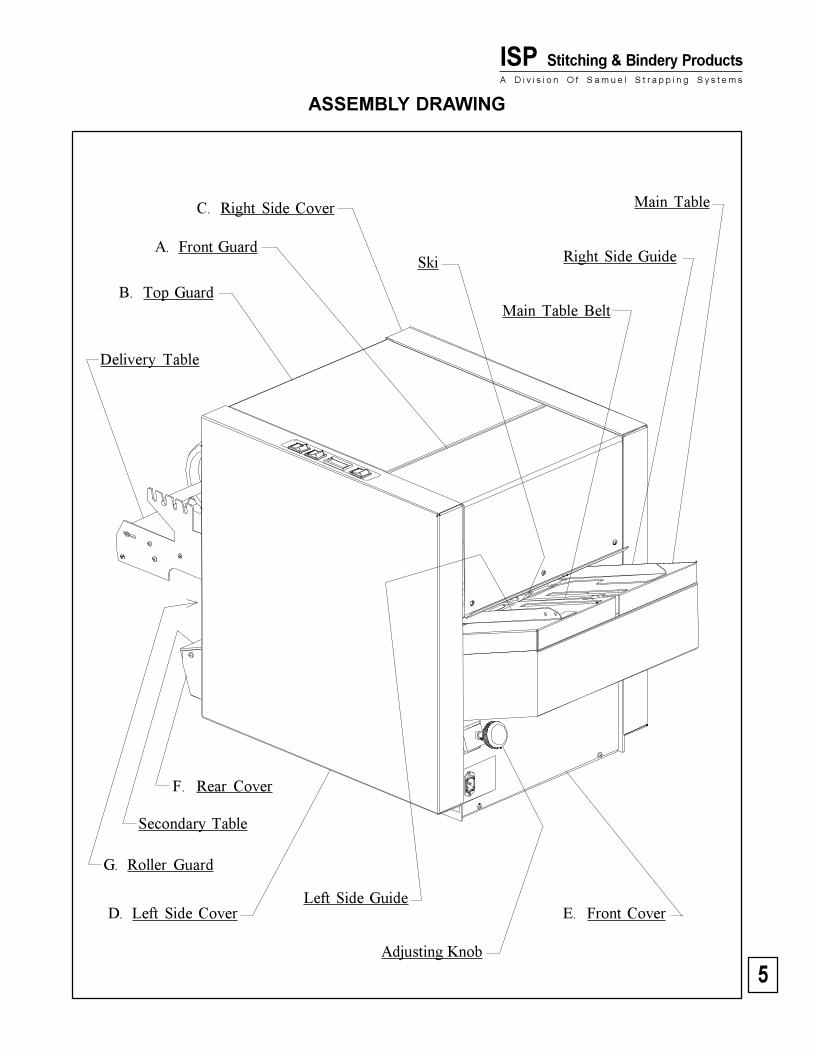
ASSEMBLY DRAWING
E. Front Cover
Secondary Table
Delivery Table
D. Left Side Cover
G. Roller Guard
B. Top Guard
Right Side Guide
C. Right Side Cover
A. Front Guard
Main Table Belt
Ski
Adjusting Knob
Left Side Guide
Main Table
F. Rear Cover
6
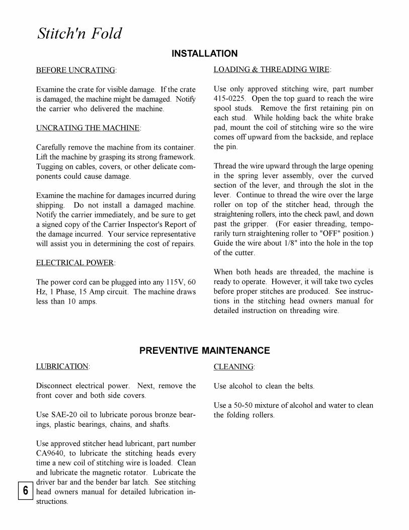
Stitch'n FoldINSTALLATION
PREVENTIVE MAINTENANCE
LUBRICATION:
Disconnect electrical power. Next, remove thefront cover and both side covers.
Use SAE-20 oil to lubricate porous bronze bear-ings, plastic bearings, chains, and shafts.
Use approved stitcher head lubricant, part numberCA9640, to lubricate the stitching heads everytime a new coil of stitching wire is loaded. Cleanand lubricate the magnetic rotator. Lubricate thedriver bar and the bender bar latch. See stitchinghead owners manual for detailed lubrication in-structions.
CLEANING:
Use alcohol to clean the belts.
Use a 50-50 mixture of alcohol and water to cleanthe folding rollers.
LOADING & THREADING WIRE:
Use only approved stitching wire, part number415-0225. Open the top guard to reach the wirespool studs. Remove the first retaining pin oneach stud. While holding back the white brakepad, mount the coil of stitching wire so the wirecomes off upward from the backside, and replacethe pin.
Thread the wire upward through the large openingin the spring lever assembly, over the curvedsection of the lever, and through the slot in thelever. Continue to thread the wire over the largeroller on top of the stitcher head, through thestraightening rollers, into the check pawl, and downpast the gripper. (For easier threading, tempo-rarily turn straightening roller to "OFF" position.)Guide the wire about 1/8" into the hole in the topof the cutter.
When both heads are threaded, the machine isready to operate. However, it will take two cyclesbefore proper stitches are produced. See instruc-tions in the stitching head owners manual fordetailed instruction on threading wire.
BEFORE UNCRATING:
Examine the crate for visible damage. If the crateis damaged, the machine might be damaged. Notifythe carrier who delivered the machine.
UNCRATING THE MACHINE:
Carefully remove the machine from its container.Lift the machine by grasping its strong framework.Tugging on cables, covers, or other delicate com-ponents could cause damage.
Examine the machine for damages incurred duringshipping. Do not install a damaged machine.Notify the carrier immediately, and be sure to geta signed copy of the Carrier Inspector's Report ofthe damage incurred. Your service representativewill assist you in determining the cost of repairs.
ELECTRICAL POWER:
The power cord can be plugged into any 115V, 60Hz, 1 Phase, 15 Amp circuit. The machine drawsless than 10 amps.
7
ISP Stitching & Bindery ProductsA D i v i s i o n O f S a m u e l S t r a p p i n g S y s t e m s
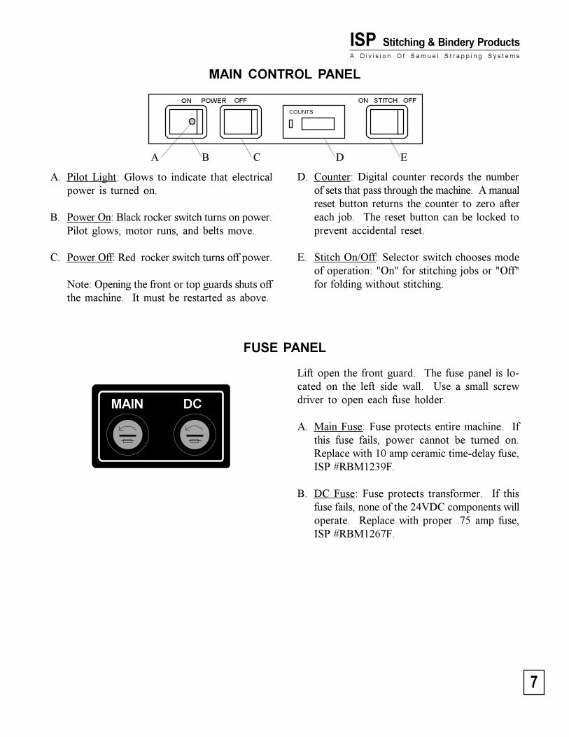
MAIN CONTROL PANEL
ON OFF
COUNTS
A. Pilot Light: Glows to indicate that electricalpower is turned on.
B. Power On: Black rocker switch turns on power.Pilot glows, motor runs, and belts move.
C. Power Off: Red rocker switch turns off power.
Note: Opening the front or top guards shuts offthe machine. It must be restarted as above.
FUSE PANEL
D. Counter: Digital counter records the numberof sets that pass through the machine. A manualreset button returns the counter to zero aftereach job. The reset button can be locked toprevent accidental reset.
E. Stitch On/Off: Selector switch chooses modeof operation: "On" for stitching jobs or "Off"for folding without stitching.
A B C D E
ON STITCH OFFPOWER
MAIN DC
Lift open the front guard. The fuse panel is lo-cated on the left side wall. Use a small screwdriver to open each fuse holder.
A. Main Fuse: Fuse protects entire machine. Ifthis fuse fails, power cannot be turned on.Replace with 10 amp ceramic time-delay fuse,ISP #RBM1239F.
B. DC Fuse: Fuse protects transformer. If thisfuse fails, none of the 24VDC components willoperate. Replace with proper .75 amp fuse,ISP #RBM1267F.
8
Stitch'n FoldOPERATION & SETUP
Bookletmaking & Basic AdjustmentsSee Following Sections For Corner Stitching Or Side Stitching
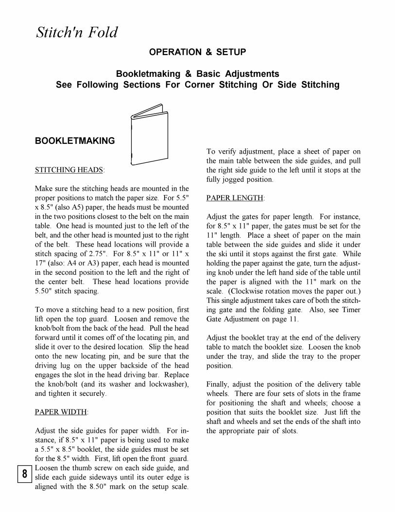
To verify adjustment, place a sheet of paper onthe main table between the side guides, and pullthe right side guide to the left until it stops at thefully jogged position.
PAPER LENGTH:
Adjust the gates for paper length. For instance,for 8.5" x 11" paper, the gates must be set for the11" length. Place a sheet of paper on the maintable between the side guides and slide it underthe ski until it stops against the first gate. Whileholding the paper against the gate, turn the adjust-ing knob under the left hand side of the table untilthe paper is aligned with the 11" mark on thescale. (Clockwise rotation moves the paper out.)This single adjustment takes care of both the stitch-ing gate and the folding gate. Also, see TimerGate Adjustment on page 11.
Adjust the booklet tray at the end of the deliverytable to match the booklet size. Loosen the knobunder the tray, and slide the tray to the properposition.
Finally, adjust the position of the delivery tablewheels. There are four sets of slots in the framefor positioning the shaft and wheels; choose aposition that suits the booklet size. Just lift theshaft and wheels and set the ends of the shaft intothe appropriate pair of slots.
BOOKLETMAKING
STITCHING HEADS:
Make sure the stitching heads are mounted in theproper positions to match the paper size. For 5.5"x 8.5" (also A5) paper, the heads must be mountedin the two positions closest to the belt on the maintable. One head is mounted just to the left of thebelt, and the other head is mounted just to the rightof the belt. These head locations will provide astitch spacing of 2.75". For 8.5" x 11" or 11" x17" (also: A4 or A3) paper, each head is mountedin the second position to the left and the right ofthe center belt. These head locations provide5.50" stitch spacing.
To move a stitching head to a new position, firstlift open the top guard. Loosen and remove theknob/bolt from the back of the head. Pull the headforward until it comes off of the locating pin, andslide it over to the desired location. Slip the headonto the new locating pin, and be sure that thedriving lug on the upper backside of the headengages the slot in the head driving bar. Replacethe knob/bolt (and its washer and lockwasher),and tighten it securely.
PAPER WIDTH:
Adjust the side guides for paper width. For in-stance, if 8.5" x 11" paper is being used to makea 5.5" x 8.5" booklet, the side guides must be setfor the 8.5" width. First, lift open the front guard.Loosen the thumb screw on each side guide, andslide each guide sideways until its outer edge isaligned with the 8.50" mark on the setup scale.
9
ISP Stitching & Bindery ProductsA D i v i s i o n O f S a m u e l S t r a p p i n g S y s t e m s
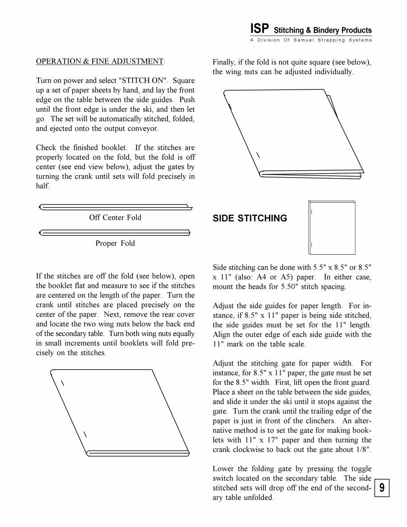
Off Center Fold
Proper Fold
SIDE STITCHING
Side stitching can be done with 5.5" x 8.5" or 8.5"x 11" (also: A4 or A5) paper. In either case,mount the heads for 5.50" stitch spacing.
Adjust the side guides for paper length. For in-stance, if 8.5" x 11" paper is being side stitched,the side guides must be set for the 11" length.Align the outer edge of each side guide with the11" mark on the table scale.
Adjust the stitching gate for paper width. Forinstance, for 8.5" x 11" paper, the gate must be setfor the 8.5" width. First, lift open the front guard.Place a sheet on the table between the side guides,and slide it under the ski until it stops against thegate. Turn the crank until the trailing edge of thepaper is just in front of the clinchers. An alter-native method is to set the gate for making book-lets with 11" x 17" paper and then turning thecrank clockwise to back out the gate about 1/8".
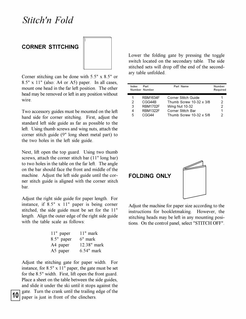
Lower the folding gate by pressing the toggleswitch located on the secondary table. The sidestitched sets will drop off the end of the second-ary table unfolded.
Finally, if the fold is not quite square (see below),the wing nuts can be adjusted individually.
OPERATION & FINE ADJUSTMENT:
Turn on power and select "STITCH ON". Squareup a set of paper sheets by hand, and lay the frontedge on the table between the side guides. Pushuntil the front edge is under the ski, and then letgo. The set will be automatically stitched, folded,and ejected onto the output conveyor.
Check the finished booklet. If the stitches areproperly located on the fold, but the fold is offcenter (see end view below), adjust the gates byturning the crank until sets will fold precisely inhalf.
If the stitches are off the fold (see below), openthe booklet flat and measure to see if the stitchesare centered on the length of the paper. Turn thecrank until stitches are placed precisely on thecenter of the paper. Next, remove the rear coverand locate the two wing nuts below the back endof the secondary table. Turn both wing nuts equallyin small increments until booklets will fold pre-cisely on the stitches.
10
Stitch'n Fold
Lower the folding gate by pressing the toggleswitch located on the secondary table. The sidestitched sets will drop off the end of the second-ary table unfolded.
CORNER STITCHING
Corner stitching can be done with 5.5" x 8.5" or8.5" x 11" (also: A4 or A5) paper. In all cases,mount one head in the far left position. The otherhead may be removed or left in any position withoutwire.
Two accessory guides must be mounted on the lefthand side for corner stitching. First, adjust thestandard left side guide as far as possible to theleft. Using thumb screws and wing nuts, attach thecorner stitch guide (9" long sheet metal part) tothe two holes in the left side guide.
Next, lift open the top guard. Using two thumbscrews, attach the corner stitch bar (11" long bar)to two holes in the table on the far left. The angleon the bar should face the front and middle of themachine. Adjust the left side guide until the cor-ner stitch guide is aligned with the corner stitchbar.
Adjust the right side guide for paper length. Forinstance, if 8.5" x 11" paper is being cornerstitched, the side guide must be set for the 11"length. Align the outer edge of the right side guidewith the table scale as follows:
11" paper 11" mark8.5" paper 6" markA4 paper 12.38" markA5 paper 6.54" mark
Adjust the stitching gate for paper width. Forinstance, for 8.5" x 11" paper, the gate must be setfor the 8.5" width. First, lift open the front guard.Place a sheet on the table between the side guides,and slide it under the ski until it stops against thegate. Turn the crank until the trailing edge of thepaper is just in front of the clinchers.
Index Part Part Name NumberNumber Number Required
1 RBM1634F Corner Stitch Guide 12 CGG44B Thumb Screw 10-32 x 3/8 23 RBM1702F Wing Nut 10-32 24 RBM1322F Corner Stitch Bar 15 CGG44 Thumb Screw 10-32 x 5/8 2
FOLDING ONLY
Adjust the machine for paper size according to theinstructions for bookletmaking. However, thestitching heads may be left in any mounting posi-tions. On the control panel, select "STITCH OFF".
11
ISP Stitching & Bindery ProductsA D i v i s i o n O f S a m u e l S t r a p p i n g S y s t e m s
ADJUSTMENTS
STITCHING CLUTCH
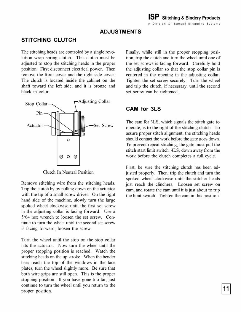
The stitching heads are controled by a single revo-lution wrap spring clutch. This clutch must beadjusted to stop the stitching heads in the properposition. First disconnect electrical power. Thenremove the front cover and the right side cover.The clutch is located inside the cabinet on theshaft toward the left side, and it is bronze andblack in color.
Stop Collar
Actuator
Pin
Set Screw
Adjusting Collar
Clutch In Neutral Position
Remove stitching wire from the stitching heads.Trip the clutch by by pulling down on the actuatorwith the tip of a small screw driver. On the righthand side of the machine, slowly turn the largespoked wheel clockwise until the first set screwin the adjusting collar is facing forward. Use a5/64 hex wrench to loosen the set screw. Con-tinue to turn the wheel until the second set screwis facing forward; loosen the screw.
Turn the wheel until the stop on the stop collarhits the actuator. Now turn the wheel until theproper stopping position is reached. Watch thestitching heads on the up stroke. When the benderbars reach the top of the windows in the faceplates, turn the wheel slightly more. Be sure thatboth wire grips are still open. This is the properstopping position. If you have gone too far, justcontinue to turn the wheel until you return to theproper position.
Finally, while still in the proper stopping posi-tion, trip the clutch and turn the wheel until one ofthe set screws is facing forward. Carefully holdthe adjusting collar so that the stop collar pin iscentered in the opening in the adjusting collar.Tighten the set screw securely. Turn the wheeland trip the clutch, if necessary, until the secondset screw can be tightened.
CAM for 3LS
The cam for 3LS, which signals the stitch gate tooperate, is to the right of the stitching clutch. Toassure proper stitch alignment, the stitching headsshould contact the work before the gate goes down.To prevent repeat stitching, the gate must pull thestitch start limit switch, 4LS, down away from thework before the clutch completes a full cycle.
First, be sure the stitching clutch has been ad-justed properly. Then, trip the clutch and turn thespoked wheel clockwise until the stitcher headsjust reach the clinchers. Loosen set screw oncam, and rotate the cam until it is just about to tripthe limit switch. Tighten the cam in this position.
12
Stitch'n FoldGATE TIMER
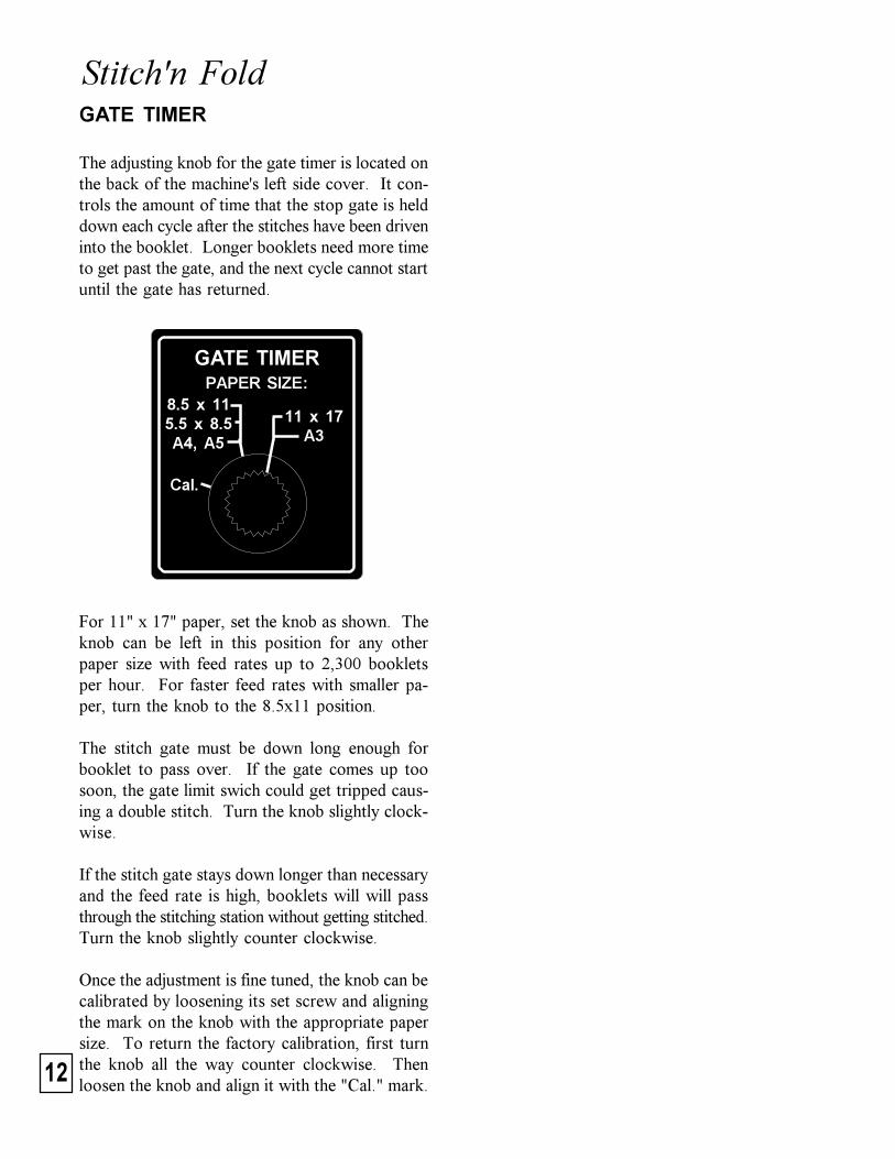
The adjusting knob for the gate timer is located onthe back of the machine's left side cover. It con-trols the amount of time that the stop gate is helddown each cycle after the stitches have been driveninto the booklet. Longer booklets need more timeto get past the gate, and the next cycle cannot startuntil the gate has returned.
For 11" x 17" paper, set the knob as shown. Theknob can be left in this position for any otherpaper size with feed rates up to 2,300 bookletsper hour. For faster feed rates with smaller pa-per, turn the knob to the 8.5x11 position.
The stitch gate must be down long enough forbooklet to pass over. If the gate comes up toosoon, the gate limit swich could get tripped caus-ing a double stitch. Turn the knob slightly clock-wise.
If the stitch gate stays down longer than necessaryand the feed rate is high, booklets will will passthrough the stitching station without getting stitched.Turn the knob slightly counter clockwise.
Once the adjustment is fine tuned, the knob can becalibrated by loosening its set screw and aligningthe mark on the knob with the appropriate papersize. To return the factory calibration, first turnthe knob all the way counter clockwise. Thenloosen the knob and align it with the "Cal." mark.
GATE TIMER
11 x 17A3
8.5 x 115.5 x 8.5A4, A5
Cal.
PAPER SIZE:
13
ISP Stitching & Bindery ProductsA D i v i s i o n O f S a m u e l S t r a p p i n g S y s t e m s
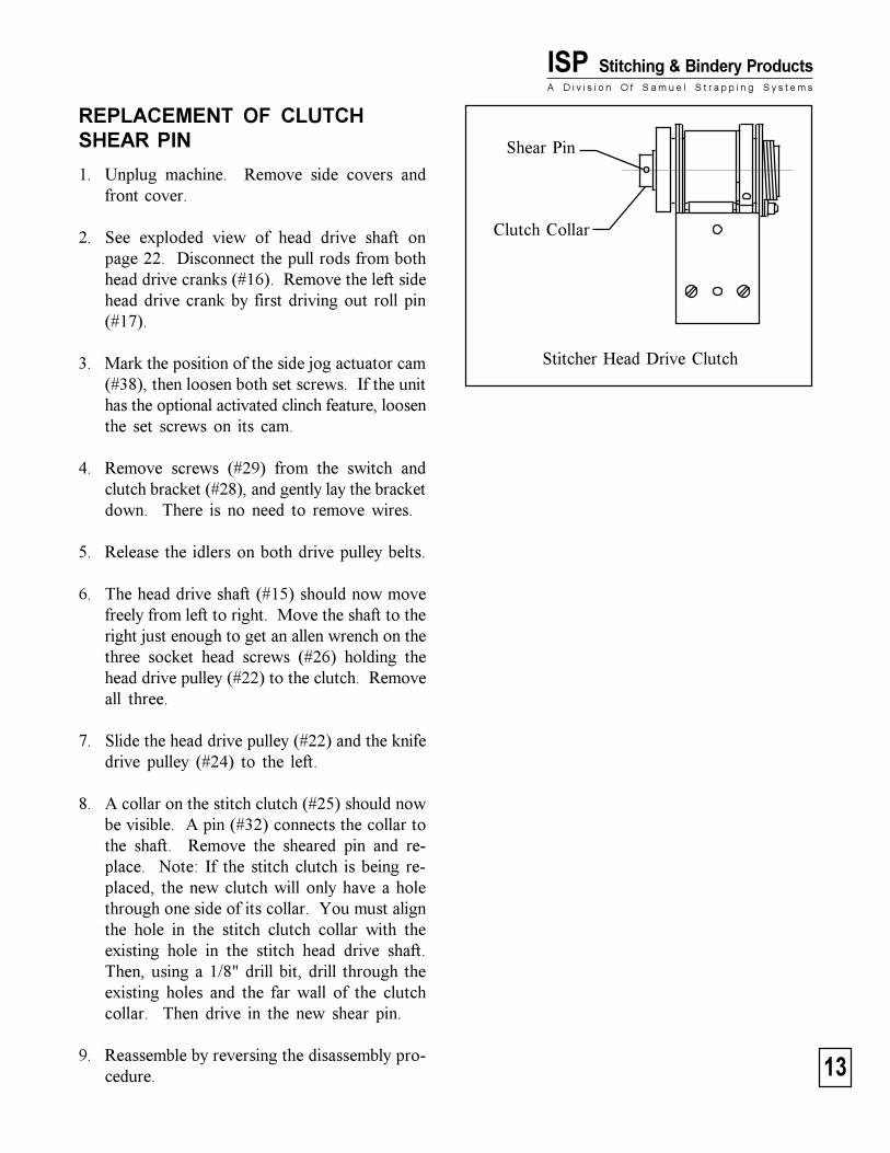
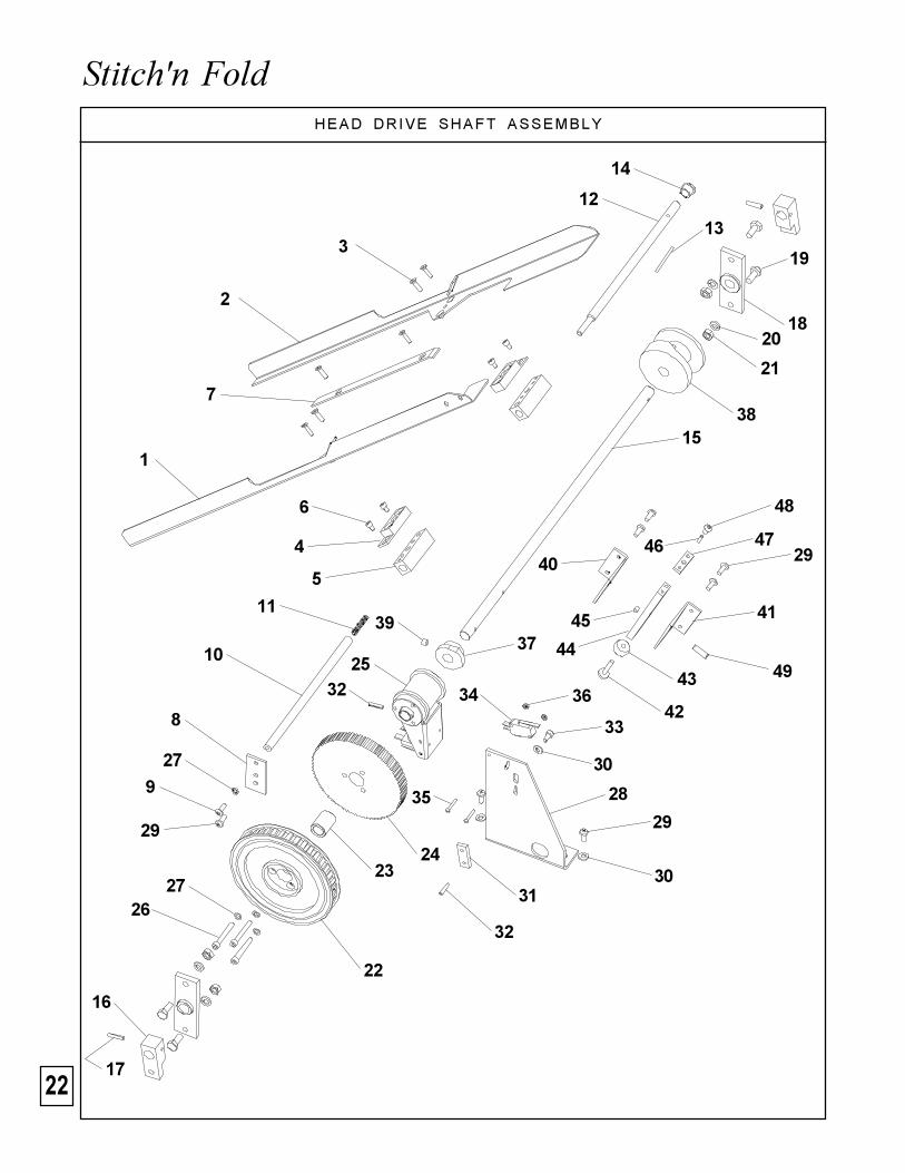
REPLACEMENT OF CLUTCHSHEAR PIN
1. Unplug machine. Remove side covers andfront cover.
2. See exploded view of head drive shaft onpage 22. Disconnect the pull rods from bothhead drive cranks (#16). Remove the left sidehead drive crank by first driving out roll pin(#17).
3. Mark the position of the side jog actuator cam(#38), then loosen both set screws. If the unithas the optional activated clinch feature, loosenthe set screws on its cam.
4. Remove screws (#29) from the switch andclutch bracket (#28), and gently lay the bracketdown. There is no need to remove wires.
5. Release the idlers on both drive pulley belts.
6. The head drive shaft (#15) should now movefreely from left to right. Move the shaft to theright just enough to get an allen wrench on thethree socket head screws (#26) holding thehead drive pulley (#22) to the clutch. Removeall three.
7. Slide the head drive pulley (#22) and the knifedrive pulley (#24) to the left.
8. A collar on the stitch clutch (#25) should nowbe visible. A pin (#32) connects the collar tothe shaft. Remove the sheared pin and re-place. Note: If the stitch clutch is being re-placed, the new clutch will only have a holethrough one side of its collar. You must alignthe hole in the stitch clutch collar with theexisting hole in the stitch head drive shaft.Then, using a 1/8" drill bit, drill through theexisting holes and the far wall of the clutchcollar. Then drive in the new shear pin.
9. Reassemble by reversing the disassembly pro-cedure.
Stitcher Head Drive Clutch
Clutch Collar
Shear Pin
14
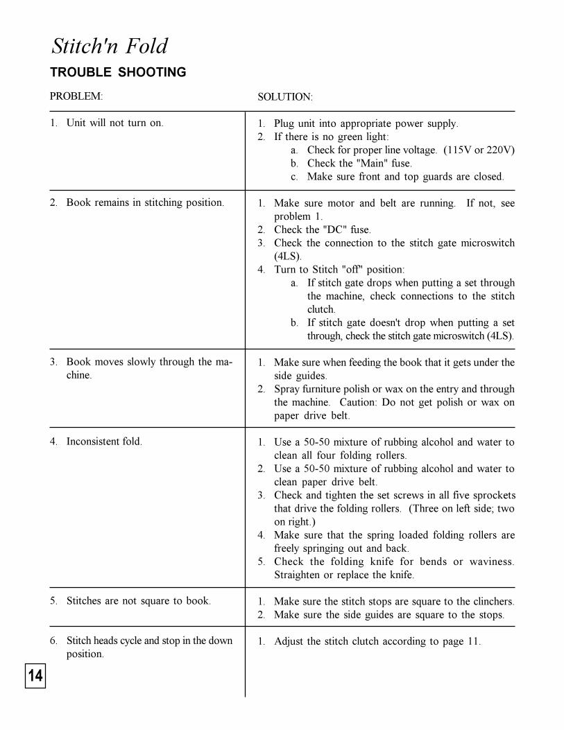
Stitch'n FoldTROUBLE SHOOTING
PROBLEM:
1. Unit will not turn on.
2. Book remains in stitching position.
3. Book moves slowly through the ma-chine.
4. Inconsistent fold.
5. Stitches are not square to book.
6. Stitch heads cycle and stop in the downposition.
SOLUTION:
1. Plug unit into appropriate power supply.2. If there is no green light:
a. Check for proper line voltage. (115V or 220V)b. Check the "Main" fuse.c. Make sure front and top guards are closed.
1. Make sure motor and belt are running. If not, seeproblem 1.
2. Check the "DC" fuse.3. Check the connection to the stitch gate microswitch
(4LS).4. Turn to Stitch "off" position:
a. If stitch gate drops when putting a set throughthe machine, check connections to the stitchclutch.
b. If stitch gate doesn't drop when putting a setthrough, check the stitch gate microswitch (4LS).
1. Make sure when feeding the book that it gets under theside guides.
2. Spray furniture polish or wax on the entry and throughthe machine. Caution: Do not get polish or wax onpaper drive belt.
1. Use a 50-50 mixture of rubbing alcohol and water toclean all four folding rollers.
2. Use a 50-50 mixture of rubbing alcohol and water toclean paper drive belt.
3. Check and tighten the set screws in all five sprocketsthat drive the folding rollers. (Three on left side; twoon right.)
4. Make sure that the spring loaded folding rollers arefreely springing out and back.
5. Check the folding knife for bends or waviness.Straighten or replace the knife.
1. Make sure the stitch stops are square to the clinchers.2. Make sure the side guides are square to the stops.
1. Adjust the stitch clutch according to page 11.
15
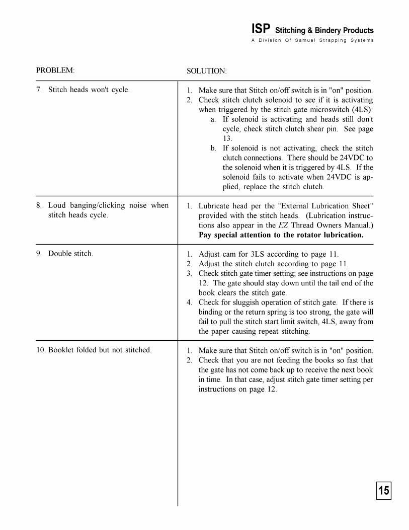
ISP Stitching & Bindery ProductsA D i v i s i o n O f S a m u e l S t r a p p i n g S y s t e m s
PROBLEM:
7. Stitch heads won't cycle.
8. Loud banging/clicking noise whenstitch heads cycle.
9. Double stitch.
10. Booklet folded but not stitched.
SOLUTION:
1. Make sure that Stitch on/off switch is in "on" position.2. Check stitch clutch solenoid to see if it is activating
when triggered by the stitch gate microswitch (4LS):a. If solenoid is activating and heads still don't
cycle, check stitch clutch shear pin. See page13.
b. If solenoid is not activating, check the stitchclutch connections. There should be 24VDC tothe solenoid when it is triggered by 4LS. If thesolenoid fails to activate when 24VDC is ap-plied, replace the stitch clutch.
1. Lubricate head per the "External Lubrication Sheet"provided with the stitch heads. (Lubrication instruc-tions also appear in the EZ Thread Owners Manual.)Pay special attention to the rotator lubrication.
1. Adjust cam for 3LS according to page 11.2. Adjust the stitch clutch according to page 11.3. Check stitch gate timer setting; see instructions on page
12. The gate should stay down until the tail end of thebook clears the stitch gate.
4. Check for sluggish operation of stitch gate. If there isbinding or the return spring is too strong, the gate willfail to pull the stitch start limit switch, 4LS, away fromthe paper causing repeat stitching.
1. Make sure that Stitch on/off switch is in "on" position.2. Check that you are not feeding the books so fast that
the gate has not come back up to receive the next bookin time. In that case, adjust stitch gate timer setting perinstructions on page 12.
16
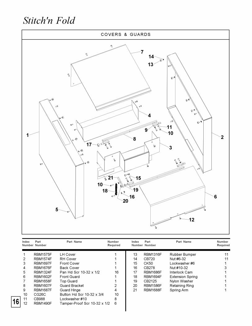
Stitch'n FoldCOVERS & GUARDS
Index Part Part Name NumberNumber Number Required
Index Part Part Name NumberNumber Number Required
13 RBM1316F Rubber Bumper 1114 CB720 Nut #6-32 1115 CK50 Lockwasher #6 116 CB278 Nut #10-32 317 RBM1686F Interlock Cam 118 RBM1694F Extension Spring 119 CB2125 Nylon Washer 120 RBM1586F Retaining Ring 121 RBM1688F Spring Arm 1
1 RBM1575F LH Cover 12 RBM1574F RH Cover 13 RBM1697F Front Cover 14 RBM1676F Back Cover 15 RBM1324F Pan Hd Scr 10-32 x 1/2 166 RBM1602F Front Guard 17 RBM1658F Top Guard 18 RBM1607F Guard Bracket 29 RBM1687F Guard Hinge 410 CG26C Button Hd Scr 10-32 x 3/4 1011 CB988 Lockwasher #10 812 RBM1490F Tamper-Proof Scr 10-32 x 1/2 6
21
3
4
5
6
7
8
91011
1018
12
14
13
15
16
17
19
20
21
17
ISP Stitching & Bindery ProductsA D i v i s i o n O f S a m u e l S t r a p p i n g S y s t e m s
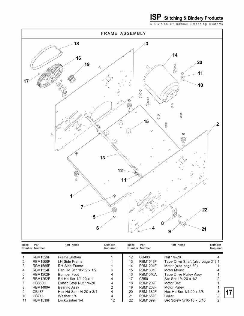
FRAME ASSEMBLY
Index Part Part Name NumberNumber Number Required
Index Part Part Name NumberNumber Number Required
12 CB493 Nut 1/4-20 413 RBM1543F Tape Drive Shaft (also page 21) 114 RBM1201F Motor (also page 30) 115 RBM1301F Motor Mount 416 RBM1046A Tape Drive Pulley Assy 117 CB59 Set Scr 1/4-20 x 1/2 218 RBM1209F Motor Belt 119 RBM1208F Motor Pulley 120 RBM1382F Hex Hd Scr 1/4-20 x 3/8 821 RBM1657F Collar 222 RBM1399F Set Screw 5/16-18 x 5/16 2
1 RBM1529F Frame Bottom 12 RBM1566F LH Side Frame 13 RBM1565F RH Side Frame 14 RBM1324F Pan Hd Scr 10-32 x 1/2 65 RBM1202F Bumper Foot 46 RBM1252F Rd Hd Scr 1/4-20 x 1 47 CB860C Elastic Stop Nut 1/4-20 48 RBM1480A Bearing Assy 29 CB487 Hex Hd Scr 1/4-20 x 3/4 410 CB718 Washer 1/4 411 RBM1519F Lockwasher 1/4 12
18
10
16
1
68
19
13
14
3
11
4
15 2
5
12
9
7
11
17
20
22
21
18
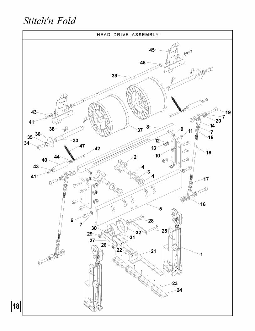
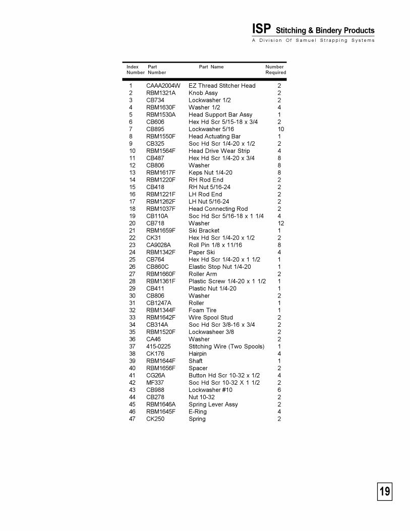
Stitch'n FoldHEAD DRIVE ASSEMBLY
1
4
2
34
5
67
8 9 11
10
1213
19
147
15
720
18
16
2122
2324
17
25
28
26
29 32
27
30
31
46
39
38
33
45
40
3635
34
37
44
47 42
43
41
43
41
19
ISP Stitching & Bindery ProductsA D i v i s i o n O f S a m u e l S t r a p p i n g S y s t e m s
Index Part Part Name NumberNumber Number Required
1 CAAA2004W EZ Thread Stitcher Head 22 RBM1321A Knob Assy 23 CB734 Lockwasher 1/2 24 RBM1630F Washer 1/2 45 RBM1530A Head Support Bar Assy 16 CB606 Hex Hd Scr 5/15-18 x 3/4 27 CB895 Lockwasher 5/16 108 RBM1550F Head Actuating Bar 19 CB325 Soc Hd Scr 1/4-20 x 1/2 210 RBM1564F Head Drive Wear Strip 411 CB487 Hex Hd Scr 1/4-20 x 3/4 812 CB806 Washer 813 RBM1617F Keps Nut 1/4-20 814 RBM1220F RH Rod End 215 CB418 RH Nut 5/16-24 216 RBM1221F LH Rod End 217 RBM1262F LH Nut 5/16-24 218 RBM1037F Head Connecting Rod 219 CB110A Soc Hd Scr 5/16-18 x 1 1/4 420 CB718 Washer 1221 RBM1659F Ski Bracket 122 CK31 Hex Hd Scr 1/4-20 x 1/2 223 CA9028A Roll Pin 1/8 x 11/16 824 RBM1342F Paper Ski 425 CB764 Hex Hd Scr 1/4-20 x 1 1/2 126 CB860C Elastic Stop Nut 1/4-20 127 RBM1660F Roller Arm 228 RBM1361F Plastic Screw 1/4-20 x 1 1/2 129 CB411 Plastic Nut 1/4-20 130 CB806 Washer 231 CB1247A Roller 132 RBM1344F Foam Tire 133 RBM1642F Wire Spool Stud 234 CB314A Soc Hd Scr 3/8-16 x 3/4 235 RBM1520F Lockwasheer 3/8 236 CA46 Washer 237 415-0225 Stitching Wire (Two Spools) 138 CK176 Hairpin 439 RBM1644F Shaft 140 RBM1656F Spacer 241 CG26A Button Hd Scr 10-32 x 1/2 442 MF337 Soc Hd Scr 10-32 X 1 1/2 243 CB988 Lockwasher #10 644 CB278 Nut 10-32 245 RBM1646A Spring Lever Assy 246 RBM1645F E-Ring 447 CK250 Spring 2
20
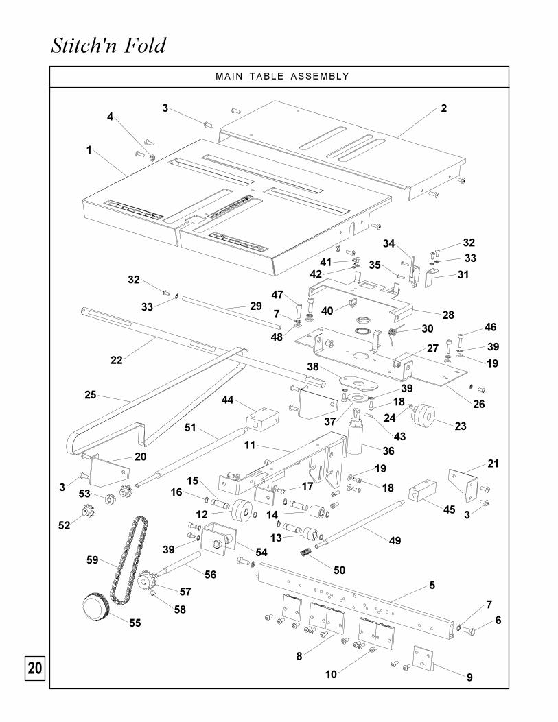
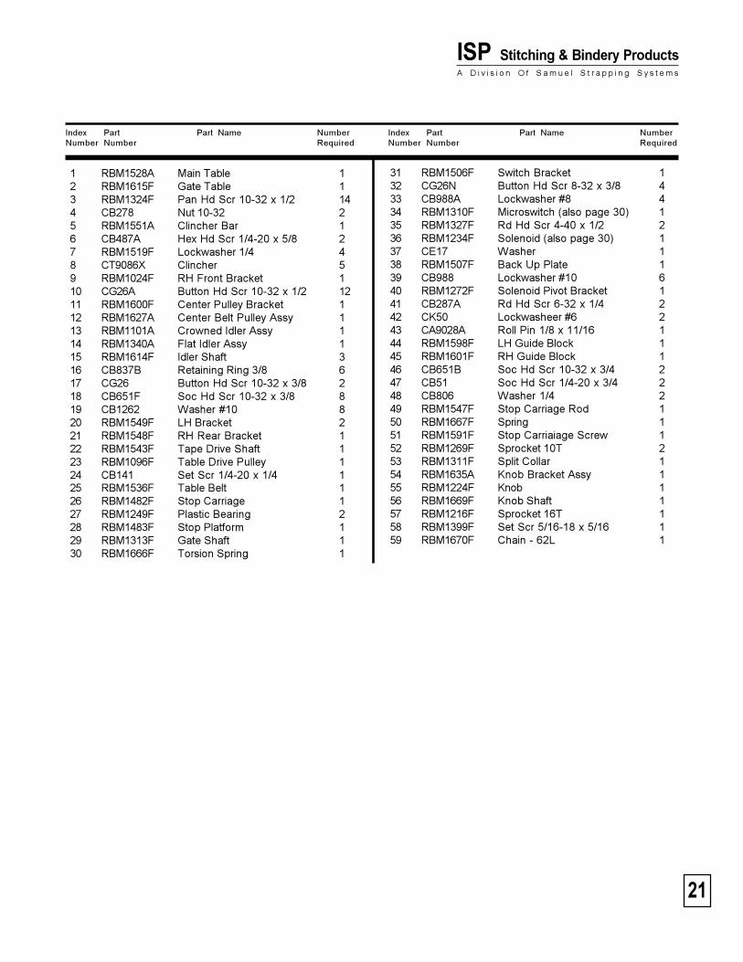
Stitch'n Fold MAIN TABLE ASSEMBLY
5
6
1
234
3
3
7
8
10
11
13
12
9
14
1516 17
19
18
2021
22
2423
25
27
26
2830
29
31
32
32
33
3334
35
36
37
38
3918
43
40
4142
44
45
49
50
51
52
53
54
46
39
19
47
7
48
5939
55
56
57
58
21
ISP Stitching & Bindery ProductsA D i v i s i o n O f S a m u e l S t r a p p i n g S y s t e m s
1 RBM1528A Main Table 12 RBM1615F Gate Table 13 RBM1324F Pan Hd Scr 10-32 x 1/2 144 CB278 Nut 10-32 25 RBM1551A Clincher Bar 16 CB487A Hex Hd Scr 1/4-20 x 5/8 27 RBM1519F Lockwasher 1/4 48 CT9086X Clincher 59 RBM1024F RH Front Bracket 110 CG26A Button Hd Scr 10-32 x 1/2 1211 RBM1600F Center Pulley Bracket 112 RBM1627A Center Belt Pulley Assy 113 RBM1101A Crowned Idler Assy 114 RBM1340A Flat Idler Assy 115 RBM1614F Idler Shaft 316 CB837B Retaining Ring 3/8 617 CG26 Button Hd Scr 10-32 x 3/8 218 CB651F Soc Hd Scr 10-32 x 3/8 819 CB1262 Washer #10 820 RBM1549F LH Bracket 221 RBM1548F RH Rear Bracket 122 RBM1543F Tape Drive Shaft 123 RBM1096F Table Drive Pulley 124 CB141 Set Scr 1/4-20 x 1/4 125 RBM1536F Table Belt 126 RBM1482F Stop Carriage 127 RBM1249F Plastic Bearing 228 RBM1483F Stop Platform 129 RBM1313F Gate Shaft 130 RBM1666F Torsion Spring 1
Index Part Part Name NumberNumber Number Required
Index Part Part Name NumberNumber Number Required
31 RBM1506F Switch Bracket 132 CG26N Button Hd Scr 8-32 x 3/8 433 CB988A Lockwasher #8 434 RBM1310F Microswitch (also page 30) 135 RBM1327F Rd Hd Scr 4-40 x 1/2 236 RBM1234F Solenoid (also page 30) 137 CE17 Washer 138 RBM1507F Back Up Plate 139 CB988 Lockwasher #10 640 RBM1272F Solenoid Pivot Bracket 141 CB287A Rd Hd Scr 6-32 x 1/4 242 CK50 Lockwasheer #6 243 CA9028A Roll Pin 1/8 x 11/16 144 RBM1598F LH Guide Block 145 RBM1601F RH Guide Block 146 CB651B Soc Hd Scr 10-32 x 3/4 247 CB51 Soc Hd Scr 1/4-20 x 3/4 248 CB806 Washer 1/4 249 RBM1547F Stop Carriage Rod 150 RBM1667F Spring 151 RBM1591F Stop Carriaiage Screw 152 RBM1269F Sprocket 10T 253 RBM1311F Split Collar 154 RBM1635A Knob Bracket Assy 155 RBM1224F Knob 156 RBM1669F Knob Shaft 157 RBM1216F Sprocket 16T 158 RBM1399F Set Scr 5/16-18 x 5/16 159 RBM1670F Chain - 62L 1
22
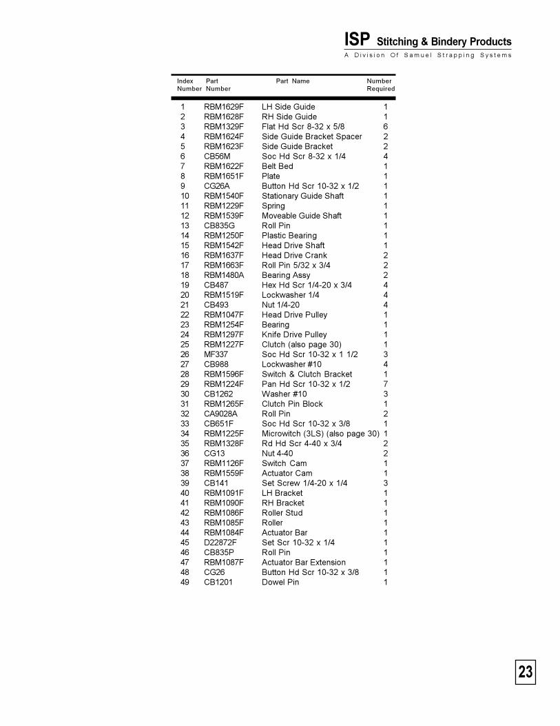
Stitch'n Fold HEAD DRIVE SHAFT ASSEMBLY
3
12
32
33
35
41
1
2
4
5
42
6
7
8
9
10
11
27
14
29
13
15
16
17
18
19
21
20
22
2324
26
25
28
29
303127
34 36
30
32
29
3739
40
43
44
45
46
48
47
49
38
23
ISP Stitching & Bindery ProductsA D i v i s i o n O f S a m u e l S t r a p p i n g S y s t e m s
Index Part Part Name NumberNumber Number Required
1 RBM1629F LH Side Guide 12 RBM1628F RH Side Guide 13 RBM1329F Flat Hd Scr 8-32 x 5/8 64 RBM1624F Side Guide Bracket Spacer 25 RBM1623F Side Guide Bracket 26 CB56M Soc Hd Scr 8-32 x 1/4 47 RBM1622F Belt Bed 18 RBM1651F Plate 19 CG26A Button Hd Scr 10-32 x 1/2 110 RBM1540F Stationary Guide Shaft 111 RBM1229F Spring 112 RBM1539F Moveable Guide Shaft 113 CB835G Roll Pin 114 RBM1250F Plastic Bearing 115 RBM1542F Head Drive Shaft 116 RBM1637F Head Drive Crank 217 RBM1663F Roll Pin 5/32 x 3/4 218 RBM1480A Bearing Assy 219 CB487 Hex Hd Scr 1/4-20 x 3/4 420 RBM1519F Lockwasher 1/4 421 CB493 Nut 1/4-20 422 RBM1047F Head Drive Pulley 123 RBM1254F Bearing 124 RBM1297F Knife Drive Pulley 125 RBM1227F Clutch (also page 30) 126 MF337 Soc Hd Scr 10-32 x 1 1/2 327 CB988 Lockwasher #10 428 RBM1596F Switch & Clutch Bracket 129 RBM1224F Pan Hd Scr 10-32 x 1/2 730 CB1262 Washer #10 331 RBM1265F Clutch Pin Block 132 CA9028A Roll Pin 233 CB651F Soc Hd Scr 10-32 x 3/8 134 RBM1225F Microwitch (3LS) (also page 30) 135 RBM1328F Rd Hd Scr 4-40 x 3/4 236 CG13 Nut 4-40 237 RBM1126F Switch Cam 138 RBM1559F Actuator Cam 139 CB141 Set Screw 1/4-20 x 1/4 340 RBM1091F LH Bracket 141 RBM1090F RH Bracket 142 RBM1086F Roller Stud 143 RBM1085F Roller 144 RBM1084F Actuator Bar 145 D22872F Set Scr 10-32 x 1/4 146 CB835P Roll Pin 147 RBM1087F Actuator Bar Extension 148 CG26 Button Hd Scr 10-32 x 3/8 149 CB1201 Dowel Pin 1
24
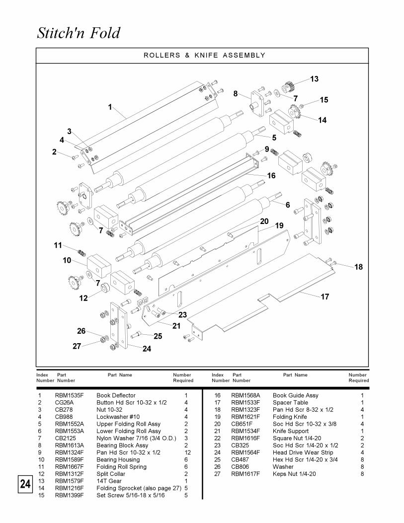
Stitch'n Fold ROLLERS & KNIFE ASSEMBLY
Index Part Part Name NumberNumber Number Required
Index Part Part Name NumberNumber Number Required
16 RBM1568A Book Guide Assy 117 RBM1533F Spacer Table 118 RBM1323F Pan Hd Scr 8-32 x 1/2 419 RBM1621F Folding Knife 120 CB651F Soc Hd Scr 10-32 x 3/8 421 RBM1534F Knife Support 122 RBM1616F Square Nut 1/4-20 223 CB325 Soc Hd Scr 1/4-20 x 1/2 224 RBM1564F Head Drive Wear Strip 425 CB487 Hex Hd Scr 1/4-20 x 3/4 826 CB806 Washer 827 RBM1617F Keps Nut 1/4-20 8
1 RBM1535F Book Deflector 12 CG26A Button Hd Scr 10-32 x 1/2 43 CB278 Nut 10-32 44 CB988 Lockwasher #10 45 RBM1552A Upper Folding Roll Assy 26 RBM1553A Lower Folding Roll Assy 27 CB2125 Nylon Washer 7/16 (3/4 O.D.) 38 RBM1613A Bearing Block Assy 29 RBM1324F Pan Hd Scr 10-32 x 1/2 1210 RBM1589F Bearing Housing 611 RBM1667F Folding Roll Spring 612 RBM1312F Split Collar 213 RBM1579F 14T Gear 114 RBM1216F Folding Sprocket (also page 27) 515 RBM1399F Set Screw 5/16-18 x 5/16 5
1
34
2
5
6
7
7
8
9
11
10
12
13
15
14
16
17
18
20 19
7
2321
25
24
26
27
25
ISP Stitching & Bindery ProductsA D i v i s i o n O f S a m u e l S t r a p p i n g S y s t e m s
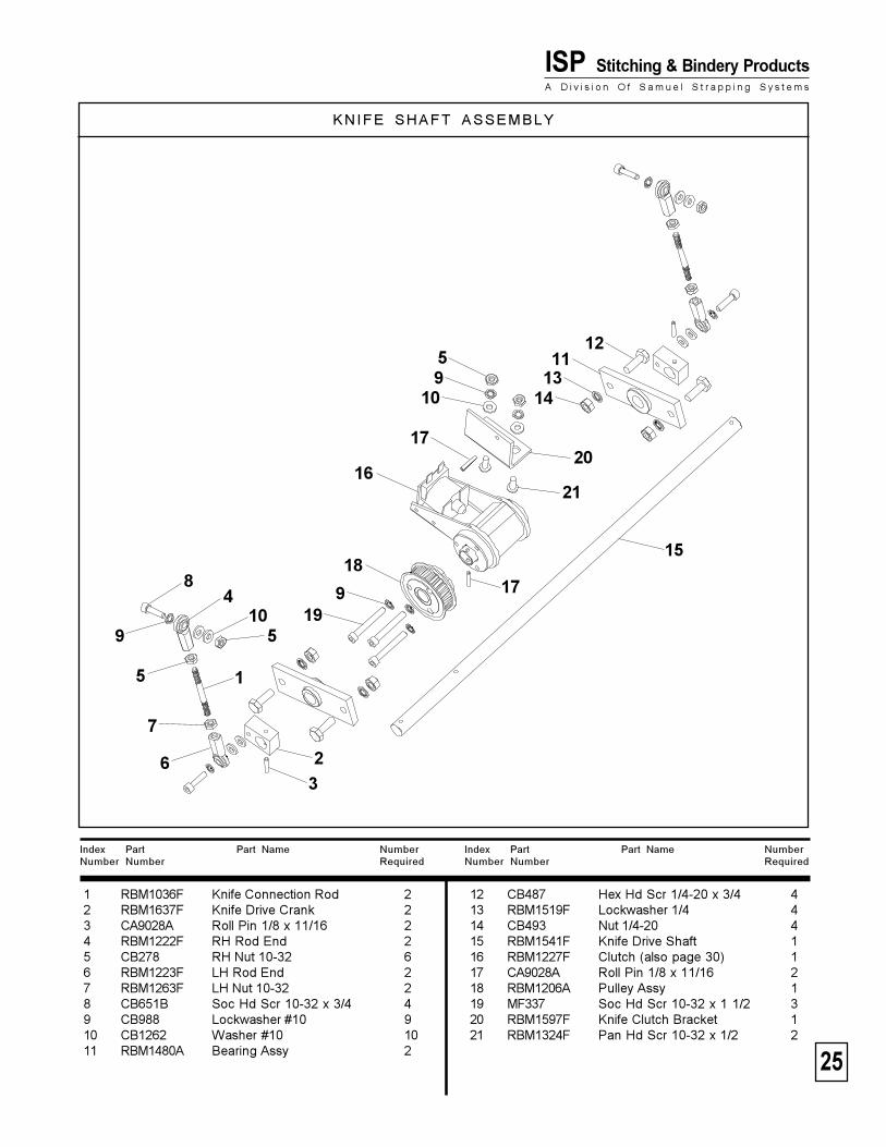
KNIFE SHAFT ASSEMBLY
Index Part Part Name NumberNumber Number Required
Index Part Part Name NumberNumber Number Required
12 CB487 Hex Hd Scr 1/4-20 x 3/4 413 RBM1519F Lockwasher 1/4 414 CB493 Nut 1/4-20 415 RBM1541F Knife Drive Shaft 116 RBM1227F Clutch (also page 30) 117 CA9028A Roll Pin 1/8 x 11/16 218 RBM1206A Pulley Assy 119 MF337 Soc Hd Scr 10-32 x 1 1/2 320 RBM1597F Knife Clutch Bracket 121 RBM1324F Pan Hd Scr 10-32 x 1/2 2
1 RBM1036F Knife Connection Rod 22 RBM1637F Knife Drive Crank 23 CA9028A Roll Pin 1/8 x 11/16 24 RBM1222F RH Rod End 25 CB278 RH Nut 10-32 66 RBM1223F LH Rod End 27 RBM1263F LH Nut 10-32 28 CB651B Soc Hd Scr 10-32 x 3/4 49 CB988 Lockwasher #10 910 CB1262 Washer #10 1011 RBM1480A Bearing Assy 2
1
23
510
4
9
5
8
6
7
919
1817
15
17
2116
1413
20
910
512
11
26
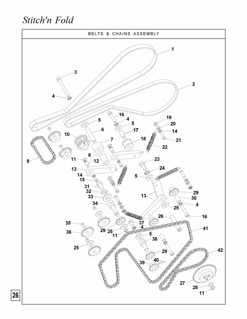
Stitch'n FoldBELTS & CHAINS ASSEMBLY
1
2
3
4
5
6
7
89
10
11 12
131415
11
11
45
16
1717
18
1920
14
2122
23
24
5
13
25
26
2728
2930
4
16
313233
34
29 25
35
36
25
374
538
29
39 40
41
42
27
ISP Stitching & Bindery ProductsA D i v i s i o n O f S a m u e l S t r a p p i n g S y s t e m s
Index Part Part Name NumberNumber Number Required
1 RBM1211F Timing Belt 3/8" Wide 12 RBM1210F Timing Belt 1/2" Wide 13 D44958F Soc Hd Scr 1/4-20 x 2 1/2 14 RBM1519F Lockwasher 1/4 55 CB718 Washer 46 RBM1294F Knife Idler Shaft 17 RBM1291F Idler Roll 18 RBM1295F Idler Spacer 19 RBM1673F Chain - 44L 110 RBM1207F Reducer Pulley 10 Teeth 111 CB837B Retaining Ring 3/8 412 RBM1045F Idler Bracket Stud 213 RBM1044A Idler Bracket Assy 414 CB988 Lockwasher #10 615 CG26 Button Hd Scr 10-32 x 3/8 216 CB629B Soc Hd Scr 1/4-20 x 1 1/4 317 RBM1293F Stitcher Idler Shaft 118 RBM1360F Idler Roll 119 CB860B Elastic Stop Nut 10-32 420 CB278 Nut 10-32 421 CG26C Button Hd Scr 10-32 x 3/4 422 RBM1231F Idler Spring 423 CB606 Hex Hd Scr 5/16-18 x 3/4 124 CB895 Lockwasher 5/16 125 CB2125 Nylon Washer 7/16 (3/4 O.D.) 426 RBM1288F Sprocket Stud 127 RBM1286A Dual Sprocket Assy 128 CT32 Washer 129 RBM1218A Idler Sprocket Assy 430 RBM1289F Idler Stud 231 CB328 Hex Hd Scr 3/8-16 x 5/8 132 CB889 Washer 3/8 133 CB179 Lockwasher 134 RBM1662F Idler Shaft 135 RBM1399F Set Screw 5/16-18 x 5/16 536 RBM1216F Folding Sprocket 537 CK31 Hex Hd Scr 1/4-20 x 1/2 138 RBM1633F Idler Shaft (mount on bearing) 139 RBM1217F Drive Sprocket 140 CA9028A Roll Pin 1/8 x 11/16 141 RBM1674F Chain - 156L 142 RBM1670F Chain - 62L 1
28
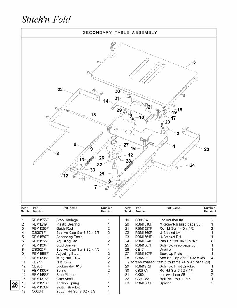
Stitch'n Fold SECONDARY TABLE ASSEMBLY
Index Part Part Name NumberNumber Number Required
Index Part Part Name NumberNumber Number Required
19 CB988A Lockwasher #8 220 RBM1310F Microswitch (also page 30) 121 RBM1327F Rd Hd Scr 4-40 x 1/2 222 RBM1560F U-Bracket LH 123 RBM1561F U-Bracket RH 124 RBM1324F Pan Hd Scr 10-32 x 1/2 825 RBM1567F Solenoid (also page 30) 126 CE17 Washer 127 RBM1507F Back Up Plate 128 CB651F Soc Hd Cap Scr 10-32 x 3/8 4 (2 screws connect item 6 to items 44 & 45 page 20)29 RBM1272F Solenoid Pivot Bracket 130 CB287A Rd Hd Scr 6-32 x 1/4 231 CK50 Lockwasheer #6 232 CA9028A Roll Pin 1/8 x 11/16 133 RBM1685F Spacer 2
1 RBM1555F Stop Carriage 12 RBM1249F Plastic Bearing 43 RBM1588F Guide Rod 24 D30676F Soc Hd Cap Scr 8-32 x 3/8 25 RBM1587F Secondary Table 16 RBM1556F Adjusting Bar 27 RBM1664F Stud Bracket 18 D30523F Soc Hd Cap Scr 8-32 x 1/2 49 RBM1665F Adjusting Stud 210 RBM1308F Wing Nut 10-32 211 CB278 Nut 10-32 212 CB988 Lockwasher #10 413 RBM1305F Spring 214 RBM1483F Stop Platform 115 RBM1313F Gate Shaft 116 RBM1518F Torsion Spring 117 RBM1506F Switch Bracket 118 CG26N Button Hd Scr 8-32 x 3/8 4
1
2
3
5
6
78
169
13
33
27
26
25
32
1211
12
10
14
15
4
211819
1720
22
23
2428
29
30
31
29
ISP Stitching & Bindery ProductsA D i v i s i o n O f S a m u e l S t r a p p i n g S y s t e m s
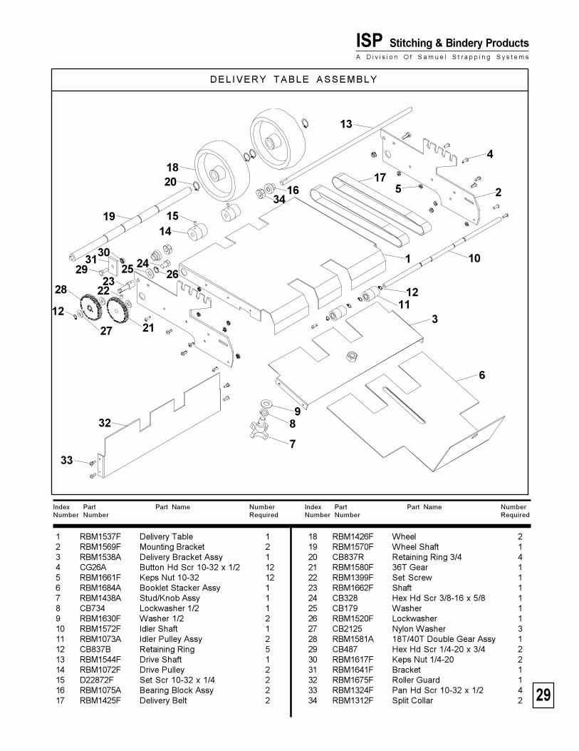
DEL IVERY TABLE ASSEMBLY
Index Part Part Name NumberNumber Number Required
Index Part Part Name NumberNumber Number Required
18 RBM1426F Wheel 219 RBM1570F Wheel Shaft 120 CB837R Retaining Ring 3/4 421 RBM1580F 36T Gear 122 RBM1399F Set Screw 123 RBM1662F Shaft 124 CB328 Hex Hd Scr 3/8-16 x 5/8 125 CB179 Washer 126 RBM1520F Lockwasher 127 CB2125 Nylon Washer 328 RBM1581A 18T/40T Double Gear Assy 129 CB487 Hex Hd Scr 1/4-20 x 3/4 230 RBM1617F Keps Nut 1/4-20 231 RBM1641F Bracket 132 RBM1675F Roller Guard 133 RBM1324F Pan Hd Scr 10-32 x 1/2 434 RBM1312F Split Collar 2
1 RBM1537F Delivery Table 12 RBM1569F Mounting Bracket 23 RBM1538A Delivery Bracket Assy 14 CG26A Button Hd Scr 10-32 x 1/2 125 RBM1661F Keps Nut 10-32 126 RBM1684A Booklet Stacker Assy 17 RBM1438A Stud/Knob Assy 18 CB734 Lockwasher 1/2 19 RBM1630F Washer 1/2 210 RBM1572F Idler Shaft 111 RBM1073A Idler Pulley Assy 212 CB837B Retaining Ring 513 RBM1544F Drive Shaft 114 RBM1072F Drive Pulley 215 D22872F Set Scr 10-32 x 1/4 216 RBM1075A Bearing Block Assy 217 RBM1425F Delivery Belt 2
1
2
3
4
5
6
98
7
10
1112
12
13
1415
3416
1718
19
20
21
28 22
27
2325 24
262931
30
32
33
30
Stitch'n FoldMAIN CONTROL PANEL
Index Part Part Name NumberNumber Number Required
Index Part Part Name NumberNumber Number Required
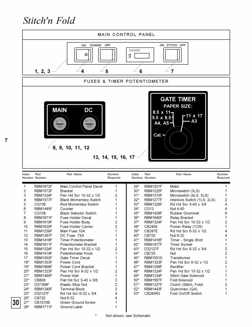
29* RBM1201F Motor 130* RBM1225F Microswitch (3LS) 131* RBM1310F Microswitch (4LS, 5LS) 132* RBM1277F Interlock Switch (1LS, 2LS) 233* RBM1328F Rd Hd Scr 4-40 x 3/4 434* CG13 Nut 4-40 435* RBM1428F Rubber Grommet 636* RBM1640F Relay Bracket 137* RBM1324F Pan Hd Scr 10-32 x 1/2 238* CB2454 Power Relay (1CR) 139* CB287E Rd Hd Scr 6-32 x 1/2 440* CB720 Nut 6-32 441* RBM1416F Timer - Single Shot 142* RBM1417F Timer Socket 143* D32127F Rd Hd Scr 6-32 x 3/4 244* CB720 Nut 245* RBM1501A Transformer 146* RBM1323F Pan Hd Scr 8-32 x 1/2 247* RBM1298F Rectifier 148* RBM1324F Pan Hd Scr 10-32 x 1/2 149* RBM1234F Stitch Gate Solenoid 150* RBM1567F Fold Solenoid 151* RBM1227F Clutch (Stitch, Fold) 252* RBM1443F Quencharc (QA) 153* CB285R2 Fold On/Off Switch 1
1 RBM1672F Main Control Panel Decal 12 RBM1573F Bracket 13 RBM1324F Pan Hd Scr 10-32 x 1/2 24 RBM1577F Black Momentary Switch 15 CG136 Red Momentary Switch 16 RBM1445F Counter 17 CG138 Black Selector Switch 18 RBM1671F Fuse Holder Decal 19 RBM1619F Fuse Holder Body 210 RBM1620F Fuse Holder Carrier 211 RBM1239F Main Fuse 10A 112 RBM1267F DC Fuse .75A 113 RBM1418F Timer Potentiometer 114 RBM1611F Potentiometer Bracket 115 RBM1324F Pan Hd Scr 10-32 x 1/2 216 RBM1419F Potentiometer Knob 117 RBM1452F Gate Timer Decal 118* RBM1353F Power Cord 119* RBM1668F Power Cord Bracket 120* RBM1323F Pan Hd Scr 8-32 x 1/2 221* RBM1495F Power Inlet 122* CB808 Flat Hd Scr 5-40 x 3/8 223* D27398F Elastic Stop Nut 224* RBM1240F Terminal Block 225* D32127F Rd Hd Scr 6-32 x 3/4 426* CB720 Nut 6-32 427* CB1070B Green Ground Screw 128* RBM1711F Ground Label 1
FUSES & T IMER POTENTIOMETER
1, 2, 3 75 6
* Not shown; see Schematic.
ON OFF
COUNTS
ON STITCH OFFPOWER
7
MAIN DC
4
8, 9, 10, 11, 12
13, 14, 15, 16, 17
GATE TIMER
11 x 17A3
8.5 x 115.5 x 8.5A4, A5
Cal.
PAPER SIZE:
31
ISP Stitching & Bindery ProductsA D i v i s i o n O f S a m u e l S t r a p p i n g S y s t e m s
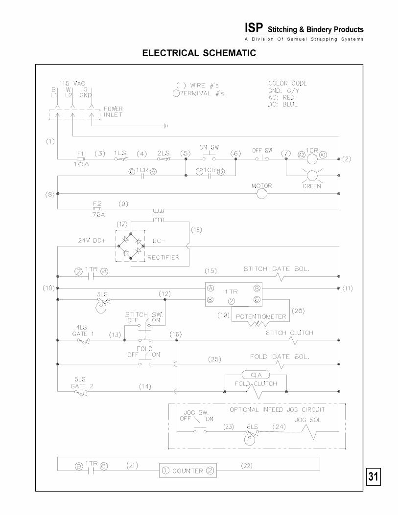
ELECTRICAL SCHEMATIC
32
Stitch'n Fold
Index Part Part Name NumberNumber Number Required
Index Part Part Name NumberNumber Number Required
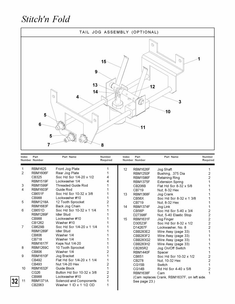
1 RBM1625 Front Jog Plate 12 RBM1606F Rear Jog Plate 1
CB325 Soc Hd Scr 1/4-20 x 1/2 4RBM1519F Lockwasher 1/4 4
3 RBM1599F Threaded Guide Rod 14 RBM1603F Guide Rod 1
CB651F Soc Hd Scr 10-32 x 3/8 1CB988 Lockwasher #10 1
5 RBM1218A 12 Tooth Sprocket 2RBM1683F Back Jog Chain 1
6 CB651D Soc Hd Scr 10-32 x 1 1/4 1RBM1289F Idler Stud 1CB988 Lockwasher #10 1CB1262 Washer #10 1
7 CB629B Soc Hd Scr 1/4-20 x 1 1/4 1RBM1289F Idler Stud 1CB806 Washer 1/4 1CB718 Washer 1/4 1RBM1617F Keps Nut 1/4-20 1
8 RBM1269C 10 Tooth Sprocket 1CB806 Washer 1/4 2
9 RBM1610F Jog Bracket 1CB492 Flat Hd Scr 1/4-20 x 1 1/4 1CB493 Nut 1/4-20 Hex 2
10 RBM1632F Guide Block 1CG26 Button Hd Scr 10-32 x 3/8 2CB988 Lockwasher #10 2
11 RBM1371A Solenoid and Components 1CB2063 Washer 1 ID x 1 1/2 OD 1
12 RBM1626F Jog Shaft 1RBM1250F Bushing, .375 Dia 2RBM1586F Retaining Ring 2RBM1375F Extension Spring 1CB206B Flat Hd Scr 8-32 x 5/8 1CB719 Nut, 8-32 Hex 1
13 RBM1368F Jog Crank 1CB56X Soc Hd Scr 8-32 x 1 3/8 1CB719 Nut, 8-32 Hex 1
14 RBM1374F Jog Link 1CB56P Soc Hd Scr 5-40 x 3/4 2D27398F Nut, 5-40 Elastic Stop 2
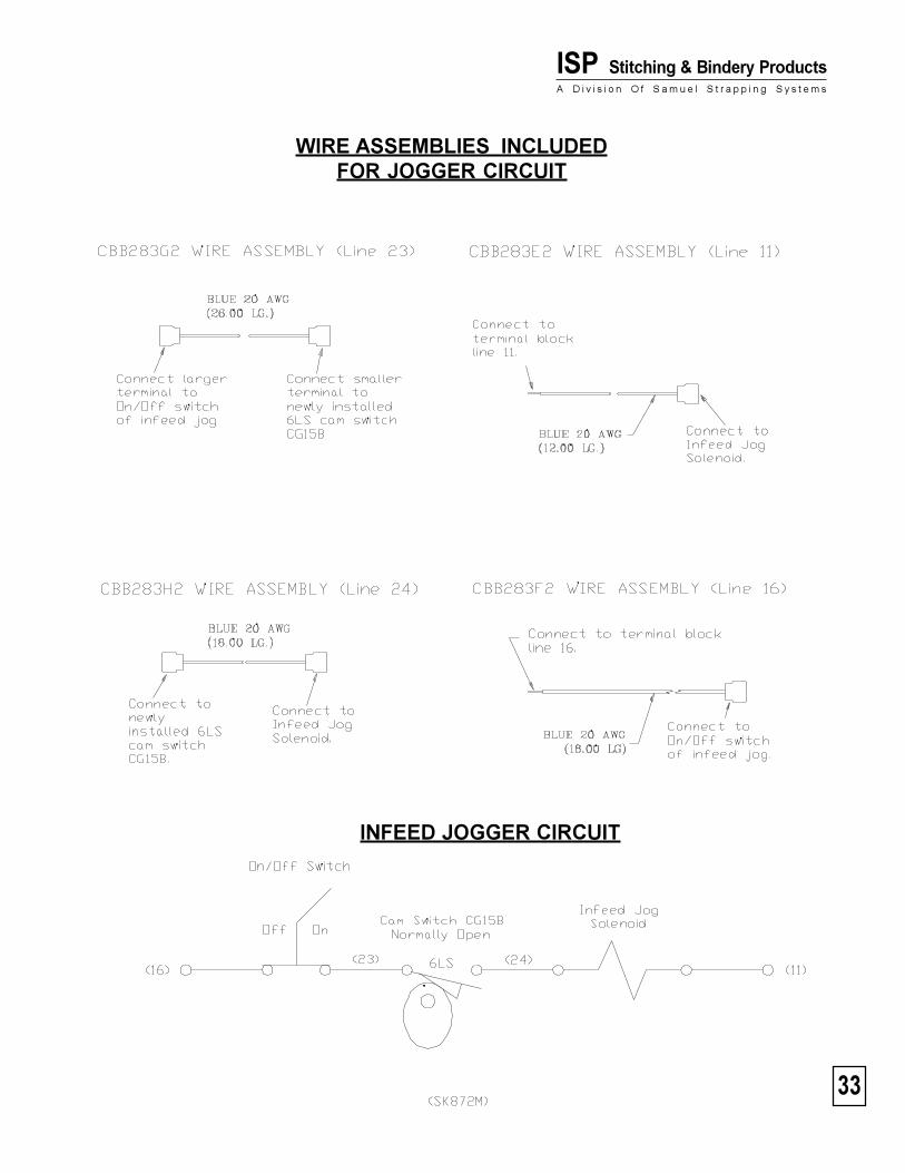
15 RBM1631F Jog Finger 2D30523F Soc Hd Scr 8-32 x 1/2 2D14267F Lockwasher, No. 8 2CBB283E2 Wire Assy (page 33) 1CBB283F2 Wire Assy (page 33) 1CBB283G2 Wire Assy (page 33) 1CBB283H2 Wire Assy (page 33) 1CB285R2 Jog On/Off Switch 1RBM1440F Spacer 1CB651 Soc Hd Scr 10-32 x 1/2 2CB278 Nut, 10-32 Hex 2CG15B Switch 1CG14B Rd Hd Scr 4-40 x 5/8 2RBM1638F Cam 1(Cam replaces Crank, RBM1637F, on left side.See page 23.)
TA IL JOG ASSEMBLY (OPTIONAL)
1
43
7 8
5
6
5
9
10
11
121314
15
33
ISP Stitching & Bindery ProductsA D i v i s i o n O f S a m u e l S t r a p p i n g S y s t e m s
WIRE ASSEMBLIES INCLUDEDFOR JOGGER CIRCUIT
INFEED JOGGER CIRCUIT
34
Stitch'n Fold
Index Part Part Name NumberNumber Number Required
Index Part Part Name NumberNumber Number Required
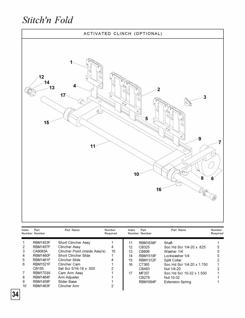
1 RBM1453F Short Clincher Assy 12 RBM1457F Clincher Assy 43 CA9083A Clincher Point (inside Assy's) 104 RBM1460F Short Clincher Slide 15 RBM1461F Clincher Slide 46 RBM1521F Clincher Cam 1
CB155 Set Scr 5/16-18 x .500 27 RBM1703A Cam Arm Assy 18 RBM1464F Arm Adjuster 19 RBM1458F Slider Base 110 RBM1463F Clincher Arm 2
ACTIVATED CL INCH (OPTIONAL)
11 RBM1639F Shaft 112 CB325 Soc Hd Scr 1/4-20 x .625 513 CB806 Washer 1/4 514 RBM1519F Lockwasher 1/4 515 RBM1312F Split Collar 216 CT365 Soc Hd Scr 1/4-20 x 1.750 1
CB493 Nut 1/4-20 217 MF337 Soc Hd Scr 10-32 x 1.500 1
CB278 Nut 10-32 1RBM1694F Extension Spring 1
1
2
3
4
5
6
7
8
9
10
12
11
1413
17
16
15

35
ISP Stitching & Bindery ProductsA D i v i s i o n O f S a m u e l S t r a p p i n g S y s t e m s

36
Stitch'n Fold
USA:718 Marquette Street Racine, WI 534031-800-345-6641 1-414-632-5115Fax: 1-414-632-9240www.ispstitching.com
FORM QF96 1/99
OUTSIDE USA:6843 Santa Fe Drive Hodgkins, IL 605251-708-482-9500Fax: 1-708-482-0274
ISP Stitching & Bindery ProductsA D i v i s i o n O f S a m u e l S t r a p p i n g S y s t e m s
ISP Stitching & Bindery ProductsA D i v i s i o n O f S a m u e l S t r a p p i n g S y s t e m s


![O No Stitching [Single laver suit only] Stitching Styles Stitching ...hotshoeracewear.com/wp-content/uploads/2018/12/Suit-Order-form-… · [Single laver suit only] Stitching Styles](https://img.dokumen.tips/doc/110x75/5ed667d875f83015187a9121/o-no-stitching-single-laver-suit-only-stitching-styles-stitching-single-laver.jpg)


![SKF solutions for printing, bindery, finishing, converting ... · PDF fileSKF solutions for printing, bindery, finishing, converting and packaging machinery ; _ j ] : ; bergab@ya.ru](https://img.dokumen.tips/doc/110x75/5aa87d137f8b9a95188b9bfb/skf-solutions-for-printing-bindery-finishing-converting-solutions-for-printing.jpg)