Embed Size (px)
Citation preview

^O-Ao^S t h I RIA-76-U420
Cy No. 2
i ISADACS Technical Ubrtry
5 0712 01005775 9
AD
R-CR-75-0^8
ISOTHERMAL FORGING OF Ti-6AI-4V ALLOY
AS AN IMPROVED PROCESS
FOR FABRICATING WEAPON COMPONENTS
FINAL REPORT TECHNICAL LIBRARY
W. D. Spiegelberg TRW, Inc.
and
F. E. Anderson Rock Island Arsenal
JANUARY 1976
PREPARED BY TRW, INC. and
ROCK ISLAND ARSENAL
DISTRIBUTION STATEMENT
Approved for public release, distribution unlimited.
RESEARCH DIRECTORATE
GENERAL THOMAS J. RODMAN LABORATORY
ROCK ISLAND ARSENAL
ROCK ISLAND, ILLINOIS 61201
•
1
1
\
DISPOSITION INSTRUCTIONS:
Destroy this report when it is no longer needed. Do not return it to the originator.
•
DISCLAIMER:
The findings of this report are not to be construed as an official Department of the Army position unless so designated by other authorized documents.
The citation of commercial products in this report does not constitute an official indorsement or approval of such products.
•
s •
•
"*•
Do not return it •
•
•
I
"•
f *

UNCLASSIFIED SECURITY CLASSIFICATION OF THIS PAGE (When Date Entered)
REPORT DOCUMENTATION PAGE READ INSTRUCTIONS BEFORE COMPLETING FORM
1. REPORT NUMBER
R-CR-75-0^8 2. 30VT ACCESSION NO 3. RECIPIENT'S CATALOG NUMBER
4. TITLE (and Subtitle)
ISOTHERMAL FORGING OF Ti-6Al-i»v ALLOY AS AN IMPROVED PROCESS FOR FABRICATING WEAPON COMPONENTS
S. TYPE OF REPORT & PERIOD COVERED
Final Report
6. PERFORMING ORG. REPORT NUMBER
ER-7665-5 7. AUTHORC*;
W. D. Spiegelberg, TRW, Inc. F. E. Anderson, Rock Island Arsenal
a. CONTRACT OR GRANT NUMBERfiJ
DAAF03-73-C-0093 AMS Code 3297.06.7256.02
9. PERFORMING ORGANIZATION NAME AND ADDRESS
TRW, Inc. 23555 Euclid Avenue Cleveland, Ohio kk\\l
10. PROGRAM ELEMENT. PROJECT, TASK AREA a WORK UNIT NUMBERS
AMS Code 3297.06.7256.02
1 I. CONTROLLING OFFICE NAME AND ADDRESS
CDR, Rock Island Arsenal GEN Thomas J. Rodman Laboratory Rock Island, 111inois 61201
12. REPORT DATE
January I97A 11. NUMBER OF P>
lll» 14. MONITORING AGENCY NAME a ADDRESSfJf dlllarmnl /rom Controlling Otllce) 15. SECURITY CLASS. fo< thlm report)
Unclassi fied
Mm. DECLASSIFI CATION/DOWN GRADING SCHEDULE
16. DISTRIBUTION ST ATEMEN T (al thle Report)
Approved for public release; distribution unlimited.
17. DISTRIBUTION STATEMENT (ol (ho eb,tract entered In Block 10, It different from Report)
18. SUPPLEMENTARY NOTES
19. KEY WORDS (Continue on reverie aide it necessary and Identity by block number)
1. Isothermal Forging /». Lubrication
2. Fabrication
3 Weapon Components
5. Preform Design
6. Titanium Alloy (Ti-6Al-AV)
20. ABSTRACT (Continue on rmvorae tide II naceaamry and Identity by block number)
A program to evaluate the isothermal forging of titanium alloys, e.g., Ti-6A1-*»V, as an improved manufacturing process for the production of light weight, high strength weapon components has been conducted. The program was performed in two phases.
The first phase consisted of the isothermal forging of a simulated weapon com- ponent having thin high ribs, a large volume projection, and a uniformly thin web. This effort established optimum starting material properties, preform
DD .rt FORM AN 73 1473 EDITION OF I NOV SS IS OBSOLETE UNCLASSIFIED I
SECURITY CLASSIFICATION OF THIS PAGE (Whan Dmtm Entered)

UNCLASSIFIED SECURITY CLASSIFICATION OF THIS PAGEfHTien Date Entered)
20 (continued)
design, lubrication practice, tooling design and forging conditions. The important aspects of lubrication and preform design were explored in detail. The results of the first phase work were incorporated into a process specifi- cation which was used as a basis for the second phase effort.
The second phase consisted of the manufacture of a demonstration weapon com- ponent, the M85 Machine Gun Cover, by isothermal forging. The process specifi- cation prepared in Phase I was followed throughout, and preforms were designed according to the rules governing volume distribution, initial contact points and fill timing developed for the simulated part. The forgings produced were used to assess the capabilities and economics of the isothermal forging process,
Economic analysis of the process reveals that it is potentially cost effective compared to current manufacturing techniques with a cost savings approaching 15% despite the higher cost of the titanium alloy. The key to this cost effec- tiveness lies in the achievement of an optimum balance between the number of details that are isothermally forged to net dimensions and those that are finished by machining. Machining costs fall with the number of net forged details but forging costs rise with complexity of the preform. (Spiegelberg, W. D. and Anderson, F. E.)
i i UNCLASSIFIED SECURITY CLASSIFICATION OF THIS PAGEfWben Dalm Entered)

FOREWORD
This final report was prepared by Dr. W. D. Spiegelberg of TRW, Inc., Cleveland, OH in compliance with Contract DAAF03-73-C-0093 and by Mr. F. E. Anderson of the Research Directorate, GEN Thomas J. Rodman Laboratory, Rock Island Arsenal, Rock Island, IL 61201.
The work was authorized as part of the Manufacturing Methods and Technology Program of the U.S. Army Materiel Development and Readiness Command and was administered by the U.S. Army Production Equipment Agency.
iii

TABULAR DATA .
Table Page
I Certified Chemical Analyses and Mechanical Properties of Ti-6A1-4V Stock for Phase I Isothermal Forging Trials 14
II Experimental Forging Conditions for First Iteration Simulated Component Isothermal Forgings 28
III Experimental Conditions for Second Iteration Phase I Simulated Weapon Component Isothermal Forgings 37
IV Results of Dimensional Inspection of Phase I Isothermal Forgings 45-46
V Effect of Isothermal Forging on Interstitial Element Concentration 57
VI Effect of Isothermal Forging on Room and Elevated Temper- ature Tensile Properties of Ti-6A1-4V 59
VII Instrumented Charpy V-Notch Impact Tests on Miniature Ti-6Al-l»V Samples 62
VI I I Isothermal Forging Conditions,for M$5 Covers, First Sequence 76
IX Certified Chemical Analysis and Mechanical Properties of Ti-6A1-*»V Forging Stock 86
X Process Economics - M85 Cover Conventional Process 94-96
vi
ILLUSTRATIONS
Flgure Page
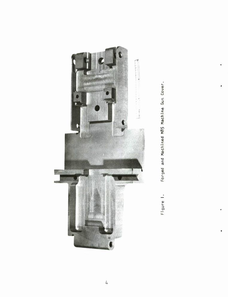
1 Forged and Machined M85 Machine Gun Cover *•
2 Cover for M85 Machine Gun 6
3 Simulated Complex Weapon Component for Isothermal Forging Studies 8
k Tooling Assembly for Isothermal Forging of M85 Covers 10
5 IN-100 Alloy Ring Die (Center), Upper Punch (Right), and Ejector (Left) Designed for Isothermal Forging Studies with Simulated Weapon Component 11
6 Die System for Isothermal Forging of Ti-6A1-4V Simulated Weapon Component Shown Installed in 150-Ton Hydraulic Press . 13
7 Photomicrographs Depicting the Microstructure of the 1-inch Thick Ti-6A1-4V Alloy Isothermal Forging Stock in the As- Received Condition 15-16
8 Photomicrographs Depicting the Microstructure of the 5/8-inch Thick Ti-6A1-4V Alloy Isothermal Forging Stock in the As- Received Condition 17
9 Photomicrographs Depicting the Microstructure of the 1/4-inch Thick Ti-6A1-4V Alloy Isothermal Forging Stock in the As- Received Condition 18
10 Flat Plate Preforms for Isothermal Forging of Phase I Simulated Weapon Component, Preform EP 200 at Left, EP 500 at Right 21
11 Top and Bottom Views of "Double-Radiused" Preforms for Isothermal Forging of Phase I Simulated Weapon Component ... 22
12 Top and Bottom Views of '.'S ingle-Radi used" Preforms for Isothermal Forging of Phase I Simulated Weapon Component ... 23
13 Top and End Views of "Edge Notched" Preforms for Isothermal Forging of Phase I Simulated Weapon Component 2k
14 Phase I Simulated Weapon Component No. EP 200-5 in the As-Forged Condition 30
15 Phase I Simulated Weapon Component No. DR-1000-8 in the As-Forged Condition 31
vi i

ILLUSTRATIONS (CONTINUED)
Figure Page
16 Two Views of Isothermally Forged and Sandblasted Simulated Weapon Components 32
17 Two Views of Isothermally Forged and Sandblasted Simulated Weapon Components 33
18 Two Views of Isothermally Forged and Sandblasted Simulated Weapon Components 3^
19 Web Thickness as a Function of Dwell Time During Isothermal Forging of Simulated Components 36
20 Second Iteration Phase I Simulated Weapon Component Isothermal Forgings, As-Forged and Lightly Sandblasted 38
21 Simulated Weapon Component Forgings Illustrating Effect of Various Forging Lubricants ^0
22 Simulated Weapon Component Forgings Illustrating Effect of Preform Design hi
23 Preform Design Utilized in Isothermal Forging of Simulated Weapon Components ^3
2k Macrostructure of Isothermally Forged Simulated Components Illustrating Grain Structure U6
25 Cross Section Through Isothermal Forging Illustrating Micro- structures at Various Locations at 100X Magnification ... 51
26 Cross Section Through Isothermal Forging Illustrating Micro- structures at 250X Magnification and Rockwell C. Hardness at Various Locations 52
27 Cross Section Through Isothermal Forging Illustrating Micro- structures at 100X Magnification 53
28 Cross Section Through Isothermal Forging Illustrating Micro- structures at 250X Magnification and Rockwell C. Hardness Values at Various Locations 5^
29 Typical Oscilloscope Traces Illustrating Strain Gage and Velocity Monitoring Signals for Instrumented Charpy V-Notch Impact Tests 55
30 Results of Instrumented Charpy V-Notch Impact Testing on Subscale Impact Specimens, Impact Energy vs Test Temperature 63
vi i i

ILLUSTRATIONS (CONTINUED)
Figure Page
31 Schematic of Isothermal Forging Die for Cover 67
32 Diagram Illustrating Cross-Sectional Area Requirements as a Function of Position Along Longitudinal Centerline of M85 Cover 68
33 Longitudinal Section Through Lower Punch with Two Preforms Superimposed 70
3k Schematic Illustration of Pressure Requirements in Isothermal Forging of Simulated Weapon Component 71-72
35 Three Ti-6Al-i4V Isothermal Forging Preforms for the M85 Cover . jk
36 Microstructure of Ti-6A1-4V Forging Plate Stock from Timet Heat Number G-1386 75
37 First Iteration M85 Cover Isothermal Forgings . 78
38 Upper Punch Component of Isothermal Forging Tooling Illu- strating Lateral Dimensions as Surface Ground 81
39 Upper Punch Component of Isothermal Forging Tooling Illu- strating Working Face Dimensions as Machined by EDM 82
^•0 Preform Blank As-Received from Titanium Supplier Showing Outline of Finished Preform Shape 83
41 Preform Design for Isothermally Forged M85 Cover 8*4
Ul Microstructure of Ti-6Al-l»V Forging Plate Stock from RMI Heat Number 30*4209 87
43 Details of Forging 9 in Second Sequence Isothermal Forging . . 90
kh M85 Covers as Forged Showing Details of Bottom Surface .... 92
!X

I. INTRODUCTION
The fabrication of weapon components from titanium alloys in place of steel is attractive since this substitution would reduce the weight of weapon components significantly with no loss in mechanical properties. Unfortunately, titanium alloys are much more expensive than the steels they would replace, and are difficult to fabricate by conventional proc- esses. However, because of the high strain rate sensitivity of titanium alloys, a potentially attractive manufacturing approach for fabricating weapon components from titanium alloys is the hot die, isothermal, low deformation rate (creep) forging process. Development of a workable isothermal forging process for titanium alloys has been in progress under a continuing series of DOD sponsored programs since 1957^' but only since 1970 has notable success been achieved. This success has included experi- mental manufacture of small titanium alloy structural forgings and of titanium alloy F-lll aircraft nose wheels.'^) The most recent extensions of isothermal forging technology have been toward production of larger and more complex aircraft structural components. \3i%5) Several current problem areas still exist in isothermal forging processes. However, solution to these have been proposed and it appears timely for application of the process to advanced weapons components through a carefully engi- neered development approach.
Among the areas that must be considered in development of an iso- thermal forging process are:
Hot Die Materials and Design
Hot dies must be capable of retaining precision form during long-time service while resisting the adverse effects of steep thermal gradients (present at least during heatup) , mechanical stresses which on the average are low but may reach significant magnitudes at points of stress concentration, and impurities in forging lubricants that can give
(1) H.R. Nichols, W.H. Graft, V. Pulsifer, and P.R. Gouwens, "Develop- ment of High Temperature Die Materials," AMC TR-59~7-579, Armour Research Foundation, October 1959.
(2) T. Watmough, K.M. Kulkarni, N.M. Parikh, "Isothermal Forging of Titanium Alloys Using Large, Precision Cast Dies," AFML-TR-70-161, NT Research Institute, July 1970.
(3) K.M. Kulkarni, T. Watmough, D. Stawarz, N. Parikh, "Isothermal Forg- ing of Titanium Alloy Bulkheads," AFML-7^-138, I IT Research Institute, August 197^.
CO A.J. Vazquez and A.F. Hayes, "Isothermal Forging of Reliable Structural Forgings," AFML-TR-71*-123, Ladish Company, June 197^.
(5) C.C. Chen, W.H. Couts, C.P. Gure, S.C. Jain, "Advanced Isothermal Forging, Lubrication, and Tooling Process," I R-128-M1) , Wyman- Gordon Company, July 197^.
1

rise to die surface deterioration over long periods of operation. A material for hot die application must possess excellent resistance to creep deformation while retaining sufficient ductility to avoid cracking, relatively high ther- mal diffusivity to minimize temperature gradients, superior resistance to elevated temperature oxidation and sulfidation, and a high elastic modular and low thermal expansion coefficient.
Die Heating System
The die heating technique must afford uniform, accurate die tem- peratures for reproducible control of thermal expansion-contract ion effects on dies and forgings. Design parameters must provide for minimization of thermal gradients applied during heating and steady forging, use of insula- tion techniques to prevent excessive heat loss and power consumption, and elimination of thermal distortion within the die cavity.
Forging Lubricants and Lubricant Application Techniques
The current isothermal forging problem of lubricant accumulation impeding metal flow and impairing surface finish requires utilization of lubricants providing low friction and high film strength without excessive lubricant thickness requirements. The lubricant must also protect titanium alloys from alpha case formation and must be free of undesirable impurities that can cause localized attack of hot dies.
Conventional isothermal forging practice is to apply a commercial glass precoat (such as Markal CRT-22) to the workpiece preform prior to pre- heating for forging. The glass fuses and is viscous at the isothermal forg- ing temperature. Occasional breakthrough of the film and galling of the titanium to the die has been reported. Also, if sufficient precoat is applied to the preform to avoid this, the thicker layer of viscous glass is reported to preferentially fill and clog the cavity recesses and to be the cause of incompletely formed forgings in these areas. Periodically, the dies must be cooled, and the residual glass in the die cavity recesses must be painstakingly chipped out and removed.
Early TRW efforts in conventional forging with high temperature dies revealed the severity of the problem of viscous glasses sticking to the die surfaces as well as the workpiece surfaces and fouling the working sur- faces of the dies with stringers of glass. More recent efforts have empha- sized development of effective precoat-type lubricants which provide improved film strength and which do not themselves adhere to the dies during forging. These experimental lubricants are of the hydrodynamic "squeeze film" type, but are filled with boundary film lubricant powders to afford release without sticking, and lower interfacial friction. Very significant metal flow occurs with their use during isothermal creep forging of thin sections of an even more creep resistant titanium alloy (Ti 6A1-2Sn-^Zr-2Mo) at temperatures of 1600 and 1700°F and a die force of only 7500 psi.
Preform Design
Design of an optimized starting shape for the hot die forging process is one of the key factors in successful isothermal forging since the

preform governs precision through its influence on die fill, the occurrence of laps and seams and "flow-through" types of defects, grain size control through amount and uniformity of plastic deformation, and surface finish through its influence on lubricant distribution. The preform has an impor- tant effect on the economics of the process also; preform production costs must be minimized for hot die forging to be competitive.
Considerable experience has been acquired by TRW in employing the process for manufacture of small titanium alloy blades for turbine engines, and notable success has been achieved in the problem areas of die design and 1ubrication.(P>7) The current program was conducted under Contract DAAF03-73-C-0093 to apply the process for economical production of advanced titanium alloy weapons components.
The overall objective of this program was to demonstrate the advan- tage of isothermal forging of titanium alloys as an improved fabrication process for lightweight, high-strength weapons components. Specifically, two major goals were involved. The first was significant cost reduction by taking advantage of the precision forging capabilities inherent in the process which, for many shapes, allow use of the majority of forged dimen- sions and surfaces in the ''net" forged and heat treated condition; i.e., without subsequent machining. The second goal involved the desire for significant weight reduction without sacrificing useful strength; i.e., weight reduction without increasing section thickness (and weapon size)as would occur through use of lightweight materials weaker than the steels they replace.
To accomplish these goals, a two-phase effort was conducted. Phase I had the objectives of: 1) developing those new techniques that will make the isothermal forging process practical in terms of economy and reliability for the M85 cover; 2) determining the material properties that result from isothermal forging; and 3) developing a preliminary process specification for utilization in Phase II prototype production. Phase II consisted of confirmation of the final process specification through forging trials, pro- totype production and delivery of cover forgings, and preparation of an economic analysis of the process.
A photograph of a finished cover for the model M85 machine gun is provided in Figure 1. This component is conventionally produced from wrought AISI 4130 steel by a process that Includes hammer forging a blank to a rough form suitable for subsequent machining to the specifications of
(6) F.N. Lake, "Isothermal Hot Die Creep Forging of Small Titanium Alloy Compressor Blades," TRW Inc. Technical Memorandum No. 4647 December 1971.
(7) F.N. Lake, "Lubricant Development for Hot Die Forging of Small Blades,1
TRW Inc. Technical Memorandum No. 4712, December 1972.
ID > o
<_> c
<J
)) C
o ID 2:
LA OO
<D c
o 5 T3 C <0
XI 0) en u o
i- =1

/ g\ the finished part drawing, U.S. Army Part Number 7793151. Two views of the part selected from this drawing are provided in Figure 2.
The cover is mounted on the gun with the right hand side of View A-A forward. The transverse hole at the right of View A-A contains the hinge pin that allows raising and lowering the cover. For this reason this end of the cover is referred to as the "hinge pin end". The cover details In View A-A face downward when mounted on the gun and therefore this is a bottom view. The top side of the cover (not illustrated) is basically wihtout detail beyond that illustrated by the upper surface of Section E-E. During operation, shells are fed transversely across the widest section of the cover. The wide projections are referred to as the "wings" of the piece. The high wall at the forward end of the wings defines the cover side of the wing slots and must be precisely located with respect to the hinge pin hole to insure proper operation of the gun.
The overall plan area (View A-A) for the M85 cover is approximately 35 square inches. The web thickness is 0.210-inches in the wing portion and is generally thinner both fore and aft of this location, depending on the distance from the wing and on the taper angles on the top surface, these angles being 2° toward the breech end and 6° toward the hinge pin end. The cover is symmetrical about the longitudinal centerline (datum plane 6). No symmetry is exhibited about a transverse centerline in the wing portion of the cover. The forward section is bounded laterally by side ribs that are nominally 0ilA5-inches thick and 0.75~<nches high, while the aft section is bounded by ribs nominally 0.089_inches thick and 0.75~inches high.
A number of details, such as transverse holes, ratchet grooves, and undercuts, are specified on the machined part that cannot be forged into the piece. Also, the straight internal walls of the high side ribs and forward wing walls must be provided with some draft for forging. There- fore, the objective of a completely "net" forging must be restated to allow for a minimum of machining to: 1) provide these holes and undercuts; and 2) remove the forging draft which is to be kept to a minimum and applied to as few surfaces as practicable. Thus the forging design must be made with careful attention to the details of finish machining in order to achieve the desired cost effectiveness. The geometry of the part Is sufficiently complex to demonstrate the ability of isothermal forging to precision forge a complex configuration with a minimum of secondary machining operations.
(8) Machine Gun, Caliber 50, M85, Department of the Army Technical Manual TM 9-1005-231-25, September 1968

® 9.999-0(0 -
Figure 2. Cover for M85 Machine Gun.

II. ISOTHERMAL FORGING OF SIMULATED WEAPONS COMPONENTS
To accomplish the stated objectives in an efficient manner, an initial program phase was performed to establish isothermal forging process conditions. A subscale component incorporating features con- sidered representative of the major problem areas in production of the M85 cover was designed and a sequence of forgings was made to determine ideal combinations of process parameters, preform design, lubrication practice and heating conditions resulting in isothermal forgings of the required dimensional precision, mechanical properties, chemical analysis and surface finish. The following report sections detail the procedure and results of the subscale component test program.
A. Simulated Component Tooling and Materials
1. Simulated M85 Cover Forging Part Design
The M85 cover simulated part illustrated in Figure 3 incorporates the principal features of isothermal forging difficulty present in the actual part and yet is simple enough that die requirements provide for economical feasibility. The part is basically a rib-web forging with rib heights, rib thicknesses, corner- and fillet-radii similar to and, in most instances, more difficult than those specified on the finished M85 cover. A projection simulative of various raised con- figurations on the M85 cover is included at the center of the punch side of the Figure 3 piece. Note that the web thickness and total height of the part in this figure are shown at levels that will provide sufficient web material for mechanical property testing. In practice, the preform volume determines these dimensions. A variety of web thicknesses can be produced to study the effects of web thickness on the formation of forging defects.
Inner draft angles and radii represent differing degrees of forging difficulty, being very severe on the ejector side of the forging and somewhat less severe on the punch side as indicated. The simulated part also affords sufficient material for property evaluations and allows accurate analysis of the influence of preform design and isothermal forging process parameters on the metal flow, fill, and potential defect areas in highly-detailed, thin section components.
2. Design and Procurement of Isothermal Forging Tooling
The tooling for the Phase I simulated part was designed to employ a "trap die" concept that has been used successfully in isothermal forging of precision metal powder simulated components for the Army Weapons Command under a prior contract.(9) This tooling concept employs
(9) F.T. Lally, I .J. Toth, "Isothermal Forging of Precision Metal Powder Components," Summary Technical Report, Contract DAAF01-72-C-0502, TRW Inc. July 1973.

UPPER HALF DETAIL
1/16" & 1/8" RIB THICKNESSES AT EXTREMITIES 1/16" CORNER RADII, 1/8" FILLET RADII 0° OUTER DRAFT, 3° INNER DRAFT
LOWER HALF DETAIL
1/16" & 1/8" SIDE RIB THICKNESSES AT EXTREMITIES 1/16" END RIB THICKNESS AT EXTREMITY 1/32" CORNER RADII, 1/16" FILLET RADII 0° OUTER DRAFT, 1° INNER DRAFT TRANSVERSE SECTION
LONGITUDINAL SECTION
Figure 3. Simulated Complex Weapons Component for Isothermal Forging Studies.

a horizontal ring die with a centrally located vertical cavity machined through the thickness, this cavity having the peripheral dimensions of the component. Upper and lower punches,having the required configurations to produce the upper and lower surface details precisely,siide within the cavity and can be moved vertically under the action of hydraulically applied force. The upper punch is affixed to the ram of a vertically acting hydraulic press having a maximum force capacity of 150 tons. The lower punch is part of a separate hydraulically actuated ejector system that is capable of applying a force of approximately five tons in the upward direction. The hydraulic cylinder for this ejection system is located in a pit beneath the press. A schematic of the tooling assembly for this system is provided in Figure ^.
With such "trapped die" tooling the web metal is trapped laterally and can only flow vertically into the rib cavities; "flow through" defects cannot form in the sidewall ribs, and the necessities for outer rib sidewall draft and for subsequent conventional trimming of flash are eliminated. The lower punch is extended in length and thus is used as the working part of an ejector system to push the completed forging up and out of the ring die cavity.
The IN-100 components of the Phase I tooling are shown in Figure 5. The upper and lower punches as well as the ring die were cast from the nickel-base superalloy IN-100. Castings were made from a single heat of IN-100 by Cast Masters Inc. of Racine, Wisconsin, to a radiographic specification, ASTM E-286 Class IV as 2% sensitivity. Radiography was performed with the Betatron source at the University of Wisconsin. Inspection of the as-cast tooling components and radiographs revealed the presence of numerous small casting defects located primarily in low stress regions of the castings such as in the outer portions of the ring and away from the working faces of the punches. A 1/16" finishing allow- ance was provided on all surfaces including the cored ring die slot of the castings to allow for machining of punch and ejector detail and for matching the punches to the ring die slot. The ring die cavity was brought to its finished size by electrical discharge machining performed by Skrl Tool 6 Die Co., Cleveland, Ohio. Details on the punches were surface ground; the cavity in the punch to form the projection was sunk with a carbide end mill dressed to provide the draft angle and the internal rad ius.
The tooling concept employed lends itself particularly well to low frequency induction heating with the punches and the preform being heated by the ring die. Insulation, consisting of alternate layers of 0.020-inch thick Cotronics Inc. ceramic paper and Type 30^ stainless steel sheet, was fabricated for insertion at the attachment ends of the punches and around the bottom surface of the ring die. This insulation

^—^^^^^^^^^*-^
-t
'.1
I
i
o 2
Pi
I**-
ml 1 Vfl
J? H
1 1
Off)
1
®@(j)©
* >(* )Ci 0 g 0 * I 0 1 * * 1 0 0 0 J 5 ->
n » »
-r-r-r i i j!
! * i it
i '* Lt!»
f i Si
W4fj4
h4 HI
I j : , I
i
-tl
riTEi ! i i l?«
pi!
l-'Ull TT
• i I !
' : ' ' '< '' • '
I I
1 ? I
ill
u > o o
LA OO
cn c
»—
1- o
E i_
o
LO
<
c
o o
1-
10

Figure 5- IN-100 Alloy Ring Die (Center), Upper Punch (Right), and Ejector (Left) Designed for Isothermal Forging Studies With Simulated Weapons Component.
11
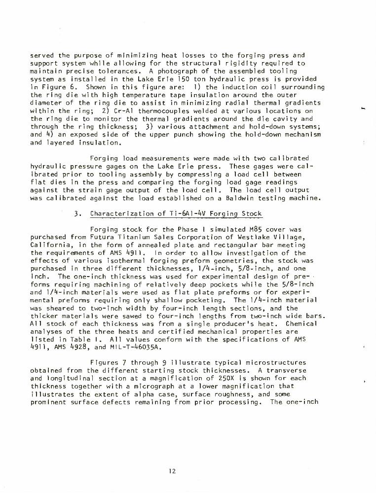
served the purpose of minimizing heat losses to the forging press and support system while allowing for the structural rigidity required to maintain precise tolerances. A photograph of the assembled tooling system as installed in the Lake Erie 150 ton hydraulic press is provided in Figure 6. Shown in this figure are: 1) the induction coil surrounding the ring die with high temperature tape insulation around the outer diameter of the ring die to assist in minimizing radial thermal gradients within the ring; 2) Cr-Al thermocouples welded at various locations on the ring die to monitor the thermal gradients around the die cavity and through the ring thickness; 3) various attachment and hold-down systems; and 4) an exposed side of the upper punch showing the hold-down mechanism and layered insulation.
Forging load measurements were made with two calibrated hydraulic pressure gages on the Lake Erie press. These gages were cal- ibrated prior to tooling assembly by compressing a load cell between flat dies in the press and comparing the forging load gage readings against the strain gage output of the load cell. The load cell output was calibrated against the load established on a Baldwin testing machine.
3. Characterization of TJ-6A1-4V Forging Stock
Forging stock for the Phase I simulated M85 cover was purchased from Futura Titanium Sales Corporation of Westlake Village, California, in the form of annealed plate and rectangular bar meeting the requirements of AMS 4911. In order to allow investigation of the effects of various isothermal forging preform geometries, the stock was purchased in three different thicknesses, 1/4-inch, 5/8-inch, and one inch. The one-inch thickness was used for experimental design of pre- forms requiring machining of relatively deep pockets while the 5/8-inch and 1/4-inch materials were used as flat plate preforms or for experi- mental preforms requiring only shallow pocketing. The 1/4-inch material was sheared to two-inch width by four-inch length sections, and the thicker materials were sawed to four-inch lengths from two-inch wide bars. All stock of each thickness was from a single producer's heat. Chemical analyses of the three heats and certified mechanical properties are listed in Table I. All values conform with the specifications of AMS 4911, AMS 4928, and MIL-T-46035A.
Figures 7 through 9 illustrate typical microstructures obtained from the different starting stock thicknesses. A transverse and longitudinal section at a magnification of 250X is shown for each thickness together with a micrograph at a lower magnification that illustrates the extent of alpha case, surface roughness, and some prominent surface defects remaining from prior processing. The one-inch
12
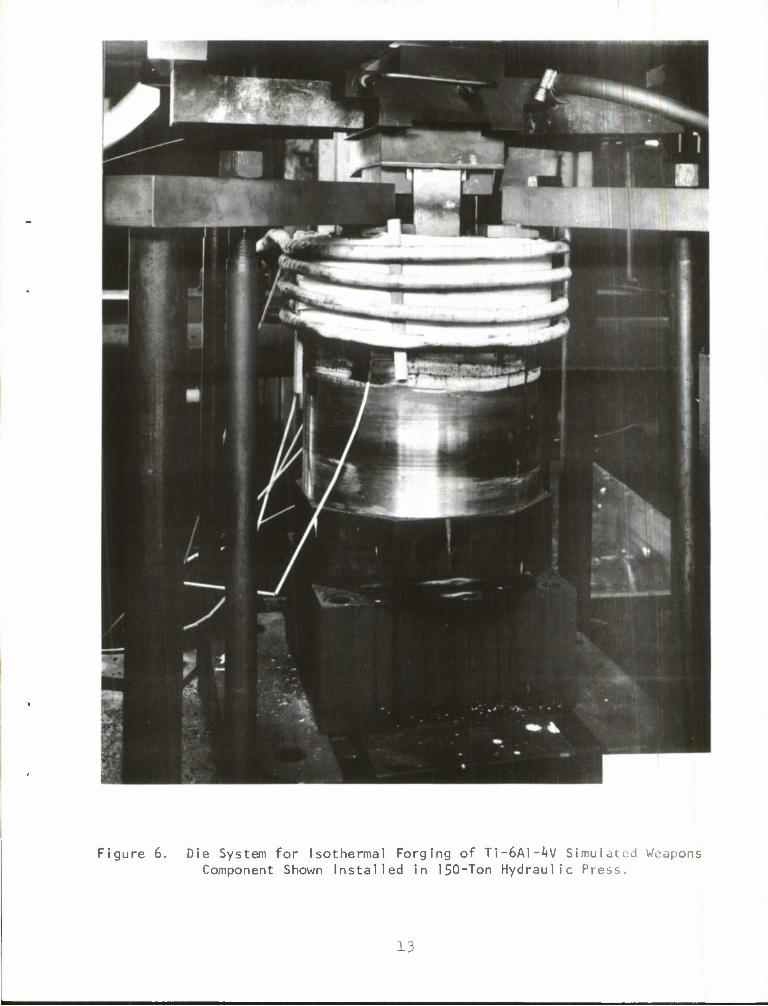
Figure 6. Die System for Isothermal Forging of Ti-6A1-4V Simulated Weapons Component Shown Installed in 150-Ton Hydraulic Press.
13

<
U- O
CO GO _l UJ < — — h- of 0£ \- UJ CL ca O z CC — O- 0
Q: _J O < u. <_> — _i z < $ I ee <_> UJ UJ 3: 2: 1-
0 Q CO z •H
< oo UJ UJ GO CO >• < _1 I < Q. z < ce
0 _l u. < CJ m — 0 3: 0 UJ 1- -x. co <_>
> Q -3- UJ 1 — 1—
u. < — NO h- 1 cc •— UJ 1- <_>
1_ <D Q. O L_
O-
1 T3 l/l 0 O O
O L- l/l • • • CC TO t) 0 .— CM
3: c -a- J- •J-
0 O ! < • • • a: e'- O o\
en J" CO
cn c CN in O LT\
0 e*e • • • *— c CM 1— CN| UJ
JZ U *-> O O O .— cr> in O O •— c cn OO O l/> <u m n * c u r- O LA 0) 4-J -3- -3" -3-
-C 4-1
-0 cn ^~ c <D (D .— L. > •M
CO
in
TO c <
TO O
i o
CNl o
04
CNI z
o o o LTl CA
H) —
O o 00
IN. CN
o o LA
rA CA
TO TO TO CO cc CO
cn 0 NO OO 0 «— .— • • • 0 O O
^_ »— OO NO O O O O O O • • * O O O
OO NO .— O O • • • -3" -a- -3"
CT» CNI <— cn CA • • • NO LA NO
_ O m ^— — •—
O O 0 • • •
O O O
^ OO CM »— CNI *— • • • O O 0
CM O CNI cn CNI CN| 0 O O
LA CN|
o O
O o o o CA
o O o o CNI
TO CD
O CNI
LA
1 O
O
0 LA
O LA
o LA
LA
LA vO
LA O
O cn
CO O
<D c
4-> • >-< CO CM TO O -0 1 4-> O 4-> O 0) z <D LA 0) cn 0) CA :r — CNI E CA £ co
0) 0 •— 1 •— 1 1- — H- O h- 0
1 l/> — 0 l/l
4-J •— <D TO JZ c 2: 1-
00
LA
OO
fc — z — UJ cn x -a- UJ
co — ? =>. < o»
E
E
E
_E X TO 2;
14

Longitudinal Section 250X
b. Transverse Section 250X
Figure 7. Photomicrographs Depicting the Microstructure of the 1-Inch Thick Ti-6A1-^V Alloy Isothermal Forging Stock in the As-Received Condition.
15

c. Transverse Section Illustrating Surface Condition 75X
Figure 7. Continued.
16
a. Longitudinal Section 250X
Transverse Section 250X
Transverse Section Illustrating Surface Condition 100X
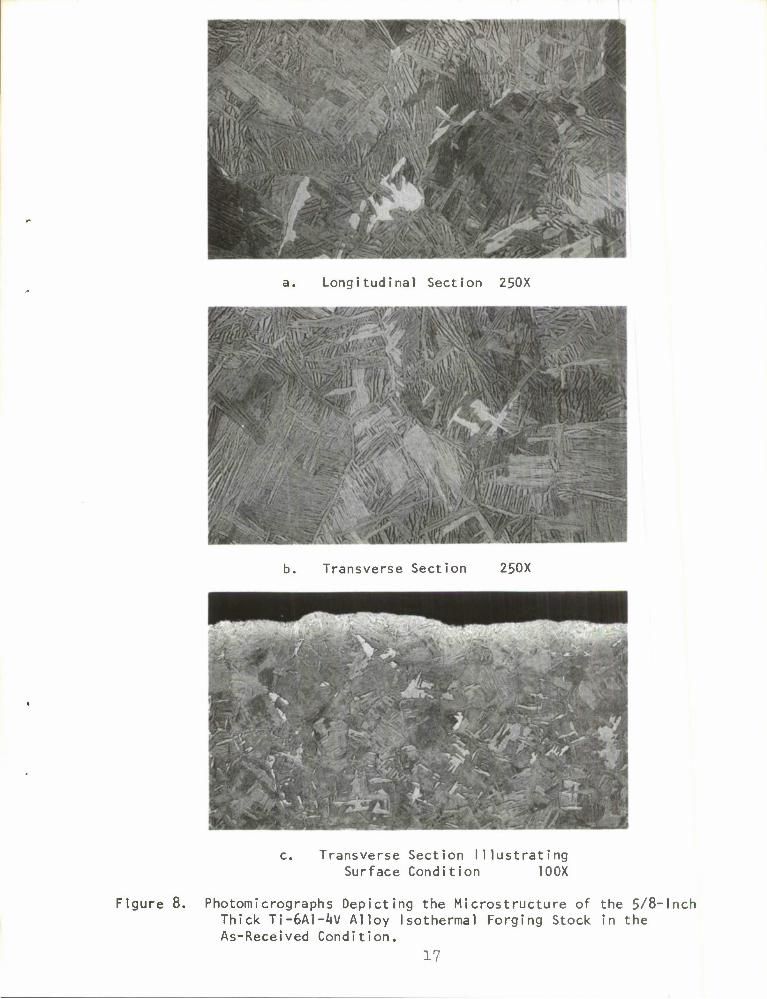
Figure 8. Photomicrographs Depicting the Microstructure of the 5/8-Inch Thick Ti-6A1-^V Alloy Isothermal Forging Stock in the As-Received Condition.
17

a. Longitudinal Section 250X
b. Transverse Section 250X
c. Transverse Section Illustrating Surface Condition. 100X
Figure 9- Photomicrographs Depicting the Microstructure of the lM-lnch Thick Ti-Al-4V Alloy Isothermal Forging Stock in the As-Received Condition.

thick material exhibits a microstructure, Figure 7a and b, consisting primarily of equiaxed primary alpha grains in a fine transformed beta matrix typical of the annealed structure obtained after processing below the beta transus temperature. Some acicular primary alpha is also observed in various locations presumably caused by inhomogeneities in temperature and flmount of deformation in the rolling process. The structure of the annealed one-fourth-inch plate, Figure 9a and b, is primarily acicular alpha but otherwise Is similar to the one-inch material in that processing was also apparently below the beta transus. Th» microstructure of the five-eighth-inch thick material, Figure 8a and b, is radically different. This "basket weave" microstructure is typical of material cooled from a temperature high in the beta field and represents a structure that has been shown to be high in toughness and creep resistance but less than optimum in ducti1ity.(10)
The low magnification micrographs in Figures 7c, 8c, and 9c demonstrate the extent of alpha case remaining from processing. The approximate depth of alpha case for the three material thicknesses are 0.008-inch for the one-inch material, 0.002-inch for the five-eighth- inch material, and O.OO^-inch for the one-fourth-inch plate. Several pieces of the one-inch thick material had a longitudinal seam resulting from the rolling process extending to a maximum depth of 0.040-inch as also shown in Figure 7c. All oxidized and defective surface material was removed as a preliminary step in machining of the experimental preforms. In commercial forging practice such stock removal would normally be accomplished by chemical means.
B. First Iteration Isothermal Forging
As described previously, the major difficulties anticipated in the manufacture of the M85 cover by isothermal forging are in the areas of preform design, lubrication and hot die system performance. The program of forging the subscale simulated components was therefore conducted in two forging iterations to efficiently investigate effects of process parameters relating to these variables. The first iteration was directed primarily toward establishing the required conditions of temperature, pressure and dwell time which would produce breakage, and investigating the effects of various types of preform design. The second iteration continued the preform optimization scheme with further concen- tration on determination of mechanical properties, dimensional accuracy and reproducibi1ity, and lubrication variations. The two forging iterations are described in the following report sections.
(10) Titanium Metals Corporation of America, "Properties of Ti-6A1-^V," Titanium Engineering Bulletin Number 1, February 1965•
19

I. Preform Design
One of the major difficulties in isothermal forging of the M85 cover is that of establishing the proper initial stock distribution required to achieve the vertical fill requirements of the various projections and side ribs without encouraging the generation of defects such as laps and seams In the finished forging. The initial iteration in the Phase I schedule of forging trials was designed to evaluate the effects of preform design on these filling characteristics. The types of preforms planned for investigation Included flat plates, a single-pocketed, plate-like shape, a double-pocketed plate, a double- pocketed shape with a streamlined rib arranged to account for the volume of the projection, and an edge notched plate preform designed to supply a fresh quantity of lubricant to the ribs as they are filling. In total, four different types of preforms were considered. Two of each type were designed with different values of radii and initial rib heights. Since the isothermal forging die design for the Phase I simulated component has no requirement for excess material to be removed as flash, careful volume control is required for the preform to arrive at a specific value for web thickness. The preform design was therefore made on the basis of maintaining the cross-sectional area of the preform equal to the cross section of the finished part for a preselected target web thickness at several stations along the part length. This procedure was violated, of course, in those preforms that had no additional stock allowed to account for the projection volume as, for example, the flat plates. This provided a significant test of the relative amounts of longitudinal and transverse flow that can be obtained in isothermal forging. Figures 10 through 13 illustrate top and bottom views of the machined preforms after blasting with fine grained zircon sand prior to precoat lubricant application for forging.
The overall length and width dimensions of all preforms were 3.955 t0.005"inches and 1.955 ±0.005"inches, respectively. The clearance between the preform and the sides of the ring die with the die at 1650°F and the preform at 1300°F is thus 0.028 "inches/side in the width direction and 0.035"inches/side in the length direction (these numbers are based on thermal expansion coefficients of 5.7 x 10~° in/in/°F for TI-6AI-AV and 8.8 x 10"6 in/in/°F for IN-100 and a lubricant thickness of 0.002-inches per side).
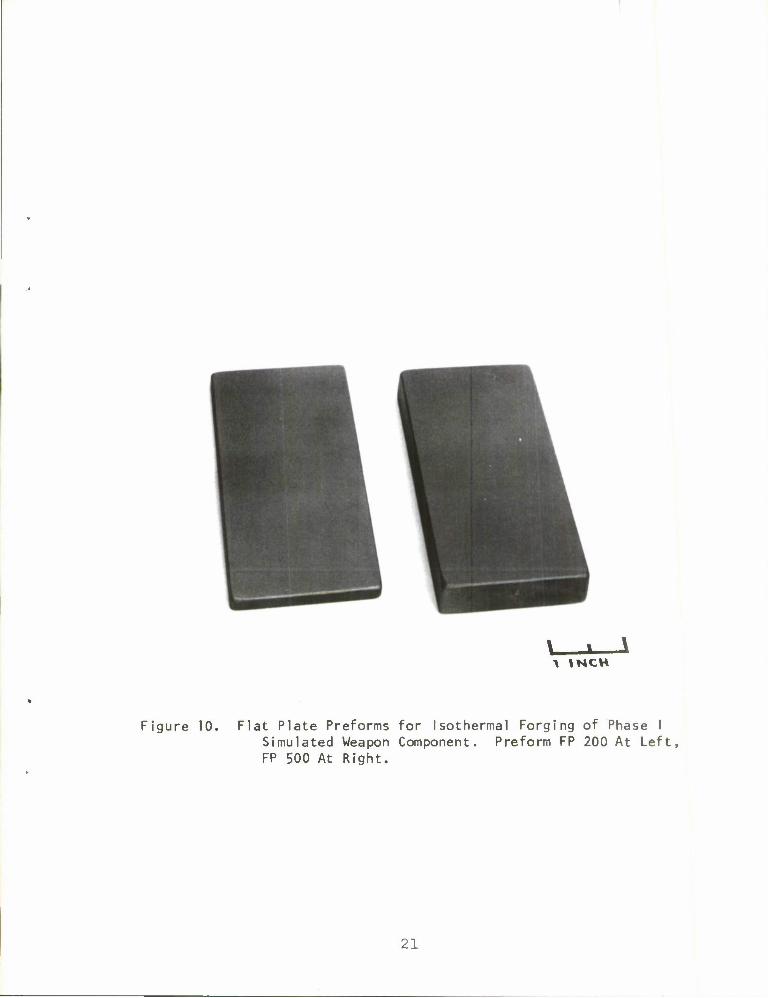
Figure 10 illustrates the two flat plate preforms. These were made in two initial thicknesses, 0.200-inches and 0.500-inches. Three pieces of each thickness were ground to size. These preforms were used during initial isothermal forging efforts to establish the extent of fill and surface conditions obtained under variable conditions of temperature, pressure, and dwell time.
20
1 \NCH
Figure 10. Flat Plate Preforms for Isothermal Forging of Phase I Simulated Weapon Component. Preform FP 200 At Left, FP 500 At Right.
21

A INCH
a. Preform DR 1000
b. Preform DR 750
Figure 11. Top and Bottom Views of "Double-Radiused" Preforms for Isothermal Forging of Phase I Simulated Weapon Component.
22

a. Preform SR 500
b. Preform SR 1000
Figure 12. Top and Bottom Views of "Single-Radiused" Preforms for Isothermal Forging of Phase I Simulated Weapon Component.
23
1 I NCH
a. Preform AF 583
b. Preform AR 566
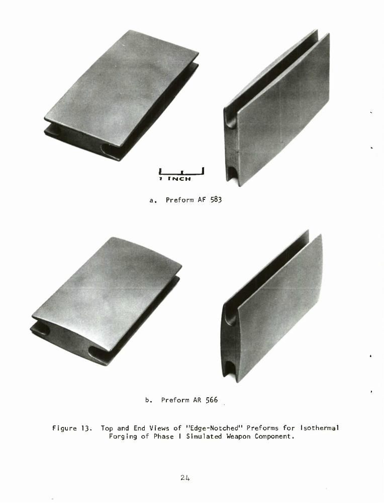
Figure 13. Top and End Views of "Edge-Notched" Preforms for Isothermal Forging of Phase I Simulated Weapon Component.
2k

Figure 11 illustrates two typical "dog-bone" preforms. The code designation for these preforms is "DR" for double-radius since the pieces were machined with a flat web portion joined to partially filled ribs by gently radlused fillets. The two different preforms represent different fillet radii and preform web thicknesses and therefore corresponded to different target web thicknesses in the finished forging. This type of preform Is quite conventional and represents a typical approach to achieving fill in rib and web structural forging as in aircraft components made by conventional forging processes.
The third preform type is the "single radius" (SR) shape illustrated in Figure 12. This preform also has partially filled ribs but these are joined by a web formed to the contour of a large radius. Cross sectional areas of these preforms were designed to consider two alternate deformation modes. In preform SR 1000 the target web thickness Is less than the starting minimum web thickness, while for SR 500 the web thickness at completion of rib fill is greater than the minimum web thickness in the preform.
The last preforms as shown in Figure 13 were designed in an unconventional manner in an attempt to provide improved rib fill capability. In this preform notches were prepared along the full length of each edge of the stock. The reasoning that led to the evaluation of this design was that in forming the ribs of an H-shaped structural forging with a conventional preform, the flow pattern of material entering the ribs must divide near the centerline of the web into separate volumes to fill the upper and lower ribs, respectively. In this process some fresh surface material may emerge at the web centerline without a lubricant coating. The resulting high friction conditions could result in some difficulty in achieving complete rib fill. With a conventional preform also, a dead metal zone may possibly arise at the intersection of the web with the ribs. This dead metal zone by its lack of deformation could affect the microstructure in the subsurface region of the rib-web junction. The edge notched preform design provides a test of these possibilities in that a fresh lubricant film will always be supplied from within the notch and the material from the hypothetical dead metal zone is absent providing for increased homogeneity of deformation.
Preform AF 583 (Figure 13) is tapered in the longitudinal direction to account for the required projection volume, but the upper and lower preform surfaces are flat and parallel In the transverse direction. This taper was designed to provide a test of the effects of the lubricant on surface finish as any entrapment of lubricant on a flat surface can result in a localized depression in the finished part. Preform AR 566 is not tapered longitudinally, but is gently radiused on the upper and lower surfaces in order that on deformation a roughly "V" shaped channel will spread the lubricant film uniformly over the web surfaces.
25

2. Lubrication
One of the most severe problems in isothermal forging of titanium, and possibly the problem least amenable to quantitative description, involves formulation of effective lubricants. Conventional forging die lubricants boil, decompose, or react with hot dies, and therefore cannot be employed. For isothermal precision forging of titanium alloys, the requirements of practical lubricants are that they provide:
1. Low interfacial friction to minimize forging loads.
2. Good film strength, particularly at corner radii, to minimize the natural tendency for titanium to "gall" to other metals.
3. An interface to prevent diffusion bonding between the workpiece and the die during the dwell at the bottom of the stroke.
k. Protection of the titanium alloy workpiece from interstitial contamination during heating and forging.
In addition, the lubricant must be inert (nonreactive) with the workpiece and the die materials and it must be formulated and applied in such a manner as to leave no cavity-clogging or surface-fouling residues on the dies themselves.
Lubricants employed at TRW Materials Technology for isothermal forging of titanium alloys have been formulated with all of these require- ments in mind and have resulted from a great deal of experimental effort. Early experiments revealed that boundary film lubricants such as graphite or boron nitride do not promote significant metal flow in thin sections, and that hydrodynamic "squeeze film" lubricants such as glasses reduce friction sufficiently to allow the metal to flow into thin cavities, but invariably also build up in the cavity extremities. TRW lubricants for isothermal forging of titanium are of the hydrodynamic type, but are "filled" with graphite or boron nitride powders to afford release without sticking. The filler material makes up a fairly large fraction of the coating volume, each filler particle being in effect "coated" with glass for oxidation protection and coherence, but under pressure the filler material is released to act as a friction reducer and separating compound.
The effectiveness of this type of lubricant has been found to be fairly sensitive to both isothermal forging die temperature and the type of preheat cycle employed as described in the next section.
26

3. Experimental Forging Trials
A set of sixteen Phase I simulated component forgings was produced with the isothermal forging tooling described previously. This report section outlines the procedure utilized in making the forgings. Some preliminary comments on the results are provided in a subsequent section.
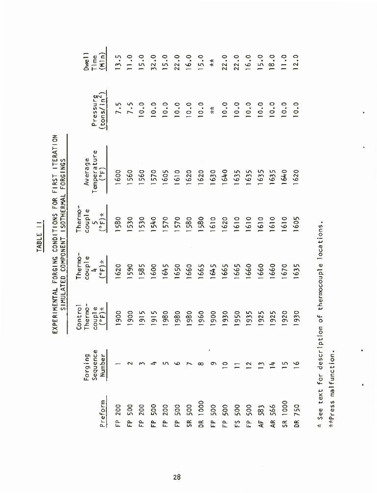
The sixteen forgings were produced under the temperature, pressure and time conditions listed in Table II. The general procedure prior to the forging operation in all cases included: dipping the sandblasted preform in a lubricant slurry to form a uniform coating; drying the coating for a minimum of ten minutes in a recirculating air oven at 120°F; preheating the coated preform for ten minutes at 1300°F to partially fuse the coating and to minimize thermal shock on entering the die cavity; heating the preform between the heated dies for ten minutes with no load applied, to achieve an equilibrium temperature in the preform and also to allow the punches to regain the heat lost during the separation for part insertion.
The conditions 1 isted in Table I I include the control temperature, i.e., the temperature at the outside of the ring die that was used to control the application of induction heating power, the temperatures measured by thermocouples numbered k and 5 located at the center of the short side and center of the long side of the ring die slot, respectively, the nominal temperature, taken as the average between these readings; the applied forging pressure; and the total dwell time under pressure used for the isothermal forging operation. In experimental forgings numbers 1 through 8, the forging dwell time variable was pre-established at various levels to examine the effects of this variable. Deformation rates were recorded with a dial indicator to allow comparisons at equivalent reductions. Dwell times were kept small at first to minimize the possibil ity of tool ing damage. Measurement of the major forging dimensions after removal from the dies confirmed that little or no enlargement of the ring die cavity was taking place and therefore in subsequent forging operations the dwell under full applied load was maintained until the rate of movement of the press ram fell to less than 0.003-in/min. The movement of the ram was measured with a dial indicator graduated in 0.001-inch increments, and dial gage readings were manually recorded at regular intervals during the dwell, in order to establish the instantaneous deformation rate.
b. Evaluation of Isothermal Forgings
Evaluation of the 16 isothermal forgings produced in the first iteration was primarily visual. A detailed examination of dimensions, microstructure, mechanical properties and non-destructive testing was performed on parts from the second forging sequence.
27
c LA O o O O O O O o O O O O O o
a~ CO •— LA rsi LA CM vO LA •i' CM CM vO LA CO — CM
— — — PA "" CM — — CM CM
CO <
< LU </) I- (3
I- cj CO CC° DC O
LL. CC LU
co a: z t- o o — CO
z z O LU o z
o C9 a. z z: — o « o en O Q
-I < < -I
zg LU — X CO
DC LU Q_ X
^^ OXM i_ c 3 •~ in v. in V) 0) c L- O
O- *J •—*
LA LA O O O
r~. r-~ o o o
o o o
o o o * o o o
o o o
o o
o o
o o
o o
<u 1_
a) 3 Dl 4-> (D ro —- i_ L- u. <U <D o > a.^— < g
i-
OOOOLAOOOOOLALALALA OvOMDr-«0.— CMCMPA-3-PAPAPAPA \OLALALA\0\OvO\OMDvOvOvO\OvO
o 3
o CM vO
I o <u E "^ * i_ a. *~« fl) 3 LA u. -c o o I- u *—
Q <U u "D.
£ ° I- o
o o o o CO PA CA -3" LA LA LA LA
c r-» LA
o o o o N OO (O - LA LA LA vO
O O O O O O LA CM ~ — — — — O vD vO VO VO MD VO VO
OOLAOLAOOLA CM CA CO 0-3" LAvOvO SO LALAvOvOvOvOvO
LALALAO OOOLA -3<VOVOVOVONO I—. PA VO \0 NO VD VO VO VO VO
o -c CJ h-
O 4> -X
1_ "o-IZ fl) 3 o
o
OOLALAOOOO oo — — cococovo CACACACACACACACA
OOOLALALAOO OPALAPACMCMCMPA CACACACACACACACA
in c o
O O
a. 3 o o
<1)
c o
<u m U i_ c c <u •— a> X) en 3 F l_ a 3 o <u Z
Li- CO
— CM PA -3" LA MD CO CAO — CM PA-3" LAvO
1_ O
T3
C O
c 3
F o O •u in u o o O o O o O o O o o O CA vO o o U1
n o O O o o o O O O o o O CO vO o LA d) a) 4- CM LA CM LA rvi LA LA ,— LA LA LA LA LA LA _- r»» <D L- 0) CO a. L_ Q. O- a. Q- o_ CL ac rr- CL. a. CO Q- u. CC cc Oi -!:
Q- LL. U_ u_ U. u_ U- LO Q u. u. U- LL < < CO Q -;; -i:
28

Figures ]k and 15 illustrate two simulated component forgings in the as-forged condition. The dark coating on these pieces is the forging lubricant that remained on the parts following the Isothermal forging treatment. In all but one forging, the lubricant performed excellently in providing a uniform film throughout forging and thus pre- vented metal-to-metal contact between the workpiece and dies. In only one case, preform OR 1000, was difficulty obtained in removing the piece from the tooling. With this preform, a lap formed on the punch surface adjacent to the projection. The freshly uncovered titanium alloy surface had no coating to separate it from the IN-100 punch and therefore it "diffusion-bonded" to some degree and proved difficult to eject from the die cavity. In the process several bolts on the clamps that held the punch to the ram fractured. The tooling was subsequently cooled and disassembled, the bolts were replaced, and an examination and a general refurbishing of the punches was accomplished. Lubricant accumulation noted after the first eight forgings was slight. Some regrinding of the upper punch surface was necessary to remove the titanium remaining from the forging. After the die set was reassembled, forging of a second set of eight pieces proceeded without incident.
Photographs of several representative forgings from the first iteration were cleaned by light sandblasting. Photographs of these are supplied in Figures 16 through 18. Forgings 1 through 5 were produced from flat plate preforms at increasing values of temperature and pressure as reported in Table II. Fill, as measured by rib and projection heights, is a strong function of these variables and therefore the values of 10 tons/sq. inch and approximately 1650°F were selected as the forging parameters for all succeeding tests. Exceeding either of these limits was considered dangerous from a tooling dimensional standpoint, as the possibility e,xisted, based on calculated stresses, that enlargement of the ring die slot could occur. The overall width of each forging was measured with micrometers after each trial to determine whether or not such creep of the die was occurring, but no width increase was observed. The outside temperature of the ring die reached as high as 1980°F in achieving 1650°F in the cavity. This was also considered a limitation on temperature to avoid catastrophic oxidation of the outer ring die surface.
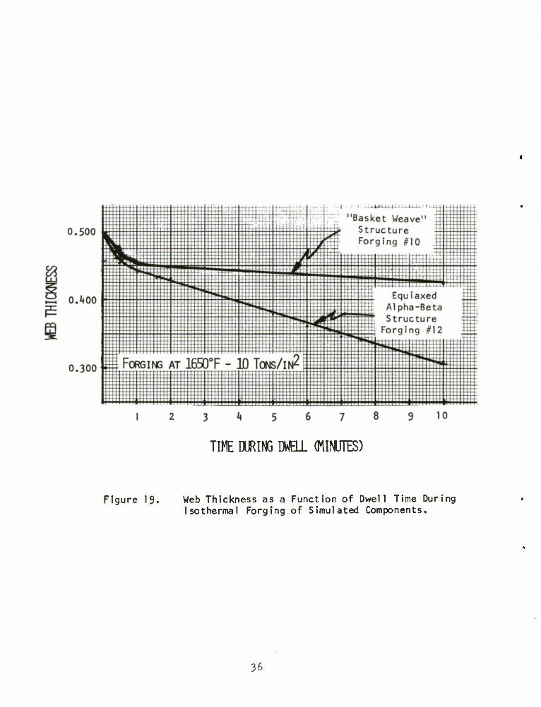
An interesting comparison on the effect of starting micro- structure on isothermal forging behavior is shown by forgings numbered FP 500-10 and FP 500-12 in Figure 17. Both were forged from flat plate preforms 0.500-inch thick under identical conditions of temperature and pressure, but the former was machined from a piece of 5/8 inch thick starting stock exhibiting the "basket weave" microstructure of Figure 8, while the latter was made from a piece of 1 inch thick stock having the equiaxed alpha structure of Figure 7. A substantial difference in fill characteristics is demonstrated, forging FP 500-12 having nearly reached complete fill while FP 500-10 has hardly begun to fill, even though it
29

I . 1
Figure 1A. Phase I Simulated Weapon Component No. FP 200-5 in the As-Forged Condition.
30

1 I 1 1 INCH
Figure 15. Phase I Simulated Weapon Component No. DR-1000-8 in the As Forged Condition
31

Punch Side a. Forging SR 500-7 Ejector Side
b. Forging DR 1000-8
Figure 16. Two Views of Isothermally Forged and Sandblasted Simulated Weapon Components.
32

Punch Side a. Forging FP 500-10 Ejector Side
b. Forging FP 500-12
Figure 17- Two Views of Isothermal1y Forged and Sandblasted Simulated Weapon Components.
33

Punch Side a. Preform AF 583 Ejector Side
b. Forging FS 500-11
Figure 18. Two Views of Isothermally Forged and Sandblasted Simulated Weapon Components.
34

had seen a significantly longer dwell time as reported in Table II. Figure 19 illustrates the rate of ram movement during the 10-minute dwell on these two forgings. A comparison of deformation rates under equivalently applied loads at equal temperature provides a striking example of the effect of microstructure. This information provided a basis for the microstructural limitation on stock procurement in the process specification discussed later.
Several important conclusions were reached based on the first iteration forging sequence. Effects such as: l) the importance of starting microstructure; 2) desirable levels of temperature, pressure and dwell time; 3) the influence of preform design on metal flow in ribs and projections; and **) the causes of several types of forging defect, were determined and provided a data base for the Phase II forging pro- cess. Also, the effectiveness of the lubricant formulation proved excellent from workpiece protection, die release and low accumulation considerations. The difficulties encountered in filling the 1/16-inch thick rib independent of draft angle, and the need for a more practical preform design concept pointed to the need for a second forging iteration before attempting manufacture of the M85 cover component.
C. Second Iteration Isothermal Forging
In the second iteration, a total of 18 simulated components were produced by isothermal forging. The principal variable during the test sequence was preform design but some efforts were made to more exactly determine the effect of temperature»and some alternative lubricant formulations were tested. Between the two iterations, the tooling was disassembled, both punches and the die ring were lightly polished and the two 1/16-inch thick ribs were ground to an opening of 0.090-inch plus draft to more precisely correspond to the conditions required in the forged cover. A forging evaluation was also conducted. This evalu- ation included visual examination, dimensional inspection, post-emulsi- fication dye penetrant inspection, sectioning for macroexamination (grain flow), depth of alpha case measurement, hardness traverses, chemical analysis, microstructural examination and mechanical property determinations. A description of the forging process and test results Is provided in the following report sections.
1 . Forging Procedure
The experimental conditions selected for the series of 18 forgings are listed in Table III, and the forgings are illustrated in Figure 20.
35
TIME DURING DWELL (MINUTES)
Figure 19. Web Thickness as a Function of Dwell Time During Isothermal Forging of Simulated Components.
36

TABLE I I I
EXPERIMENTAL CONDITIONS FOR SECOND ITERATION PHASE 1 SIMULATED WEAPONS COMPONENT ISOTHERMAL FORGINGS
Forgi No.
ng Lubricant Preform
FP550
Temperature*
1615/1690-1653
Avg. Web, in.
Preheat Cycle** (Time-Temperature-
Applied Load)
17 E-l 0.32*» 10-1300°F-0
18 11 II 1615/1675-1653 0.332 10-1300°F-0
19 E-2 II 1620/1680-1650 0.32i» 10-1300°F-0
20 11 II 1680/17^0-1710 0.333 10-1300°F-0
21 E-l II 161 5/1 680-16A7 0.321 10-l650°F-25
22 ii FT350 1585/1670-1628 0.101 10-l650°F-25
23 E-2 FP550 1610/1700-1655 0.331 10-l650°F-25
2k E-l 11 1600/1690-16A6 0.327 10-l650°F-25
25 II 1600/1 685-1 6A3 0.331 10-l650°F-25
26 II 1610/1690-1650 0.3^5 10-l650°F-0
27 " 1610/1690-1650 0.333 10-l650°F-25
28 FT550 1610/1690-1650 0.296 10-l650°F-25
29 II 1605/1675-16^0 0.291 10-l650°F-25
30 FT550X 1610/1690-1653 0.295 10-l650°F-25
31 FT350 1615/1665-16A0 0.253 10-l650°F-25
32 E-3 FT550 1605/1 675-16*40 0.3^1 10-l650°F-25
33 E-l FT550X 1 61 0/1 675-16^3 0.316 10-l650°F-25
3* 11 ET853 1620/1690-1655 0.^62 10-l650°F-25
*Temperatures (CF) listed are the maximum and minimum values recorded by CR-AL thermocouples welded to the upper ring die surface in close proximity to the central cavity.
**Preheat time (minutes), temperature (°F), and applied load (tons) on preforms before application of forging load. See text for further detail
Applied Pressure - 10 tons/in^, Dwell Time - 15 min. for all forgi ngs,
57

a. Forgings Viewed from Punch Side
b. Forgings Viewed from Ejector Side
Figure 20 Second Iteration Phase I Simulated Weapon Component Isothermal Forgings, As-Forged and Lightly Sandblasted. Note that Forgings are Arranged in Numerical Order from Left-to-Right Starting at Upper Left.
38

a. Preform Lubrication and Preheating
Preform preparation for forging consisted of a light sandblasting followed by application of a lubricant coating. The coating operation was performed by immersion of a slightly heated (120°F) preform in a slurry of the proper consistency to provide a coating thickness of 0.003-0.005-inches per surface uni- formly over the piece. Three lubricants previously developed by TRW, having the designations shown in Table III, were applied in these tests. The E-l lubricant was the one used for all prior Phase I forgings. Two additional lubricants, E-2 and E-3, which had exhibited some beneficial results in other isothermal forging applications at TRW,were evaluated in these trials.
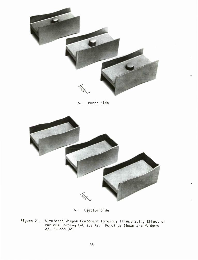
Figure 21 illustrates top and bottom views of three forgings (numbers 23, 2k and 32) produced with the three different lubricants from flat plate preforms. The extent of rib and projection fill was relatively unaffected by the lubricant formulation, but the effects on surface condition are apparent. The data listed in the last column of Table II indicate the type of preheat cycle used on each forging. This preform preheat cycle performs two basic functions. First, during this time the preform is brought to a uniform temperature close to the isothermal forging level, and second the precoat is fused in order to enhance hydrodynamic lubrication. In the first set of Phase I forgings, the preforms were heated at 1300°F for 10 minutes in an electric furnace after removal from the precoat drying oven. The pieces were then given a die preheat at 1650°F for 10 minutes between the heated punches with no load applied, to achieve an equilibrium temper-
ature in the preform and also to allow the punches to regain the heat loss during the separation for part insertion. In the second set of Phase I forgings, it was decided for several reasons to omit the 1300°F preheat step on several of the forgings and to apply a load to the preform during the die preheating step. The reasons for this are, first, it is possible that some lubricant deterioration occurs during the 1300°F preheat by oxidation and that lubricant effectiveness could be thus reduced. Second, application of a load during die heating will increase the preform heating rate, possibly resulting in a higher workpiece temperature at the start of the isothermal dwell. Third, elimination of the electric furnace preheat saves 10 minutes of the total cycle time and thus provides for a potentially increased production rate.
In general, the effect of preheat cycle on the forging dimensions and properties was found to be negligible. Since no substantial difference in rib fill was shown, the lubricant de- terioration during the 1300°F preheat must not be significant. There- fore, because of the possibility that the 1650°F die preheat under a
39
a. Punch Side
Ejector Side
Figure 21. Simulated Weapon Component Forgings Illustrating Effect of Various Forging Lubricants. Forgings Shown are Numbers 23, 2k and 32.
40

25 ton load may have contributed to the titanium pickup on the dies, it has been recommended in the preliminary process specification that the original preheat cycle be used in production forging.
b. Preform Design Effects
The preform designations in Table III correspond to the following coding system: preforms labelled "FP" are rectangular plate preforms ground to 1.950-1.960-inch width and 3.950-3.960-inch length with a thickness in mils indicated by the number appended to the letter code, i.e., FP 550 indicates a preform 0.550-inches thick; preforms labelled FT are longitudinally tapered from a central projection allowance to the ends of the piece; preform ET was a special lathe con- toured preform; and preforms with an X appended had slight longitudinal and transverse tapers to account for the side-to-side and end-to-end volume requirements of the completely filled forging. The target web thickness of these forgings was determined by the preform volume and the volume of the webs and projection of the finished forging. The web thickness in most cases was chosen to be sufficiently thick to allow machining of standard tensile specimens and subscale Charpy V-notch impact bars for evaluation of mechanical properties of iso- thermal ly forged Ti-6Al-AV. Some variations in web thickness can be observed in Table III caused by differing levels of fill and by dif- ferences in preform volumes.
Figure 22 illustrates a sequence of three forgings (numbers 29, 30 and 33) made in a test of the effects of preform design on fill. It was found during this forging sequence that slight vari- ations in stock volume distribution had a profound influence on rib fill. The preform design shown in Figure 23 can be made to provide the proper stock distribution to completely fill the die cavity. Although a slight lack of fill was exhibited in the 0.090-inch rib on the punch side of forging number 33, it is clear that a slight increase in the side taper angle (g in Figure 23) on subsequent preforms would provide sufficient material to fill the thin rib. The preform design principles applicable to this forging and also to the M85 cover forging are: 1) The proper amount of material must be provided on each side of the forging neutral planes*to allow for completion of fill simul- taneously throughout the forging. Material cannot be expected to flow across this neutral plane. 2) Longitudinal material flow does not occur to an appreciable extent, except near the ends of the forging.
*A neutral plane is a surface that divides metal flow in two directions. At the neutral plane the deformation is pure compression, while to the left of the plane flow is directed to the left and to the right the flow is directed to the right.
i»l

a. Punch Side
b. Ejector Side
Figure 22. Simulated Weapon Component Forgings Illustrating Effect of Preform Design. Forgings Shown are Numbers 29, 30 and 33.
42

Figure 23. Preform Design Utilized in Isothermal Forging of Simulated Structural Components.
43

Therefore, once complete fill is established at a forging cross section, deformation stops regardless of temperature or lubrication conditions. Longitudinal flow does occur near the end rib, however, and a volume allowance must be made in the preform to account for this effect.
2. Forging Evaluation
a. Dimensional Inspection
Results of the dimensional inspection on the sim- ulated weapons component isothermal forgings are presented in Table IV. The measurements on the forgings were made with micrometers after their removal from the hot dies and their cooling to ambient temperature. The residual forging lubricant was not removed, and, therefore, the dimen- sions measured are slightly greater than the net forging dimensions. An exception to this is the overall length dimensions of forgings 28 through 3^ which were made after a light sandblasting to remove the residual lubricant that had accumulated on the ends of the pieces and some surface irregularities.
Several features of these measurements are of in- terest. The forging width and length dimensions, for example, are larger than those of the ring die cavity presumably because of the difference in thermal expansion coefficients between Ti-6A1-W and the IN-100 die material. On heating the ring die to 1650°F, the cavity expands from its original k,000-inch length to 4.055-inches calculated on the basis of an IN-100 expansion coefficient of 8.7 x 10"° in/in°F. The forging fills the die at this size, but then shrinks at the rate of 4.7 x 10"6 in/in°F for Ti-6A1-4V, which results in a length contraction of 0.036~inches. The calculated net dimension is thus 4.019-inches, which closely agrees with the measurements reported in Table IV. For the width dimension the observed discrepancy from the cavity size is not so easily explained. On heating to 1650°F, the cavity width should become 2.028-inches, and the forging dimension on cooling to room temperature should be 2.010-inches. The widths recorded in Table IV are somewhat greater than this value,and are also larger at the center of the cavity than at the ends. This indicates a small degree of convexity or elastic bulging of the side walls. The applied forging loads are much too small to cause a deflection of this magnitude and, therefore the cavity distortion must be thermal in origin, resulting from non- uniform temperature distribution in the ring provided by the induction heating system. The variability in the overall dimensions is small enough, however, that the problem appears to be solvable by die develop- ment. That is, in full scale production efforts with a die setup of this type, the die cavity could be machined to account for
kk

TABLE IV
RESULTS OF DIMENSIONAL INSPECTION
•
OF PHASE
Width
ISOTHERMAL FORGINGS
Average Forgi ng Open Mid Closed Web Projection
No. End Length
2.022
End Length
14.023
Th ickness
0.324
Height
17 2.019 2.019 0.430
18 2.018 2.020 2.017 4.023 0.332 0.468
19 2.017 2.020 2.019 4.025 0.324 0.545
20 2.017 2.019 2.017 4.025 0.333 0.505
21 2.019 2.022 2.018 4.024 0.321 0.497
22 2.020 2.027 2.019 4.029 0.101 0.525
23 2.013 2.018 2.017 4.022 0.332 0.468
2^ 2.016 2.019 2.017 4.026 0.327 0.536
25 2.015 2.019 2.014 4.025 0.331 0.544
26 2.017 2.021 2.017 4.030 0.345 0.391
27 2.018 2.021 2.018 4.020 0.333 0.472
28 2.01*+ 2.020 2.017 4.014* 0.296 0.547
29 2.017 2.021 2.017 4.013* 0.291 0.543
30 2.012 2.019 2.016 4.014* 0.295 0.546
31 2.012 2.024 2.018 4.017* 0.253 0.120
32 2.010 2.020 2.015 4.015* 0.341 0.371
33 2.012 2.020 2.016 4.011* 0.316 0.504
34 2.015 2.025 2.018 4.014* 0.462 0.543
*Measured after light sandblasting to remove residual lubricant,
Dimensions in inches.
45
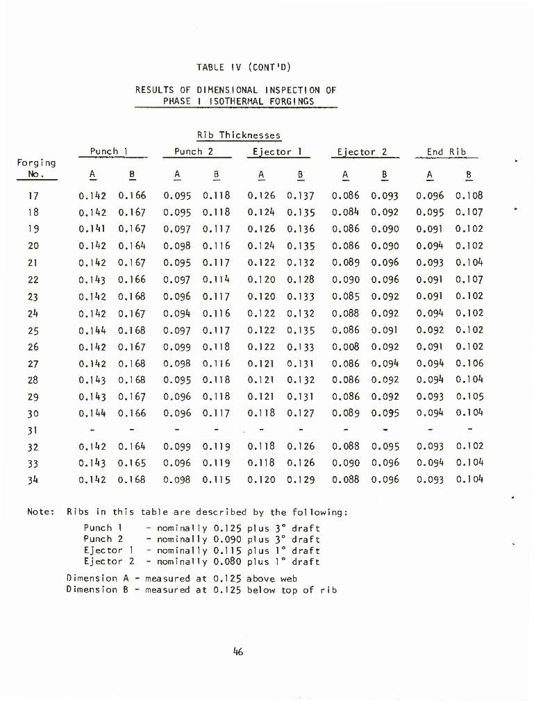
TABLE IV (CONT'D)
RESULTS OF DIMENSIONAL INSPECTION OF PHASE I ISOTHERMAL FORGINGS
Rib Thic knesses
Punc h 1 Punc h 2 Ejector 1
A B
Ejector 2
A B
End Rib Forging
No. A B_ A B_ A B_
17 0.142 0.166 0.095 0.118 0.126 0.137 0.086 0.093 0.096 0.108
18 0.142 0.167 0.095 0.118 0.124 0.135 0.084 0.092 0.095 0.107
19 0.141 0.167 0.097 0.117 0.126 0.136 0.086 0.090 0.091 0.102
20 0.142 0.164 0.098 0.116 0.124 0.135 0.086 0.090 0.094 0.102
21 0.1^2 0.167 0.095 0.117 0.122 0.132 0.089 0.096 0.093 0.104
22 0.143 0.166 0.097 0.114 0.120 0.128 0.090 0.096 0.091 0.107
23 0.142 0.168 0.096 0.117 0.120 0.133 0.085 0.092 0.091 0.102
2*4 0.142 0.167 0.094 0.116 0.122 0.132 0.088 0.092 0.094 0.102
25 0.144 0.168 0.097 0.117 0.122 0.135 0.086 0.091 0.092 0.102
26 0.142 0.167 0.099 0.118 0.122 0.133 0.008 0.092 0.091 0.102
27 0.142 0.168 0.098 0.116 0.121 0.131 0.086 0.094 0.094 0.106
28 0.143 0.168 0.095 0.118 0.121 0.132 0.086 0.092 0.094 0.104
29 0.143 0.167 0.096 0.118 0.121 0.131 0.086 0.092 0.093 0.105
30 0.144 0.166 0.096 0.117 0.118 0.127 0.089 0.095 0.094 0.104
31 - - - - - - - - - -
32 0.142 0.164 0.099 0.119 0.118 0.126 0.088 0.095 0.093 0.102
33 0.143 0.165 0.096 0.119 0.118 0.126 0.090 0.096 0.094 0.104
3* 0.142 0.168 0.098 0.115 0.120 0.129 0.088 0.096 0.093 0.104
Note: Ribs in this table are described by the following:
Punch 1 - nominally 0.125 plus 3° draft Punch 2 - nominally 0.090 plus 3° draft Ejector 1 - nominally 0.115 plus 1° draft Ejector 2 - nominally 0.080 plus 1° draft
Dimension A Dimension B
measured at 0.125 above web measured at 0.125 below top of rib
46

these d iscrepanc ies, and precision tolerances would be routinely achieved. The rib thickness dimensions listed in Table IV agree quite well with measurements of the punches as expected since thermal expansion and die distortion effects are quite negli- gible on dimensions in this size range. The variability of rib thicknesses is small, indicating that die alignment is not a serious consideration with the trap die system. The projection height dimen- sion is determined by the degree of fill in the projection and therefore is a function of preform design as shown in Figure 20.
After dimensional inspection,forgings 17 through 30 were stress relieved at 1300°F for 1 hour. Following this treatment the pieces were cleaned of residual lubricant by a light sandblasting. A random sample of 7 forgings was reinspected to determine if signi- ficant distortion or dimensional changes had occurred. Changes noted were small and were attributed mainly to removal of the residual forging coa t i ng.
b. Fluorescent Penetrant Inspection
A post-emulsification fluorescent penetrant inspection was performed on forgings 17, 23 and 27. The procedure and penetrant formulations were chosen for high sensitivity. The penetrant utilized was ZL-22, the emulsifier was ZE-3, and the developer was ZP-A, produced by Magnaflux Corporation.
Results of the inspection on the three forgings chosen were as expected in that no significant defects were observed. The forgings were inspected for cracks, laps or seams and other surface defects based on the results of the first iteration of Phase I forgings, but none of these were found. Forging number 23 showed an indication at the internal corner at the junction of the end rib with the 0.090-inch side rib, but the indication may have been an artifact of the inspection technique since the developer powder was not easily removed from the sharply radiused corners. In general, the surface quality as revealed by this inspection technique was excellent.
c. Forging Macrostructure - Grain Flow and Alpha Case
Etching to reveal metal deformation patterns in titanium alloy forgings is extremely difficult to perform with success both because of the very fine grain structure and because of the general cleanliness (i.e., the absence of a fine inclusion distribution as is found in steels). Nevertheless, some attempts at revealing the grain flow patterns were made on forgings No. 18, 19 and 22. The results of these etchings are illustrated in Figure 2k.
hi

a. Forging Number 18
b. Forging Number 19
c. Forging Number 22
Figure 2k. Macrostructures of Isothermally Forged Simulated Components Illustrating Grain Structure.
48

Forging number 19 differs only in lubricant form- ulation from forging number 18. Yet the grain pattern shown in Figure 2*»b reveals a very uniform deformation throughout the cross section in web, rib and projection alike. Some evidence of "breaking-out" or intersection of the grain flow pattern with the surface is evidenced in the heavier rib on the punch side of forging number 19. The degree of breaking out is not severe, however, and this appears to be a problem solvable by preform design if mechanical properties should show an adverse effect. It is important to note when comparing the photographs of forging 18 with 19 that although both are sectioned through the center, the viewing directions are different. That is, the photograph of forging 18 is In the direction of the closed end, while forging 19 is viewed toward the open end. For this reason it appears that left and right are reversed in the photographs.
The cross section of forging number 22 shown in Figure 2*»c illustrates a relatively uniform grain flow pattern through- out the web, ribs and projection. This forging was made to a web thickness of only 0.099-inches, and because of this thin web the forging shows a degree of distortion in the web caused by the force required to strip the piece from the punch. This effect will be potentially important in the forging of the M85 cover and therefore consideration will be given to adding draft to selected areas of the cover forging to allow ease of removal from the punch without excessive stresses on the thin web areas. The suck hole observed on the ejector side of forging 22 is not unexpected based on the previous forging results.
Before etching for macrostructural examination, these three forgings were polished and then etched in a 0.5% hydrofluoric acid solution to reveal the extent of alpha case (the hard oxygen enriched alpha titanium layer formed on the surface of titanium alloys exposed to elevated temperature in air). An average value of alpha case thickness on the surface of the forgings was: forging number 18, 0.00l8-inches, forging number 19, 0.0015-inches, and forging number 22, 0.0015-inches. This alpha case depth is a function of temperature, the time the part is held at temperature and the degree of protection afforded by the lubricant precoat. Complete removal of alpha case on critical parts can be performed by a chemical conditioning operation if desired or, alternately, a light abrading or machining could be utilized to remove the alpha case from critical areas. Consideration of these alternatives will be given in preparation for Phase II pro- duction efforts.
*»9

d. Hardness Distribution and Micros truetural Features
A 3/1 6-inch thick transverse section was taken from forgings 18 and 19 for hardness determination and microstructural examination. The sections were from the opposite half of the forgings illustrated in Figure 2k and therefore should represent material iden- tical in nature to that utilized in the macrostructural examination. Figure 25 illustrates the section taken from forging number 18 together with photomicrographs at 100X showing the structure at several locations. Figure 26 shows the same forging section, but the microstructures are shown at 250X and the Rockwell C hardness corresponding to the various hardness indentations are presented at the right. Figures 27 and 28 present similar information for the material taken from forging number 19. The forgings shown have been stress relieved by a 1300°F-1hour-air cool heat treatment, and, therefore, the hardnesses reflect the heat treated cond i tion.
Differences in hardness between the forgings are not particularly significant but there are some significant variations among various areas of the sections. Hardness is generally higher in the web and projection than in the ribs,and the thin ribs have lower values than the thick ribs. These hardness differences probably reflect differences in cooling rates from the forging temperature at the various locations in the forgings and thus may correspond to minor variations In microstructure.
Microstructures from areas corresponding closely to some of the hardness indentations are presented in Figures 25 through 29. The photomicrographs are shown at 100X magnification with a few at 250X for clarification where needed. The microstructure is generally fine grained equiaxed alpha case with a uniform matrix of transformed beta. The only exception noted is in the lower portion of the projection of forging number 18 which exhibited the basket weave microstructure thatoccurred for unexplained reasons.
e. Chemical Analysis
Chemical analyses were made on the one-inch bar stock in the as-received condition and on rib material from the rib-web junction of forging number 20. The analyses were made for interstitial element contents only because the weight percentages of the major alloying elements are unlikely to be affected by isothermal forging. Forging number 20 was chosen because it was pressed at a slightly higher than average temperature, as shown in Table I, and because some dis- coloration of the forging surface was noted after removal from the dies.
50

ft
l/l 4) >- U 4->
u D • I- oo u .— l/l O u l- U o XI .— 1 r 3
Z Dl c Ol •— c 4-J •— «J en 1_ i_ 4-J o l/> Ll- D •— *— •
— C o
0) .— c •i-> .— <0 ai O u •— O »*-
U- — c .— en
(V 0J 1- X 1_ I) X
-C o 4-J o o •—
l/> — i-J
<TJ -C
CT1 l/l 3 C o o l_ • —
-C •M 1- m
o c o o _l • —
•u> i/i u -1 1) o
in •— L-
l/l ro en > O >- •t-j
<_> rn
. LPl CM
OJ 1- 3 m
51

IAVD O IA
m ///
!&.
CM w-m rv\ r^ ci (M
in till
i/> <n o — CM (1) ^— »— ^— c
"O i_ <n -a- LT» o CM X • • • •
-3- ll\ VD LTV o (V> pr\ cvi «v"»
1— 1 1 1 1 r—-
0) LTwO r^oo ? -* o o LT\ O O O
OS • • • • r» — CM CM CM (v-i <r> rr\
— CM ct-a-
CTv
lib
i- 3
•M o 13 1_ 4-J in o 1- u
o o
M X 3
O Ol — C 1.
— to *-> > <0 L. -M
•*-> TO
l/J 3 l/l
•— l/> — ID — C
•D
C TO — X Dl 1- O o
IJ 1- o <U O
w o -o in C
— <TJ
-C c en O 3 — O 4-1
U CD OO .c u —
._ « C -Q
CO 3
/> x o in in in CM O
U) c
1- O
o m li-
ve CM
3 CD
'«<?; y#*
52

in 4) i-
3 •M
o 3 1-
4-J
LO
o l_
o
r:
o c
•)->
(ii L
4->
LO
3
— o^
CD *— C .— 1-
cn OJ u -£> O E
U- 3 z
P CD
i_ •— 4) cn r i_
•M o o u. C/l
. -C c Ol o 3 •— 0 •u \- ID
-C O H •—
U- c •— o C •— cn
•l-J m o 5" 0)
l/l X o
cn o 10 <— O i_ 4-J
o TO
• r»> CSI
cn
53
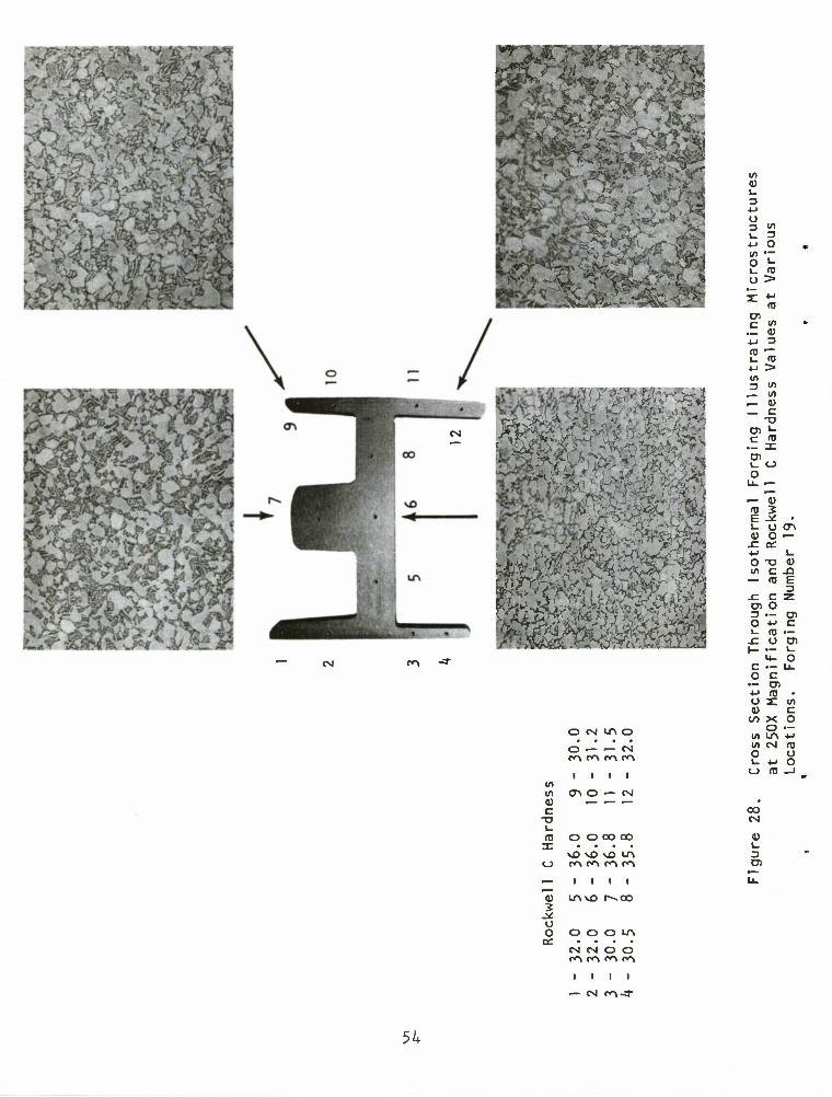
Ik. • •
CNi
f %-,
^
M- *tfy /?
^
- H S? ?#£?* :-/^(
^ SSTO
SW5 i <.V
,' £**"" 3
ONUNO
o — — CSI C\ f\ c~\ m
(/> i i I I
If) cr> o «— csi 0) ^— #— i—
c -a L. ro O O CO oo Z • • • •
\0\O\0 IA C_> co co co co
— I I i i ,— 4) LTvvD I—OO 2 -* o o O O O LA
o£ • • • • CM CM o o co co co co
1 1
— CM CO -3"
01 <U i_
O
u •1-J
O i_ o
CO
C "> .- 0)
1_ <D *J > I/)
— i/i — a> _ c O) «- C CO .- 3: Ol i_ o O
— a> co 3 E -* • u u en a> o —
O T3 m c
— CO
.c c D) O 3 — O -t-" i- co
0) -O E 3
at c
en i_ O
o a)
CO
c CD ro
X o
ul LO 01 CM O I- 4~> O CO
OO CM
U1 c o
CO o o
I-
54

200-
-o c
£, 800- •n o
400-
0- 1—I—I—I—I—I—I—I—I—I—
0 1000 2000 3000 4000
Time (Microseconds)
a. Sample Number G29-3, tested at 70°F
1200-
C
o 5- 800-
o
400-
0-
]—I—I—I—I—I—1—I—I—I—
0 1000 2000 3000 4000
Time (Microseconds)
b. Sample Number M28-4, tested at 300°F
Figure 29. Typical Oscilloscope Traces Illustrating Strain Gage and Velocity Monitoring Signals for Instrumented Charpy V-Notch Impact Tests
55

The rib-web junction is the most likely position in the forging to look for interstitial pickup because of the local deformation and thermal conditions. It was therefore felt that any deleterious effects of iso- thermal forginqs on interstitial element content would certainly be revealed by a chemical analysis of this piece. Specimens for chemical analysis were prepared in the form of plates approximately 1/16-inch thick by 1-inch wide by 2-inches long from which 3/16-inch diameter punchings were removed from the area of interest. The plates were machined to final thickness on a shaper utilizing a high speed steel cutter without coolant. Such a procedure is preferred because it minimizes the possibility of interstitial pickup from carbide cutters, grinding wheels or coolants.
Techniques of chemical analysis were:
Hydrogen - vacuum fusion,
Oxygen - inert gas fusion,
Carbon - oxygen combustion,
and Nitrogen - Kjeldahl method of wet analysis.
The results of the chemical analysis are reported in Table V which compares vendor analysis and TRW analysis of the bar material, and TRW analysis of the forging with the maximum allowable levels of the applicable AMS specification. Results shown in this table indicate a slight increase in hydrogen content, no change in oxygen level, a slight carbon pickup and a minor loss of nitrogen. Since the changes noted are slight and the absolute values of the interstitial element contents are well within the allowable limits of the specification, it is concluded that the effect of isothermal forging on chemical composition is negl ig ible.
f. Mechanical Properties
Forgings numbered 2h and 25 were sectioned for determination of room temperature and 300°F tensile properties while forgings 26, 28 and 29 were sectioned for Charpy V-notch impact testing at -^0oF, room temper- ature and 300°F.
In addition, room temperature tensile tests were performed on forgings 10 and 11 of the first iteration simulated component forgings to determine the effect on tensile properties of a stress relief at 1300°F for one hour followed by air cooling. These two forgings as described previously were made under identical isothermal forging con- ditions but from material having two different microstructures. Forging number 10 was from material exhibiting the "basket weave" microstructure, while 11 was from Ti-6A1-4V having the more desirable equiaxed structure.
56

TABLE V
EFFECT OF ISOTHERMAL FORGING ON INTERSTITIAL ELEMENT CONCENTRATION
Bar Stock Forging #20 AMS kSU
Vendor TRW TRW Maximum
Hydrogen* 0.006 0.0078 0.0099 0.015
Oxygen 0.18 0.19 0.19 0.20
Carbon 0.022 0.022 0.023 0.080
Nitrogen 0.013 0.012 0.010 0.050
*A11 compositions are in percent by weight.
57

The tensile specimens were ASTM standard cylindrical specimens with a gages length of 0.6^0-inches and gage diameter of 0.160 inches and were sectioned with their axes parallel to the long forging direction. The Charpy bars were subscale specimens 2.165 inches long by 0.197-inches thick and 0.197-inches wide with a "below notch" thickness of 0.158-inches and notch radius of 0.010-inches. In all impact bars the notch was cut perpendicular to the punch side web surface. The specimen sectioning procedure involved first cutting away all rib and projection material and then cutting the specimen blanks according to the following numbering scheme. Specimen numbers reflect the position of the blank in the forging; the blanks are numbered in ascending order from left to right as the forging is viewed from the open end with the punch side up.
Specimen numbers 1 and 2 were removed from the open-end half while 5 and 6 were taken from the closed-end half. Specimen numbers 1 and k were taken from the outer extremity of the web while numbers 2 and 3 represented material from the center of the web.
The results of the tensile tests are presented in Table VI. The data illustrate some significant variations in tensile properties with microstructure, test temperature, forging location and heat treatment. The microstructural variation is apparent from a comparison of the data for forgings 10 and 11. The yield strength and ductility as measured by reduction in area are both lower for the basketweave structure of forging number 10. The stress relief treatment tends to raise the yield strength with little effect on tensile strength and ductility as might be anticipated on the basis of residual stress considerations. Forging location has a relatively minor effect, but shows a slight tendency toward higher tensile and yield strengths near the forging longitudinal centerline with lower values near the ribs. This effect is so small however that it is not considered significant. The elevated temperature properties of the isothermal1y forged material are virtually identical to properties of conventionally processed Ti-6A1-l»V. For example, the ratio of 300°F ultimate tensile strength to room temperature ultimate strength ranged from Sk% to 86% in forgings 2k and 25. An average of 16 tests on conventionally processed Ti-6A1-4V material resulted in an average value of 84.0%. 00 Yield strength ratios for isothermally forged material varied from 79 to 8l% while 16 tests on conventional stock provided an average ratio of 79.k%.
(11) D.J. Maykuth, D.J. et.al., "Ti-6A1-4V Handbook," Defense Metals Information Center, Battelle Memorial Institute, AFML Contract F33615-71-C-1067, February 1971.
58

TABLE VI
•
EFFECT OF ISOTHERMAL FORGING ON ROOM AND ELEVATED TEMPERATURE TENSILE PROPERTIES OF Ti-6A1 -4V
Specimen Test Number Temperature
Ultimate 0 Tensile Str.
.2% Offset /ield Str. Elongation RA
10A1* 10A2
RT RT
142.6 144.6
128.0 130.5
16.3 16.1
33.4 36.4
* 10B3 10B4
RT RT
141.5 143.9
123.3 126.2
15.9 15.9
36.3 34.8
11A1 11A2
RT RT
149.3 148.0
139.1 138.4
17.5 16.2
44.6 42.7
11B3 11B4
RT RT
150.9 150.8
136.7 136.9
16.7 17.3
44.7 44.1
24-1 24-2
RT RT
138.4 140.5
132.1 133.2
19.9 20.3
46.2 46.9
25-4 25-5
RT RT
145.3 146.7
136.4 137.2
20.1 19.0
45.9 47.4
24-5 24-6
300 300
116.9 118.9
103.7 107.3
19.7 19.3
53.6 55.6
25-5 25-6
300 300
124.3 123.6
110.4 108.7
21.5 20.6
54.4 52.2
Vendor Cert if icat ion (1" Stock)
RT 145.0 133.5 12.5 39.1
• AMS 4911 Requ irement (Minimums)
RT 130.0 120.0 10.0 25.0
Steel Cover Spec ification
RT 130-150 120-135
^Specimens designated with A were stress relieved 1 hr at 1300 F, specimens designated with B were tested as-forged.
Stresses in KSI.
59

g. Instrumented Charpy V-Notch Impact Tests" ^'
Four longitudinal Charpy specimens were sectioned from each of three Phase I simulated component forgings. Six additional longitudinal samples were machined from the as-received bar stock utilized in producing the isothermal forgings. The objective of the testing was to determine the effects of isothermal deformation on the impact properties of Ti-6A1-^V. Since the forgings were insuffi- cient in web thickness to provide a standard cross section Charpy bar (0.36V1 x 0.36V'), it was necessary to use a subscale specimen (0.197" x 0.197" x 2.165") for impact testing. The availability of instrumented Charpy equipment at Rock Island Arsenal provided the means for achieving the maximum sensitivity in the test program and therefore samples were submitted to Rock Island for testing.
The three forgings selected were numbers 26, 28 and 29. Two of the forgings, numbers 28 and 29 were made under virtually identical forging conditions while number 26 was forged with a lesser total web thickness reduction (37% vs. kG% for forgings 28 and 29). Specimens were cut in the longitudinal direction, notched perpendicular to the upper web surface and numbered in ascending order from left to right as the forging is viewed from the closed end with the projection side up. Impact tests were performed at three test temperatures, -40°F, room temperature, and 300°F in accordance with the requirements of MIL-T-J46035 applicable to the M85 cover as currently fabricated from 4130 steel. However, since subscale samples were utilized, the results must not be assessed by comparison with reported impact results but rather should be compared among themselves. To make the testing as consistent as possible some care was taken to insure that several sources of variability were taken into account. These sources of variability included location within the forging, forging-to-forging differences as would be expected between forgings having slightly different re- ductions, and normal testing variability. Four tests were performed on forging 29 at 70°F to establish this latter variability. One additional test was performed to estimate the relation of the instrumented Charpy impact energy to that measured by a standard machine.
The data from the instrumented tests were recorded in the form of Polaroid photographs of oscilloscope traces showing load vs. time and velocity vs. time for the strain-gage equipped tup. An example trace is supplied in Figure 29. Measurements on these photo- graphs provided load at offset yield (Pgy) maximum load, time to maximum load, and time to rupture. The specimen dimensions, material properties, oscilloscope conversion factors (generally 200 pounds per division for the load scale and 500 microseconds per division on the time scale), and photograph measurements were combined in using standard equations to provide numerical values for the yield strength ay and impact energy.
(12)' Testing and data analysis performed under the direction of Mr. F. Anderson, Rock Island Arsenal. Reported by personal communication, February 197**.
60

Some data from the photograph measurements and results of the calculations are presented in Table VII. Figure 30 illustrates these data in graphical form, showing impact energy against test temperature. The data demonstrate that impact energy shows a relatively high scatter not clearly associated with forging-to-forging or specimen location variability. The isothermally forged material tends to have a higher impact energy than the raw stock, but the sample size is not large enough to draw statistically significant conclusions. The curves drawn through the data approximately predict the impact energy behavior at temperatures between the test temperatures. The data themselves do not preclude the possible existence of a ductile to brittle transition at a temperature greater than 70°F, but prior experiments with titanium alloys(l3) demonstrate that a typical impact energy curve generally has a shape similar to that shown in Figure 30.
D. Summary of Phase I Accomplishments
The objectives of the Phase I work were achieved. A list of some of the major accomplishments is provided in the following:
1. The mechanical properties of isothermally forged Ti- 6AI-J4V components range from slightly inferior to somewhat better than those of conventionally processed material. In all cases tested, the mechanical properties significantly exceeded the requirements for the titanium alloy and for the steel typically used in cover manufacture.
2. An original technique for designing preforms for isothermal forging was developed, tested and found to be both easily accomplished in design and reasonably successful in forging practice. The preforms are of a form that should be inexpensive to manufacture in quantity.
3. The lubricants developed by TRW in recently completed programs on turbine component forgings perform adequately in manufacture of structural components. Improvements on these lubricants with regard to decreased interfacial friction tend to cause problems with galling and accumulation. Therefore, the original lubricant formulation will be used for M85 cover manufacture.
(13) Battelle Memorial Institute Compilation of Available Information on TJ-6A1-V Alloy. Titanium Metallurgical Laboratory, Battelle, February 28, 1958.
61
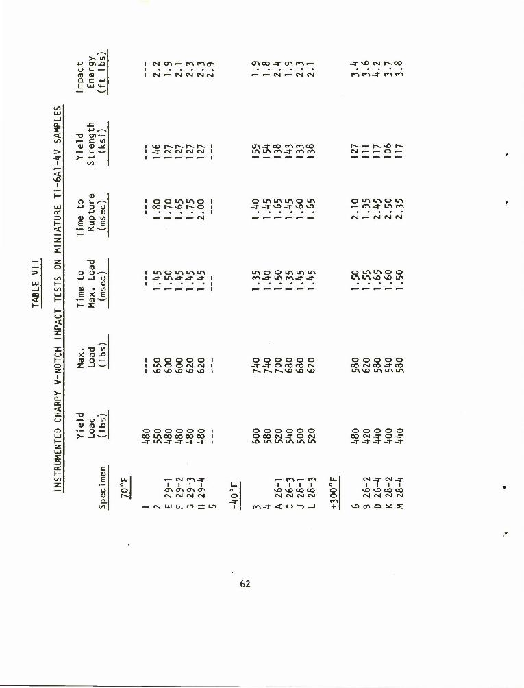
,_. >• in
i-> en -O o i- f— OJ 0) Q. C 4J b LU U_
I CM <J\ — CA CA<ri I i CM — CM CM CM CM
enco -3 <r> CA —
•— — CM •— CM CM
-3 MD CM r^co
CA CA-3 CA CA
CO LU _l Q_
< CO
> -3"
<
F <
a: <
13
CO
-D Dl — — C l/> a) a) _*
— i_ ~—
>- •M
0) o u*-% *-> D U
4J 0) t> a. <n
•— oc ^—*
I -3- CM CM CM CM I I _ _ _ _ _ |
ooiAino i
CXI -3" CO CA CACO LA LTV CO -3- en en
o uMntrtom _3- j- vD -3 MD vD
CM — — O —
O LA LO O LA — On .* LA m
CM — CM CM CM
— Z T5 _ o n > o o-— I
CO 4-1 —1 U I LU r- 0> I —I CO 4) • l/l m LU EXE < F .- ffl —- r- 1- X
H <-> <
-3" LA-3 -3" -3 LA O O LTV LA LA CA-3 LA CA-3 -3
O LA LA O O LA LAM3 \0 LA
• •n in X ID -O TO o «—
3L _I *—' I O O O O O I I LA O O CM CM I t vOvOvfivCvO I
O O O O O O -3" -3" O CO CO CM
o o o o o CO CM CO -3" CO LA vO LA LA LA
T3 —.
4) (0 -Q — O — >- -1 —
c 0) b LL. • — O o O a> r»- a.
CO
O O O O O O I CO IACO COCO CO I -3- LA-3- -3- -3 -3" I
— CM CA-3 I I I I
o-i en cri (Tv CM CM CM CM
— CM LU LL. O Z LA
o o o o o o OC0N3ON \0 LA LA LA LA LA
o O -3
I CA-3
1 CO ro
i Lc o
vO vO CO CO O CM CM CM CM O
ro < O -) _J +
o o o o o CO CM -3 O -3 -3- -3 -3 -3 -3
CM -3" CM -3- I I I I
vOvCOOCO CM CM CM CM
vOffiO^X
62

CD
0) c
e </> — -O
_J -C I U 4_i 4-1 U.
>
>- Q. L-
6 -
4 -
Bar Stock
Outer Web
Central Web
I sothermal
Forgings
100 -L
100 200
Temperature (°F)
300
Figure 30. Results of Instrumented Charpy V-Notch Impact Testing on Subscale Impact Specimens, Impact Energy vs Test Temperature.
63

h. The isothermal forging conditions of pressure at 10 tons per square Inch, temperature at 1650°F In the die cavity and dwell time of 10 to 12 minutes provide adequate metal movement to fill the die cavity with the current lubrication and preheating practice. These conditions result in no detectable creep deformation or cracking In the IN-100 die material and also provide for reproducible thermal expansion effects on part dimensions,
5. The importance of microstructure in the plate or bar stock utilized for isothermal forging preforms is recognized and documented. Microstructural requirements are well within the capa- bilities of titanium producers and should not add to the cost of material procurement.
The process specification for isothermal forging of titanium alloy weapon components resulting from this first phase work is provided as Appendix I to this report.
64

III. PROCESS DEMONSTRATION - M85 COVER PRODUCTION
As in the Phase I simulated component isothermal forging program, the Phase II efforts were planned in two successive forging sequences. The purpose of the first sequence was to establish a viable preform design for the M85 cover, while the purpose of the second was to manu- facture a quantity of covers sufficient to determine process feasibility and economics. In general, the process specification of Appendix I was followed in both iterations and the principles learned from the Phase I work provided important guidelines as described in the following report sections.
A. First Forging Sequence
1. Isothermal Forging Tooling
A set of cast-and-machined IN-100 tooling components consisting of a die ring and upper and lower punches was available for use on this program. This tooling had been employed previously in a program to produce M85 covers from steel powder(7). it was anticipated that these tooling components would not be completely satisfactory for use on this program for the following reasons:
1) The coefficient of thermal expansion of Ti-6A1-W is lower than that of k(>30 steel (5.7 x 10"° in/in/°F as opposed to approximately 8.1 x 10"° in/in/°F). Therefore forgings made from the titanium alloy on tooling designed for steel will be noticeably over- size in the dimensions of 1 inch and greater. This problem must be corrected by applying a negative shrink factor of 0.0051 in/in (based on an IN-100 expansion coefficient of 8.8 x 10~6 in/in/°F) in the tooling design. Thus the available tooling could not be expected to produce parts within the required dimensional specifications.
2) During execution of the previous program , the die ring had cracked at diagonally opposite corners of the roughly cruciform shaped cavity. The cracking and the associated distortion of the ring resulted in the need for some surface grinding of the cavity to prevent the punches from binding with the ring. The net result of this was the occurrence of relatively large clearances (0.020-0.050-inches wide) between the punches and the die ring with attendant difficulties in uniformly heating the punches and in production of heavy fins during forging. These provided no apparent difficulty to the powder forging program as evidenced by the fact that over 80 forgings were made after the cracking occurred.
(7) F.N. Lake, "Lubricant Development for Hot Die Forging of Small Blades," TRW Inc. Technical Memorandum No. *»712, December 1972
65

It was decided in the interest of program scheduling to perform the first iteration of isothermal forging with the original tooling. Since the purpose of this sequence was preform design, minor dimensional inaccuracies were not expected to be important. During execution of this sequence a new upper punch was designed to compensate for thermal contraction on the interior features and closely fitted to the existing die ring cavity on the lateral surfaces. Fabrication of the punch by surface grinding and electrical discharge machining took place between the two sequences.
The isothermal forging tooling was assembled in a 2500 ton Erie Foundry press in the TRW Equipment TAPCO manufacturing plant. An assembly drawing illustrating the die system and induction heating coils is supplied in Figure 31. Insulation of a type similar to that used by Abson et alj'^' but consisting of alternate layers of ceramic in- sulating cloth and Type 30*» stainless steel sheet was provided around the bottom surface of the ring die, above the upper punch and below the lower punch. A total of 10 Chromel-Alumel thermocouples were welded to the surface of the ring die at various positions around the outside but within 1/8 inch of the ring cavity. Several additional thermocouples monitored the temperature at the extreme outside of the ring and at various strategic positions within the system.
The progress of deformation was monitored with dial gages fixed to the press near each of the four posts. These measured the downward movement of the ram during the pressing sequence and thus allowed for reproducible starting conditions for all isothermal forgings.
2. Preform Design
The first step in the preform design process is determination of preform volumetric requirements since the total volume must be virtually identical in the preform and the finished forging. In addition, the distribution of volume in the preform must be simply related to the volume of the forged part; a substantial amount of longitudinal metal flow will not occur and therefore the volume must be placed at least approximately in its correct position with respect to the long part axis. Figure 32 illustrates a graph of cross sectional area of the forging as a function of distance along the length as determined from planimeter measurements on a series of twelve cross sections at various stations along the cover drawn at 2X size. This graph serves the purpose of identifying the critical volumetric relationships that must be fulfilled. The total area under the irregular plot numerically equals the total volume of the cover. A superimposed plot of a possible preform
(14) D. Abson, T. Brown, F. Gurney, "Heated Dies for Forging and Friction Studies on a Modified Hydraulic Forge Press," AFML- TR-72-255, Astronuclear Laboratory Westlnghouse Electric Corporation, November 1972.
66

Figure 31. Schematic of Isothermal Forging Die for Cover,
67

C o *-> o c 3
u_
(0
v> <o • VI u +J 0) c > a> o
' e o u u-\
— CO D X O-
0) 14- oc o
z. s I — l_ •— < — u
LAJ — 4) > fl> +J
O C C O 4> u. — o
o 4-> ct < id "(D UJ to c CC 1 —
s VI "O (A 3
CC O ** 1_ •— O Ol
o c -z. o> o < C _J 1-
•U O) o 10 c
«- o •M — in < D
— C — o — •—
4-1 e — «J <n »- O CTi Q- (0
o o
CN
en
(S3H3NI 3HVfrt)S) tf3bV 1VNOI133S SSOdO
68
cross-sectional area distribution is shown by the dashed line on the graph. It is clear that one of the most difficult tasks of the isothermal forging process will be to move several cubic inches of material from the wide thin web of the cover into the high cross rib portion at the wing.
Figure 33 illustrates a second diagram of major importance to the preform design process. This sketch shows a longitudinal section through the center of the lower punch of the forging tooling. Two preforms are shown superimposed on the die cross section. One, a flat plate preform, shown by the dashed 1 ine, contacts the die at two positions only and thus can cause excessively high unit loading along the two lines of contact. Also, since the upper punch does not exert a substantial bending effect on the preform (punch contact is first made at the ends), considerable difficulty with fill on the lower surface of the forging is anticipated with a flat plate preform. The preform shown by the dotted outline in Figure 33 is tapered so as to seat positively against the lower punch. Since this general shape concept offers numerous advantages from metal flow, tooling stresses and heat transfer considerations, it was chosen for use in the M85 cover forging process.
The Phase I forging results proved that timing is also important in isothermal forging. The basis for this concept is illus- trated schematically in Figure 3^, which shows two possible configurations during filling of a rib-web type forging. The upper illustration depicts the forging pressure distribution that could result from the use of a preform with a rectangular transverse cross section. The pressure distribution follows a typical "friction hill" type behavior with a pressure peak at the "neutral surface" or the surface at which metal flow divides. In other words, on either side of this neutral surface flow proceeds in a single direction. The pressure distribution sketched above the forging cross section illustrates the condition that must apply based on force equilibrium. Each branch of the friction hill represents a pressure that initiates at the base of the rib with a value determined by the back pressure exerted by the rib material. This back pressure is a function of the lubricant effectiveness, the surface area of frictional contact (degree of fill) and the material flow stress. The branches of the pressure distribution intersect at the neutral plane. The pressure distribution rises as the forging web thickness decreases and as the surface-to-volume ratio of the forging gets larger. Deformation stops when the average pressure determined by the distribu- tion reaches the applied forging pressure, as illustrated by the dashed line in Figure 3*». From this example it is seen that in order to achieve complete fill in difficult to fill areas, such as thin ribs or high projections as are typical of the M85 cover, it is necessary to prevent premature fill of the easily filled forging segments.
69

l/>
8. E
4) Q-
in
E
0)
•M
5 2
5
P
C O
a
en c o
70

BACK PRESSURE
FROM THIN RIB
FORGING PRESSURE
DISTRIBUTION
MAXIMUM PRESSURE SETTING
NEUTRAL PLANE
AVERAGE PRESSURE
7 BACK PRESSURE FROM THICK RIB
a. SITUATION EXISTING WHEN EASY-TO-FILL RIB FILLS EARLY IN PROCESS
Figure 3^. Schematic Illustration of Pressure Requirements in Isothermal Forging of Simulated Weapons Component.
71

FORGING PRESSURE
DISTRIBUTION
NEUTRAL PLANE
BACK PRESSURE FROM THIN RIB
MAXIMUM PRESSURE
AVERAGE PRESSURE
BACK PRESSURE FROM THICK RIB
b) SITUATION EXISTING WHEN EQUAL BACK PRESSURES ARE MAINTAINED BY CORRECT PREFORM DESIGN
Figure Ik. Continued
72

Preventing this premature fill condition can be accomplished by at least two techniques in isothermal forging. First, it can be accomplished with die design, by Increasing the height of easily filled ribs, the excess to be removed by machining^). Second, it can be accomplished with preform design by Increasing the distance material must move to fill the more easily filled segments. The second alter- native was proved feasible in Phase I of this program and has been utilized in preform design for the M85 cover.
The three preform design principles above, with the additional requirement of a minimum of 15% deformation, were utilized in the design of a series of preforms of the type illustrated in Figure 35. These preforms are basically rectangular flat plates cut to the general cruci- form shape of the cover. The longitudinal and transverse facets as seen in Figure 35 were machined on one flat side of the preforms. After precoat application and preheating, the side of the preform shown in the photograph is placed on the lower die for forging. The longitudinal facets thus serve the function of providing conformity to the lower die to minimize the possibility of excessive unit loading and also to prevent the formation of a lap or fold at the radius of the lower die depression (Figure 33). An important feature of these preforms is that they are of a configuration that would be easily forged from starting stock in the form of round or rectangular blanks. It is also conceivable that simple rectangular shapes, without facets, could be used in the isothermal finish forging operation, but attempts to accomplish this objective in the first set of forgings led to a lack-of-flll defect adjacent to the forged depressions in the center web of the cover.
3. Ti-6A1-^V Forging Stock
The microstructure of the material purchased for the iso- thermal forging of the covers is illustrated in Figure 3$. The titanium was supplied as 0.650-inch thick plate from Timet Heat G-1386, and was abrasive cut to the overall length and width of the extreme dimensions of the cover. The microstructure illustrated here is extremely fine- grained and uniform, and meets or exceeds the microstructural specifi- cation of Appendix I.
k. Isothermal Forging Results
Eleven cover forgings were produced in the die setup and preform design trial. The temperature, pressure, dwell time and preheat cycle conditions for these forgings are summarized in Table VIM. As anticipated, the forging pressure requirements and preheat cycles
(4) A.J. Vazquez and A.F. Hayes, "Isothermal Forging of Reliable Struc-
tural Forgings," AFML-TR-74-123, Ladish Company, June 197**.
73

Figure 35. Three T1-6AI-AV Isothermal Forging Preforms for the M85 Cover.
Ih

A*
Figure 36. Microstructure of Ti-6A1-^V Forging Plate Stock from Timet Heat Number G-1386
75

CO <
LU o z UJ
UJ </>
«/> e£ UJ > o <-> LA CO
o li-
en
o
o o 13
or o
<
o
— u. O o >» C o —
2:
-C "v. <v c u —
OOLAOOOLAO IA4NlAvOina\N lAlftiniAlAiniAvO
LTV O O N CO Ift vo 4 m
LA LA O 0 0 O •s. LA LA LA O O
O O
O O
1 O O
1 0 0
f
0 0
1 O O
O O
1 O O
1 O O
O O
1 O O
OA CO OA PA OA OA CA OA CA CM CA
0 LA 0 0 O O O LA O O O 1/1
TO >
^^ m .— <D _ 0) 4-1
a) F 3
l r- c 2:
0000 N 03 S N VO
^^ OJCM l_ c 3 — l/> ^% 1/1 c/) a) C i_ O a. H '—'
— — \o • * • r^ r- 00 o o
-a •— "O l/> — TO c o. o O Q-_i 1- < -—
0 O O O O O O O O O O LA LA O LA LA LA LA LA LA LA LA CM C-4 CA CA CA CA CA CA CA CA CA
L_ O O O O LA LA LA O LA O O 3 CO vD LA r^ CO P-- CM LA -3- O en 4-> *—_ LA LA LA LA LA LA ^O MD v£> LA LA TO U. t- 0 \ V ^-. \ •^ ^ ^ ^- ~^ •^ -v Q) ^ O LA O LA LA O LA O LA LA O a. CM .— O CM CA CM vO CA CO VO LA E LA LA LA LA LA LA LA LA LA -3" LA
E
-0 c TO E 3 " 1- >- .— 4-1
X • — F
> TO L)
a> -C Ol •M C
•—
4) l_ 1- TO CO
-O XI (D
•u a) u -C
a 4-J
CO <4~ b. O 1/1 >- CO 1- i~ Cl) 3 JZ
4-> Q- TO •— 1- V. CO CO CL Q.
01 c u ._ <u CJ) _Q »- E
.O 3
— cMcA-a-u-vvor^cocrio.—
§ <u
5 -o 4-> C
3 4) O
JC u I- TO •K
76

determined in Phase I proved adequate for the cover forging. The temperature attained by the punches was visibly lower than in the Phase I tooling, however, and this was attributed to the excessive ring-punch clearances described previously.
Figure 37 illustrates the set of eleven isothermally forged covers from this first iteration. The covers are arranged in order of their occurrence in the forging sequence starting at the upper left of the photograph. Several interesting features are apparent in this figure. Forgings number 1 and 2 were made from narrow rectangular preforms that were required to flow laterally to fill the wide web of the cover. The lack of fill adjacent to the depressions is evident in the photo. The first three forgings were produced at relatively low temperatures. A degree of underfill particularly severe in the high transverse rib and in the smaller pair of projections was exhibited. The underfill problem was more directly related to volume distribution than to temperature. That is, in forgings two and three complete fill was achieved at both ends early in the pressing cycle and this completion of fill was sufficient to prevent further deformation. The degree of detail reproduction and progress of deformation even at this low temper- ature was an unmistakable indication that the uniformly fine equiaxed microstructure of this forging stock is significantly better than that of the Phase I stock and thus is approaching the optimum for isothermal forg Ing.
Forging number k was the first to be produced with both longitudinal and transverse facets. These were found necessary to provide more stock at the longitudinal centerline and less at the edges. The degree of fill in this forging and subsequent ones was virtually complete. Some evidence of rounded corners and slight underfill is exhibited, but this was caused by an accumulation of lubricant on the cold corners of the punch impressions. This lubricant accumulation was a direct result of the low operating temperature of the punch caused by the excessive ring-punch clearances.
Forgings number 10 and 11, however, show a severe lack of fill. This was caused by the accidental loss of the thermocouple used to control the on-off sequence of the induction heating power supply. Loss of that thermocouple caused a power shutdown resulting in a cooling process that continued for about 2 hours before the failure was detected. The system was brought back to 1600°F as indicated by thermocouples on the ring die, but as is obvious from the conditions of forgings 10 and 11, the punch was substantially colder than the ring. It was decided at this point, in view of the fact that several thermo- couples had broken away from their welded positions, and also in view of the success achieved with forgings *» through 9 that the forging sequence had proceeded far enough and the die system was allowed to cool slowly under controlled conditions to ambient.
77

Figure 37. First Iteration M85 Cover Isothermal Forgings
78

Several of the forgings in Figure 36 show a heavy fin extending normal to the web around the perimeter of the forged covers. On other forgings the flash has been trimmed away to allow measurement of web thickness dimensions. This flash actually provided some benefit in the preform design development as it vividly pointed out those cross sections where volume was excessive. It did add somewhat to the diffi- culty of filling the high ribs and projections and its removal was troublesome. In the second iteration, the punch was fitted tightly to the ring die cavity and the excessive flash condition was alleviated.
The forgings were lightly sandblasted after forced air cooling to remove residual lubricant precoat and then were inspected visually for any defects and dimensionally to ascertain the effects of thermal expansion on the finished forging tolerances. The results of this dimensional inspection were incorporated into the design of the new upper punch.
B. Second Forging Sequence
1. Tooling and Assembly Modifications
The die system assembly is illustrated schematically in Figure 31. Several revisions were made in the materials and hardware of this assembly based on the results of the first forging sequence. For example, the thermocouples that control and monitor the temperature distribution in the die system were placed in thin-walled Inconel pro- tection tubes welded to the ring die in place of the previous practice in which these thermocouples were attached directly to the die. In the last iteration, as previously reported, weld failures at these control thermocouples resulted on a few occasions in unexpected power shut- downs which lead to time delays spent waiting for the system to recover the lost heat. Inserting thermocouples into short lengths of swaged tubing reduced the probability of this event recurring, and also.made it possible to replace a defective thermocouple without cooling the system to room temperature for rewelding.
The laminated insulation below the die ring and at the base of upper and lower punches was increased with several additional layers of stainless steel and ceramic sheet insulation. Below the die ring the stainless steel sheets were extended to conform more closely to the lower punch so as to act as shields to prevent heat loss by radiation to the cold tooling in the ejector mechanism.
79
The major change in the tooling system was the adoption of a new punch revised according to measurements made on the first iteration of cover forgings to account for effects of thermal contraction. The tooling drawings for this new punch are illustrated in Figures 38 and 39. Two separate engineering drawings were made, the first in Figure 38 illustrating the lateral dimensions of the punch as ground on the IN-100 casting and the second, Figure 39, showing the interior details of the working punch face. The grinding dimensions represent the distorted contour of the die ring as determined from an inspection of the ring on a coordinate measuring machine (Boice Co., Acra-Cord). This inspection revealed that the die had distorted into the shape of a parallelogram rather than a rectangle because of the formation of cracks at opposite corners of a diagonal. The side and end walls were made parallel by enlarging the cavity, and thus the forgings are slightly wider and longer than specified in overall dimensions. Some additional machining would be required on these forgings to bring the widths and length within toler- ances. In grinding the punch lateral faces, account has been taken of this situation and the working punch details are located symmetrically with respect to the M85 cover longitudinal and transverse datum planes.
2. Preform Manufacture
Consideration was given to alternative methods of manufacturing preforms for isothermal forging. The preform, designed according to the principles described earlier, is illustrated in Figures hO and k\. The prints shown in these figures were reviewed with machining and forging specialists in evaluation of alternate techniques together with their costs and lead times.
Two types of forging equipment were considered for making these preforms, a mechanical press and a steam drop hammer. Since the preform as selected had the cruciform shape illustrated in Figure ^0, a set of forging dies is required for either type of equ ipment.
Mechanical press forging was discussed with personnel of TRWs Tapco manufacturing facility. It was concluded from this discussion that while crank press methods would be readily adaptable to manufacture of the preforms, amortization of die development costs and the long delay required for die machining made their use impractical within the cost and schedule framework of this program. Hammer forging was considered as an alternative technique since many shops are equipped with steam drop hammers of the size needed for these preforms. These shops are accustomed to forging parts in small
80

•r,^^'"^^^"^^"*"^r"^^T"
i !!
!•
pa —••». _ v ( »:
*3
a l<
_ ~> 1 r n Q
& M
FR
C-S
UDVj
J3
^
\
I f 1
1_ _ r~ !
i— r
J3
S
f I
!
jjl
Mi I iiilf
91 c •— -o .— c
8 o i- u
<J m i_ <u •— o en 0) L U- O i_
U- 3 t/5 «_
OJ in & (TJ i_ <u i/i x: c •n O
s in — c 0)
<4- F n
Q 4-> c ,— 4) m C i_
a 4) 4-J
§ 05 _l
CJ en
-C c o •— c •M 3 <T>
D- 1_ 4-J
V. l/l 0) 3 O. Q. ,—
=) —
oo
o> 1- 3 CD
81

Ol >- c XI
,_ T> o 1) n c
H- •— x:
cn a c <TJ •— X Ol L. Ul
O T3 U_
Ul ,— C ro o t- i_ Ul 0) c
x: a> •M F Si Q
0 H- u O (0
la. 4-> c m 0J c c •— a E o O 3-
<-> m
X. c o •— c J-> 3 aj
Q. i_ 4-1
1_ Ul <U 3 Q. ,_- a. 1—
ZD —
• en f-i
0) L. 3 a:
82
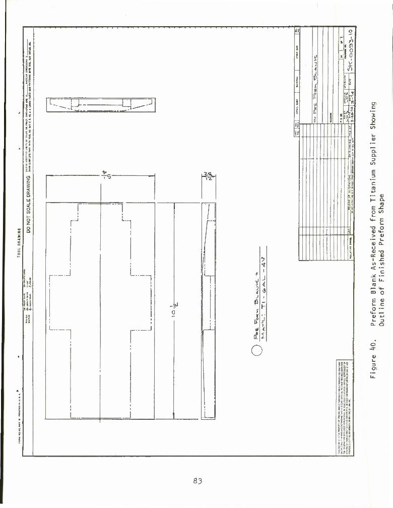
I I ! I I I I
u u II
it - 4
if:
Ill g
< Q UJ
< o
s
111
I H-|4<
L ! J 1 J •-•>H y^-
^5 IX"
r i
"1 'I r"
t
1
[i i
i I
V
1
< 1
L_n rJ
1_
* •*
t '
* 3* J 1
P r f- i
i'i Y Ml 4
ft 2
o
i?
««
< <n I ° I?
Y 7i
e?
*
Hi* 8§Ss Igfi |S§5
Hi! il i l||ai
III tills ill!
83

a _ L i iO
J i ;l? u y it 10
1 i
li H
0 0 J li
L-4: ^ i 1 (1 5? 'A f i
V 0
* z !M N h r • a i? i
M 1 2
fi
«!y OOS>
-J3 ns
OOS'l i O rii Z li I B 1
o< Sl'Z
m o'-
< 3-
8 i S
— i f ? 1 l
ri t i i
5
1 4 \ /
-1 t •
> i <! \ / 0 < r
I |4*
\ \ r-
/:
J ( 1
0 0 i(
**-*• * V .0 •
j li . i •.1 1
0 r in fi
1 L 8! ( "1 1 M U
0
8 n i
Mil
ills
N 1
|i*s gill l|ih >|isj 5§i:t *5=I* S5?3E
ifii III *"H OOS'2
liil*
84

quantities on a job shop basis. This method, whi 1 e attractive from the program standpoint, proved impractical from a time and cost basis. In particular, a die charge of $10,000 was required to start production of the preforms. This die charge included all dies needed for manufacture of the part as long as production was continued. A second limiting feature of the hammer forging source was the minimum of 16 week delivery schedules, governed primarily by die material lead time and die block machining time.
Both forging suppliers expressed confidence that no manufacturing difficulties would be encountered with preform forging and that the quality and tolerance requirements were well within their usual capabilities. The problem of maintaining or producing a micro- structure optimized with respect to isothermal forging behavior was discussed, and it was decided that conventional forging techniques offer considerable flexibility in this regard through control of forging temperature and degree of hot working.
A few alternate machining methods, including grinding, shaping and milling, were also considered with the result that costs were lower and delivery time was considerably shorter (5 weeks) with parts machined by milling for the number of preforms required for this final iteration (seventy-five). Therefore, after some discussion with Rock Island Arsenal personnel, it was decided that machined preforms would be utilized in order to remain within the program funding and time restrictions.
3. Ti-6Al-*tV Forging Stock
Forging stock was received from the warehouse supplier after considerable delay attributed to order backlogs. The material was inspected and characterized metallographical1y and transferred to the machine shop for preform machining. Table IX lists the chemical analysis and mechanical property data for this material.
The material was noted to be unresponsive to one of the conditions of the purchase requisition in that the heat code designated (Timet G-1386) was not shipped. Rather, the material re- ceived was from Reactive Metals heat code 30A209. The microstructure of the RMI material shown in Figure k2 can be compared with the Timet stock from Figure 36. The RMI material does conform generally to the conditions of the microstructural specification in having a structure indicative of processing within the alpha-beta temperature range. The
85

to LU
LU CL. O
a.
< t_> ^ — o z o < K l to <_> LU CJ
z cc < o
9 to >- < < Z vO
< — O
t_>
Q
LU
Si
5 tf
C CM o **?
-C <u 4->
•— Ol •— c i/> 0) c i_ 0) •M
h- CO
s: *->
"O Oi 1— c 0) <D •— L.
>- 4-1 to
o
CM
o o LA
n
CO
O o o en CM
o
o
o o o
m o CA
o o o
H o CM
c
o
H cS
CM O •
o
CM X
oo o o
• o
> co
• -a-
< -a- CM • SO
LA
CM Z
O • O
0) li.
LA O • o
(_> vO O O
<u
o CM
1 • O
LA ^— 1 o •
o
o o LA LA • • m -3"
o LA LA r-~ LA vO
LA O
O CA
OO o
c 0Q 0)
= 1 en CT\ U o -3- — ^3- 3
— CM to cr x: o X <D a: PA < oc
X
86
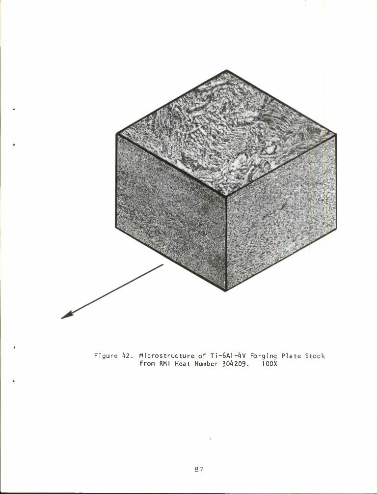
Figure k2. Microstructure of TT-6A1 -AV Forging Plate Stock from RMI Heat Number 304209. 100X
87

Timet material utilized in the first iteration of M85 cover forgings is finer, however, in the normal direction. Since the RMI material satisfied the compositional and physical requirements of AMS 1»911B» and because of the critical nature of program scheduling, the lot of material was accepted.
k. Finish Machining of Cover Forgings
Appendix II lists a tentative routing for finish machining the M85 covers to be used for completion of the isothermal forging program. This routing includes a total of kO individual machining operations primarily involving drilling, reaming and counter- sinking holes and making undercuts. Some operations involve machining flat surfaces but in most cases these are concerned with removing draft from the sides and ends of a few surfaces. Machining the 2°, 6° and flat surfaces on the top of the cover is primarily cosmetic. Operations 35 and kO are concerned with machining the outer periphery of the covers and, as has been described previously, are needed for the present program only because of the enlarged configuration of the die ring. Machining the zero draft outer walls will normally not be required in isothermal forging. Flash removal in operation 5 involves a minor amount of hand burring or snag grinding. The flash will be present only as a very thin (0.020-inch thickness) fin around a portion of the outer wall of the covers.
Some hand straightening will usually be required because of the ease with which bending can occur at the edge of the wing that adjoins the hinge pin end of the M85 cover. This junction is a point of weakness in the cover and can become bent on removal from the iso- thermal forging tooling or simply by residual stress on cooling from the forging temperature.
It is to be noted that the machining operations included in this preliminary routing are not nearly as extensive as those required for rough and finish machining of hammer forgings as presently performed. The operations themselves appear to be readily adaptable to numerical control machining techniques.
5. Isothermal Forging Results
A total of ten isothermally forged covers were produced in the second iteration before the sequence was prematurely terminated by a catastrophic fracture of the die ring. The program time limitations, remaining funds and the developmental nature of the program precluded the option of manufacturing a new ring and repairing the tooling to allow
88

continuation. Therefore, the number of forgings produced was considered sufficient. The program was considered complete and remaining funds were directed toward redesign and construction of tooling for further research into production of covers from steel powder.
Even though they were limited, the results of the second sequence of isothermal forgings were encouraging. The last several pieces showed a good degree of fill without evidence of lubricant en- trapment. The details of the upper punch were reproduced well by the titanium alloy. Figure k"} illustrates detailed views of one forging from the sequence. The sharp radii, good fill and uniformly fine surface finish are worthy of note. Some forging defects are apparent on the part, but these are not considered a serious limitation to the process. Work had been accomplished toward eliminating these defects when the failure occurred. A discontinuity in the outer side of the rib on the hinge pin part of the cover occurred on one forging only and appeared to be a piece of foreign material such as possibly a thin broken fin. This should not interfere with the cover in this instance because the defect appears thin enough to be machined away when the outer sidewalls are milled to size during finish machining. A potentially more serious defect appears on the upper surface of the cover adjacent to the hinge pin end. The defect occurred because the top surface fill was completed at the hinge pin end and midway up the 6° sloped wall essentially simultaneously. Several alternatives are available for eliminating this defect. The simplest is preform modification by the removal of some stock from the hinge pin end to delay fill at this position. This alternative was being investigated at the time failure occurred. One or two other shallow blemishes were apparent, but these were on surfaces to be machined subsequently, and therefore their presence is acceptable for the purpose of this program. In production, these could readily be eliminated also by preform modification or die design allowances.
Temperatures, pressures and dwell times lower than those in the original process specification were followed for the first five pieces. These were considered set-up pieces and were utilized to ascertain the material and die system behavior since some minor changes had been made both in the tooling assembly and in the material microstructure. Following pieces were pressed with a die ring cavity temperature ranging from 1600°F to 1650°F and with an applied load of 375 tons (10.7 tons/in2). This minor increase in temperature and pressure conditions was necessary to attain the degree of fill shown in Figure **3 and possibly was required to overcome the effect of the change in alloy microstructure. The initial
89

a. Hinge Pin End.
b. Breech End,
Figure *»3. Details of Forging 9 in Second Sequence Isothermal Forging.
90

production rate for these pieces was about 1 piece per hour and was limited by the time required for the punches to regain the heat lost to the surroundings during forging (when the laminated insulation is under pressure and thus is least effective). Optical pyrometer readings on the upper punch near the die ring provided the signal to resume forging. When the punch temperature reached 1600°F the forging sequence was initiated.
A photograph of the sequence of ten forgings is provided in Figure kk. The forgings are shown before removal of residual forging lubricant, except for forging 9 which has been sandblasted and trimmed of excess forging fins. The ninth piece is considered to be representative of covers capable of being produced by isothermal forging. The temper- ature and pressure conditions for numbers eight and nine were identical at 1650°F and 10.7 tons/in^, the only difference being an extended dwell time of 15 minutes for number 9.
The damaged forging (number 10) exhibits a melted corner at the hinge pin end. The cause for this arose from formation of a massive crack through the die ring after six minutes of pressure appli- cation. The induction heating power was on when the failure occurred, and the crack interrupted the current path through the IN-100 ring. This caused formation of a short circuit path through the titanium alloy with the resulting high current density supplying the heat required to melt the corner of the forging as shown.
The trap die concept is a practical means for producing isothermally forged weapon components. The outstanding advantages over more conventional flash line parted designs include: 1) ejection over the entire plan area of the forging, thus minimizing distortion; 2) economy of material since flash losses are minimal; and 3) relatively low press bed space requirements because the design permits the use of compact support tooling. The failure in the die ring must be attributed to thermal stress conditions. This is evidenced by the fact that the cracks formed initially before any forging had been performed. The crack growth rate was initially quite slow, but once a critical crack opening was exceeded propagation to failure was immediate. The possi- bil ity of a recurrence can be minimized in future designs through careful attention to the effects of thermal gradients and the action of stress concentration in this type of forging tooling.
91

o (D
4- l-
co
E O *-> *->
&
o in
Q
g
CO
o
OJ
L. 4)
O
LA oo
-3- -3"
<U L.
cn
92

C. Process Economics
The production of titanium alloy M85 covers by isothermal forging is fundamentally different from production of low alloy steel covers by hammer forging and machining. A legitimate comparison of costs for these processes must include the expenses associated with raw materials, tooling, capital equipment, energy, expendable supplies, post forging treatment, heat treatment, and rough and finish machining. Several of these expenses are directly comparable, but others depend on factors not easily assessed, such as equipment availability, amortization schedules, company established crew size regulations, amount of in-process inspection, and production lot sizes. The cost data presented in this report section are mainly direct comparisons based on fixed charges and standard hour estimates. Additional data were provided in the report text to allow more exact analysis with account taken of those factors characteristic of the specific manu- facturing facility. Two situations are discussed; in the first (called Process A) costs are estimated based on the methods and prices of the current program; and in the second (called Process B) a projection is made based on process improvements suggested but not necessarily proven by the current effort.
The standard hour and fixed cost estimates for conventional production and the two isothermal forging processes are compared in Table X.
In Process A, it was assumed that one man operates two hot die systems simultaneously, thus producing a forging on one system as the other recovers the heat lost during the previous operation. An arbitrary rate of $25 per hour has been assumed throughout for the cost comparison. No allowance has been made for differences in machining practices between the titanium alloy and low alloy steel since Ti-6Al-AV is regarded as a readily machinable material. Tool wear is expected to be somewhat increased with titanium, however.
Process B lists the estimated standard costs for an isothermal forging technique that realizes a lower cost through elimination of expenses associated with preform preparation. The preform for this alternate process is a simple one, being approximately 10-inches long by 3-inches wide with longitudinal angular relief provided to fulfill volumetric requirements and to allow positive seating with the lower punch. The construction of the lower punch is modified in that the step and 6° angular rise to the hinge pin end are not present. The lower surface of the forged cover is flat, the excess stock to be
93

TABLE X
PROCESS ECONOMICS - M85 COVER
CONVENTIONAL PROCESS
Standard Set-up Operation Hrs/Pc $/Pc Hours
Raw Material - 4.50
Heat, Forge 6 Trim 0.0735 1.84 5.0
Cold Finish Form 0.0735 1.84 5.0
Normalize 0.2400 6.00 - . „, ... 0.04 hrs/lb
Harden 6 Temper 0.2400 6.00 - X 6*° ]bs
Sandblast 0.0300 0.75
Machine 6.2051 155.13 156.7
6.8621 176.06 166.7
Total Cost Per Piece in 3000 Piece Production Lot $177.45
94

TABLE X (CONT'D)
PROCESS ECONOMICS - M85 COVER
ISOTHERMAL FORGING OF TITANIUM ALLOY
Operation
Raw Material
Preform Preparation
Forge
Post Forge Treatment
Stress Rel ief
Machine
PROCESS A
Standard Set-up Hrs/Pc $/Pc Hours
~ M.31 — $7.73/pound sheared and surface ground
- 52.50 - Machined
0.50 12.50 2*».0
0.10 2.50 *.o
0.10 2.50 - 0.04 hrs/lb x 2.6 lb
3M 86.25 95.0
200.56 123.0
Unit Cost in 3000 Piece Production Lot $201.58
95

TABLE X (CONT'D)
PROCESS ECONOMICS - M85 COVER
ISOTHERMAL FORGING OF TITANIUM ALLOY
PROCESS B
Standard Set-up OperatIon Hrs/Pc $/Pc
24.12
Hours
Raw Mater ial —
Preform Preparation 0.75 18.75 5.0
Forge 0.25 6.25 24.0
Post Forge Treatment 0.10 2.50 k.o
Stress Relief 0.10 2.50
Machi ne 3.75 93.75 95.0
147.87 128.0
Unit Cost in 3000 Piece Production Lot $148.9**
96

machined away as a final milling operation. The essentially flat surface thus provides a reference surface to simplify fixturing and inspecting. The upper punch design is unchanged except that the two elongated pro- jections that form grooves at the wing extremities would be deleted, the grooves to be added by subsequent machining. The simpler preform approach thus leads to added machining requirements, but the added costs are more than compensated by material savings and reduced preform preparation expense.
Recent developments in isothermal forging practice have demonstrated the practicability of a procedure regarding preheating that is different from that utilized in this program. The practice involves heating the preform to a temperature on the order of 1750°F, inserting the piece in the die cavity and pressing immediately at a rate substantially greater than employed in this program. The process is no longer a creep forming one nor is it strictly isothermal. The success of this method is contingent on the development of a lubrication system capable of providing long term stability at 1750°F while re- taining the anti-gal 1 ing, anti-friction, and low accumulation features of current generation lubricants. The anticipated success of the high preheat temperature approach has been incorporated into the cost model for the advanced process and the production rates have been increased accordingly.
The question of die life is a difficult one to address based on the results of this program. However, there is sufficient evidence available for IN-100 tooling in TRW and other programs to project a 1 ife on the order of 3000 pieces before the punches, par- ticularly the heavily detailed upper punch need redressing.
97

IV. CONCLUSIONS AND RECOMMENDATIONS ______________________ (
This program has resulted in definition and evaluation of a process for fabricating M85 covers from the titanium alloy Ti-6A1-*4V by isothermal forging. Major conclusions and recommendations resulting from this work are given below.
1. Optimum process parameters for isothermal forging of Ti-6A1-^V parts such as the M85 cover involve a forging pressure of 10 tons/sq inch (20,000 psi) at a die temperature of 1650°F with a dwell time of 10-12 minutes. Such conditions provide minimal risk of die distortion through creep deformation under applied pressure.
Isothermal forging tooling must be designed to avoid the damaging effects of stresses arising from thermal gradients.
2. Effective lubrication plays a major role in the cost effectiveness of isothermal forging. A TRW developed lubricant system performed satisfactorily during this program in providing low friction, negligible accumulation, easy release and minimal oxidation or interstitial pickup. This vitreous-binder, particulate-fi1 led lubricant system is limited to the low temperature preheat
cycle used in the program and is less effective at die temperatures just below those used in this program. Such limitations are not severe ones in a wel1 controlled process.
In future isothermal forging efforts, regardless of component or material system, whether it be titanium, aluminum or ferrous alloy in wrought or powder form, considerable attention should be directed to optimizing lubricant properties and maintaining lubricant standards through quality control in formulation and precision in application.
3. Preform design is of extreme importance in isothermal forging. Significant differences from conventional forging and powder metal practice are indicated. Three factors are vital. These include: 1) volume dis- tribution, 2) initial contact zones, and 3) fill timing. These must be optimized in a preform of very simple geometry to satisfy process economic constraints.
The preform design principles described in this report can be adapted to a computer modelling approach. Such "computer-aided-design" techniques will provide an important cost savings by eliminating preform development and by determining process economics in advance of costly manufacturing trials.
98

k. The M85 cover can be produced from a titanium alloy by isother- mal forging at a cost marginally higher than the similar steel part, and the titanium alloy forgings can meet cover specifications. With a further optimized balance between forging to net dimensions and finish machining to reduce preform expense, it has been estimated that a cost savings of ]S% is possible.
If isothermal forging can work for titanium alloys it can also work for aluminum, powder steel and other systems. Further work toward realizing this cost advantage should be considered and directed toward the wide variety of weapon components and alloy systems employed in modern weaponry.
99

V. REFERENCES
1. H.R. Nichols, W.H. Graft, V. Pulsifer, and P.R. Gouwens, "Development of High Temperature Die Materials," AMC TR-59" 7-579, Armour Research Foundation, October 1959.
2. T. Watmough, K.M. Kulkarni, N.M. Parikh, "Isothermal Forging of Titanium Alloys Using Large, Precision Cast Dies," AFML TR-70-161, NT Research Institute, July 1970.
3. K.M. Kulkarni, T. Watmough, D. Stawarz, N. Parikh, "Isothermal Forging of Titanium Alloy Bulkheads," AFML-7^-138, I IT Research Institute, August 197^.
k. A.J. Vazquez and A.F. Hayes, "Isothermal Forging of Reliable Structural Forgings," AFML-TR-7^-123, Ladish Company, June 197**.
5. C.C. Chen, W.H. Couts, C.P. Gure, S.C. Jain, "Advanced Isothermal Forging, Lubrication, and Tooling Process," IR-1 28-'* (1), Wyman- Gordon Company, July 197^.
6. F.N. Lake, "Isothermal Hot Die Creep Forging of Small Titanium Alloy Compressor Blades," TRW Inc. Technical Memorandum No. ^6^7, December 1971.
7. F.N. Lake, "Lubricant Development for Hot Die Forging of Small Blades," TRW Inc. Technical Memorandum No. ^712, December 1972.
8. Machine Gun, Caliber 50, M85, Department of the Army Technical Manual TM 9-1005-231-25, September 1968.
9. F.T. Lally, I.J. Toth, "Isothermal Forging of Precision Metal Powder Components," Summary Technical Report, Contract DAAF01- 72-C-0502, TRW Inc. July 1973.
10. Titanium Metals Corporation of America, "Properties of Ti-6Al-AV," Titanium Engineering Bulletin Number 1, February 1965.
11. D.J. Maykuth, D.J. et. al., "Ti-6A1-W Handbook," Defense Metals Information Center, Battelle Memorial Institute, AFML Contract F33615-71-C-l067, February 1971.
12. Testing and data analysis performed under the direction of Mr. F. Anderson, Rock Island Arsenal. Reported by personal communication, February 197^.
100

V. REFERENCES (CONT'D)
13. Battelle Memorial Institute Compilation of Available Information on Ti-6A1-V Alloy. Titanium Metallurgical Laboratory, Battelle, February 28, 1958.
\k. D. Abson, T. Brown, F. Gurney, "Heated Dies for Forging and Friction Studies on a Modified Hydraulic Forge Press," AFML- TR-72-255. Astronuclear Laboratory,Westinghouse Electric Corporation, November 1972.
101

APPENDIX I
Preliminary Process Specification
Scope
This process specification describes the material, equipment and processing requirements for manufacture of M85 machine gun covers (U.S. Army Part Number 7793151) from Ti-6A1-4V alloy by an isothermal forging process. The specification is preliminary as it is based on a development program under contract DAAF03-73-C-O093, and may require revision pending the results of further experience concerning pro- cessing parameters for the full scale part.
Applicable Documents and Drawings
1. TRW Drawing 8851-250-1, rev. 1, and 8851-250-2, Forging Tooling
2. TRW Drawing 8851-250-3, Cover Forging
3. U.S. Army Drawing No. 7793151, Finish Machined M85 Cover
k. Interim and Final Reports on Contract DAAF03-73-C-0093
Materials and Equipment
1. Isothermal Forging Alloy - The Ti-6A1-4V material for isothermal forging shall meet with the chemical and mechanical property requirements of specification AMS *»91 1 B or *»928 G with an additional requirement on microstructure as follows: "The microstructure will consist of equiaxed or moderately elongated alpha phase in a matrix of transformed beta in- dicative of finishing operations carried out below the beta transus." The predominant direction of working (e.g., the rol1 ing direction) shall be in the direction of the major dimension of the M85 cover.
2. Forging Tooling - Tooling shall be a closed die vertical action type with suitable means for ejecting the forging from the die cavity and freely retracting the upper punch. The tooling shall be produced from a high quality die material capable of operating in a temperature range of up to 2000°F with working surfaces maintained at approximately 16508F. Where thermal
102

stresses are potentially high, applicable radiographic inspec- tion procedures and standards (e.g., ASTM-E186, Class I I I at 2$ sensitivity) should be utilized to insure freedom from detrimental casting defects. The punch and die cavity dimen- sions shall be such that after forging the configuration shown in TRW Drawing 8851-250-3 will be achieved either directly or with not more than 0.025-inch of stock removal from external surfaces.
3. Forging Press - A vertical hydraulic forging press is required. This press shall have a minimum forging load capacity capable of providing a forging pressure of 10 tons/in^ uniformly over the plan area of the M85 cover forging. The press shall be equipped with an auxiliary ram for ejecting the forging from the die cavity.
h. Die Heating Facility - A means for heating the die enclosure to a temperature of approximately 1650°F and controlling this tem- perature accurately must be provided. This heating system can be of the induction, resistance or radiant heating type but must apply the heat in a uniform, well controlled and predict- able manner. The die system shall be suitably adaptable for control instruments to monitor die temperature during die heatup, idling and pressing cycles.
Requi rements
1. Preform Preparation - Preforms shall be coated on all surfaces with a 0.003-0.005-inch thick layer of an isothermal forging precoat of a formulation designed to provide good lubricating quality, protection from atmospheric contamination and re- sistance to galling during pressing. This precoat may be applied by any suitable means including dip, spray, or brush methods.
2. Preform Heating - Forging preforms shall be preheated to a temperature of 1300°F for a period of time sufficient to drive off all volatile components of the precoat. The second stage of the preform preheat cycle shall be a dwell within the forg- ing die cavity at 1650°F without load application for a time interval sufficient to insure thermal equi1ibrium within the preform.
103

3. Forging - The forging load shall be applied to the preheated preform for a time interval sufficient to produce the shape depicted in TRW Drawing 8851-250-3. Devices to monitor ram movement can be employed to determine the rate of deformation during the forging operation, and the cycle can be halted when the ram advance rate falls below 0.00^-inches per minute.
4. Post Forging Handling - Following completion of the pressing cycle, the part shall be removed from the die system by the ejector mechanism. Tongs or other handling devices shall be utilized for subsequent handling in a manner that minimizes the possibility of part distortion.
5. Heat Treatment - All forgings shall be stress relieved by heat- ing in air or in protective atmosphere for one hour at 1300°F. Residual forging lubricant need not be removed from the pieces before heat treatment as this can provide protection from atmospheric contamination.
6. Post Forging Surface Treatment - Residual precoat shall be re- moved from all forgings either by grit blasting or by chemical treatments with precautions taken with the latter method to avoid conditions potentially leading to hydrogen embrittlement.
10A

APPENDIX II
Tentative Machining Routing - M85 Cover U.S. Army Part Number 7793151"
Operation Description*
5 Remove flash.
10 Hand straighten.
15 Stress relieve.
20 Finish mill top surfaces (2°, 6° and flat).
25 Finish mill 2.17^0.003 dimension, hinge end shoulder.
30 Drill, countersink and ream 0.250+0.002 hole.
35 Finish mill left side holding 3-00-0.02 dimension to 3.000+0.010. Finish mill the 2.75-0.010 holding the 3.04+0.02 to 3.039+0.004 from loc. hole.
Deburr.
40 Finish mill right side holding 3.00-0.02 dimension to 3.000-0.007. Finish mill the 2.750-0.010 leading edges of wing and side surfaces to be in line within 0.002 with previous operation.
Deburr.
45 Mill draft from 0.312+0.005 slot holding depth to 0.564- 0.010, located 3.175-0.010 from hinge hole.
50 Drill and ream (2 sides) the 0.312±0.002 hole at 6-943± 0.001 from hinge end. Drill two 0.234±0.010 holes to depth of 0.269-0.008 from top surface, located at 3-327±0.003 from hinge hole.
"Dimensions in inches.
105
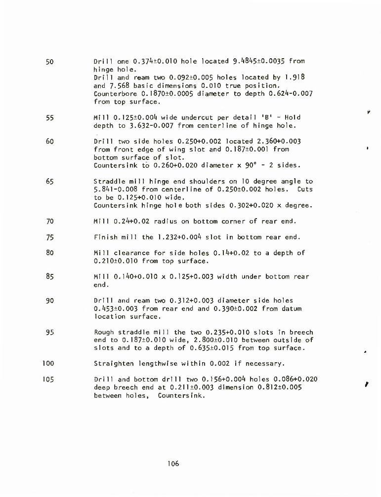
50 Drill one 0.37^0.010 hole located 9.A845±0.0035 from hinge hole. Drill and ream two 0.092±0.005 holes located by 1.918 and 7-568 basic dimensions 0.010 true position. Counterbore 0.l870±0.0005 diameter to depth 0.624-0.007 from top surface.
55 Mill 0.125±0.00l» wide undercut per detail 'B' - Hold depth to 3-632-0.007 from centerline of hinge hole.
60 Drill two side holes 0.250+0.002 located 2.360+0.003 from front edge of wing slot and 0.187±0.001 from bottom surface of slot. Countersink to 0.260+0.020 diameter x 90° - 2 sides.
65 Straddle mill hinge end shoulders on 10 degree angle to 5.8^1-0.008 from centerline of 0.250±0.002 holes. Cuts to be 0.125+0.010 wide. Countersink hinge hole both sides 0.302+0.020 x degree.
70 Mill 0.24+0.02 radius on bottom corner of rear end.
75 Finish mill the 1.232+0.004 slot in bottom rear end.
80 Mill clearance for side holes 0.14+0.02 to a depth of 0.210±0.010 from top surface.
85 Mill 0.140+0.010 x 0.125+0.003 width under bottom rear end.
90 Drill and ream two 0.312+0.003 diameter side holes 0.453±0.003 from rear end and 0.390±0.002 from datum location surface.
95 Rough straddle mill the two 0.235+0.010 slots in breech end to 0.187±0.010 wide, 2.800±0.010 between outside of slots and to a depth of 0.635±0.015 from top surface.
100 Straighten lengthwise within 0.002 if necessary.
105 Drill and bottom drill two 0.156+0.004 holes 0.086+0.020 deep breech end at 0.211+0.003 dimension O.8l2±0.0O5 between holes, Countersink.
106

110 Finish mill undercut per detail 'B' 0.125+0.00^ wide 0.130+0.010 deep.
115 Drill ream and counterbore two 0.186+0.003 diameter holes in forward walls of "wings" at 1.937±0.003 from each side of centerline and 0.652±0.003 from bottom surface and wing slot.
120 Drill and ream two 0.250+0.003 diameter holes in each side 0.222+0.002 from bottom surface of central relief. Spotface both outside surfaces 0.A27+0.020 diameter x 0.000+0.005 deep.
125 Mill 0.015+0.020 x k5 degree chamfer on bottom surface of large slot in wing (Detail B).
130 Mill 0.015+0.020 x 1*5 degree chamfer real end bottom surface 'T' slot (Detail A).
135 Mill 0.015+0.020 x kS degree chamfer bottom surface hinge end (DetaiIB).
]k0 Mill four Ik degree grooves in hinge end radius (Detail D).
1A5 Break all sharp edges 0.003+0.012 as required.
107

DISTRIBUTION
Copies
A. Department of Defense
Defense Documentation Center ATTN: TIPDR Cameron Station Alexandria, VA 2231^ 12
B. Department of the Army
Commander U. S. Army Materiel Development and Readiness Command ATTN: DRCRD-E 1
DRCRP-I 1 DRCQA-E 1
5001 Eisenhower Avenue Alexandria, VA 22333
Commander U. S. Army Materiel Development and Readiness Command Scientific and Technical Information Team - Europe ATTN: DRXST-STL Dr. Richard B. Griffin APO New York 09710 1
Commander U. S. Army Armament Command ATTN: DRSAR-PPI-K 1
DRSAR-PPI-WW 1 DRSAR-RDP 1 DRSAR-SC 1 DRSAR-QAE 1
Rock Island, IL 61201
Director U. S. Army Materials and Mechanics Research Center ATTN: DRXMR-M Watertown, MA 02172 1
Director U. S. Army Maintenance Management Center ATTN: DRXMD-A Lexington, KY 1»0507 1
108

DISTRIBUTION
Copies
Commander U. S. Army Electronics Command ATTN: DRSEL-PP/I/IM Fort Monmouth, NJ 07703 1
Commander U. S. Army Missile Command ATTN: DRSMl-IIE 1
DRSMI-PRT 1 Redstone Arsenal, AL 35809
Commander U. S. Army Tank-Automotive Command ATTN: DRSTA-RK 1
DRSTA-RCM.l 1 Warren, Ml 48090
Commander U. S. Army Aviation Systems Command ATTN: DRSAV-ERE P. 0. Box 209 St. Louis, M0 63166 1
Commander U. S. Army Troop Support Command ATTN: DRSTS-PLC 4300 Goodfellow Blvd St. Louis, M0 63120 1
Commander Ballistic Missile Defense Systems ATTN: BNDSC-TS P. 0. Box 1500 Huntsville, AL 35804 1
Project Manager Munition Production Base Mod Picatinny Arsenal Dover, NJ 07801 1
Commander Harry Diamond Laboratories ATTN: DRXD0-RCD 2800 Powder Mill Road Adelphi, MD 20783 1
109

DISTRIBUTION
Copies
Commander U. S. Army Natick Research and Development Command ATTN: DRXNL-EQ Kansas Street Natick, MA 01762 1
Commander U. S. Army Air Mobility R&D Labs ATTN: SAVDL-ST Fort Eustis, VA 2360** 1
Commander Rock Island Arsenal ATTN: SARRI-PE 1
SARRI-RS Mr. V. Long 1 Rock Island, IL 61201
Commander Watervliet Arsenal ATTN: SARWV-PPP-WP 1
SARWV-PPI-LAJ 1 SARVA/-QA 1
Watervliet, NY 12189
Commander Picatinny Arsenal ATTN: SARPA-MT-C 1
SARPA-QA-T-T 1 SARPA-C-C 1
Dover, NJ 07801
Commander Frankford Arsenal ATTN: SARFA-T1000 1
SARFA-QA 1 SARFA-N5A00 2
Bridge & Tacony Streets Philadelphia, PA 19137
Commander Edgewood Arsenal ATTN: SAREA-QA Aberdeen Proving Ground, MD 21010 1
110

DISTRIBUTION
Copies
Director U. S. Army Production Equipment Agency ATTN: DRXPE-MT Rock Island Arsenal Rock Island, IL 61201 2
Director USDARCOM Intern Training Center ATTN: DRXMC-ITC-PPE Red River Army Depot Texarkana, TX 75501 1
Commander U. S. Army Tropic Test Center ATTN: STETC-MO-A (Technical Library) APO New York 09827 1
Commander Anniston Army Depot ATTN: DRXAN-DM Anniston, AL 36201 I
Commander Corpus Christi Army Depot ATTN: DRXAD-EFT Corpus Christi, TX 78419 1
Commander Fort Wingate Depot Activity ATTN: DRXFW-M Gallup, NM 87301 1
Commander Letterkenny Army Depot ATTN: DRXLE-M 1
DRXLE-MM 1 Chambersburg, PA 17201
Commander Lexington-Blue Grass Army Depot ATTN: DRXLX-SE-1 Lexington, KY 40507 1
111

DISTRIBUTION
Copies
Commander New Cumberland Army Depot ATTN: DRXNC-SM New Cumberland, PA 17070 1
Commander Pueblo Army Depot ATTN: DRXPU-ME 1
DRXPU-SE 1 Pueblo, CO 81001
Commander Red River Army Depot ATTN: DRXRR-MM Texarkana, TX 75501 1
Commander Sacramento Army Depot ATTN: DRXSA-MME-LB Sacramento, CA 95813 1
Commander Seneca Army Depot ATTN: DRXSE-SE Romulus, NY 1^1 1
Commander Sharpe Army Depot ATTN: DRXSH-S0 1
DRXSH-M 1 Lathrop, CA 95330
Commander Sierra Army Depot ATTN: DRXSI-DQ Herlong, CA 96113 1
Commander Tobyhanna Army Depot ATTN: DRXT0-ME-B Tobyhanna, PA 18^66 1
112

DISTRIBUTION
Commander Tooele Army Depot ATTN: DRXTE-SEN
DRXTE-EMD Tooele, UT 84071*
Commander Badger Army Ammunition Plant Baraboo, Wl 53913
Commander Holston Army Ammunition Plant Kingsport, TN 37660
Commander Indiana Army Ammunition Plant Charleston, IN 47111
Commander Iowa Army Ammunition Plant Burlington, IA 52602
Commander Joliet Army Ammunition Plant Joliet, IL 60A31*
Commander Lone Star Army Ammunition Plant Texarkana, TX 75501
Commander Louisiana Army Ammunition Plant P. 0. Box 30058 Shreveport, LA 71161
Commander Milan Army Ammunition Plant Milan, TN 38358
Commander Newport Army Ammunition Plant Newport, IN A7966
Copies
113

DISTRIBUTION
Cop Ies
Commander Radford Army Ammunition Plant Radford, VI 24141
Commander Ravenna Army Ammunition Plant Ravenna, OH 44266
Commander Riverbank Army Ammunition Plant Riverbank, CA 95367
Commander Scranton Army Ammunition Plant Scranton, PA 18501
Commander Sunflower Army Ammunition Plant Lawrence, KS 66044
Commander Twin Cities Army Ammunition Plant New Brighton, MN 55112
Commander Volunteer Army Ammunition Plant ATTN: SARVO-T P. 0. Box 6008 Chattanooga, TN 37401
C. Department of the Navy
Officer in Charge U. S. Navy Materiel Industrial Resources Office ATTN: Code 227 Philadelphia, PA 19112
D. Department of the Air Force
Commander Air Force Materials Laboratory ATTN: LTE 1
LTM 1 LTN 1
Dayton, OH ^5^33
114
DISTRIBUTION LIST UPDATE
- - - FOR YOUR CONVENIENCE
Government regulations require the maintenance of up-to-date distribution lists for technical reports. This form Is provided for your convenience to Indicate necessary changes or corrections.
If a change in our mailing lists should be made, please check the appropriate boxes below. For changes or corrections, show old address zxacAty as It appeared on the mailing label. Fold on dotted lines, tape or staple the lower edge together, and mall.
D IfctK List J Changs or Correct Address
cations
Date: Signature:
Technical IteparL #
SARRI Form 900-643 (One-Time) (I Feb 75)

FOLD HERE
Return Address:
POSTAGE AND FEES PAID
DEPARTMENT OF THE ARMY
DOD 314
OFFICIAL BUSINESS Funatty tor Ptnatm Use $300
Gornriander Rock Island Arsenal Attn: SARRI-LR Rock Island, Illinois 61201
FOLD HERE

i- o O UJ U- — c u. — o In E t-i </> i- 1 < v u
_o <0 l» V u. »
2fu
2*8 h- in 1-
51
o — - * u 3? S •5U'" -- tn © lA -LA > (A 3lA «
I- N <J
c -J
w c o
E — O u> .c —
c a
a. 3 o
< z >- UJ V >- a: -o
o o c -I Q. <
•» a: • i o u-
— o. < < -a ^S s KO •
z * u. — u O I- c < — Z — • - oc 3 o co cc QC < H O U.
t- o a V o O — t* trt OT Q. i- — ft. t/» <
IA r** 3 cn
*• % % 8
- O *-» \#0 I L
r-^ n-» o r^ a.
c i 4) iB <*•* or -> o u. -o oo 5 *>
*B IB «- I- —
4) « CM (2 *-• ri
o cn 4 c
at i/t *- XJ O —
L 4~» C <A
1 c * ^ V o *-* X -•- c c w > u I) -
-3- O C 1) I 3 0 XJ
3 \JO *- O *- — I Q. O 0 (B — <*-
«> £ O 11 - 4_i a. a
o - <v 4J Ol L- (I (A
• 0 J 1 E t) «*- 5 <B X u »KI« E cn m m cn (TJ o >« c ^ i_ o u> *> cn a.— o »- o < <B a. * ea-
rn 5 «£ §3
• s IA a.
— <• **- — 3
« E
0 c cn 0 u_
A — > — O E o i < -» ?- *J E — I_ <B <B I 3 <
o 8 u — yO x .— .— 0 C 1
l_ a t_ o -Q <n -O a *" 1- m fO B 3 u. ~* _l a- i-
2^
i- •• i-
o — - z . o -o O 3 c s s-i
— IA t>
OS m —
— X « ig c -J 4) ^ Ul c o
< 22 •a o c tc _r "0 —
a. 3 u I o — >-=: z •* • K «/> o 3z 2 o o c _i a. <
-3" Z • I O Li- — ft. < < T3 vD UJ C
I 3 1>
U- — o O H- c < — (3 O Z — - -oc3 uo a: 0£ < H- O Uu
> C Ji ! • S1
o 5 (^ ac t/> __ — o: x Ul (/) 41 <D
t- X UJ cn c V 4)
a:*z u o o — (A
5 tA ac a. t- O C3 — o. tn <
3 <r\ — f*4 — **\
V
— o
_ o o
U. 13
5.?
a: S ^
»_ 4) . O — M3 a x) u~,
a^ 2 Pi
Q. a o *i
> t- V c »- 4) X O 4)
» *J a. Q. o • <o u Ol I- U in
. o x * e 4> «*- x m -c i- * <« *-* E cn m m cn 19 0 >* 4* c »- 1 o u ti cn o.— o »- o
— i_ *~J L < n avt a
o cn d c
cn m
o — M- L.
— JZ ffl cn E — »- JC 4) *
JZ C 4J — O -C
*-» X v- U Ol 0 "J — •
n- £. -0 cn D t) c c - ** — -T " '» cn E x 3 i_ cn-o OTJ- C
- ? $3 — o 5 i- *J c «/> E Q. X 4> 4) 1 E on « 4) — '- X <« X — X w c 1/1 a. o 1 «*- « (A OXO — w X
V O *-» X - — c c tj > w 4) —
4> I 3 O "O »-* — "O O 4) *A *5 < O f E C D sO *- 0 *- 5
— I Q. U 0 0
i ; I 8
• 8 vi a.
V E £ — I- Kl
< -J O
.2 5 E — 3 < .- ^
O C _ .- U K- (tJ O
""§ s a: 0
4) C > n O
ui — > I! 0 u <-» 0 0 1
*J E — • E 3 <
s 0 O c 1
a. L. w~ l» —
2.E0
a> — — >-o:
S S^H
(A r-. 3 cn — (M
«_ < z t- C UJ 4)
. 0 -0 >- z -0 .5 O 3 C OOC _l Q. < CU <1 -1 X
LA 4) < 0 • J- «** - LA > O UJ
2lA V 3» ec c\ — -» Z • O hNU 1 O U.
< < -O sp 1 u r- c^ 0
1 3 m r-v a. c • 4)
m ni \- 13 - If r<^ cC
u. — 0 IA C O O H- C 00 5 «
< ?2 < — 0 <_>
^"S^ z — - — * 3 IA r, M
(3 co a: r-' ° » or < (- O Li. i ' U- • S " °
— TJ ac cn i oi _i 0 »- ^ • <e S"-5 0 E —
QC irt — oc J: — UJ L/l 4)
x UJ cn c 1— O 4) 0)
CC z 0 OO — in Q.X LA LA ar o. u <n CM
0 0 a: — Q. 1/1 <
c cn 0 <o c 4-1 — 4) cn <B — l_ x C *-» 3 t-
cn IA
*- O CT> 1- X O (0 — O —
"4- JZ "O cn 3 4)
.-(DUO <« cn cn E x 3 E — u 0»"0 w- X 0 "O — c 4> ^
i<- a> 4) Q X C
— 0 0 X Q L u c U1 tn ••-» E a X 4) 4) »- E cn 4) in V — — X H3 4) C
_c — C X — *J C IA O O QV ID IB IA OX O »*- X — (A * O
«0 C <« 0) 0 *-* •o c X - — c c 4) 4) 4-» > 4J 4)
IA 0 -3- O C 4) 1 3 5 "D
§3 (B < O E E 3vO L. O
— 1 cx <-> 1-
0 .TJ —
4) 0 > t- V c L 4J -n a
- *J Q. n >B <B O • <B X 4) u ai L iu ^n a- J
• 0 3 « « 10 X IA 4) k. • (/I 4J h
n ._ <B L_ «4- '—
»- O U 4) cn 3 Q.^ 0 1- 0 4) E — »-*-' L- X —
« — 3 -4" C-3- V > O < — -o o
O 3 C
3lAU or m — »- CM o
TJ <B C -I 4) — V> C O
C DC _1
> o — o CC • -*
X
* * R </» o ui H ^ < Z »-
UJ 4) 3- Z -O OOC
dr < o •
t_J UJ
— a. < < -D
1 3 n
u. — o
z — - - or 2 o co or or < t- o u.
1 « < 1
< a) a. in o.
or »/» — — uit/t V ff X uJ cn c hU U V O O •- IA «/> or o. L- — a. ui <
— 0 L> O
_ CA _ O
U. T» 00 3 41
1 <B <B or *~ "~
i s^
0 — X40 a. x LA 4) <0 <N
« 3 t- *-> X
u- o cn o m — '
«4- X "O cn 3 4) c c * *•»
X 3 •5.1
o
cn m o —
— JI i» o> E —
o -o — c > s 0 — o
2L W C W» a J: « «
u E 01 v IA o ~ ._ Ji ID x — x «-» c «A a o »•- • .= . ° £ s
•B C H» *-» 4) O -M
W-tJ lljU <B < 0 E E 3 vO U 5 l_
— T a. o o
*.. cn »- 4) « • o s •
E 4) »•- J
cn IA IA cn IB O >• 4> C l- L- 0 O 41 Ol a~ o 1- o
— L. 4J U < IB a. IA a
S I 8
I 01
O V E

2 z 01 c wr LTS 1 ~~ cn 0 5 Q. a> c a. en c +-> a 4J L. in 4-1 L. o c > > ro >- O »-
TJ ai a. s^ 'i in CT) 4J X 14- ft) TJ - c 3 OJ £ in 4-1 c *-> 4) TJ m m to x 0 .— u *J 4) o U -a •o S5 X o ^ 4-J o 4-* O i lA 4) X 4) 1) IA — c i_ 19 O in «4_ o "4- <4- X X) « *J o 0 L § O O •— r0 If* <T) u- o m -a — U .- 3 O .- (Q 4J O 4J (A C JD TI w »*- Q.4- O L c — <• ID *- • ft) ro — "O *J 4J CL 4) *j a. u in m 4) U ft) •D (A a tfi j u- *0 • lA — 10 J 0) c C -o O ro 0 *-> o
" Si X in Q- O) <T> 4J U o D 4) 0 Cv i §
(/l — (A m C i_ -o • 4-» — 3 X IA lA U >N CD m <T> 3 I- 4-> — 4-1 UI ft) 4-1 c: 4) •D 0 <o VI (9 (A "O c 4) JZ X 4-J 0) -
M- o »*- L- T> O ft) •5 I- m fD > 4-> <D CA O!
4- — o _ in 1_ 1 in • — <o X L. U
i> *- 4- <o 4-J 0 »- Q. 8 *J m o C •o O 4) X in VI *- 4> C 4J 4) M- ^1
m 3 *-» 0) TJ a. 3 •M T> 0 4J 1) 4) « — o x 4) u 8 i_ *J m >- 3 in
ft) a, X U 4-» lA ft) IA « CL O 0 V 4-* 0 t- - a. 3 1) -c E *-> 3 CL u -* 4) X C 4)
C iA 4- •a t- »- c T3 cn X cn m o m O o O c in ro 4) U- Q.
ro ro 4- o u -C S •a O IA> U oi u M 3 . ft) a cn JZ r- c ft) o c J -o 1
*-> 4- CT) *- t_ 4-1 4J c T) 1_
X o c a. f0 m o <0 4> ftj 3 o a>y- 3 in X *
C E i- m 4) OIT3 *-> c >- (0 c E E .- C o 4) J: u i- C ro tn 0 X o D L- X O Q. 4-J 4- E
L. 3 3 0 <9 c CT ? JZ S C O *-> 14- u u E in «4- ft) ._ 1) c U • 0 i_ CT ro 3 c ft) ft) >- »- X O rO .— 4J 4- 4) in E I X *-
— a. V f- 4-
2 3 s JZ c E 4-1 Q. e x *-> 3 0) *-> *0 JZ 3 *~> u .*- <0 c i- £ JC o 4J o CfO X ft) O «A U 1 ft) C7t *J I- in > 4) c 0 4-t JZ
**- a) e JZ 3 3 4) ro *J — 4-> 4- W 0 -O 1- c ai 3
c *-• IA n 41 o »- OJ cn ro c M-
0) o *-> u X (A J= l_ 4J JZ m c M — 0 4) 4) *J « 4-J 4V u. 4J m .— 14- o ^~
m*Z T) CL LO 1J 4) L 4) O *J « >• m 4- >--o o.y- U D J= U- 4-i
TJ u ._ c o -Q 4) X) o 0 4-» *-i •a
S ^ m -8 -o I- O c u IA X in TJ 1 4) m CL (D 4- g cn 4-> ft)
— o -a 9 4) k — 4J o >4- o i- IA — • <o o a) ft) — D TI 11 3 4) 0 3|
O t Dl v. O <f> > O 'I J= C *-J > u- O u 0 M- 0 D o (0 VI 4) 0 — ft) C a. in (_> > E c E o >- cn o
4J 4-» »— a. C (A s U- o X c o i cn • Ik
X <0 4-J 3 C 19 en lA 0 4J o — ^ 4) k 5 j c ai c l_ (0 I c *-<
—» o o a CJ 4J in 4) 4) o cnu- a) ***> 4) c JZ x> L- X 4) \- fi s i- C v. c 4- V* 4) L tJ c in k. cn _c 4) Q.— TJ 4) u • C ft) 4> 1 >. 3 4-» X <9 ft)
** c 3 X — »A > 1_ o X 4-1 r IA
i 5 s c
TJ 4)
4) lA
Q-X ID 0 0 CTIU-
m 4)
ro C 0 4)
c O in o _c i_
3 W C 01 *-» TJ TJ iv a. ro 1-J X — <A D» r0 x C X CA T) 4-1 4-> (A cn IA O _ m V. a. 3 c 4J 4) O •a 4> 4) c *-» > £ UI 0) 0 ir\ — a 4) 4) u cS. 2 v TJ CvTJ V CD 3 0 E c w (0
g."' L. c (A X -D L- -O O ro — o E 0 3 V 4) (TJ c a a m 4-J X
1-4-10) i_ u 4) « »- 4) > Q. O g lA (A f0 u cn S g-5 O c V -C i « x: V fl o o V 4) X 25 4- t* 1- 4-i a. 4-" -o U UJ o -o C 4-1
t i 4-J > 0 •
*o i c 4> 4-» 41 *4? m 1 c
0 CL a 4) L, cn £ LA 1 cn o C Q. cn c *J 4) — 4) L- IA
•J L- O c > > ro >• O L. T) ft) a e — E m .— cn — 4-1 X 4- ft)
T3 - c 3 <u o "a m 4J C 4-* V TJ 4> ft) TI JZ 0 — i_ ±J 41 u — O TJ TJ 4-i C
4) 3 < X O _* 4-> o 4-» O m 41 X 4) (A — C »- ID U m Hm (J u- 4- JZ X
4-» O 0 1_ s o u • 4- ID M- O IA TJ O — J o — (0 41 0 41 — (AC
X ID 4J y- CL ••*-. o L. U C — ID ro U ID ft) (0 — TJ w a. 4-* 4)
Q. o in m 4) U ft) "O lA a IA j 4- (D • m .- 10 — 3 4) C c -o O (D o 4-1 O 4)
6 X CL in a en m 11 o u 3 ft) ft) ro c tn .— in lA C L. TJ •
4-f — 3 X 0 V) m 3 >• Cn tn <D 3
L> IA ft) *-i c — D TJ o <V in ro lA "O c 4) — X X 4-* ft) >
l*- U U- i- TJ 0 ft)
U in fO > 4J ID cn cn u- .- 0 — in L. o • m (D x *- i-
4) L. (4- ro 4~> O u Q- 3 8 *J IA O c 4-f O 4) X IA m t- ft> c 4-1 41 4- J3
in 3 4-( ft) -o O. 3 *-> TJ 0 41 43 ft) — — ox 4) U S L. 4~» IA >* 3 (A 4-* ft)
0 4) cn X ft) 4-1 m ft) IA ro CL 0 0 11 4-» t- - a. 3 <D X E 4-» 3 a. U ^ 41 X C 4)
C IA »4- -o t- u C TJ cn X 4J — cn ID O m o o O c m ID 4) 4- Q.
TJ nj I*. o 1_ X s TJ O Ul X IA 4-» m 3 . ft) CL cn X J- c *-* 4) ft) C 4-» 4- cn L. 4J C (D L. 3 TJ 11- X 0 C CL (0 m O TJ 4)
t-t 3 u cnu- 3 * in x • c G i- vi 4) cn-o 4-J c >- ro C E E
1-0 4) X l_ »- c ro IA 0 X 0 3i- X og-- 3 3 0 <D c cn ro X 8 = — C O
4- i~ E E IA 4- ft)._ ft) C u O U- CT ID 3 C 4) 4) >. v. X o ro 1— 4-» •4- 4) m E 4J X l- E 4J Q. CL ft) t- 4- ID 3 § X C E
E X 4-» 3 E 0 41 «0 X 3 4-* u- *»- ro C *- X .— X o 41 O — CLTJ X ft) 0 (A O •0 ft) cn V- in > 4) C O 4J X
14- ft) — E X 3 3 41 4-» ID 4J .— 4J • — U- tt P X i- 4-> C 4> 3
§ 4-J in ro 4) 0 i- 4J cn — ro C 4- u e 4-» O X *A X L. *-> X VI C 4-» — O ft) 0 4) 4) 4J H 4J L, 4J m 4- 0 ~
<TJ a— "0 CL in (0 41 U ft) o 4J ID >. O 4J m y- >-TJ aw- O 3 JZ 4- 4-*
-a L- — c 0 X 4) "O o O 4-» 4-» 4-1 TJ »- c Q.-D — m -3 TJ L. u C 4) IA X ro e m X) 1 4) m CL ro 4- I cn 4-i ft)
— 0 ~a 8 4) i- — O «4- -O L. IA — ro U 4) 4J 4) — 3 10 11 3 41 o o a.
4- O E e — U a m > 0 "i X C *-* > 0 L Ul O u 0 M- O 3 0 ID v> 41 O ft) C — CL lA u > E c E 0 >. cn o 4-> U — a. C IA 3 14- O X — c u 3 cn x
E >- i) <0 *J 3 C ID cn m 0 4-» o — — X
4) u 3 3 E 01 c c. ro a c 4-» —i O o 0 O 4) in «) «) O cn<4- «) 4-1 i*~ 4) c X TJ 1- X 41 i^'5 i_ c i- c 14- lA 4) c 4_t C m L. cn X a ._ TJ ft) 4) 0) C ft) 4) ro >• 3 — X <D ft)
4-< c 3 JZ — m > b O X 4J X IA
1 L. HI T) 4) Q.X 10 0 o (A ro c O — ID C 4) m o x cn-4- OJ C 0 V IA L-
3 w c tn ro "D ID a. <o 4-1 X IA cn — ro X C X m TJ 4-J 4-J in cn m
O — IA CL 8 c 4) 41 u •o 41 ft) C 4-1 > 6 IA ft) 0 cn — CL ft) ft) i~ — w 2 4) TJ CLTJ 4J CO 3 O E L. 4-* ID C 0-
4) e * ^ u. c lA X TJ L. X o ID — — o cn E O 3 4) 4) ro a o. m 4-1 X 1
L. W OIL «J 4) ft) L. 4) > a. E • m ID u cn m a c o c 4) X X <D X 4) 10 5 «) l) 515, — O — M- •— lA 1- 4J Q. 4-> TJ o UJ O T3 c
8k 01 1- cn _c LA 1 tmm cn o 4) c a. cn c 4-J 03 41 i- m
•M U O c > > ro > O »- TJ 4) &S fl in cn X 4- ft)
-o » C J 4) TJ Vi 4-> c 4J 41 TJ 1) 4) ID X o — 4-> 4> o u TJ TJ 4-» C
4) 3 < X u Jj 4-> O 4-1 0 1 m 4) X 41 m — c L- fD u in If*. u 4- M- X X
4J O 0 L. ba- O ro 4- ro 4- 0 lA TJ u .- 3 o ro 1) O 1) — IA C
X ID 4J 4- Q.4- 4- O 1_ u C — ID ro L. to 41 (0 — T) 4-1 4J CL 41
Cv U m m ft) u 41 D m CL m I 4- ID • in fD 3 1) C c TJ 0 ro O 4-1 O 4) C W X IA a. CT <0 41 u o 3 ft) ft)
O X a ro c m m (A C L. TJ • 4-* — 3 X o m m 3 >- cn m <D 3 i_ 4-J — 4-J — in 4) 4-J C 11 TJ O ID m ro 4-i in TJ c 11 X X w 41
4- O 4- L. 2 S L m • > 4-J (D cn cn 4- — O m 4J O 4) in ro _c 1- 1-
41 ro 4J O L. Q. 3 1) 4-1 IA o c 4-i O 4) X Vt m u 41 u c 1) 4- X
m 3 4-1 41 TJ C CL 3 w TJ 0 11 4-f 03 ft) — — u X 4) <J 43 i_ m >• 3 in 4-J ft)
X 11 Vt £ 4) m ro a Q. 0 O D 4-J 0 1) cn t~ - CL 3 4) X E 4J 3 CL U _^ 03 X C ft)
C tf» 4- TJ |- i_ c TJ cn X 4-1 .— cn ID o in O O O c n (0 13 4- Ov
*0 ID u X 8 TJ o m X m 4-1 m 3 01 Q. cn X t- c *—*
41 4) c 4J 4- cn Li L- c ID L- 3 TJ ID X o c a. fO VI 0 ro ft)
3 u 014- 3 m x • c E i- in 1) cn TJ 4-< C 4-J ^ T) C E E
i- o D X 1- 1- c ro in O X 0 3 L- X ££ L. 3 3 0 ro c cn fO X 5 — C 0 4-J u E 4-1 E in 4-
4) — 41 E u o L, CT ro 3 C 4) 4) >- i_ X O ID — 43 m E aj sz L. E 4-J CL Q- ft) H- 4- ID 3 S X C E
E X^ 4-» 3 E o 11 i-> rO X 3 i_ -1- ro C L. X X o 13 u CLTJ X ft) o IA O •D ft) cn 4-J r- VI > 43 C 0 4-1 X ft) E X 3 3 43 4-1 (0
4- 4-> O X c 4) 3 c 4-1 V) « 4) O l_ 13 cn ro C 4- 3 »- C u X lA X u X m C 4-1 — 0
ft) 0 D 1) 4-J 4-1 4-J m 0 — T) Cv — TJ a. in ro 13 L 03 O 4-1 ID >
0 4-1 (A 4- >. TJ CL U 3 X 4- 4-1 TJ i_ — c O X 1) •a 0 O 4J t-i TJ
s CLTJ m i -a L. U c ft) IA X C m TJ » 1 1) VI o. T) 4- 1 cn 4J 4)
— o TJ 8 ft) U 4-J U o L- m — <D O 41 4-1 ft) 3 TJ 01 3 41 O 0 a.
c u 0 (A > o 'E X C 4-J > 4- U E o i- cn o I. — O o 3 o 4-1 ro m 43 0
4) c a. lA <_> > E c E 0 >. cn o 4-» CL C v» 0 u- o X — c o 2 ? X ro 4-f 3 S ro cn lA <J 0 o — — X 4> aj L, 3 c 43 E L. fO ID C 4-» —» 0 O a 49 41 w 4) 43 E — — O CA4- 4) 4-J 4) c X TJ l_ X 43 u X 3 V- C L. c 4- lA 4) Li 4-) C V) L- cn X 4) O a. — TJ 41 41 ID C 43 1) 1 >- 3 X ID ft)
4-» C 3 X — m > L. <J X 4-1 X (A
1 L. ID TJ 41 CL X ro O o m ro C O <D c 41 in U X cn 13 c o 01 iA i-
3 4-* C cn 4J ro TJ ID EL ro 4-1 X IA cn ro X C X lA TJ 4-J IA cn in
O — m L CL 0 LA
C 1) 43 .— U TJ D ft) C 4-» > E lA 41 O CL 11 4) C wm |/| 3 4) •o CLTJ 4) CO 3 o E L. ID C 0 .
11 E TJ L. C IA X TJ L, o O ro — O Oi E 0 8 41 1) ro c CL CL m *J X •_ 4-1 cn L U 4) ft) c 11 > CL O E m m ID o cn rO a c O c V X X ro X 11 ro a 0 u 4) £ 5 c — o — 4- — l/l J— 4-1 CL w TJ U UJ o TJ c 4J E —
i i *-» l o - — 4) c 0) 4-» 4> #*> in
en 5 5 a. 4)
01 t- CA.C LA 1 — c o. cn c 4-> ft) — ft) — L. IA
4-1 »- 0 c — > > « >. o i- TJ ft) Q- 55J in — cn— 4-i X 4- ft)
TJ - c 3 43 E VI *-> C 4J ai TJ V ft) «D X o .- U 4J a) O — O TJ TJ 4-» C X O ^ o 4-> 0 1 in ft) X 4) 4) 3 < IA — c C ID O — m 14- O 4- 4- X X — 4-» O 0 L- s o O — "3 4- 10 M- 0 (A TJ — o — 3 o — ID — 4) O 4) — iA C X (0 4-1 4- CL 4- 4- 0 L- L. C — <D K L ii e n .- -o 4-J Q- *-. ft)
4-J CL o m m 13 O 4) TJ in CL in x 0 <o 0 E
4- ID • IA — ID 3 11 c c TJ 4-1 a 4) C >- X
0 X CL VI Cv cn ID 4) O O 3 4) 41 ro § 0 — m IA C J- TJ •
4-1 — 3) X lA (A 3 >» cn m 10 jt U ftJJ -— 4J IA ft) 4J — c — ft) TJ O ID IA ro 4J IA TJ C U — — X X 4J ft) -
4- O 4- l_ m 8 ft) H
u m ID > 4-» 4J ID cn cn 4- — O — m L. V in — IQ x *- i-
ft) L. 4- (D 4J O u a. 3 8 4-» IA O C 4-1 O 4) X in in V- ft) C 4-» ft) 4- X
IA 3 4-* ft) TJ a 3 *•* TJ O ft) 4-» ft) ft) ^~ — —OX 4) O 8 L 4-i M >. 3 in 4J «)
0 1) cn X 4) 4J in ft) m ID CL O 0 4) 4-» I- - Cv 3 H X E 4-1 3 Cv O _* ft) X C 4)
C IA 4- T) H- l- c TJ cn X cn «0 O in O O O c in ID 4) 4- Cv
ID <0 4- O -*£ s TJ 0 Wl H l/l 41 lA 3 * 41 Cv cn C *—» 1) 03 C 4J 4- en L. — i_ 4-14-1 c: ID L. 3 TJ ID — X O CQ.ro m 0 — — ID 4)
4-1 3 o CA4- j . ^ m x • C E »- »A 43 CATJ 4-1 c 4V >- <D SSE •- V- 0 41 X v. L. C — ID IA O X X O Q. L. 4-» 4- ET
3 3 0 ID C cn § £S= I — CO 4-1 4- .— i_ IA 4- ft) — ft) c O 0 L. D" ID 3 C 4) 4)
X u .c O rfl 4- 4) IA — ^ E • X »- E 4-1 Cv — Cv 4) )- 4- ID 3 C
E o 5 X — C E —
E x 4-1 3 41 ID X 3 4-1 U .|_ 10 C 1- X — X 0 43 O -- CL TJ X 43 O IA u T) ft) cn 4-i h- m > ft) C O 4-1 X 4-41 — E X 3 3 ft) 4-1 ID 4-1 — 4J
4- 4J O X »- 4J C v 3 C *-» lA ID 3 u C 4-1
13 O 13
.— 41 O i • 4) cn— ID C *4- o X IA X l- 4-J X IA C 4-» — o 1) 4-i — 4-» 4-1 1- (A ~ <4- o —
• Cv— TJ Q. (A 10 • i_ ft) o 4-1 ID >• 0 4-1 m 4- XTJ — CL4- O 3 X 4- 4-J
TJ U — C o JD ft) -a o 0 *-> 4J 4J TJ —
l*|- m
L?J 1 TJ »- o c ft) IA X
m TJ 11 m Cv ro 4- a) M- O E
cn 4-» u
» ID O ft) 8 0) O L. H — 4-J ft) — 3 «J 4) j ft) o o a
4- o E c — u O in > o — *E X c w > 5 »- cn o L. O u- o 3 o 4-1 ID IA ft) 0 — 4) c — Cv m O > E c E O — >. cn o 4-4 4-1 .— O. c IA 3 4- Ox: — c o ID cn x « E u ai
ro 3 c ID cn m O 4-1 O — « jr L- 3 3 c 13 C 1- m • C 4-1
•» O O 0 CJJ .- 41 tn ft) a) O cn u- ft) 4-J 4- 41 — c X TJ — *- X ft) i^-5 t_ c t- C 4- Vi 4) U 4-1 C in i- Cn x Cv— TJ 4) 4) rfl C 13 41 <D >. 3 — 4-1 X ID ft)
*-> C 3 ft) L. ID S ID C
X *- IA > — OX 4-» X IA TJ 11 Cv X 10 0
o x cn O VI • - c O
4) in 4- 13 C 0 4) — lA U 3 4-i c cn 10 TJ ID a. ID 4-* X
— IA cn — 01 X C X m TJ 4-J 4-« (A cn IA
0 — « L. Cv 3 C 4) 4) U TJ ft) 4) C 4-» > E IA ft) a LA — — CL .- u a) •-
ID C O- 3 ft) TJ TJ ft) OO 3 O £ U 4J _ 4) E TJ i_ C in X TJ L. X O *0 — — O Cn — E 0 3 • 1) (0 C Cv Cv iA 4-» X i- 4J cn L. u 4) ft) L. ft) > CL Q E (A IA *D o cn <D Cv C O c V X X ID X 41 TJ O O ft) ft) x 2 c •5 1 — — 0 — >*- — m r- 4-1 CL 4-J •a O UJ O TJ c