Embed Size (px)
Citation preview
MINERAL INSULATEDCABLES

ISOMIL -T + M
Norbert Baumann
Manfred Böhnke
Walter Wagner
MIL GmbH
World-wide increasing precision, reliability, and safety requirements in Temperature, Control
and Measurement Engineering can no longer be satisfi ed by conventional cables causing a
rising need for mineral insulated lines. Applications cover everything from the simple building
of furnaces to the production of nuclear power plants.
Our product catalogue will guide you through a selection of state-of-the-art mineral insulated
thermocouples and heating cables. We can offer thereby 35 years of experience.
The close collaboration with leading customers - world-wide - is the guarantor for a broadly
varied offer, with a maximum fl exibility and highest reliability. Our head offi ce is in the city of
Hanau, Germany. From here we service our national and international customers.
The MiL GmbH is both a manufacturer and a service provider. We offer to our customers
everything from professional consultation to custom-made products.
Yours sincerely
Norbert Baumann

3
CONTENTS
The MIL GmbH. . . . . . . . . . . . . . . . . . . . . . . . . . . . . . . . . . . . . . . . . . . . . . . . . . . . . 2
ISOMIL-T . . . . . . . . . . . . . . . . . . . . . . . . . . . . . . . . . . . . . . . . . . . . . . . . . . . . . . . . . 4
ISOMIL-M . . . . . . . . . . . . . . . . . . . . . . . . . . . . . . . . . . . . . . . . . . . . . . . . . . . . . . . . 5
Processing of Mineral Insulated Cables . . . . . . . . . . . . . . . . . . . . . . . . . . . . . . . . . . 6
Properties and Advantages of Mineral Insulated Cables . . . . . . . . . . . . . . . . . . . . . . 8
Components and Common Properties . . . . . . . . . . . . . . . . . . . . . . . . . . . . . . . . . . . 10
Insulation Materials and Dielectric Strength. . . . . . . . . . . . . . . . . . . . . . . . . . . . . . . 12
Sheath Materials. . . . . . . . . . . . . . . . . . . . . . . . . . . . . . . . . . . . . . . . . . . . . . . . . . . . 14
Selection of Suitable Sheath Quality. . . . . . . . . . . . . . . . . . . . . . . . . . . . . . . . . . . . . 16
Comparison of the Standards . . . . . . . . . . . . . . . . . . . . . . . . . . . . . . . . . . . . . . . . . . 18
Scaling Resistance . . . . . . . . . . . . . . . . . . . . . . . . . . . . . . . . . . . . . . . . . . . . . . . . . . 19
Composition and Physical Properties . . . . . . . . . . . . . . . . . . . . . . . . . . . . . . . . . . . . 20
Physical Properties of Sheath Materials. . . . . . . . . . . . . . . . . . . . . . . . . . . . . . . . . . . 21
Corrosion Resistance of Sheath Materials . . . . . . . . . . . . . . . . . . . . . . . . . . . . . . . . 22
Thermoelectric Voltages in mV. . . . . . . . . . . . . . . . . . . . . . . . . . . . . . . . . . . . . . . . . 24
Standard Program ISOMIL - T (2 – 6core). . . . . . . . . . . . . . . . . . . . . . . . . . . . . . . . . . 26
Standard Program ISOMIL - M (1 – 6core) . . . . . . . . . . . . . . . . . . . . . . . . . . . . . . . . . 30

ISOMIL -T + M
The inner conductors consist of one or more thermocouples for temperature measurement. There, we are dealing with a sheathed thermocouple conductor. The compensation conduc-tor which extends the thermocouple from the point of connection to the reference junction can also be insulated in the same manner.
In ISOMIL-T the thermoelectric voltages of the thermocouples are in accordance with the basic standard values within the usual tolerance range. For NiCr-Ni the basic values of the thermoelectric voltage are identical in the German and international standards. For bothFe-CuNi (Thermoiron-Thermoconstantan) and Cu-CuNi (Thermocopper-Thermoconstantan) they differ. These thermocouples are available in ISOMIL-T in accordance with the German Standard Norm DIN 43710 and with the International Thermoelectric Voltage Series (IEC 584).
The limit deviation of the thermocouple voltage is available according the following norm:
• DIN IEC 584-2
• ASTM E 230-93 / ANSI.MC.96.1
Other norms, e.g. GOST on request.
Type denotation ISOMIL-T
Example: The type Denotation 2K2A30 designates a cable coil with 2 cores, inner conductors made of NiCrNi, insulation made of MgO (>_ 97%), the sheath material 1.4541 and an outer diameter of 3 mm.
Number of conductors
Innerconductor
Insulation Sheath material Outer diameter(1/10 mm)
2 2 cores K NiCrNi 1 AI2O3 (97%) A 1.4541
4 4 cores E NiCr-CuNi 2 MgO (>_ 97%) F 1.4571
6 6 cores J Fe-CuNi 3 MgO (99,4%) L 2.4816
8 8 cores T Cu-CuNi C 2.4851
U Cu-CuNi G 2.4858
S PtRh10%-Rh P 2.4951
R PtRh13%-Rh Q 1.4845
N Nicrosil-Nisil R 1.4301
S 1.4404
X 1.4876
NC IncothermTG
ISOMIL - T
Mineral InsulatedThermocouple Cables
The construction of a mine-ral insulated cable is as fol-lows: - one or more wire-like conductors (cores) are em-bedded in a high insulation quality mineral powder and pressed into a metal tube (sheath) made of oxidationand corrosion resistant ma-terial. The entire material combination is then pro-cessed using suitable for-ming steps to obtain the fi -nal dimensions.
These mineral insulatedcables are available under the name ISOMIL®.There are two groups:
ISOMIL-TMineral Insulated Cables
ISOMIL-MMineral InsulatedMeasurement Cables
Label sample for a fi nished cable coil of ISOMIL-T

5
ISOMIL - M
Mineral InsulatedMeasurement Cables
Label sample for a fi nished cable coil of ISOMIL-M
The inner conductor is generally a low resistive wire (in some cases several wires) which transmits the electrical signal. Conductors of this type are used in measurement and control techniques and thus referred to as sheathed measurement conductors.
Type denotation ISOMIL-M
Example: The type Denotation 2C2A60 designates a cable coil with 2 cores, inner conduc-tors made of cooper, insulation made of MgO (97%), the sheath material 1.4541 and an outer diameter of 6 mm.
Number of conductors
Innerconductor
Insulation Sheath material
Outer diameter(1/10 mm)
1 1 core C Cooper 1 AI2O3 (97%) A 1.4541
2 2 cores Ni Nickel 2 MgO (97%) F 1.4571
4 4 cores CN Cooper-Nickel 3 MgO (99,4%) L 2.4816
6 6 cores CNi Nickel plated copper
P 2.4951
Q 1.4845
R 1.4301
S 1.4404
X further Qualities
Further types are available on request e.g. „wide space“.

ISOMIL -T + M
Processing of Mineral Insulated Cables
See the individual steps from the raw material to the finished product.
Straightening
Wire
Cleaning
Insulation material
Drying
Tube
Swaging is the optimum forming method for certain types of our mineral insulated cables, naturally special equipment must be employed. The inner conductors are best protected when processed on a continuous calibre mill. However, the tolerances generally required for the sheath wall limit the use of this method to a few special designs.
Swaging & Rolling
To avoid humidity being absorbed by the hygroscopic insulation material the components are dried thoroughly and filled at an elevated temperature.
Hot filling

7
The cross-section of the compound sheath / insulation / conductor can be reduced with hard metal or wire drawing dies like a solid wire. The greatest care and technical know-how are required to establish the correct reduction steps.
Drawing
Each drawn batch undergoes quality assurance tests - as cable coils of long length - before dispatch.
Final Product
Final annealing is conducted under protective gas in a continuous process to attain a smooth, bright surface.
Final Annealing
The production of a flawless mineral insulated cable right down to the smallest dimensions requires a considerable number of intermediate annealing processes.
Annealing
Pickling removes all discolouration which occurs in spite of the protective gas used during the annealing process.
Pickling
Processing of Mineral Insulated Cables
ISOMIL -T + M
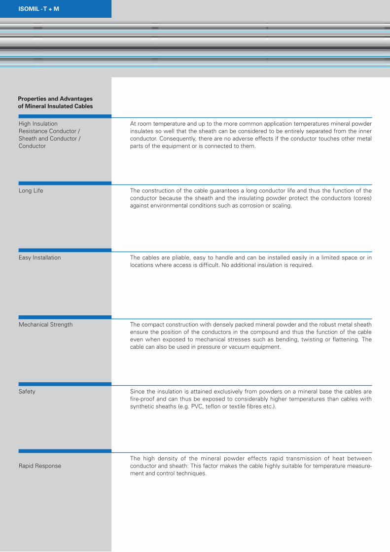
At room temperature and up to the more common application temperatures mineral powder insulates so well that the sheath can be considered to be entirely separated from the inner conductor. Consequently, there are no adverse effects if the conductor touches other metal parts of the equipment or is connected to them.
The construction of the cable guarantees a long conductor life and thus the function of the conductor because the sheath and the insulating powder protect the conductors (cores) against environmental conditions such as corrosion or scaling.
The cables are pliable, easy to handle and can be installed easily in a limited space or in locations where access is difficult. No additional insulation is required.
The compact construction with densely packed mineral powder and the robust metal sheath ensure the position of the conductors in the compound and thus the function of the cable even when exposed to mechanical stresses such as bending, twisting or flattening. The cable can also be used in pressure or vacuum equipment.
Since the insulation is attained exclusively from powders on a mineral base the cables are fire-proof and can thus be exposed to considerably higher temperatures than cables with synthetic sheaths (e.g. PVC, teflon or textile fibres etc.).
The high density of the mineral powder effects rapid transmission of heat between conductor and sheath: This factor makes the cable highly suitable for temperature measure-ment and control techniques.
Properties and Advantages of Mineral Insulated Cables
High InsulationResistance Conductor /Sheath and Conductor /Conductor
Long Life
Easy Installation
Mechanical Strength
Safety
Rapid Response

9
Dielectric Strength
Radiation Resistance
Corrosion andScaling Resistance
Long Lengths
Small Cable Diameter
Despite its small size the compact construction allows an amazingly high dielectric strength conductor/conductor or conductor/sheath, respectively, which means the cables can be used in power supply systems at 220 V and above.
The correct choice of component ensures radiation resistance making possible the use of these cables in primary circuits as well as in the incore area, i.e. inside the actual reactor core.
The vast array of materials included in our standard programme and the possibility to make materials to specification has put us in a position to supply suitable sheath materials even for unfavourable environmental conditions in a corrosive atmosphere and at high temperatures. Depending on the choice of component the maximum application temperatures are between 500°C and 1000°C.
Long lengths of cable can be obtained due to the initial measurements before drawing and the production method.
The relatively small diameter (compared with conventional cables) which is a result of the construction has many advantages for both customer and construction engineer.

ISOMIL -T + M
The conductor or conductors are embedded in high density mineral powder which is herme-tically sealed by a metal sheath. Dimensioning, namely the ratio of wall thickness, insulation layer thickness and conductor diameter, is of significance for the electrical and mechanical properties. Consequently, in the following we present cross-sections of a number of our standard cables as well as some of those made to customer specifications.
The more common cables have diameters between 0.5 and 10 mm. The choice of diameter is primarily determined by the requirements of the technical application in question.
Not all our stock can be supplied in maximum production lengths. When ordering please state the required minimum length, e.g. „1500 m in lengths not under 70 m“.
Components andCommon Properties
Construction of the Cable
Standard Production
The construction of several standard cables of ISOMIL-T, -M cross sections.
Sonderanfertigungen
Some Examples

11
Examples ofcustomer specials
Protection against the absorption of humidity
Special orders are accepted in appropriate amounts. These special requests can be devia-tions from the standard production such as dimensions (sheath thickness, insulation thick-ness, conductor diameter), the number and design of the conductors, the material combina-tion sheath / insulation / inner conductor or special electrical or other physical properties.
As a general rule, special orders are more involved and have as prerequisites a minimum production quantity; in some cases trial runs are required to clarify the position. Moreover the acquisition of materials which are not in stock must be considered.
Discussions with the customers prior to ordering are essential.
The insulation materials are so highly hygroscopic that the mineral powder when exposed through an open end can absorb so much moisture from the atmosphere in a few minutes that the insulation voltage conductor / conductor or conductor / sheath drops by several orders of magnitude.
Consequently, it is vital that the cable ends are kept hermetically sealed at all times, i.e. not only during production but also during further processing and usage. On dispatch both cable ends are moisture sealed with plastic, whereby the inner conductor/conductors are led out so that the insulation voltage can be checked at all times.
However, should moisture penetrate the cable in spite of all the preventive measures, it can be forced out by heating the cable end concerned e.g. with a flame, from the middle to the end. Experience shows that even in a cable which has lain open for several days the moisture does not penetrate more than 50 cm of the cable. It follows that if a cable end lies open over a shorter period then the penetration depth of the humidity is correspondingly less, e.g. a few cms. When drying out the reduction in humidity increases with rising temperature - at 450°C suddenly (MgO). It follows that heating above 500°C has no noteworthy advantages.
ISOMIL -T + M
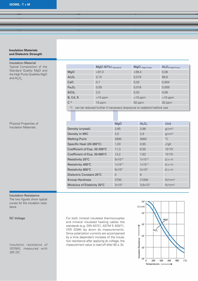
MgO (97%) (Standard) MgO (High Purity) Al2O3 (High Purity)
MgO >97,0 >99,4 0,08
Al2O3 0,15 0,019 99,8
CaO 0,7 0,02 0,004
Fe2O3 0,09 0,018 0,009
5iO22 2,0 0,02 0,08
B, Cd, S <10 ppm <10 ppm <10 ppm
C * 10 ppm 50 ppm 20 ppm
*) can be reduced further if necessary (exposure to radiation) before use.
MgO Al2O3 Unit
Density (crystal) 3,65 3,98 g/cm3
Density in MIC 3,0 2,9 g/cm3
Melting Point 2800 3000 °C
Specifi c Heat (20-300°C) 1,03 0,95 J/gK
Coeffi cient of Exp. 20-200°C 11,3 6,55 10-6/K
Coeffi cient of Exp. 20-600°C 13,2 7,62 10-6/K
Resistivity 20°C 5x10¹⁶ 1x10¹⁴ Ω x m
Resistivity 400°C 1x10¹³ 1x10¹² Ω x m
Resistivity 800°C 5x10⁸ 2x10⁸ Ω x m
Dielectric Constant 20°C 5 9 -
Knoop Hardness 3700 21000 N/mm2
Modulus of Elasticity 20°C 3x10⁵ 3,6x10⁵ N/mm2
For both mineral insulated thermocouples and mineral insulated heating cables the standards (e.g. DIN 43721, ASTM E 420/71, VDE 0284) lay down dc measurements.Since polarization currents are accompanied by a time dependent increase of the insula-tion resistance after applying dc voltage, the measurement value is read off after 60 ± 3s.
Insulation Materialsand Dielectric Strength Insulation MaterialTypical Composition of the Standard Quality MgO and the High Purity Qualities MgO and AI2O3.
Physical Properties ofInsulation Materials:
Insulation ResistanceThe two fi gures show typical curves for the insulation resis-tance.
DC Voltage
Insulation resistance of ISOMIL measured with20V DC.
13
AC Voltage
Insulation resistance of ISOMIL measured with 500V ~ AC / 50Hz.
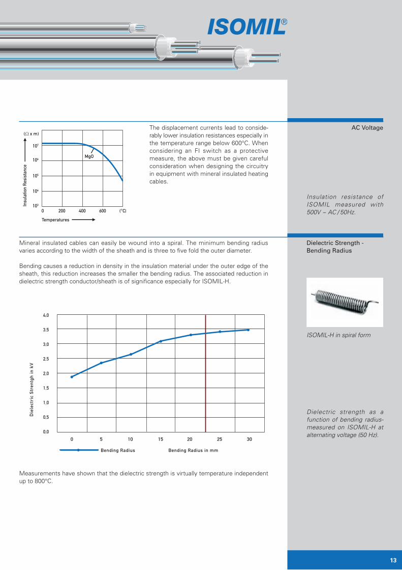
Dielectric Strength -Bending Radius
ISOMIL-H in spiral form
Dielectric strength as a function of bending radius-measured on ISOMIL-H at alternating voltage (50 Hz).
The displacement currents lead to conside-rably lower insulation resistances especially in the temperature range below 600°C. When considering an FI switch as a protective measure, the above must be given careful consideration when designing the circuitry in equipment with mineral insulated heating cables.
Mineral insulated cables can easily be wound into a spiral. The minimum bending radius varies according to the width of the sheath and is three to five fold the outer diameter.
Bending causes a reduction in density in the insulation material under the outer edge of the sheath, this reduction increases the smaller the bending radius. The associated reduction in dielectric strength conductor/sheath is of significance especially for ISOMIL-H.
Measurements have shown that the dielectric strength is virtually temperature independent up to 800°C.
ISOMIL -T + M
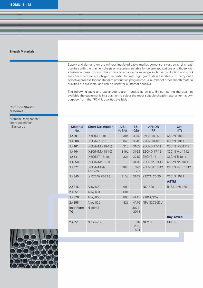
Supply and demand on the mineral insulated cable market comprise a vast array of sheath qualities with the main emphasis on materials suitable for certain applications and those with a historical basis. To limit this choice to an acceptable range as far as production and stock are concerned we are obliged, in particular with high grade stainless steels, to carry out aselective process for our standard production programme . A number of other sheath materialqualities are available, and can be used for customer specials.
The following table and explanations are intended as an aid. By comparing the qualitiesavailable the customer is in a position to select the most suitable sheath material for his own purpose from the ISOMIL qualities available.
Material No.
Short Description AISI(USA)
BS(GB)
AFNOR(FR)
UNI(IT)
1.4301 (X5CrNi 18-9) 304 304S Z6CN 18-09 X5CrNi 1810
1.4306 (X5CrNi 19-11 ) 304L 304S Z2CN 18-10 X3CrNi 1811
1.4401 (X5CrNiMo 18-10) 316 316S Z6CND 17-11 X5CrNi MO1712
1.4404 (X2CrNiMo 18-10) 316L 316S Z2CND 17-12 X2CrNiMo 1712
1.4541 (X6CrNiTi 18-10) 321 321S Z6CNT 18-11 X6CrNiTi 1811
1.4550 (X6CrNiNb18-10) 347S Z6CNNb 18-11 X6CrNiNb 1811
1.4571 (X6CrNiMoTi17-12-2)
316TI 320S31
Z6CNDT 17-12 X6CrNiMoTi 1712
1.4845 (X12CrNi 25-21 ) 310S 310S Z12CN 25-20 X6CrNi 2521
ASTM
2.4816 Alloy 600 600 NC15Fe B163. 166-168
2.4851 Alloy 601 601
1.4876 Alloy 800 800 NA15 Z10NG32-21
2.4858 Alloy 825 825 NA16 NFe 32C20DU
Incotherm TG
Nicromil 3072-3074
Roy. Swed.
2.4951 Nimonic 75 HR 203, 504
NC20T MH. 05
Sheath Materials
Common SheathMaterials
Material Designation /short description- Standards

15
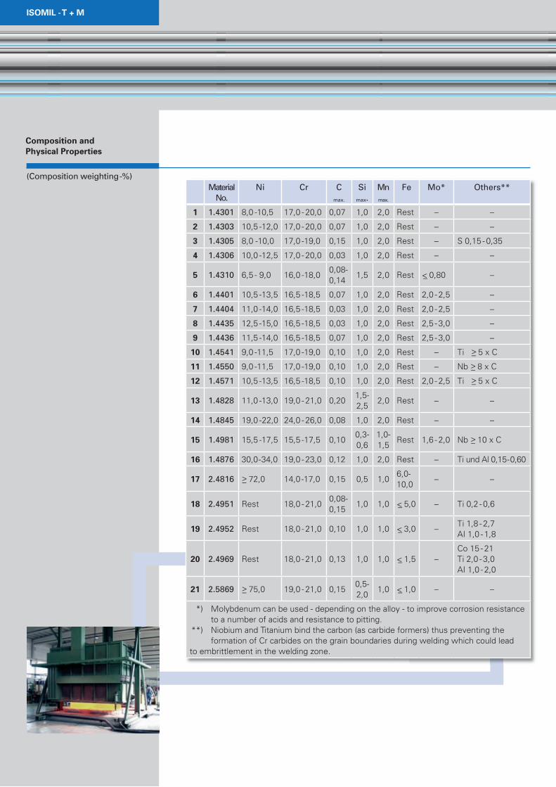
Composition and Physical Properties
(Composition of SheathMaterial wt.-%)
Material No.
Ni Cr Cmax.
Simax.
Mnmax.
Fe Mo* Others**
1.4301 8,0-10,5 17,0-20,0 0,07 1,0 2,0 Rest
1.4306 10,0-12,0 18,0-20,0 0,03 1,0 2,0 Rest
1.4401 10,5-13,5 16,5-18,5 0,07 1,0 2,0 Rest 2,0-2,5
1.4404 10,0-13,0 16,5-18,5 0,03 1,0 2,0 Rest 2,0-2,5
1.4541 9,0-12,0 17,0-19,0 0,08 1,0 2,0 Rest Ti > 5xC
1.4550 9,0-12,0 17,0-19,0 0,08 1,0 2,0 Rest Nb > 8xC
1.4571 10,5-13,5 16,5-18,5 0,08 1,0 2,0 Rest 2,0-2,5 Ti > 5xC
1.4845 19,0-22,0 24,0-26,0 0,08 1,0 2,0 Rest N < 0,11
1.4876 30,0-34,0 19,0-23,0 0,12 1,0 2,0 RestTi und AI0,15-0,60
2.4858 38,0-46,0 19,5-23,5 0,05 0,5 1,0 2,5-3,5Ti 0,6-1,2Cu 1,5-3,0
2.4816 >72,0 14,0-17,0 0,15 0,5 1,06,0-10,0
2.4851 58,0-63,0 21,0-25,0 0,10 0,5 1,0Ti < 0,5AI 1,0-1,7
Incotherm TG
73,6 22,0 1,4 3,0
2.4951 Rest 18,0-21,00,08-0,15
1,0 1,0 <5,0 Ti 0,2-0,6
*) Molybdenum can be used - depending of the alloy - to improve corrosion resistance to a number of acids and resistance to pitting.
**) Niobium and Titanium bind the carbon (as carbide formers) thus preventing the formation of Cr carbides on the grain boundaries during welding which could lead to embrittlement in the welding zone.

ISOMIL -T + M
Corrosion and heat resistance: This material possesses excellent resistance to a number of aggressive media including hot crude oil products, steam and combustion gases. When operated in air it is oxidation resistant up to 900°C and with temperature variation resistant up to 800°C. It is resistant to carbon dioxide up to 650°C.
Welding and mechanical properties: Suitable for all the known welding techniques. It is alloyed with Ti, a carbide former, and is thus resistant to grain disintegration in accordance with DIN 50914. Consequently, irrespective of the cross-section no heat-treatment is required subsequent to welding. The material is highly ductile. Machine-cutting may only be performed with very sharp tools otherwise work hardening of the surface occurs making further processing difficult.
Field of application: Nuclear power (also liquid sodium), reactor instrumentation, construction of chemical instruments (highly resistant), e.g. in the production of acetyl acid and nitric acids, heat exchangers, annealing furnaces, paper and textile industry, crude oil refinement and petrochemistry, fat and soap industry, food processing, dairy and fermentation works.
Corrosion and heat resistance: Additions of molybdenum make these steels superior to molybdenum-free types as regards increased corrosion resistance to certain acids such as acetic acid, phosphoric acid, sulphuric acid, and other similar acids. Furthermore, these steels are more or less insensitive to pitting corrosion and withstand salt-water and aggressive industrial media. They can be used in continuous operation in air up to approx. 900°C and with temperature variation up to 800°C.
Welding and mechanical properties: Suitable for all the known welding techniques. Heat-treatment subsequent to welding is generally not necessary. In special circumstances when stresses from welding should be reduced to avoid stress-corrosion-cracking heat-treatment should be conducted (e.g. 1/2 h at 900°C). Highly ductile. As with 1.4541 only very sharp tools should be used for machine cutting. The steels can be polished.
Field of application: Due to its high level of resistance to corrosion and pitting corrosion this alloy is ideally suited to applications in the field of chemical instrument construction. Other fields are: nuclear power plants, reactor instrumentation, furnace construction, sulphite, che-mical pulp, textile, dye, fatty acid, photochemical and pharmaceutical industries.
Corrosion and heat resistance: This steel is also highly resistant to a number of aggressive media e.g. crude oil products, steam, combustion gases, colouring agents and liquid sodium. In contrast to alloys such as 1.4301, it is less prone to intercrystalline corrosion due to the lower carbon content. It can be subjected to continuous operation in air up to 900°C and under temperature variation up to 800°C.
Welding and mechanical properties: Suitable for all the known welding techniques. Heat-treatment subsequent to welding is generally not necessary. In special circumstances when stresses from welding should be reduced to avoid stress-corrosion-cracking heat-treatment should be conducted (e.g. 1/2h at 900°C). Highly ductile. As with 1.4541 only very sharp tools should be used for machine-cutting. The steels can be polished.
Selection of SuitableSheath Quality
AISI 321
AISI 316 TiAISI 316
AISI 304L
17
AISI 310
Inconel 600
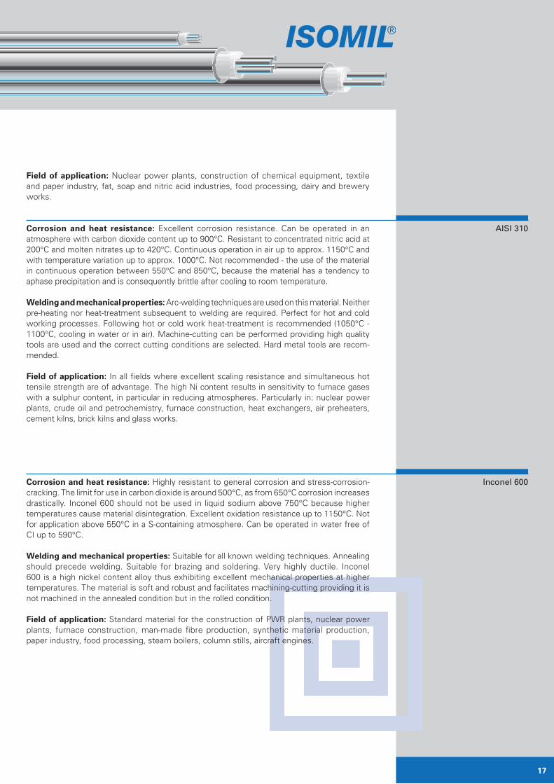
Field of application: Nuclear power plants, construction of chemical equipment, textile and paper industry, fat, soap and nitric acid industries, food processing, dairy and brewery works.
Corrosion and heat resistance: Excellent corrosion resistance. Can be operated in an atmosphere with carbon dioxide content up to 900°C. Resistant to concentrated nitric acid at 200°C and molten nitrates up to 420°C. Continuous operation in air up to approx. 1150°C and with temperature variation up to approx. 1000°C. Not recommended - the use of the material in continuous operation between 550°C and 850°C, because the material has a tendency to aphase precipitation and is consequently brittle after cooling to room temperature.
Welding and mechanical properties: Arc-welding techniques are used on this material. Neither pre-heating nor heat-treatment subsequent to welding are required. Perfect for hot and cold working processes. Following hot or cold work heat-treatment is recommended (1050°C -1100°C, cooling in water or in air). Machine-cutting can be performed providing high quality tools are used and the correct cutting conditions are selected. Hard metal tools are recom-mended.
Field of application: In all fields where excellent scaling resistance and simultaneous hot tensile strength are of advantage. The high Ni content results in sensitivity to furnace gases with a sulphur content, in particular in reducing atmospheres. Particularly in: nuclear power plants, crude oil and petrochemistry, furnace construction, heat exchangers, air preheaters, cement kilns, brick kilns and glass works.
Corrosion and heat resistance: Highly resistant to general corrosion and stress-corrosion- cracking. The limit for use in carbon dioxide is around 500°C, as from 650°C corrosion increases drastically. Inconel 600 should not be used in liquid sodium above 750°C because higher temperatures cause material disintegration. Excellent oxidation resistance up to 1150°C. Not for application above 550°C in a S-containing atmosphere. Can be operated in water free of CI up to 590°C.
Welding and mechanical properties: Suitable for all known welding techniques. Annealing should precede welding. Suitable for brazing and soldering. Very highly ductile. Inconel 600 is a high nickel content alloy thus exhibiting excellent mechanical properties at higher temperatures. The material is soft and robust and facilitates machining-cutting providing it is not machined in the annealed condition but in the rolled condition.
Field of application: Standard material for the construction of PWR plants, nuclear power plants, furnace construction, man-made fibre production, synthetic material production, paper industry, food processing, steam boilers, column stills, aircraft engines.

ISOMIL -T + M
Basicvalues to:
IEC 584 (BRD)
ASTM E230-93 (USA)*
BS 4937/4 (UK)*
NFC 42-321 (FR)*
GOST(GUS)
Temperature °C Basic values in mV
NiCr-Ni
20 0.798 0.798 0.798 0.798 0.80
100 4.095 4.095 4.095 4.095 4.10
200 8.137 8.137 8.137 8.137 813
300 12.207 12.207 12.207 12.207 1.221
400 16.395 16.395 16.395 16.395 1.640
500 20.640 20.640 20.640 20.640 2.065
600 24.902 24.902 24.902 24.902 24.91
700 29.128 29.128 29.128 29.128 29.15
800 33.277 33.277 33.277 33.277 33.32
900 37.325 37.325 37.325 37.325 37.37
1000 41.269 41.269 41.269 41.269 41.32
1100 45.108 45.108 45.108 45.108 45.16
Fe-CuNi (Typ J)
20 1.019 1.019 1.019 1.019
100 5.268 5.268 5.268 5.268
200 10.777 10.777 10.777 10.777
300 16.325 16.325 16.325 16.325
400 21.846 21.846 21.846 21.846
500 27.388 27.388 27.388 27.388
600 33.096 33.096 33.096 33.096
700 39.130 39.130 39.130 39.130
800 45.498 45.498 45.498 45.498
Cu-CuNi
20 0.789 0.789 0.789 0.789
100 4.277 4.277 4.277 4.277
200 9.286 9.286 9.286 9.286
300 14.860 14.860 14.860 14.860
400 20.869 20.869 20.869 20.869
*) Corresponds to IEC 584 New NFC 42-321 is equivalent to IEC 584
Comparison of theStandards
Thermoelectric Voltagesfor temperatures in stepsof 100°C(reference temperature 0°C)

19
Different sheath materials were heated in air in a cycle as follows: 15 min up to 980°C (indirect heating), 5 mins cooling to room temperature, 15 mins up to 980°C and so on.
The diagram below shows the loss in weight (in %) of the specimen versus the test duration (in hours) as a result of the flaking layers of oxide. It is clear that the scaling resistance of the alloys increases with the sum of nickel and chromium, at 980°C with temperature variation it is excellent in INCONEL 600 (2,4816) and still good in 1.4841. On the other hand 18-9 steels are not suitable for applications at this temperature.
Scaling Resistance
ISOMIL -T + M
Composition andPhysical Properties
(Composition weighting-%)Material
No.Ni Cr C
max.
Si max.
Mn max.
Fe Mo* Others**
1 1.4301 8,0 -10,5 17,0 - 20,0 0,07 1,0 2,0 Rest – –
2 1.4303 10,5 -12,0 17,0 - 20,0 0,07 1,0 2,0 Rest – –
3 1.4305 8,0 -10,0 17,0 -19,0 0,15 1,0 2,0 Rest – S 0,15 - 0,35
4 1.4306 10,0 -12,5 17,0 - 20,0 0,03 1,0 2,0 Rest – –
5 1.4310 6,5 - 9,0 16,0 -18,00,08-0,14
1,5 2,0 Rest <_ 0,80 –
6 1.4401 10,5 -13,5 16,5 -18,5 0,07 1,0 2,0 Rest 2,0 - 2,5 –
7 1.4404 11,0 -14,0 16,5 -18,5 0,03 1,0 2,0 Rest 2,0 - 2,5 –
8 1.4435 12,5 -15,0 16,5 -18,5 0,03 1,0 2,0 Rest 2,5 - 3,0 –
9 1.4436 11,5 -14,0 16,5 -18,5 0,07 1,0 2,0 Rest 2,5 - 3,0 –
10 1.4541 9,0 -11,5 17,0 -19,0 0,10 1,0 2,0 Rest – Ti >_ 5 x C
11 1.4550 9,0 -11,5 17,0 -19,0 0,10 1,0 2,0 Rest – Nb >_ 8 x C
12 1.4571 10,5 -13,5 16,5 -18,5 0,10 1,0 2,0 Rest 2,0 - 2,5 Ti >_ 5 x C
13 1.4828 11,0 -13,0 19,0 - 21,0 0,201,5-2,5
2,0 Rest – –
14 1.4845 19,0 -22,0 24,0 - 26,0 0,08 1,0 2,0 Rest – –
15 1.4981 15,5 -17,5 15,5 -17,5 0,100,3-0,6
1,0-1,5
Rest 1,6 - 2,0 Nb >_ 10 x C
16 1.4876 30,0-34,0 19,0 - 23,0 0,12 1,0 2,0 Rest – Ti und Al 0,15-0,60
17 2.4816 >_ 72,0 14,0 -17,0 0,15 0,5 1,06,0-10,0
– –
18 2.4951 Rest 18,0 - 21,00,08-0,15
1,0 1,0 <_ 5,0 – Ti 0,2 - 0,6
19 2.4952 Rest 18,0 - 21,0 0,10 1,0 1,0 <_ 3,0 –Ti 1,8 - 2,7AI 1,0 - 1,8
20 2.4969 Rest 18,0 - 21,0 0,13 1,0 1,0 <_ 1,5 –Co 15 - 21Ti 2,0 - 3,0AI 1,0 - 2,0
21 2.5869 >_ 75,0 19,0 - 21,0 0,150,5-2,0
1,0 <_ 1,0 – –
*) Molybdenum can be used - depending on the alloy - to improve corrosion resistance to a number of acids and resistance to pitting. **) Niobium and Titanium bind the carbon (as carbide formers) thus preventing the formation of Cr carbides on the grain boundaries during welding which could leadto embrittlement in the welding zone.
21
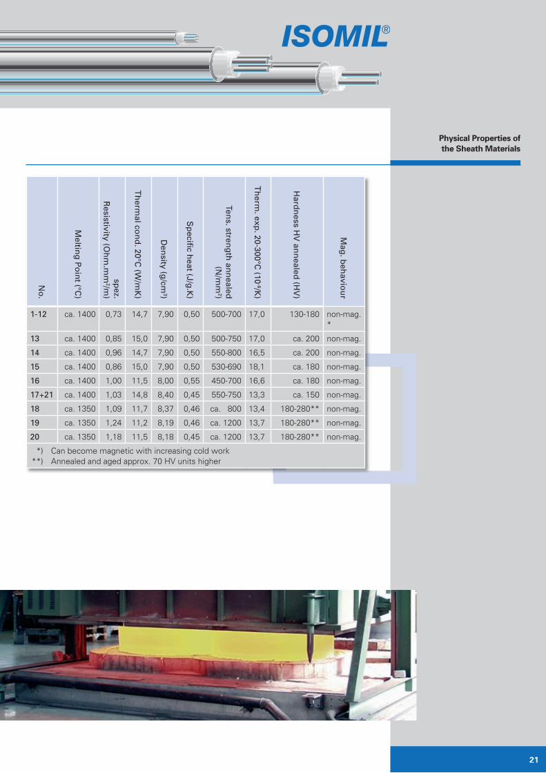
Physical Properties ofthe Sheath Materials
No
.
Meltin
g P
oin
t (°C)
spez.
Resistivity (O
hm
.mm
2/m)
Th
ermal co
nd
. 20°C (W
/mK
)
Den
sity (g/cm
3)
Sp
ecifi c heat (J/g
.K)
Tens. stren
gth
ann
ealed
(N/m
m2)
Th
erm. exp
. 20-300°C (10
-6/K)
Hard
ness H
V an
nealed
(HV
)
Mag
. beh
aviou
r
1-12 ca. 1400 0,73 14,7 7,90 0,50 500-700 17,0 130-180 non-mag. *
13 ca. 1400 0,85 15,0 7,90 0,50 500-750 17,0 ca. 200 non-mag.
14 ca. 1400 0,96 14,7 7,90 0,50 550-800 16,5 ca. 200 non-mag.
15 ca. 1400 0,86 15,0 7,90 0,50 530-690 18,1 ca. 180 non-mag.
16 ca. 1400 1,00 11,5 8,00 0,55 450-700 16,6 ca. 180 non-mag.
17+21 ca. 1400 1,03 14,8 8,40 0,45 550-750 13,3 ca. 150 non-mag.
18 ca. 1350 1,09 11,7 8,37 0,46 ca. 800 13,4 180-280** non-mag.
19 ca. 1350 1,24 11,2 8,19 0,46 ca. 1200 13,7 180-280** non-mag.
20 ca. 1350 1,18 11,5 8,18 0,45 ca. 1200 13,7 180-280** non-mag.
*) Can become magnetic with increasing cold work **) Annealed and aged approx. 70 HV units higher

ISOMIL -T + M
Corrosion Resistanceof Sheath Materials
Corrosive MediaMeterial No. in accordance with AISI
304 305 303 304 L 301 316 316 L 317 D 319 321 347 316 Ti 600
Tap water, 20°C 0 0 0 0 0 0 0 0 0 0 0 0 0
Saltwater, 20°C 0*) 0*) 0*) 0*) 0*) 0*) 0*) 0*) 0*) 0*) 0*) 0*) 0*)
Steam (water vapour), 400°C 0 0 0 0 0 0 0 0 0 0 0 0 0
Steam + SO2 1 1 2 1 1 0 0 0 0 1 1 0 –
Air, 20°C 0 0 0 0 0 0 0 0 0 0 0 0 0
Hydrogen chloride, 20°C 1*) 1*) –*) 1*) 1*) 1*) 1*) 1*) 1*) 1*) 1*) 1*) 1*)
Hydrogen chloride, 100°C 2*) 2*) –*) 2*) 2*) 1*) 1*) 1*) 1*) 2*) 2*) 1*) 1*)
Sulphuric acid, 5%, 20°C 1 1 – 1 1 0 0 0 0 1 1 0 1
Sulphuric acid, 5%, 100°C 3 3 – 3 3 2 2 2 2 3 3 2 3
Hydrochloric acid, 1%, 20°C 1 1 – 1 1 1 1 1 1 1 1 1 1
Hydrochloric acid, 1%, 100°C 3 3 – 3 3 3 3 3 3 3 3 3 3
Lactic acid, 10%, 20°C 0 0 – 0 0 0 0 0 0 0 0 0 0
Lactic acid, 10%, 100°C 0 0 – 0 0 0 0 0 0 0 0 0 1
Nitric acid, 10%, 20°C 0 0 0 0 0 0 0 0 0 0 0 0 0
Nitric acid, 10%, 100°C 0 0 0 0 0 0 0 0 0 0 0 0 0
Lubricating oil, 50°C 0 0 0 0 0 0 0 0 0 0 0 0 0
Household washing powder 0 0 0 0 0 0 0 0 0 0 0 0 0
Sodium chloride, saturated, 20°C 0*) 0*) 0*) 0*) 0*) 0*) 0*) 0*) 0*) 0*) 0*) 0*) 0*)
Sodium chloride, saturated, 100°C 1*) 1*) 1*) 1*) 1*) 1*) 1*) 1*) 1*) 1*) 1*) 1*) 1*)
Petrol, 20°C 0 – 0 0 0 0 0 0 0 0 0 0 0
Petrol + methanol, 15% 0 – 0 0 0 0 0 0 0 0 0 0 0
Sodium hydroxide, 25%, 20°C 0 0 – 0 0 0 0 0 0 0 0 0 0
Sodium hydroxide, 25%, 100°C 1 1 – 1 1 1 1 1 1 1 1 1 0
Sodium hydroxide, 320°C 3 3 – 3 3 3 3 3 3 3 3 3 2
Ammonia, 20°C 0 0 – 0 0 0 0 0 0 0 0 0 0
Lime, 10%, 20°C 0 0 – 0 0 0 0 0 0 0 0 0 0

23
Corrosive MediaMeterial No. in accordance with AISI
304 305 303 304 L 301 316 316 L 317 D 319 321 347 316 Ti 600
Tap water, 20°C 0 0 0 0 0 0 0 0 0 0 0 0 0
Saltwater, 20°C 0*) 0*) 0*) 0*) 0*) 0*) 0*) 0*) 0*) 0*) 0*) 0*) 0*)
Steam (water vapour), 400°C 0 0 0 0 0 0 0 0 0 0 0 0 0
Steam + SO2 1 1 2 1 1 0 0 0 0 1 1 0 –
Air, 20°C 0 0 0 0 0 0 0 0 0 0 0 0 0
Hydrogen chloride, 20°C 1*) 1*) –*) 1*) 1*) 1*) 1*) 1*) 1*) 1*) 1*) 1*) 1*)
Hydrogen chloride, 100°C 2*) 2*) –*) 2*) 2*) 1*) 1*) 1*) 1*) 2*) 2*) 1*) 1*)
Sulphuric acid, 5%, 20°C 1 1 – 1 1 0 0 0 0 1 1 0 1
Sulphuric acid, 5%, 100°C 3 3 – 3 3 2 2 2 2 3 3 2 3
Hydrochloric acid, 1%, 20°C 1 1 – 1 1 1 1 1 1 1 1 1 1
Hydrochloric acid, 1%, 100°C 3 3 – 3 3 3 3 3 3 3 3 3 3
Lactic acid, 10%, 20°C 0 0 – 0 0 0 0 0 0 0 0 0 0
Lactic acid, 10%, 100°C 0 0 – 0 0 0 0 0 0 0 0 0 1
Nitric acid, 10%, 20°C 0 0 0 0 0 0 0 0 0 0 0 0 0
Nitric acid, 10%, 100°C 0 0 0 0 0 0 0 0 0 0 0 0 0
Lubricating oil, 50°C 0 0 0 0 0 0 0 0 0 0 0 0 0
Household washing powder 0 0 0 0 0 0 0 0 0 0 0 0 0
Sodium chloride, saturated, 20°C 0*) 0*) 0*) 0*) 0*) 0*) 0*) 0*) 0*) 0*) 0*) 0*) 0*)
Sodium chloride, saturated, 100°C 1*) 1*) 1*) 1*) 1*) 1*) 1*) 1*) 1*) 1*) 1*) 1*) 1*)
Petrol, 20°C 0 – 0 0 0 0 0 0 0 0 0 0 0
Petrol + methanol, 15% 0 – 0 0 0 0 0 0 0 0 0 0 0
Sodium hydroxide, 25%, 20°C 0 0 – 0 0 0 0 0 0 0 0 0 0
Sodium hydroxide, 25%, 100°C 1 1 – 1 1 1 1 1 1 1 1 1 0
Sodium hydroxide, 320°C 3 3 – 3 3 3 3 3 3 3 3 3 2
Ammonia, 20°C 0 0 – 0 0 0 0 0 0 0 0 0 0
Lime, 10%, 20°C 0 0 – 0 0 0 0 0 0 0 0 0 0

ISOMIL -T + M
Thermoelectric Voltagesin mV
NiCr-Ni
Fe-CuNi
Cu-CuNi°C 0 -10 -20 -30 -40 -50 -60 -70 -80 -90 -100 mV/K*)
-100 -3,40 -3,68 -3,95 -4,21 -4,46 -4,69 -4,91 -5,12 -5,32 -5,51 -5,70 0,023
0 0 -0,39 -0,77 -1,14 -1,50 -1,85 -2,18 -2,50 -2,81 -3,11 -3,40 0,034
°C 0 10 20 30 40 50 60 70 80 90 100
0 0 0,40 0,80 1,21 1,63 2,05 2,48 2,91 3,35 3,80 4,25 0,043
100 4,25 4,71 5,18 5,65 6,13 6,62 7,12 7,63 8,15 8,67 9,20 0,050
200 9,20 9,74 10,29 10,85 11,41 11,98 12,55 13,13 13,71 14,30 14,90 0,057
300 14,90 15,50 16,10 16,70 17,31 17,92 18,53 19,14 19,76 20,38 21,00 0,061
400 21,00 21,62 22,25 22,88 23,51 24,15 24,79 25,44 26,09 26,75 27,41 0,064
500 27,41 28,08 28,75 29,43 30,11 30,80 31,49 32,19 32,89 33,6 34,31 0,069
°C 0 -10 -20 -30 -40 -50 -60 -70 -80 -90 -100 mV/K*)
-100 -3,553 -3,852 -4,138 -4,410 -4,669 -4,912 -5,141 -5,354 -5,550 -5,730 -5,891
0 0 -0,392 -0,777 -1,156 -1,527 -1,889 -2,243 -2,586 -2,920 -3,242 -3,553
°C 0 10 20 30 40 50 60 70 80 90 100
0 0 0,397 0,798 1,203 1,611 2,022 2,436 2,850 3,266 3,681 4,095 0,041
100 4,095 4,508 4,919 5,327 5,733 6,137 6,539 6,939 7,338 7,737 8,137 0,040
200 8,137 8,537 8,938 9,341 9,745 10,151 10,560 10,969 11,381 11,793 12,207 0,041
300 12,207 12,623 13,039 13,456 13,874 14,292 14,712 15,132 15,552 15,974 16,395 0,042
400 16,395 16,818 17,241 17,664 18,088 18,513 18,938 19,363 19,788 20,214 20,640 0,042
500 20,640 21,066 21,493 21,919 22,346 22,772 23,198 23,624 24,050 24,476 24,902 0,043
600 24,902 25,327 25,751 26,176 26,599 27,022 27,445 27,867 28,288 28,709 29,128 0,042
700 29,128 29,547 29,965 30,383 30,799 31,214 31,629 32,042 32,455 32,866 33,277 0,042
800 33,277 33,686 34,095 34,502 34,909 35,314 35,718 36,121 36,524 36,925 37,325 0,041
900 37,325 37,724 38,122 38,519 38,915 39,310 39,703 40,096 40,488 40,879 41,269 0,040
1000 41,269 41,657 42,045 42,432 42,817 43,202 43,585 43,968 44,349 44,729 45,108 0,039
°C 0 -10 -20 -30 -40 -50 -60 -70 -80 -90 -100 mV/K*)
-100 -4,75 -5,15 -5,53 -5,90 -6,26 -6,60 -6,93 -7,25 -7,56 -7,86 -8,15 0,034
0 0 -0,51 -1,02 -1,53 -2,03 -2,51 -2,98 -3,44 -3,89 -4,33 -4,75 0,048
°C 0 10 20 30 40 50 60 70 80 90 100
0 0 0,52 1,05 1,58 2,11 2,65 3,19 3,73 4,27 4,82 5,37 0,054
100 5,37 5,92 6,47 7,03 7,59 8,15 8,71 9,27 9,83 10,39 10,95 0,056
200 10,95 11,51 12,07 12,63 13,19 13,75 14,31 14,88 15,44 16,00 16,56 0,056
300 16,56 17,12 17,68 18,24 18,80 19,36 19,92 20,48 21,04 21,60 22,16 0,056
400 22,16 22,72 23,29 23,86 24,43 25,00 25,57 26,14 26,71 27,28 27,85 0,057
500 27,85 28,43 29,01 29,59 30,17 30,75 31,33 31,91 32,49 33,08 33,67 0,058
600 33,67 34,26 34,85 35,44 36,04 36,64 37,25 37,85 38,47 39,09 39,72 0,061
700 39,72 40,35 40,98 41,62 42,27 42,92 43,57 44,23 44,89 45,55 46,22 0,065
800 46,22 46,89 47,57 48,25 48,94 49,63 50,32 51,02 51,72 52,43 53,14 0,069

25
Thermoelectric Voltagesin mV for Temperatures
in steps of 10°C(reference temperature 0°C)
IEC 584
*) mean value of the100°C range
Thermoelectric Voltagesin mV for Temperatures
in steps of 10°C(reference temperature 0°C)
IEC 584
*) mean value of the100°C range
Thermoelectric Voltagesin mV for Temperatures
in steps of 10°C(reference temperature 0°C)
IEC 584
*) mean value of the100°C range
°C 0 -10 -20 -30 -40 -50 -60 -70 -80 -90 -100 mV/K*)
-100 -3,40 -3,68 -3,95 -4,21 -4,46 -4,69 -4,91 -5,12 -5,32 -5,51 -5,70 0,023
0 0 -0,39 -0,77 -1,14 -1,50 -1,85 -2,18 -2,50 -2,81 -3,11 -3,40 0,034
°C 0 10 20 30 40 50 60 70 80 90 100
0 0 0,40 0,80 1,21 1,63 2,05 2,48 2,91 3,35 3,80 4,25 0,043
100 4,25 4,71 5,18 5,65 6,13 6,62 7,12 7,63 8,15 8,67 9,20 0,050
200 9,20 9,74 10,29 10,85 11,41 11,98 12,55 13,13 13,71 14,30 14,90 0,057
300 14,90 15,50 16,10 16,70 17,31 17,92 18,53 19,14 19,76 20,38 21,00 0,061
400 21,00 21,62 22,25 22,88 23,51 24,15 24,79 25,44 26,09 26,75 27,41 0,064
500 27,41 28,08 28,75 29,43 30,11 30,80 31,49 32,19 32,89 33,6 34,31 0,069
°C 0 -10 -20 -30 -40 -50 -60 -70 -80 -90 -100 mV/K*)
-100 -3,553 -3,852 -4,138 -4,410 -4,669 -4,912 -5,141 -5,354 -5,550 -5,730 -5,891
0 0 -0,392 -0,777 -1,156 -1,527 -1,889 -2,243 -2,586 -2,920 -3,242 -3,553
°C 0 10 20 30 40 50 60 70 80 90 100
0 0 0,397 0,798 1,203 1,611 2,022 2,436 2,850 3,266 3,681 4,095 0,041
100 4,095 4,508 4,919 5,327 5,733 6,137 6,539 6,939 7,338 7,737 8,137 0,040
200 8,137 8,537 8,938 9,341 9,745 10,151 10,560 10,969 11,381 11,793 12,207 0,041
300 12,207 12,623 13,039 13,456 13,874 14,292 14,712 15,132 15,552 15,974 16,395 0,042
400 16,395 16,818 17,241 17,664 18,088 18,513 18,938 19,363 19,788 20,214 20,640 0,042
500 20,640 21,066 21,493 21,919 22,346 22,772 23,198 23,624 24,050 24,476 24,902 0,043
600 24,902 25,327 25,751 26,176 26,599 27,022 27,445 27,867 28,288 28,709 29,128 0,042
700 29,128 29,547 29,965 30,383 30,799 31,214 31,629 32,042 32,455 32,866 33,277 0,042
800 33,277 33,686 34,095 34,502 34,909 35,314 35,718 36,121 36,524 36,925 37,325 0,041
900 37,325 37,724 38,122 38,519 38,915 39,310 39,703 40,096 40,488 40,879 41,269 0,040
1000 41,269 41,657 42,045 42,432 42,817 43,202 43,585 43,968 44,349 44,729 45,108 0,039
°C 0 -10 -20 -30 -40 -50 -60 -70 -80 -90 -100 mV/K*)
-100 -4,75 -5,15 -5,53 -5,90 -6,26 -6,60 -6,93 -7,25 -7,56 -7,86 -8,15 0,034
0 0 -0,51 -1,02 -1,53 -2,03 -2,51 -2,98 -3,44 -3,89 -4,33 -4,75 0,048
°C 0 10 20 30 40 50 60 70 80 90 100
0 0 0,52 1,05 1,58 2,11 2,65 3,19 3,73 4,27 4,82 5,37 0,054
100 5,37 5,92 6,47 7,03 7,59 8,15 8,71 9,27 9,83 10,39 10,95 0,056
200 10,95 11,51 12,07 12,63 13,19 13,75 14,31 14,88 15,44 16,00 16,56 0,056
300 16,56 17,12 17,68 18,24 18,80 19,36 19,92 20,48 21,04 21,60 22,16 0,056
400 22,16 22,72 23,29 23,86 24,43 25,00 25,57 26,14 26,71 27,28 27,85 0,057
500 27,85 28,43 29,01 29,59 30,17 30,75 31,33 31,91 32,49 33,08 33,67 0,058
600 33,67 34,26 34,85 35,44 36,04 36,64 37,25 37,85 38,47 39,09 39,72 0,061
700 39,72 40,35 40,98 41,62 42,27 42,92 43,57 44,23 44,89 45,55 46,22 0,065
800 46,22 46,89 47,57 48,25 48,94 49,63 50,32 51,02 51,72 52,43 53,14 0,069

ISOMIL -T + M
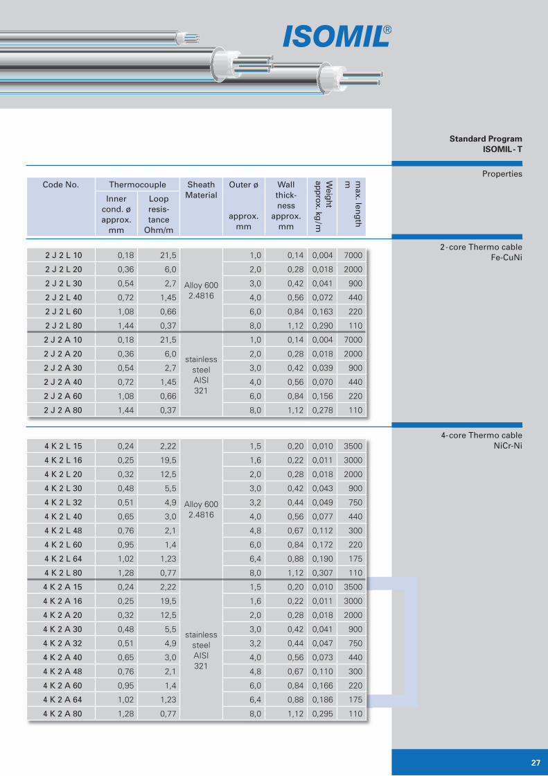
Properties
2-core Thermo cableNiCr-Ni
Further dimensions are onrequest available
Standard ProgramISOMIL- T
Code No. Thermocouple Sheath Material
Outer ø
approx. mm
Wall thick-ness
approx. mm
Weight
approx. kg/m
max. len
gth
m
Inner cond. øapprox.
mm
Loopresis-tance
Ohm/m
2 K 2 L 10 0,18 37,5
Alloy 6002.4816
1,0 0,14 0,004 7000
2 K 2 L 15 0,27 16,5 1,5 0,20 0,010 3500
2 K 2 L 16 0,29 14,6 1,6 0,22 0,011 3000
2 K 2 L 20 0,36 9,6 2,0 0,28 0,018 2000
2 K 2 L 30 0,54 4,3 3,0 0,42 0,041 900
2 K 2 L 32 0,57 3,78 3,2 0,44 0,047 750
2 K 2 L 45 0,72 2,4 4,5 0,56 0,076 380
2 K 2 L 48 0,86 1,66 4,8 0,67 0,118 300
2 K 2 L 60 1,08 1,1 6,0 0,84 0.164 220
2 K 2 L 64 1,15 0,96 6,4 0,88 0,186 175
2 K 2 L 80 1,44 0,60 8,0 1,12 0,291 110
2 K 2 L 100 1,80 0,38 10,0 1,40 0,455 70
2 K 2 A 10 0,18 37,5
stainless steelAISI321
1,0 0,14 0,004 7000
2 K 2 A 15 0,27 16,5 1,5 0,20 0,010 3500
2 K 2 A 16 0,29 14,6 1,6 0,22 0,011 3000
2 K 2 A 20 0,36 9,6 2,0 0,28 0,018 2000
2 K 2 A 30 0,54 4,3 3,0 0,42 0,039 900
2 K 2 A 32 0,57 3,78 3,2 0,44 0,045 750
2 K 2 A 40 0,72 2,4 4,0 0,56 0,070 380
2 K 2 A 48 0,86 1,66 4,8 0,67 0,108 300
2 K 2 A 60 1,08 1,1 6,0 0,84 0,157 220
2 K 2 A 64 1,15 0,96 6,4 0,88 0,182 175
2 K 2 A 80 1,44 0,60 8,0 1,12 0,279 110
2 K 2 A 100 1,80 0,38 10,0 1,4 0,436 70
2 K 2 S 15 0,27 16,5
stainless steelAISI316
1,5 0,20 0,010 3500
2 K 2 S 16 0,29 14,6 1,6 0,22 0,011 3000
2 K 2 S 32 0,57 3,78 3,2 0,44 0,045 750
2 K 2 S 48 0,86 1,66 4,8 0,67 0,108 300
2 K 2 S 64 1,15 0,96 6,4 0,88 0,182 175
27
Properties
2-core Thermo cableFe-CuNi
4-core Thermo cableNiCr-Ni
Standard ProgramISOMIL- T
Code No. Thermocouple Sheath Material
Outer ø
approx. mm
Wall thick-ness
approx. mm
Weight
approx. kg/m
max. len
gth
m
Inner cond. øapprox.
mm
Loopresis-tance
Ohm/m
4 K 2 L 15 0,24 2,22
Alloy 6002.4816
1,5 0,20 0,010 3500
4 K 2 L 16 0,25 19,5 1,6 0,22 0,011 3000
4 K 2 L 20 0,32 12,5 2,0 0,28 0,018 2000
4 K 2 L 30 0,48 5,5 3,0 0,42 0,043 900
4 K 2 L 32 0,51 4,9 3,2 0,44 0,049 750
4 K 2 L 40 0,65 3,0 4,0 0,56 0,077 440
4 K 2 L 48 0,76 2,1 4,8 0,67 0,112 300
4 K 2 L 60 0,95 1,4 6,0 0,84 0,172 220
4 K 2 L 64 1,02 1,23 6,4 0,88 0,190 175
4 K 2 L 80 1,28 0,77 8,0 1,12 0,307 110
4 K 2 A 15 0,24 2,22
stainless steelAISI321
1,5 0,20 0,010 3500
4 K 2 A 16 0,25 19,5 1,6 0,22 0,011 3000
4 K 2 A 20 0,32 12,5 2,0 0,28 0,018 2000
4 K 2 A 30 0,48 5,5 3,0 0,42 0,041 900
4 K 2 A 32 0,51 4,9 3,2 0,44 0,047 750
4 K 2 A 40 0,65 3,0 4,0 0,56 0,073 440
4 K 2 A 48 0,76 2,1 4,8 0,67 0,110 300
4 K 2 A 60 0,95 1,4 6,0 0,84 0,166 220
4 K 2 A 64 1,02 1,23 6,4 0,88 0,186 175
4 K 2 A 80 1,28 0,77 8,0 1,12 0,295 110
2 J 2 L 10 0,18 21,5
Alloy 6002.4816
1,0 0,14 0,004 7000
2 J 2 L 20 0,36 6,0 2,0 0,28 0,018 2000
2 J 2 L 30 0,54 2,7 3,0 0,42 0,041 900
2 J 2 L 40 0,72 1,45 4,0 0,56 0,072 440
2 J 2 L 60 1,08 0,66 6,0 0,84 0,163 220
2 J 2 L 80 1,44 0,37 8,0 1,12 0,290 110
2 J 2 A 10 0,18 21,5
stainless steelAISI321
1,0 0,14 0,004 7000
2 J 2 A 20 0,36 6,0 2,0 0,28 0,018 2000
2 J 2 A 30 0,54 2,7 3,0 0,42 0,039 900
2 J 2 A 40 0,72 1,45 4,0 0,56 0,070 440
2 J 2 A 60 1,08 0,66 6,0 0,84 0,156 220
2 J 2 A 80 1,44 0,37 8,0 1,12 0,278 110

ISOMIL -T + M
Properties
4-core Thermo cableNiCr-Ni
4-core Thermo cableFe-CuNi
Standard ProgramISOMIL- T
Code No. Thermocouple Sheath Material
Outer ø
approx. mm
Wall thick-ness
approx. mm
Weight
approx. kg/m
max. len
gth
m
Inner cond. øapprox.
mm
Loopresis-tance
Ohm/m
4 J 2 L 20 0,32 7,7
Alloy 6002.4816
2,0 0,28 0,019 400
4 J 2 L 30 0,4 3,5 3,0 0,42 0,043 400
4 J 2 L 40 0,65 1.9 4,0 0,56 0,076 250
4 J 2 L 60 0,95 0,85 6,0 0,84 0,171 100
4 J 2 L 80 1,28 0,49 8,0 1,12 0,304 60
4 J 2 A 15 0,24 13,6
stainless steelAISI321
1,5 0,20 0,010 3500
4 J 2 A 16 0,25 12,0 1,6 0,22 0,011 3000
4 J 2 A 20 0,32 7,7 2,0 0,28 0,018 400
4 J 2 A 30 0,48 3,5 3,0 0,42 0,041 400
4 J 2 A 32 0,51 3,0 3,2 0,44 0,047 750
4 J 2 A 40 0,65 1,9 4,0 0,56 0,073 250
4 J 2 A 48 0,76 1,32 4,8 0,67 0,110 300
4 J 2 A 60 0,95 0,85 6,0 0,84 0,166 100
4 J 2 A 64 1,02 0,74 6,4 0,88 0,186 175
4 J 2 A 80 1,28 0,49 8,0 1,12 0,292 60
4 J 2 S 15 0,24 13,6
stainless steelAISI316
1,5 0,20 0,010 3500
4 J 2 S 16 0,25 12,0 1,6 0,22 0,011 3000
4 J 2 S 32 0,51 3,0 3,2 0,44 0,047 750
4 J 2 S 48 0,76 1,32 4,8 0,67 0,110 300
4 J 2 S 64 1,02 0,74 6,4 0,88 0,186 175
4 K 2 S 15 0,24 2,22
stainless steelAISI316
1,5 0,20 0,010 3500
4 K 2 S 16 0,25 19,5 1,6 0,22 0,011 3000
4 K 2 S 32 0,51 4,9 3,2 0,44 0,047 750
4 K 2 S 48 0,76 2,1 4,8 0,67 0,110 300
4 K 2 S 64 1,02 1,23 6,4 0,88 0,186 175

29
Properties
6-core Thermo cableNiCr-Ni
Standard ProgramISOMIL- T
Code No. Thermocouple Sheath Material
Outer ø
approx. mm
Wall thick-ness
approx. mm
Weight
approx. kg/m
max. len
gth
m
Inner cond. øapprox.
mm
Loopresis-tance
Ohm/m
6 K 2 L 30 0,39 8,1
Alloy 6002.4816
3,0 0,42 0,044 400
6 K 2 L 40 0,51 4,8 4,0 0,56 0,077 250
6 K 2 L 60 0,76 2,2 6,0 0,84 0,174 100
6 K 2 L 80 1,02 1,2 8,0 1,12 0,310 60
6 K 2 A 30 0,39 8,1
Edelstahl1.4541
3,0 0,42 0,042 400
6 K 2 A 40 0,51 4,8 4,0 0,56 0,074 250
6 K 2 A 60 0,76 2,2 6,0 0,84 0,168 100
6 K 2 A 80 1,02 1,2 8,0 1,12 0,298 60
6 K 2 L 30 0,39 8,1
Alloy 6002.4816
3,0 0,42 0,044 900
6 K 2 L 40 0,51 4,8 4,0 0,56 0,077 440
6 K 2 L 60 0,76 2,2 6,0 0,84 0,174 220
6 K 2 L 80 1,02 1,2 8,0 1,12 0,310 110
6 K 2 A 30 0,39 8,1stainless
steelAISI321
3,0 0,42 0,042 900
6 K 2 A 40 0,51 4,8 4,0 0,56 0,074 440
6 K 2 A 60 0,76 2,2 6,0 0,84 0,168 220
6 K 2 A 80 1,02 1,2 8,0 1,12 0,298 110

ISOMIL -T + M
Standard ProductionProgram ISOMIL- M
Dimensions andProperties
Physical Properties ofthe Conductor Materials
Ou
terd
iameter
(mm
) No. of con-
ductors
Resistance per meterat 20°C (Ohm / m)
Conductordiameter (mm)
Wall th
ickness
of sh
eath
(mm
)
Weight
Cu CuNi NiCu
CuNiNi kg / m
1,0
1
0,20 5,6 0,91 0,33 0,33 0,14 0,004
2,0 0,05 1,4 0,23 0,67 0,67 0,29 0,016
3,0 0,022 0,62 0,10 1,0 1,0 0,43 0,037
4,0 0,013 0,35 0,057 1,3 1,3 0,58 0,065
5,0 0,008 0,22 0,037 1,7 1,7 0,72 0,102
6,0 0,0056 0,16 0,025 2,0 2,0 0,87 0,147
2,0
2
0,20 5,6 0,91 0,33 0,33 0,29 0,015
3,0 0,18 5,1 0,53 0,35 0,44 0,33 0,033
4,0 0,098 2,7 0,30 0,48 0,58 0,44 0,059
5,0 0,063 1,8 0,19 0,59 0,73 0,55 0,092
6,0 0,044 1,2 0,13 0,71 0,89 0,66 0,132
2,0
4
0,24 6,7 0,88 0,3 0,34 0,29 0,016
3,0 0,12 3,4 0,53 0,43 0,44 0,33 0,037
4,0 0,11 3,1 0,39 0,45 0,51 0,44 0,065
5,0 0,071 2,0 0,25 0,56 0,64 0,55 0,101
6,0 0,049 1,4 0,17 0,67 0,77 0,66 0,146
8,0 0,028 0,78 0,10 0,89 1,0 0,88 0,260
3,0
6
0,151 4,2 0,52 0,38 0,44 0,33 0,037
4,0 0,084 2,3 0,29 0,52 0,59 0,44 0,065
5,0 0,081 2,2 0,19 0,52 0,73 0,55 0,102
6,0 0,056 1,6 0,13 0,63 0,89 0,66 0,147
8,0 0,032 0,89 0,07 0,83 1,2 0,88 0,261
Tolerances apply to diameter: in accordance with DIN 177
Inner conductor material
El. resistivity Ohm mm2/m at Highest permis-sible ap-plication tempera-ture °C
20°C 200°C 400°C 600°C 800°C
Cu 0,0175 0,030 0,045 0,059 − 600
CuNi 44 0,490 0,49 0,49 0,51 0,52 700
Ni 0,080 0,172 0,325 0,395 0,407 800

NOTES
Mistakes and
subject to change.

MINERAL INSULATED
CABLES
MiL GmbH
Industriepark Hanau • Halle 4
Ehrichstraße 10 • 63450 Hanau
Tel. +49 (0) 61 81 - 93 15 50
Fax +49 (0) 61 81 - 31 71 0
e-mail [email protected]
internet www.isomil.de
HOW TO FIND US
A3 Frankfurt
Main direction München / Würzburg / Hanau
Next: Direction B45 Hanau
Next: Direction B43a Fulda
Next: Exit Hanau - Hafen
A45 Giessen
Direction: Hanauer Kreuz
(Motorway junction Hanau)
Next: Direction B43a Dieburg
Next: Exit Hanau - Hafen
Now
Turn right direction Hanau-Hafen.
Next left, direction Industriegebiet (Industrial area)
Hafenstraße.
Next right, Ehrichstraße 10, Industriepark Gebäude 4
(Industrial park building No.4) on the left.
���������������
����������������
���������