Embed Size (px)
Citation preview
ManualEN
isoHR685W-x-I-B_D00261_05_M_XXEN/12.2021
Insulation Monitoring Devicefor IT AC systems with galvanically connected rectifiers and inverters and for IT DC systemswith isoData for logging measurement events with ISOsync for capacitive coupled IT-systems
ISOMETER® isoHR685W–D–I–BisoHR685W–S–I–B

Bender GmbH & Co. KGP.O. Box 1161 • 35301 Grünberg • GermanyLondorfer Straße 65 • 35305 Grünberg • GermanyTel.: +49 6401 807-0Fax: +49 6401 807-259Email: [email protected]: www.bender.de
© Bender GmbH & Co. KGAll rights reserved.
Reproduction only with permissionof the publisher.
Subject to change.
Customer service:Service hotline: 0700-BenderHelp (Telephone and Fax)Carl-Benz-Straße 8 • 35305 Grünberg • GermanyTel.:+49 6401 807-760Fax:+49 6401 807-629Email:[email protected]
PLEASE READ THIS MANUAL AND ANY ACCOMPANYING DOCUMENTS CAREFULLY AND KEEP THEM IN A SECURE PLACE FOR FUTURE REFERENCE.
T
3 isoHR685W-x-I-B_D00261_05_M_XXEN/12.2021
1
2
3
4
................................................................................... 15on. . . . . . . . . . . . . . . . . . . . . . . . . . . . . . . . . . . . . . . . . . . . . . . . .15. . . . . . . . . . . . . . . . . . . . . . . . . . . . . . . . . . . . . . . . . . . . . . . . . . . .15. . . . . . . . . . . . . . . . . . . . . . . . . . . . . . . . . . . . . . . . . . . . . . . . . . . .16. . . . . . . . . . . . . . . . . . . . . . . . . . . . . . . . . . . . . . . . . . . . . . . . . . . .16................................................................................... 17ions. . . . . . . . . . . . . . . . . . . . . . . . . . . . . . . . . . . . . . . . . . . . . . . .17
)AC system . . . . . . . . . . . . . . . . . . . . . . . . . . . . . . . . . . . . . . .18C system . . . . . . . . . . . . . . . . . . . . . . . . . . . . . . . . . . . . . . . . . .18 system. . . . . . . . . . . . . . . . . . . . . . . . . . . . . . . . . . . . . . . . . . . .18
supply voltage . . . . . . . . . . . . . . . . . . . . . . . . . . . . . . . . . . . . .18X1 interface . . . . . . . . . . . . . . . . . . . . . . . . . . . . . . . . . . . . . . . .19Ethernet interface ETH. . . . . . . . . . . . . . . . . . . . . . . . . . . . . .20elay interfaces 1 and 2 . . . . . . . . . . . . . . . . . . . . . . . . . . . . .20. . . . . . . . . . . . . . . . . . . . . . . . . . . . . . . . . . . . . . . . . . . . . . . . . . . .20.................................................................................. 21missioning process . . . . . . . . . . . . . . . . . . . . . . . . . . . . . . . . .21ng . . . . . . . . . . . . . . . . . . . . . . . . . . . . . . . . . . . . . . . . . . . . . . . . .21age . . . . . . . . . . . . . . . . . . . . . . . . . . . . . . . . . . . . . . . . . . . . . . . . . .21
and time . . . . . . . . . . . . . . . . . . . . . . . . . . . . . . . . . . . . . . . . . . . . .21m type . . . . . . . . . . . . . . . . . . . . . . . . . . . . . . . . . . . . . . . . . . . . . . .22ling device . . . . . . . . . . . . . . . . . . . . . . . . . . . . . . . . . . . . . . . . . . .22
le . . . . . . . . . . . . . . . . . . . . . . . . . . . . . . . . . . . . . . . . . . . . . . . . . . . . .22nse value Ran1 for alarm 1 . . . . . . . . . . . . . . . . . . . . . . . . . . . .22nse value Ran2 for alarm 2 . . . . . . . . . . . . . . . . . . . . . . . . . . . .22. . . . . . . . . . . . . . . . . . . . . . . . . . . . . . . . . . . . . . . . . . . . . . . . . . . .22ord protection for the ISOMETER® iso685. . . . . . . . . . . .23................................................................................... 24. . . . . . . . . . . . . . . . . . . . . . . . . . . . . . . . . . . . . . . . . . . . . . . . . . . .24) . . . . . . . . . . . . . . . . . . . . . . . . . . . . . . . . . . . . . . . . . . . . . . . . . .24
ive) . . . . . . . . . . . . . . . . . . . . . . . . . . . . . . . . . . . . . . . . . . . . . . . .25ault message. . . . . . . . . . . . . . . . . . . . . . . . . . . . . . . . . . . . . . .25. . . . . . . . . . . . . . . . . . . . . . . . . . . . . . . . . . . . . . . . . . . . . . . . . . . .25. . . . . . . . . . . . . . . . . . . . . . . . . . . . . . . . . . . . . . . . . . . . . . . . . . . .26. . . . . . . . . . . . . . . . . . . . . . . . . . . . . . . . . . . . . . . . . . . . . . . . . . . .26. . . . . . . . . . . . . . . . . . . . . . . . . . . . . . . . . . . . . . . . . . . . . . . . . . . .26. . . . . . . . . . . . . . . . . . . . . . . . . . . . . . . . . . . . . . . . . . . . . . . . . . . .26. . . . . . . . . . . . . . . . . . . . . . . . . . . . . . . . . . . . . . . . . . . . . . . . . . . .27
able of Contents
. Important information ................................................................................61.1 How to use this manual . . . . . . . . . . . . . . . . . . . . . . . . . . . . . . . . . . . . . . . . . . . . . . . . 61.2 Technical support . . . . . . . . . . . . . . . . . . . . . . . . . . . . . . . . . . . . . . . . . . . . . . . . . . . . . 6
1.2.1 End customer support and advice . . . . . . . . . . . . . . . . . . . . . . . . . . . . . . . . . . 61.2.2 Repair . . . . . . . . . . . . . . . . . . . . . . . . . . . . . . . . . . . . . . . . . . . . . . . . . . . . . . . . . . . . . 61.2.3 Customer service . . . . . . . . . . . . . . . . . . . . . . . . . . . . . . . . . . . . . . . . . . . . . . . . . . 6
1.3 Training courses . . . . . . . . . . . . . . . . . . . . . . . . . . . . . . . . . . . . . . . . . . . . . . . . . . . . . . . 71.4 Delivery conditions . . . . . . . . . . . . . . . . . . . . . . . . . . . . . . . . . . . . . . . . . . . . . . . . . . . . 71.5 Storage . . . . . . . . . . . . . . . . . . . . . . . . . . . . . . . . . . . . . . . . . . . . . . . . . . . . . . . . . . . . . . . 71.6 Warranty and liability . . . . . . . . . . . . . . . . . . . . . . . . . . . . . . . . . . . . . . . . . . . . . . . . . . 71.7 Disposal. . . . . . . . . . . . . . . . . . . . . . . . . . . . . . . . . . . . . . . . . . . . . . . . . . . . . . . . . . . . . . . 7
. Safety instructions .......................................................................................82.1 General safety instructions. . . . . . . . . . . . . . . . . . . . . . . . . . . . . . . . . . . . . . . . . . . . . 82.2 Work activities on electrical installations. . . . . . . . . . . . . . . . . . . . . . . . . . . . . . . . 82.3 Device-specific safety information . . . . . . . . . . . . . . . . . . . . . . . . . . . . . . . . . . . . . 82.4 Intended use . . . . . . . . . . . . . . . . . . . . . . . . . . . . . . . . . . . . . . . . . . . . . . . . . . . . . . . . . . 8
. Function .........................................................................................................93.1 Features. . . . . . . . . . . . . . . . . . . . . . . . . . . . . . . . . . . . . . . . . . . . . . . . . . . . . . . . . . . . . . . 93.2 Product description . . . . . . . . . . . . . . . . . . . . . . . . . . . . . . . . . . . . . . . . . . . . . . . . . . . 9
3.2.1 General product description . . . . . . . . . . . . . . . . . . . . . . . . . . . . . . . . . . . . . . . . 93.2.2 Special ISOMETER® characteristics . . . . . . . . . . . . . . . . . . . . . . . . . . . . . . . . . . 9
3.3 Function description . . . . . . . . . . . . . . . . . . . . . . . . . . . . . . . . . . . . . . . . . . . . . . . . . . 93.4 Interfaces . . . . . . . . . . . . . . . . . . . . . . . . . . . . . . . . . . . . . . . . . . . . . . . . . . . . . . . . . . . . 103.5 Self test . . . . . . . . . . . . . . . . . . . . . . . . . . . . . . . . . . . . . . . . . . . . . . . . . . . . . . . . . . . . . . 10
. Device overview .........................................................................................114.1 Dimensions . . . . . . . . . . . . . . . . . . . . . . . . . . . . . . . . . . . . . . . . . . . . . . . . . . . . . . . . . . 114.2 Device variants . . . . . . . . . . . . . . . . . . . . . . . . . . . . . . . . . . . . . . . . . . . . . . . . . . . . . . . 114.3 Connection and panel . . . . . . . . . . . . . . . . . . . . . . . . . . . . . . . . . . . . . . . . . . . . . . . . 124.4 Display elements and device buttons . . . . . . . . . . . . . . . . . . . . . . . . . . . . . . . . . 13
4.4.1 Display elements . . . . . . . . . . . . . . . . . . . . . . . . . . . . . . . . . . . . . . . . . . . . . . . . . . 134.4.2 device buttons . . . . . . . . . . . . . . . . . . . . . . . . . . . . . . . . . . . . . . . . . . . . . . . . . . . . 13
4.5 Operating and navigating . . . . . . . . . . . . . . . . . . . . . . . . . . . . . . . . . . . . . . . . . . . . 144.5.1 Menu selection . . . . . . . . . . . . . . . . . . . . . . . . . . . . . . . . . . . . . . . . . . . . . . . . . . . 144.5.2 List selection . . . . . . . . . . . . . . . . . . . . . . . . . . . . . . . . . . . . . . . . . . . . . . . . . . . . . . 144.5.3 Parameter selection and value adjustment . . . . . . . . . . . . . . . . . . . . . . . . . 144.5.4 Character input . . . . . . . . . . . . . . . . . . . . . . . . . . . . . . . . . . . . . . . . . . . . . . . . . . . 14
5. Mounting ..................5.1 Common informati5.2 Mounting spaces . 5.3 Screw mounting . . 5.4 DIN rail mounting.
6. Connection ...............6.1 Connection condit6.2 Connection to a 3(N6.3 Connection to an A6.4 Connection to a DC6.5 Connection to the 6.6 Connection to the 6.7 Connection to the 6.8 Connection of the r6.9 Terminal covers. . .
7. Commissioning ........7.1 General initial com7.2 Initial commissioni
7.2.1 Setting langu7.2.2 Setting date 7.2.3 Setting syste7.2.4 Select a coup7.2.5 Setting profi7.2.6 Setting respo7.2.7 Setting respo
7.3 Recommissioning. 7.4 Configuring passw
8. Display ......................8.1 Standard display . . 8.2 Fault display (active8.3 Fault display (inact8.4 Acknowledging a f8.5 History memory . . 8.6 Data-isoGraph . . . . 8.7 Initial measuring. . 8.8 ISOnet operation . 8.9 ISOloop operation 8.10 Automatic test . .
isoHR685W-x-I-B_D00261_05_M_XXEN/12.20214
T
9
9.2 (1.12.4) Digital 2 . . . . . . . . . . . . . . . . . . . . . . . . . . . . . . . . . . . . . . . . . . . . . . . 33
. . . . . . . . . . . . . . . . . . . . . . . . . . . . . . . . . . . . . . . . . . . . . . . . . . . 35ettings . . . . . . . . . . . . . . . . . . . . . . . . . . . . . . . . . . . . . . . . . . . 35age . . . . . . . . . . . . . . . . . . . . . . . . . . . . . . . . . . . . . . . . . . . . . . . 35. . . . . . . . . . . . . . . . . . . . . . . . . . . . . . . . . . . . . . . . . . . . . . . . . . . 35e . . . . . . . . . . . . . . . . . . . . . . . . . . . . . . . . . . . . . . . . . . . . . . . . . . . . 35
at (time). . . . . . . . . . . . . . . . . . . . . . . . . . . . . . . . . . . . . . . . . . . . 35mer time . . . . . . . . . . . . . . . . . . . . . . . . . . . . . . . . . . . . . . . . . . . . 35
e. . . . . . . . . . . . . . . . . . . . . . . . . . . . . . . . . . . . . . . . . . . . . . . . . . . . . 35at (date) . . . . . . . . . . . . . . . . . . . . . . . . . . . . . . . . . . . . . . . . . . . . 35
. . . . . . . . . . . . . . . . . . . . . . . . . . . . . . . . . . . . . . . . . . . . . . . . . . . . . 35 server. . . . . . . . . . . . . . . . . . . . . . . . . . . . . . . . . . . . . . . . . . . . . . . 35 . . . . . . . . . . . . . . . . . . . . . . . . . . . . . . . . . . . . . . . . . . . . . . . . . . . . . 35ce . . . . . . . . . . . . . . . . . . . . . . . . . . . . . . . . . . . . . . . . . . . . . . . . 36
te access . . . . . . . . . . . . . . . . . . . . . . . . . . . . . . . . . . . . . . . . . . . . . 36rnet. . . . . . . . . . . . . . . . . . . . . . . . . . . . . . . . . . . . . . . . . . . . . . . . . 36M . . . . . . . . . . . . . . . . . . . . . . . . . . . . . . . . . . . . . . . . . . . . . . . . . . . 36bus/TCP . . . . . . . . . . . . . . . . . . . . . . . . . . . . . . . . . . . . . . . . . . . . 3785 . . . . . . . . . . . . . . . . . . . . . . . . . . . . . . . . . . . . . . . . . . . . . . . . . . 37bus RTU. . . . . . . . . . . . . . . . . . . . . . . . . . . . . . . . . . . . . . . . . . . . . 37
y. . . . . . . . . . . . . . . . . . . . . . . . . . . . . . . . . . . . . . . . . . . . . . . . . . 37htness . . . . . . . . . . . . . . . . . . . . . . . . . . . . . . . . . . . . . . . . . . . . . . . 37omatic dimming . . . . . . . . . . . . . . . . . . . . . . . . . . . . . . . . . . . . . 37ord . . . . . . . . . . . . . . . . . . . . . . . . . . . . . . . . . . . . . . . . . . . . . . . 37sword . . . . . . . . . . . . . . . . . . . . . . . . . . . . . . . . . . . . . . . . . . . . . . . . 37us . . . . . . . . . . . . . . . . . . . . . . . . . . . . . . . . . . . . . . . . . . . . . . . . . . . 37issioning . . . . . . . . . . . . . . . . . . . . . . . . . . . . . . . . . . . . . . . . . 37ackup . . . . . . . . . . . . . . . . . . . . . . . . . . . . . . . . . . . . . . . . . . . . 37tion. . . . . . . . . . . . . . . . . . . . . . . . . . . . . . . . . . . . . . . . . . . . . . . 37y settings . . . . . . . . . . . . . . . . . . . . . . . . . . . . . . . . . . . . . . . . . 38are . . . . . . . . . . . . . . . . . . . . . . . . . . . . . . . . . . . . . . . . . . . . . . . 38date via interface . . . . . . . . . . . . . . . . . . . . . . . . . . . . . . . . . . . . 38date. . . . . . . . . . . . . . . . . . . . . . . . . . . . . . . . . . . . . . . . . . . . . . . . . 38
. . . . . . . . . . . . . . . . . . . . . . . . . . . . . . . . . . . . . . . . . . . . . . . . 38 . . . . . . . . . . . . . . . . . . . . . . . . . . . . . . . . . . . . . . . . . . . . . . . . 38
n ...........................................................................39 . . . . . . . . . . . . . . . . . . . . . . . . . . . . . . . . . . . . . . . . . . . . . . . . .39. . . . . . . . . . . . . . . . . . . . . . . . . . . . . . . . . . . . . . . . . . . . . . . . . .39 . . . . . . . . . . . . . . . . . . . . . . . . . . . . . . . . . . . . . . . . . . . . . . . . .39
9.2 (1.12.5) Buzzer . . . . . . . . . . . . . . . . . . . . . . . . . . . . . . . . . . . . . . . . . . . . . . . . . 339.2 (1.12.6) Analogue . . . . . . . . . . . . . . . . . . . . . . . . . . . . . . . . . . . . . . . . . . . . . . 33
9.2 (2.0) Data measured values . . . . . . . . . . . . . . . . . . . . . . . . . . . . . . . . . . . . 349.2 (3.0) Control. . . . . . . . . . . . . . . . . . . . . . . . . . . . . . . . . . . . . . . . . . . . . . . . . . . 34
9.2 (3.1) TEST. . . . . . . . . . . . . . . . . . . . . . . . . . . . . . . . . . . . . . . . . . . . . . . . . . . . 359.2 (3.2) Reset . . . . . . . . . . . . . . . . . . . . . . . . . . . . . . . . . . . . . . . . . . . . . . . . . . . 359.2 (3.3) Start initial measurement . . . . . . . . . . . . . . . . . . . . . . . . . . . . . . . 359.2 (3.4) EDS . . . . . . . . . . . . . . . . . . . . . . . . . . . . . . . . . . . . . . . . . . . . . . . . . . . . 359.2 (3.5) Device: . . . . . . . . . . . . . . . . . . . . . . . . . . . . . . . . . . . . . . . . . . . . . . . . . 359.2 (3.6) ISOnet priority . . . . . . . . . . . . . . . . . . . . . . . . . . . . . . . . . . . . . . . . . . 35
9.2 (5.11) Service9.2 (6.0) Info. . . . . . .
10. Device communicatio10.1 Ethernet interface . .10.2 BCOM . . . . . . . . . . . . . 10.3 Modbus/TCP . . . . . . .
able of Contents Table of Contents
. Settings ........................................................................................................289.1 Menustructure . . . . . . . . . . . . . . . . . . . . . . . . . . . . . . . . . . . . . . . . . . . . . . . . . . . . . . . 289.2 Settings in the device menu . . . . . . . . . . . . . . . . . . . . . . . . . . . . . . . . . . . . . . . . . . 29
9.2 (1.0) Alarm settings . . . . . . . . . . . . . . . . . . . . . . . . . . . . . . . . . . . . . . . . . . . . 299.2 (1.1) Insulation alarm . . . . . . . . . . . . . . . . . . . . . . . . . . . . . . . . . . . . . . . . 29
9.2 (1.1.1) Alarm 1 . . . . . . . . . . . . . . . . . . . . . . . . . . . . . . . . . . . . . . . . . . . . . . . . . 299.2 (1.1.2) Alarm 2 . . . . . . . . . . . . . . . . . . . . . . . . . . . . . . . . . . . . . . . . . . . . . . . . . 299.2 (1.1.3) Fault memory . . . . . . . . . . . . . . . . . . . . . . . . . . . . . . . . . . . . . . . . . . . 29
9.2 (1.2) DC alarm . . . . . . . . . . . . . . . . . . . . . . . . . . . . . . . . . . . . . . . . . . . . . . . 299.2 (1.2.1) Alarm . . . . . . . . . . . . . . . . . . . . . . . . . . . . . . . . . . . . . . . . . . . . . . . . . . . 299.2 (1.2.2) U(DC-E) . . . . . . . . . . . . . . . . . . . . . . . . . . . . . . . . . . . . . . . . . . . . . . . . . 29
9.2 (1.3) Profile . . . . . . . . . . . . . . . . . . . . . . . . . . . . . . . . . . . . . . . . . . . . . . . . . . 309.2 (1.4) System type . . . . . . . . . . . . . . . . . . . . . . . . . . . . . . . . . . . . . . . . . . . . 309.2 (1.5) Coupling . . . . . . . . . . . . . . . . . . . . . . . . . . . . . . . . . . . . . . . . . . . . . . . 309.2 (1.6) ISOnet. . . . . . . . . . . . . . . . . . . . . . . . . . . . . . . . . . . . . . . . . . . . . . . . . . 30
9.2 (1.6.1) ISOnet . . . . . . . . . . . . . . . . . . . . . . . . . . . . . . . . . . . . . . . . . . . . . . . . . . 309.2 (1.6.2) Number of devices . . . . . . . . . . . . . . . . . . . . . . . . . . . . . . . . . . . . . . 30
9.2 (1.7) ISOloop . . . . . . . . . . . . . . . . . . . . . . . . . . . . . . . . . . . . . . . . . . . . . . . . 309.2 (1.7.1) ISOloop . . . . . . . . . . . . . . . . . . . . . . . . . . . . . . . . . . . . . . . . . . . . . . . . . 309.2 (1.7.2) Measured value subscription . . . . . . . . . . . . . . . . . . . . . . . . . . . . 30
9.2 (1.8) ISOsync. . . . . . . . . . . . . . . . . . . . . . . . . . . . . . . . . . . . . . . . . . . . . . . . . 309.2 (1.9) (Start) . . . . . . . . . . . . . . . . . . . . . . . . . . . . . . . . . . . . . . . . . . . . . . . . . . 309.2 (1.10) Coupling monitoring . . . . . . . . . . . . . . . . . . . . . . . . . . . . . . . . . . 309.2 (1.11) Inputs . . . . . . . . . . . . . . . . . . . . . . . . . . . . . . . . . . . . . . . . . . . . . . . . . 31
9.2 (1.11.1) Digital 1 . . . . . . . . . . . . . . . . . . . . . . . . . . . . . . . . . . . . . . . . . . . . . . . 319.2 (1.11.2) Digital 2 . . . . . . . . . . . . . . . . . . . . . . . . . . . . . . . . . . . . . . . . . . . . . . . 319.2 (1.11.3) Digital 3 . . . . . . . . . . . . . . . . . . . . . . . . . . . . . . . . . . . . . . . . . . . . . . . 31
9.2 (1.12) Outputs . . . . . . . . . . . . . . . . . . . . . . . . . . . . . . . . . . . . . . . . . . . . . . . 319.2 (1.12.1) Relay 1. . . . . . . . . . . . . . . . . . . . . . . . . . . . . . . . . . . . . . . . . . . . . . . . . 319.2 (1.12.2) Relais 2 . . . . . . . . . . . . . . . . . . . . . . . . . . . . . . . . . . . . . . . . . . . . . . . . 329.2 (1.12.3) Digital 1 . . . . . . . . . . . . . . . . . . . . . . . . . . . . . . . . . . . . . . . . . . . . . . . 33
9.2 (4.0) History 9.2 (5.0) Device s
9.2 (5.1) Langu9.2 (5.2) Clock
9.2 (5.2.1) Tim9.2 (5.2.2) Form9.2 (5.2.3) Sum9.2 (5.2.4) Dat9.2 (5.2.5) Form9.2 (5.2.6) NTP9.2 (5.2.7) NTP9.2 (5.2.8) UTC
9.2 (5.3) Interfa9.2 (5.3.1) Wri9.2 (5.3.2) Ethe9.2 (5.3.3) BCO9.2 (5.3.4) Mod9.2 (5.3.5) RS-49.2 (5.3.6) Mod
9.2 (5.4) Displa9.2 (5.4.1) Brig9.2 (5.4.2) Aut
9.2 (5.5) Passw9.2 (5.5.1) Pas9.2 (5.5.2) Stat
9.2 (5.6) Comm9.2 (5.7) Data b9.2 (5.8) Activa9.2 (5.9) Factor9.2 (5.10) Softw
9.2 (5.10.1) Up9.2 (5.10.2) Up
isoHR685W-x-I-B_D00261_05_M_XXEN/12.20215
T
1
11.5.1 System overview ISOsync . . . . . . . . . . . . . . . . . . . . . . . . . . . . . . . . . . . . . . . . . 53
1
..................................................................................57arms . . . . . . . . . . . . . . . . . . . . . . . . . . . . . . . . . . . . . . . . . . . . . .57. . . . . . . . . . . . . . . . . . . . . . . . . . . . . . . . . . . . . . . . . . . . . . . . . . . .57. . . . . . . . . . . . . . . . . . . . . . . . . . . . . . . . . . . . . . . . . . . . . . . . . . . .58. . . . . . . . . . . . . . . . . . . . . . . . . . . . . . . . . . . . . . . . . . . . . . . . . . . .59..................................................................................60HR685W-x-I-B. . . . . . . . . . . . . . . . . . . . . . . . . . . . . . . . . . . . . .605W-x-I-B . . . . . . . . . . . . . . . . . . . . . . . . . . . . . . . . . . . . . . . . . . .61e profile Power circuits . . . . . . . . . . . . . . . . . . . . . . . . . . . . . . 61e profile High capacitance . . . . . . . . . . . . . . . . . . . . . . . . . . . 61e profile Control circuits . . . . . . . . . . . . . . . . . . . . . . . . . . . . . 62 profile Generator . . . . . . . . . . . . . . . . . . . . . . . . . . . . . . . . . . . 62e profile Inverter > 10 Hz . . . . . . . . . . . . . . . . . . . . . . . . . . . . 62e profile Inverter < 10 Hz . . . . . . . . . . . . . . . . . . . . . . . . . . . . 62e DC Alarm . . . . . . . . . . . . . . . . . . . . . . . . . . . . . . . . . . . . . . . . . 63rtainty . . . . . . . . . . . . . . . . . . . . . . . . . . . . . . . . . . . . . . . . . . . . . . 63
oHR685W-x-I-B . . . . . . . . . . . . . . . . . . . . . . . . . . . . . . . . . . . .64R685W-x-I-B . . . . . . . . . . . . . . . . . . . . . . . . . . . . . . . . . . . . . . .65tifications. . . . . . . . . . . . . . . . . . . . . . . . . . . . . . . . . . . . . . . . . .68. . . . . . . . . . . . . . . . . . . . . . . . . . . . . . . . . . . . . . . . . . . . . . . . . . . .68. . . . . . . . . . . . . . . . . . . . . . . . . . . . . . . . . . . . . . . . . . . . . . . . . . . . . . 68. . . . . . . . . . . . . . . . . . . . . . . . . . . . . . . . . . . . . . . . . . . . . . . . . . . . . . 68em components . . . . . . . . . . . . . . . . . . . . . . . . . . . . . . . . . . . . . 68. . . . . . . . . . . . . . . . . . . . . . . . . . . . . . . . . . . . . . . . . . . . . . . . . . . .69. . . . . . . . . . . . . . . . . . . . . . . . . . . . . . . . . . . . . . . . . . . . . . . . . . . .69
11.5.2 Configuration and function . . . . . . . . . . . . . . . . . . . . . . . . . . . . . . . . . . . . . . . 53
2. Coupling devices ......................................................................................5412.1 Connection using the AGH150W-4(DC) . . . . . . . . . . . . . . . . . . . . . . . . . . . . . . 5412.2 Connection using the AGH150W-4(3(N)AC) . . . . . . . . . . . . . . . . . . . . . . . . . . 5412.3 Connection using the AGH520S (3AC). . . . . . . . . . . . . . . . . . . . . . . . . . . . . . . . 5512.4 Connection using the AGH520S (3(N)AC). . . . . . . . . . . . . . . . . . . . . . . . . . . . . 5512.5 Connection using the AGH204S-4. . . . . . . . . . . . . . . . . . . . . . . . . . . . . . . . . . . . 5612.6 Connection using the AGH676S-4. . . . . . . . . . . . . . . . . . . . . . . . . . . . . . . . . . . . 56
able of Contents Table of Contents
10.4 Web server . . . . . . . . . . . . . . . . . . . . . . . . . . . . . . . . . . . . . . . . . . . . . . . . . . . . . . . . . . 3910.4.1 Conventions . . . . . . . . . . . . . . . . . . . . . . . . . . . . . . . . . . . . . . . . . . . . . . . . . . . . . . 3910.4.2 Functions . . . . . . . . . . . . . . . . . . . . . . . . . . . . . . . . . . . . . . . . . . . . . . . . . . . . . . . . . 3910.4.3 User interface . . . . . . . . . . . . . . . . . . . . . . . . . . . . . . . . . . . . . . . . . . . . . . . . . . . . . 4010.4.4 Menu structure . . . . . . . . . . . . . . . . . . . . . . . . . . . . . . . . . . . . . . . . . . . . . . . . . . . 4010.4.5 Parameter changes . . . . . . . . . . . . . . . . . . . . . . . . . . . . . . . . . . . . . . . . . . . . . . . 4110.4.6 Changing parameters in the web browser . . . . . . . . . . . . . . . . . . . . . . . . . 4210.4.7 Changing parameters in the device menu when the
web browser is open . . . . . . . . . . . . . . . . . . . . . . . . . . . . . . . . . . . . . . . . . . . . . . . 4210.4.8 Write access for parameter changes . . . . . . . . . . . . . . . . . . . . . . . . . . . . . . . 42
10.5 BS bus . . . . . . . . . . . . . . . . . . . . . . . . . . . . . . . . . . . . . . . . . . . . . . . . . . . . . . . . . . . . . . 4310.5.1 Master-slave principle . . . . . . . . . . . . . . . . . . . . . . . . . . . . . . . . . . . . . . . . . . . . . 4310.5.2 Addresses and address ranges on the BS bus . . . . . . . . . . . . . . . . . . . . . . 4310.5.3 RS-485 specifications/cables . . . . . . . . . . . . . . . . . . . . . . . . . . . . . . . . . . . . . . 4310.5.4 Cable routing . . . . . . . . . . . . . . . . . . . . . . . . . . . . . . . . . . . . . . . . . . . . . . . . . . . . . 43
10.6 Modbus RTU . . . . . . . . . . . . . . . . . . . . . . . . . . . . . . . . . . . . . . . . . . . . . . . . . . . . . . . . 4310.7 isoData protocol . . . . . . . . . . . . . . . . . . . . . . . . . . . . . . . . . . . . . . . . . . . . . . . . . . . . 44
10.7.1 isoData-protocol table . . . . . . . . . . . . . . . . . . . . . . . . . . . . . . . . . . . . . . . . . . . . 45
1. Special functions for coupled IT systems ............................................4811.1 Particularities when monitoring coupled IT systems . . . . . . . . . . . . . . . . . . 4811.2 System isolation via digital input with two coupled systems . . . . . . . . . . 4811.3 System isolation via ISOnet . . . . . . . . . . . . . . . . . . . . . . . . . . . . . . . . . . . . . . . . . . 48
11.3.1 Systempictures . . . . . . . . . . . . . . . . . . . . . . . . . . . . . . . . . . . . . . . . . . . . . . . . . . . 4911.3.2 Configuration and function . . . . . . . . . . . . . . . . . . . . . . . . . . . . . . . . . . . . . . . 4911.3.3 ISOnet priority . . . . . . . . . . . . . . . . . . . . . . . . . . . . . . . . . . . . . . . . . . . . . . . . . . . . 49
11.4 ISOloop . . . . . . . . . . . . . . . . . . . . . . . . . . . . . . . . . . . . . . . . . . . . . . . . . . . . . . . . . . . . . 5011.4.1 Preparing the devices in an interconnection . . . . . . . . . . . . . . . . . . . . . . . 5011.4.2 Creating groups with the BCOM Group Manager . . . . . . . . . . . . . . . . . . . 5111.4.3 Configuration and function on the ISOMETER® . . . . . . . . . . . . . . . . . . . . . 52
11.5 ISOsync for capacitive couppled IT systems . . . . . . . . . . . . . . . . . . . . . . . . . . 53
13. Alarm messages .....13.1 Measured value al13.2 General. . . . . . . . . . 13.3 ISOnet. . . . . . . . . . . 13.4 ISOloop . . . . . . . . .
14. Technical data ........14.1 Device profiles iso14.2 Diagrams isoHR68
14.2.1 Response tim14.2.2 Response tim14.2.3 Response tim14.2.4 Rsponse time14.2.5 Response tim14.2.6 Response tim14.2.7 Response tim14.2.8 Relative unce
14.3 Factory settings is14.4 Tabular data isoH14.5 Standards and cer14.6 Ordering details .
14.6.1 Device . . . . . 14.6.2 Accessories 14.6.3 Suitable syst
14.7 Glossary . . . . . . . . . 14.8 Change log . . . . . .

isoHR685W-x-I-B_D00261_05_M_XXEN/12.2021
1
1
Thth
rt
pport and advice or e-mail for all Bender productspecific customer applications
7-760 (365 days from 07:00 - 20:00 Uhr [MEZ/UTC +1])7-259Help (Tel. and Fax in Germany only)nder.de
nd replacement service for Bender productsesting and analysing Bender products update for Bender devices t devices-house repair service, replacement devices at no extra cost7-780* (technical issues) 7-784*, -785* (sales)7-789er.de
repair to the following address:
r productster setting, maintenance, troubleshooting
l installation in the building (power quality test, EMC test,
tomers-752*, -762* (technical issues)/-753* (sales)-759bender.de.de00 a.m. - 16:00 p.m. , Fr 07:00 a.m. - 13:00 p.m.
6
This symbol denotes information intended to assist the user in makingoptimum use of the product.
• Commissioning, parame
• Analysis of the electricathermography)
• Training courses for cusTelephone: +49 6401 807
+49 6401 807Fax: +49 6401 807E-mail: fieldservice@Internet: www.bender
* Mo-Thu 07:
Important information. Important information
.1 How to use this manual
o make it easier for you to understand and revisit certain sections in this manual, we ave used symbols to identify important instructions and information. The meaning of ese symbols is explained below.
This manual is intended for qualified personnel working in electricalengineering and electronics!
Read the manual before you begin to mount, connect, and commissionthe unit. Always keep the manual within easy reach for future referencefollowing commissioning.
DANGER
This signal word indicates that there is a high risk of danger that will re-sult in electrocution or serious injury if not avoided.
WARNING
This signal word indicates a medium risk of danger that can lead todeath or serious injury if not avoided.
CAUTION
This signal word indicates a low-level risk that can result in minor ormoderate injury or damage to property if not avoided.
1.2 Technical suppo
1.2.1 End customer suTechnical support by phone • Questions concerning s • Commissioning • TroubleshootingTelephone: +49 6401 80Fax: +49 6401 80
0700BenderE-mail: support@be
1.2.2 RepairRepair, calibration, update a • Repairing, calibrating, t • Hardware and software • Delivery of replacemen • Extended guarantee, inTelephone: +49 6401 80
+49 6401 80Fax: +49 6401 80E-mail: repair@bend
Please send the devices for
Bender GmbH, Repair-Service,Londorfer Strasse 65,35305 Grünberg
1.2.3 Customer serviceOn-site service for all Bende

Im
isoHR685W-x-I-B_D00261_05_M_XXEN/12.20217
1BT
1B
FTEced(ZEfo
S
1Tspe
1We • Failure to observe the instructions in this operating manual regarding transport,
cially the safety instructions, must be observed by all person-urthermore, the rules and regulations that apply for accidentse must be observed.
ations and laws governing the disposal of this device. Ask sure how to dispose of the old equipment.
trical and electronic equipment (WEEE directive) and the di-certain hazardous substances in electrical and electronic apply in the European Community. In Germany, these poli-gh the "Electrical and Electronic Equipment Act" (ElektroG). ing applies:
equipment are not part of household waste.
tors are not part of household waste and must be disposed e regulations.
onic equipment from users other than private households o the market after 13 August 2005 must be taken back by the sed of properly.
e disposal of Bender devices, refer to our homepage at
w.bender.de -> Service & Support.
commissioning, operation and maintenance of the device. • Unauthorised changes to the device made by parties other than the manufacturer. • Non-observance of technical data. • Repairs carried out incorrectly and the use of replacement parts or accessories not
approved by the manufacturer. • Catastrophes caused by external influences and force majeure. • Mounting and installation with device combinations not recommended by the man-
ufacturer.
Important informationportant information
.3 Training coursesender is happy to provide training regarding the use of test equipment. he dates of training courses and workshops can be found on the Internet at
www.bender.de -> Know-how -> Seminars.
.4 Delivery conditionsender sale and delivery conditions apply.
or software products, the "Softwareklausel zur Überlassung von Standard-Software als eil von Lieferungen, Ergänzung und Änderung der Allgemeinen Lieferbedingungen für rzeugnisse und Leistungen der Elektroindustrie" (software clause in respect of the li-
nsing of standard software as part of deliveries, modifications and changes to general elivery conditions for products and services in the electrical industry) set out by the ZVEI entralverband Elektrotechnik- und Elektronikindustrie e.V.) (German Electrical and
lectronic Manufacturers' Association) also applies. Amending the “General Conditions r the supply of Products and Services of the Electrical and Electronics Industry” (GL)*
ale and delivery conditions can be obtained from Bender in printed or electronic format.
.5 Storagehe devices must only be stored in areas where they are protected from dust, damp, and
ray and dripping water, and in which the specified storage temperatures can be nsured.
.6 Warranty and liabilityarranty and liability claims in the event of injury to persons or damage to property are
xcluded if they can be attributed to one or more of the following causes: • Improper use of the device. • Incorrect mounting, commissioning, operation and maintenance of the device.
This operating manual, espenel working on the device. Fprevention at the place of u
1.7 DisposalAbide by the national regulyour supplier if you are not
The directive on waste elecrective on the restriction of equipment (RoHS directive)cies are implemented throuAccording to this, the follow
• Electrical and electronic
• Batteries and accumulaof in accordance with th
• Old electrical and electrwhich was introduced tmanufacturer and dispo
For more information on th
ww

isoHR685W-x-I-B_D00261_05_M_XXEN/12.2021
2
2Pin
2
Ifau
safety information
onitors the insulation resistance of unearthed AC/DC main minal system voltages of AC 0…690 V or DC 0…1000 V.
C/DC systems do not influence the operating characteristics. llows de-energised systems to be monitored too. The ma-eakage capacitance is 0…1000 μF, depending on the profile.
all information in the operating manualtervals
ments of applicable standards, customised parameter set-quipment in order to adapt it to local equipment and opera-
the limits of the area of application indicated in the technical
cribed in this manual is regarded as improper.
n inside a control cabinetETER® is installed inside a control cabinet, the insulation faultust be audible and/or visible to attract attention. with several ISOMETER®sthat only one active ISOMETER® is connected in each intercon-tem. If IT systems are interconnected via coupling switches,that ISOMETER®s not currently used are disconnected from thend deactivated. For IT systems coupled via diodes or capaci-ntral control of the different ISOMETER®s is required.easurement errors!nitored IT system contains galvanically coupled DC circuits, an
fault can only be detected correctly if the rectifier valves (e.g.de, thyristors, IGBTs, frequency inverters, …) carry a minimum
10 mA.d frequency rangeecting to an IT system with frequency components below the
equency range, the response times and response values may the indicated technical data. However, depending on the ap-nd the selected measurement method, continuous insulation is also possible in this frequency range.
8
Intended use also implies: • Reading and observing • Compliance with test in
In order to meet the requiretings must be made on the eting conditions. Please heedspecifications.
Any other use than that des
Safety instructions. Safety instructions
.1 General safety instructionsart of the device documentation in addition to this manual is the enclosed "Safety structions for Bender products".
.2 Work activities on electrical installations.
the device is used outside the Federal Republic of Germany, the applicable local stand-rds and regulations must be complied with. The European standard EN 50110 can be sed as a guide.
Read the operating manual before starting to install, connect and com-mission the device. After successful commissioning, keep the manualwithin easy reach for future reference.
Only qualified personnel are permitted to carry out the work necessaryto install, commission and run a device or system.
DANGER
Risk of electrocution due to electric shock!Touching live parts of the system carries the risk of: • A fatal electric shock • Damage to the electrical installation • Destruction of the deviceBefore installing and connecting the device, make sure that the in-stallation has been de-energised. Observe the rules for working on elec-trical installations.
2.3 Device-specific
2.4 Intended useThe ISOMETER® iso685… mcircuits (IT systems) with no
DC components existing in AA separate supply voltage aximum permissible system l
InstallatioIf the ISOMmessage mIT systemsMake sure nected sysmake sure IT system atances a cePrevent mWhen a moinsulation rectifier diocurrent of >UnspecifieWhen connspecified frdiffer fromplication amonitoring

isoHR685W-x-I-B_D00261_05_M_XXEN/12.2021
3
3
3.2 Product description
R® characteristics belongs to the iso685 device family and features an integrat-lies in full to this ISOMETER®.
is the sensor variant from the iso685 device family. The only ant and the ISOMETER® isoHR685-D-B is that it does not have o685–S–P must be used in combination with a front panel . The operation of the front panel is equal to the operation of
grated display, which is described in this manual.
ith integrated display are described. This description is sim-OMETER® sensor variants and the front panel FP200. The al applies will be referred to as ISOMETER®s hereafter.
ptionevice continuously monitors the entire insulation resistance
ation and triggers an alarm when the value falls below a pre-in a measurement the device has to be connected between stem) and the protective earth conductor (PE). A measuring perimposed onto the system which is recorded and evalu-ntrolled measuring circuit. The measuring time is dependent nt profiles, the system leakage capacitance, the insulation re-
-related disturbances.
her parameters are set using a commissioning wizard as well using the device buttons and a high-resolution graphical LC s are stored in a permanent fail-safe memory. Different r the setup menus as well as the messages indicated on the
clock for storing fault messages and events in a history stamp. The settings can be password protected to prevent
g of connection monitoring, the device requires the setting r DC and the required use of the appropriate terminals L1/+,
nsor variant (i.e. ISOMETER® iso685–S–P) can be connected toanel. Connection to the display variant (i.e ISOMETER® iso685– possible.
9
3.2.1 General product descriptionThe ISOMETER® is an insulation monitoring device for IT systems in accordance with IEC 61557-8.
It is universally applicable in AC, 3(N)AC, AC/DC and DC systems. AC systems may include extensive DC-supplied loads (such as rectifiers, inverters, variable-speed drives).
languages can be selected fodisplay. The device utilises amemory with time and dateunauthorised changes.
To ensure proper functioninof the system type 3AC, AC oL2, L3/-.
Function. Function
.1 Features • ISOMETER® for IT AC systems with galvanically connected rectifiers or inverters and
for IT DC systems (IT = unearthed systems) • Automatic adaptation to the existing system leakage capacitance • Combination of AMPPLUS and other profile-specific measurement methods • Two separately adjustable response value ranges of 1 kΩ…10 MΩ • High-resolution graphical LC display • Connection monitoring (monitoring of the measuring lines) • Automatic device self test • Graphical representation of the insulation resistance over time (isoGraph) • History memory with real-time clock (buffer for three days) for storing 1023 alarm
messages with date and time • Current or voltage output 0(4)…20 mA, 0…400 μA, 0…10 V, 2…10 V (galvanically
separated), which is analogous to the measured insulation value of the system • Freely programmable digital inputs and outputs • Remote setting via the Internet or Intranet
(Webserver/Option: COMTRAXX® gateway) • Remote diagnosis via the Internet (made available by Bender Service only) • isoData: Continuous uninterrupted data transmission • isoSync: Timely synchronization of measurement processes • RS-485/BS (Bender sensor bus) for data exchange with other Bender devices via
Modbus RTU protocol • BCOM, Modbus TCP und web server • ISOnet: Internal separation of the ISOMETER® from the IT system
to be monitored (e.g. if several IT systems are interconnected) • ISOnet priority: Permanent priority of a device within the network • ISOloop: Special function for ring systems (all systems are coupled)
3.2.2 Special ISOMETEThe ISOMETER® iso685–D–xed display. This manual app
The ISOMETER® iso685–S–xdifference between this varia display. The ISOMETER® isthrough which it is operatedthe ISOMETER® with an inte
Hereafter, the ISOMETER®s wilar to the combination of ISdevices to which this manu
3.3 Function descriThe insulation monitoring dof an IT system during operset response value. To obtathe IT system (unearthed sycurrent in the μA range is suated by a microprocessor-coon the selected measuremesistance and possible system
The response values and otas via different setup menusdisplay. The selected setting
Only the sethe front pD–P) is not

F
isoHR685W-x-I-B_D00261_05_M_XXEN/12.20211
Tlicsyytyo
Ifeshfawtha
Aub
TanISe
Tto
3 • BCOM for communication of Bender devices via Ethernet
ly voltage, the ISOMETER® automatically and continuously g functions, the components of the process control such as mory, as well as the connections to the IT system and earth.
ated manually by means of the test button to check the func-g on the configuration) or it can be selected via the "Control"
ring the self-test, they switch for 2 seconds.
self test is shown on the LC display by a bar graph. Depending stem being monitored, the self test is completed after 15...20
turns to the standard mode (measurement mode) and the ac- displayed after the measuring time has expired. The display measurement until the first valid value is measured (refer to
the self test, the respective LEDs of the device light (refer to ion, the respective message will be indicated on the display ed output will provide the respective signal.
Test successful
Test unsuccessful
Test not available(e.g. incorrect device settings).
Test is being carried out.
0
• BS bus for communication of Bender devices (RS-485) • isoData for recording and managing measured values • Integrated web server for reading out measured values and setting parameters
Functionunction
he insulation monitoring device iso685… is able to measure the insulation resistance re-ably and precisely in all common IT systems (unearthed systems). Due to various appli-ations, system types, operating conditions, application of variable-speed drives, high
stem leakage capacitances etc., the measurement technique must be able to meet var-ing requirements in order to ensure an optimised response time and relative uncertain-. Therefore different measuring profiles can be selected with which the device can
ptimally adjusted.
the preset response value falls below the value of Alarm 1 and/or Alarm 2, the associat-d alarm relays switch, the LEDs ALARM 1 or ALARM 2 light and the measured value is
own on the LC display (in case of insulation faults in DC systems, a trend graph for the ulty conductor L+/L- is displayed). If the fault memory is activated, the fault message ill be stored. Pressing the RESET button resets the insulation fault message, provided at the current insulation resistance displayed at the time of resetting is at least 25 %
bove the actual response value.
s additional Information, the quality of the measuring signal and the time required to pdate the measured value are shown on the display. A poor signal quality (1-2 bars) may e an indication that the wrong measurement profile has been selected.
he ISOMETER® has an internal system isolating switch, which makes it possible to oper-te several ISOMETER®s in coupled IT systems. For this purpose, the ISOMETER®s are con-ected via an Ethernet bus. The integrated ISOnet function ensures that only one OMETER® is actively measuring at a time, while the other devices are completely isolat-
d from the system and waiting in standby mode for measuring permission.
he ISOMETER® is able to synchronise itself with other ISOMETER®s. This makes it possible monitor capacitive coupled IT systems without interfering with each other.
.4 Interfaces • Communication protocol Modbus TCP • Communication protocol Modbus RTU
3.5 Self testAfter switching on the suppchecks all internal measurinthe data and parameter me
The self test can also be activtions of the relays (dependinmenu (refer to „Control“).
If the relays are checked du
The progress of the manual on the conditions in the IT syseconds. The device then retual measured value will beshows the message Initial„Initial measurement“).
If a fault is detected during „Alarm messages“). In additand a previously programm
√
33 %
Measurement techniqueCouplingConnection
TEST
isoHR685W-x-I-B_D00261_05_M_XXEN/12.2021
4
4
En
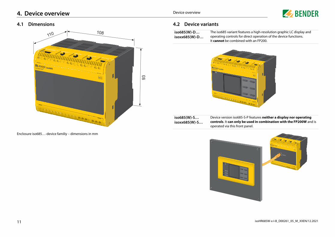
o685 variant features a high-resolution graphic LC display and ting controls for direct operation of the device functions. not be combined with an FP200.
e version iso685-S-P features neither a display nor operating ols. It can only be used in combination with the FP200W and is ted via this front panel.
11
Device overview. Device overview
.1 Dimensions
closure iso685…-device familiy – dimensions in mm
93
108 110
4.2 Device variantsiso685(W)-D…isoxx685(W)-D…
The isoperaIt can
iso685(W)-S…isoxx685(W)-S…
Deviccontropera
D
isoHR685W-x-I-B_D00261_05_M_XXEN/12.20211
4T er supply voltage Us
stem to be monitoredstem to be monitoredstem to be monitored
5050505050505050505050
nect the FP200(W) *rface for Bender products
RearF
rface (see „Connection of the X1 interface“)
resistor for termination of the RS-485 interfacey 1y 2
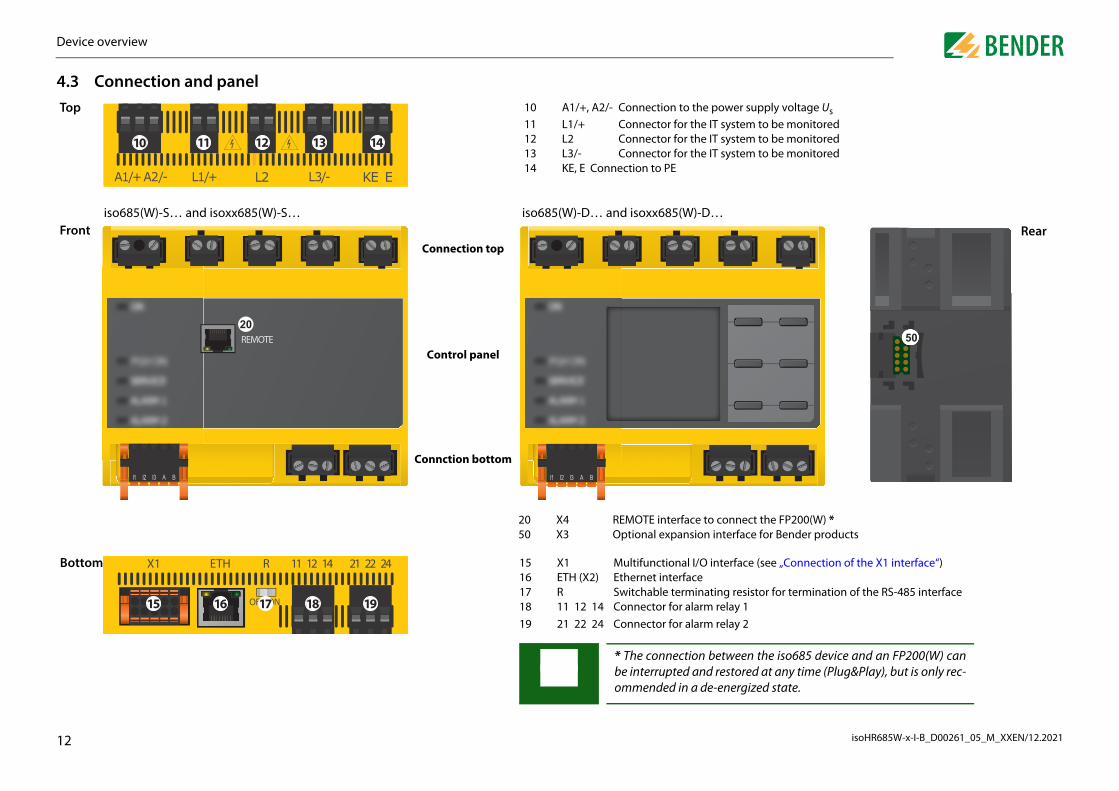
een the iso685 device and an FP200(W) cantored at any time (Plug&Play), but is only rec-ergized state.
B
evice overview
2
.3 Connection and panel
11 12 13 1410
op 10 A1/+, A2/- Connection to the pow11 L1/+ Connector for the IT sy12 L2 Connector for the IT sy13 L3/- Connector for the IT sy14 KE, E Connection to PE
REMOTE20
20 X4 REMOTE interface to con50 X3 Optional expansion inte
ront
Connction bottom
Control panel
Connection top
iso685(W)-S… and isoxx685(W)-S… iso685(W)-D… and isoxx685(W)-D…
242221141211RETHX1
1918171615
15 X1 Multifunctional I/O inte16 ETH (X2) Ethernet interface17 R Switchable terminating18 11 12 14 Connector for alarm rela19 21 22 24 Connector for alarm rela
* The connection betwbe interrupted and resommended in a de-en
ottom
D
isoHR685W-x-I-B_D00261_05_M_XXEN/12.20211
4
4
ettings in the respective menu using the menu buttons. De-, one of the options displayed below is assigned to the but-
es up in a list or increases a value.he device menu. the current process or es one step back in the device menu.larms.es backwards (e.g. to the previous setting step) or parameter.e device self test.
es forwards (e.g. to the next setting step) or parameter.s data and values.es down in a list or reduces a value.nformation.s an action or a selection.
3
Device overviewevice overview
.4 Display elements and device buttons
.4.1 Display elements
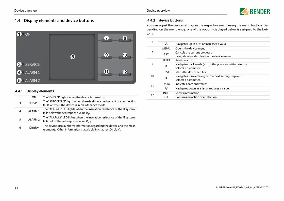
1 ON The "ON" LED lights when the device is turned on.
3 SERVICEThe "SERVICE" LED lights when there is either a device fault or a connection fault, or when the device is in maintenance mode.
4 ALARM 1The "ALARM 1" LED lights when the insulation resistance of the IT system falls below the set response value Ran1.
5 ALARM 2The "ALARM 2" LED lights when the insulation resistance of the IT system falls below the set response value Ran2.
6 DisplayThe device display shows information regarding the device and the meas-urements. Other information is available in chapter „Display“.
1
345
6
7 8
9 10
11 12
4.4.2 device buttonsYou can adjust the device spending on the menu entrytons.
7Navigat
8MENU Opens t
ESCCancelsnavigat
9RESET Resets a
Navigatselects a
10TEST Starts th
Navigatselects a
11DATA Indicate
Navigat
12INFO Shows iOK Confirm

D
isoHR685W-x-I-B_D00261_05_M_XXEN/12.20211
4
4
4
4.5.3 Parameter selection and value adjustment
A"M
UPm
Afo
UfrvCE
Uraecfiin
(backward) r from the dis-acter, use the position.
as been en-tons to select r to be deleted the and
th "OK". Exit ing "ESC".
Ethernet x.3.2
192.
ghijklmnopqrstuvwxyz-.0123456789abcdef
4
Date x.6.4
28.07.2016
Min.Max.
112
se the and buttons to select a pa-meter. The present parameter is indicat-
d by the symbols. Values can be hanged using the and buttons. Con-rm input text by pressing "OK". Exit text put by pressing "ESC".
Device overviewevice overview
.5 Operating and navigating
.5.1 Menu selection
.5.2 List selection
ctivate the menu by pressing the ENU" button
IT system
230 kΩ
OK
R(an) 100kΩ/20kΩ
Commissioning x.6
2/1x
Please set the current
date and time.
se the button to select menu items. ress "ESC" to return form the respective enu level.
n overview of the device menu can be und in chapter .
se the buttons and to select values om a predefined list (menu). The present alue is indicated by a black menu item. onfirm the value with the "OK" button. xit the list selection by pressing "ESC".
System type x.6.6
• DCo ACo 3AC
4.5.4 Character input
Use the (forward) and buttons to select a characteplay. To enter the next char
button to select the next
To delete a character that htered, use the and butthe position of the characteand then select "del" using buttons.
Confirm the entered text withe character input by press

isoHR685W-x-I-B_D00261_05_M_XXEN/12.2021
5
5 s
0 mm
20 mm
20 mm
15
Mounting. Mounting
.1 Common information
Only qualified personnel are permitted to carry out the work necessaryto install, commission and run a device or system.
Read the manual before you begin to mount, connect, and commissionthe unit. Always keep the manual within easy reach for future referencefollowing commissioning.
DANGER
Danger of electrocution due to electric shock!Touching live parts of the system carries the risk of: • A life threatening electric shock • Damage to the electrical installation • Destruction of the deviceBefore installing and connecting the device, make sure that theinstallation has been de-energised. Observe the rules for working onelectrical installations.
5.2 Mounting space
0 mm
M
isoHR685W-x-I-B_D00261_05_M_XXEN/12.20211
51
2
3
D
ng clips delivered with the device (two of them packed using a tool, as illustrated below.
nto the DIN rail.
the DIN rail by pressing the mounting clips until they snap
clipstion of a third mounting clip is only required for "W variants".
108
5418
click!click!ick!
6
imensions in mm
54
Dimensions in mm
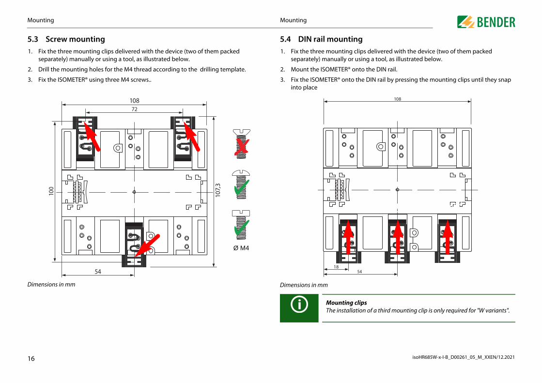
MountingThe installa
Mountingounting
.3 Screw mounting. Fix the three mounting clips delivered with the device (two of them packed
separately) manually or using a tool, as illustrated below.
. Drill the mounting holes for the M4 thread according to the drilling template.
. Fix the ISOMETER® using three M4 screws..
108
107,
3
100
72
Ø M4
5.4 DIN rail mounti1. Fix the three mounting
separately) manually or
2. Mount the ISOMETER® o
3. Fix the ISOMETER® ontointo place
cl

isoHR685W-x-I-B_D00261_05_M_XXEN/12.2021
6
6
cuits when terminals "L1/+", "L2" und "L3/-" are coupled to the IT system to
e protection!to DIN VDE 0100-430, line protection shall be provided for theage.ury from sharp-edged terminals!rations.
enclosure and the terminals with due care.connection from the IT system!
lation or voltage tests are to be carried out, the device must bem the system for the test period. Otherwise the device may be
amage due to improper installation! that only one insulation monitoring device is connected in
ctively connected system. If several devices are connected, thes not work and does not signal insulation faults. This can da-nstallation.currents can result in property damage and injury. Therefore,ly any load current to the terminals. The connecting lines "L1//-" to the system to be monitored must be designed as spur li-
onnect the device as illustrated in the manual leads to deviatingata and function restrictions.
per connection!mmissioning the installation, check that the device has beennnected and check the device functions. Perform a functionaln earth fault via a suitable resistance.easurement errors!
onitored AC system contains galvanically coupled DC circuits,ng applies: An insulation fault can only be detected correctlyectifier valves carry a minimum current of > 10 mA.
lications:C copper lines only!CSA applications, the supply voltage must be protected via 5 A
17
WARNING be monitored can be omitted if the wiring is designed in such a mannerthat the risk of a short circuit is reduced to a minimum. Ensure short-cir-cuit-proof and earth-fault-proof wiring.
For UL appUse 60/75 °For UL and fuses.
Connection. Connection
.1 Connection conditions
In accordance with VDE 0100, only qualified personnel are permitted tocarry out the work necessary to install, commission and run a device orsystem.
DANGER
Risk of electrocution due to electric shock!Touching live parts of the system carries the risk of: • A fatal electric shock • Damage to the electrical installation • Destruction of the deviceBefore installing and connecting the device, make sure that the ins-tallation has been de-energised. Observe the rules for working on elec-trical installations.
DANGER
Risk of electric shock!High voltages may be present at terminals "L1/+" to "L3/-". Direct contactwith these will likely result in electrocution. • Therefore, the device is only to be operated with mounted and locked
terminal covers.• If the device is connected to a live IT system via terminals "L1/+", "L2",
"L3/-", do not disconnect terminals "KE" and "E" from the protective conductor ("PE").
• Connect terminals "KE" and "E" individually to the protective earth con-ductor "PE".
Injury, fire and damage to property due to a short circuit! According to DIN VDE 0100-430, devices used to protect against short cir-
CAUTION
Provide linAccording supply voltRisk of injRisk of laceTouch the Ensure disWhen insuisolated frodamaged.Property dMake sureeach condudevice doemage the iHigh load do not app+", "L2", "L3nes. Failure to ctechnical d
Check proPrior to coproperly cotest using aPrevent mWhen a mthe followiwhen the r

C
isoHR685W-x-I-B_D00261_05_M_XXEN/12.20211
6
6
DC system
he supply voltage
with a nominal system voltage of more than 690 V and withe category III, a fuse for the connection to the system to be mo-st be provided. * 2 A fuses recommended.
CAUTION
o property due to faulty connection! may be damaged if it is simultaneously connected to the sup- via the "X1" interface and via "A1/+" and "A2/-".
Do not connect the device simultaneously via "A1/+", "A2/-" and "X1" topply voltage sources.
L−
L+
* Un > 690 V => F 2A
* *
EKEL3/-L1/+
Fback-up
8
US
EKEL3/-L1/+A2/–A1/+
Fback-upFback-up
different su
Connectiononnection
.2 Connection to a 3(N)AC system
.3 Connection to an AC system
US
Un
L3
N
L2
L1
EKEL3/-L2L1/+A2/–A1/+
Fback-upFback-up
Un L2
L1
L2
L1
6.4 Connection to a
6.5 Connection to t
In systemsovervoltagnitored mu
Damage tThe deviceply voltage
US
Un
A2/–A1/+
Fback-up

C
isoHR685W-x-I-B_D00261_05_M_XXEN/12.20211
he X1 interface
B
RS-485
I1 I2 A BI3
Q1 Q2 M++
low active
V
AVoltagemeter
Currentmeter
passive adjustable
active adjustable
SET
DeactivateDevice
+24 V
Configurable digital inputs (e.g. test, reset, …)Serial interface RS-485, termination by means of a DIP switch R.Supply voltage of the inputs and outputs I, Q and M.Electrical overload protection. Automatic shutdown in the event of short circuits and transients (resettable).When supplied via an external 24 V source, A1/+, A2/- must not be connected.Configurable digital output
Configurable analogue output (e.g. measuring instrument)
Reference potential ground
9
M+ (X1)
(X1)
Connectiononnection
Voltage supply via external power supply unitsIn case of external supply (24 V) the device can be supplied via "A1+"/"A2"– OR via "X1". In case of supply via "A1+"/"A2", make sure that +24 V areapplied to "A1/+" and that "A2/-" is connected to "GND" (ground).Back-up fuse voltage supplyIf the device is supplied via an external power supply unit, the back-up fu-se Fback-up at the connections "A1/+ A2/-" must be selected so that the fee-ding power supply unit is able to trip the DC-compatible back-up fuse.Example: A back-up fuse of 650 mA/T is recommended when using a 24-Vpower supply unit (min. 1 A).Emission requirements for external voltage supply External power supply units that supply the ISOMETER® via "X1" mustmeet the immunity and emission requirements of the relevant applicationstandard. Connection cables longer than 1 m must be shielded.
A1/+ A2/- L1/+ L2 L3/- KE E
US
A2/–A1/+
Fback-upFback-up
6.6 Connection to t
I1 I2 I3 A
X1
high active
X1
TEST RE
I1…I3 (X1)
A, B (X1)
+ (X1)
Q1, Q2 (X1)

C
isoHR685W-x-I-B_D00261_05_M_XXEN/12.20212
6
Cin
6
R
R
to the recesses provided in the enclosure until they click into
click!
click!
0
Connectiononnection
.7 Connection to the Ethernet interface ETH
onnection with standard patch cable (RJ45/no crossover cable) to other ISOMETER®s or terconnection of several ISOMETER®s in STAR topology via a switch.
.8 Connection of the relay interfaces 1 and 2
elay 1 11 common contact12 N/C contacts
14 N/O contacts
elay 2 21 common contact22 N/C contacts
24 N/O contacts
RJ45
141211 242221
6.9 Terminal coversInsert the terminal covers inplace.
click!
click!

isoHR685W-x-I-B_D00261_05_M_XXEN/12.2021
mmissioning7
71
2
3
Afite
C
Initial commissioning
low the instructions of the commissioning wizard on the display.
.1 Setting language language selected here will be used in the menu and for device messages.
.2 Setting date and timerm messages in the history memory and the insulation resistance value over time can y be assigned correctly to the isoGraph when date and time are set correctly.
Check network function!When the device has been integrated into a network, the influence on thenetwork has to be checked with the device switched on and off.
Language x.6.2
• Deutscho Englisho ...
Date x.6.4
28.07.2016
Min.Max.
112
ommissioning x.6
2/1x
lease set the current
date and time.
21
3. Connect the mains voltage4. Run through commissioning wizard5. The ISOMETER® performs a self tes6. Execute a function test with a suitable resistance between the system and earth. 7. Remove the resistance 8. Adjust the basic settings if necessary9. The ISOMETER® is properly connected and functions reliably
Co. Commissioning
.1 General initial commissioning process. Check that the ISOMETER® is properly connected to the system to be monitored.
. Connect the supply voltage to the ISOMETER®. Adjust the device using the commis-sioning wizard. Afterwards, the ISOMETER® performs a self test in four steps. The alarm relays are not checked during this test. After completion of the test, the meas-ured insulation resistance is shown on the display. If the value exceeds the response values indicated in the bottom line of the display, the message "OK" will additionally be displayed.
. Check the ISOMETER® in the system being monitored, e.g. using a suitable resistance to earth
fter setting the response value Ran2 for alarm 2, the device starts a self test, makes the rst measurement and outputs the measured insulation resistance values of the IT sys-m being monitored, then commissioning is completed.
ommissioning pocedure - iso685-x(-B)
For customer-specific configured devices, the commissioning wizardmight be deactivated and cannot be run. In this case, the device is preset.However, the commissioning wizard can be started as described at „Reco-missioning“ .
Observe device status!The device is in an alarm state until initial commissioning has been com-pleted.
Step ISOMETER® commissioning1. Connect the device according to the wiring diagram and device documentation2. Connect the supply voltage
7.2
Fol
7.2The
7.2Alaonl
C
P
C
isoHR685W-x-I-B_D00261_05_M_XXEN/12.20212
7Bthm
7Anrep
7Into„T
e value Ran1 for alarm 1g response value here. A value of 300 Ω/V is recommended for
e value Ran2 for alarm 2g response value here. A value of 100 Ω/V is recommended for
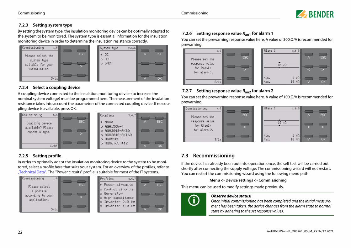
ingeen put into operation once, the self test will be carried out e supply voltage. The commissioning wizard will not restart.
You can restart the commissioning wizard using the following menu path:
-> Device settings -> Commissioning
to modify settings made previously.
rve device status! initial commissioning has been completed and the initial measure- has been taken, the device changes from the alarm state to normal by adhering to the set response values.
Alarm 1 x.6.8
40 kΩ
Min.Max.
1 kΩ10 MΩ
Alarm 1 x.6.9
10 kΩ
Min.Max.
1 kΩ10 MΩ
2
Profiles x.6.7
• Power circuitso Control circuitso Generatoro High capacitance o Inverter >10 Hzo Inverter <10 Hz
Commissioning x.6
5/1x
Please selecta profile
according to yourapplication.
Menu
This menu can be used
ObseOncementstate
Commissioningommissioning
.2.3 Setting system typey setting the system type, the insulation monitoring device can be optimally adapted to e system to be monitored. The system type is essential information for the insulation onitoring device in order to determine the insulation resistance correctly.
.2.4 Select a coupling device coupling device connected to the insulation monitoring device (to increase the ominal system voltage) must be programmed here. The measurement of the insulation sistance takes into account the parameters of the connected coupling device. If no cou-
ling device is available, press OK.
.2.5 Setting profile order to optimally adapt the insulation monitoring device to the system to be moni-red, select a profile here that suits your system. For an overview of the profiles, refer to echnical Data“. The "Power circuits" profile is suitable for most of the IT systems.
Commissioning x.6
5/1x
Please select thesystem type
suitable for yourinstallation.
System type x.6.6
• DCo ACo 3AC
Coupling 5.6.7
• Noneo AGH150W-4o AGH204S-AK80o AGH204S-AK160o AGH520So AGH676S-412
Comissioning 5.6
6/10
Coupling deviceavailable? Pleasechoose a type.
7.2.6 Setting responsYou can set the prewarninprewarning.
7.2.7 Setting responsYou can set the prewarninprewarning.
7.3 RecommissionIf the device has already bshortly after connecting th
x.6
8/1x
Please set theresponse valuefor R(an1)
for alarm 1.
Commissioning x.6
9/1x
Please set theresponse valuefor R(an2)
for alarm 2.

C
isoHR685W-x-I-B_D00261_05_M_XXEN/12.20212
7Y
1
2
3
3
Commissioningommissioning
.4 Configuring password protection for the ISOMETER® iso685ou can assign a password in the device menu.
. Select Menu -> Device settings -> Password in the device menu.
. Enable password protection at Menu -> Device settings -> Passwor -> Status by selecting "On".
. Set a four-digit password at Menu -> Device settings -> Password -> Password . You can use the digits 0 to 9.
Password x.5.1
0000
Min.Max.
09
Password x.5
1. Password ****2. Status off

isoHR685W-x-I-B_D00261_05_M_XXEN/12.2021
8
8Dre
Ine
ctive)y .
y turns orange and displays the fault message.
ult, the LEDs "ALARM 1", "ALARM 2" or "SERVICE" are activat-
resistance has been detected. Since the values Ran1=100 kΩ low the set response value, „ALARM 1“ and „ALARM 2“ have
e appeared, you can navigate through the faults using the
in a DC system or a DC offset is detected in an AC system, ad-n regarding the DC offset will be displayed.
1/4
kΩ kΩ
on fault
24
Display. Display
.1 Standard displayuring normal operation, the ISOMETER® displays the message "OK" and below, the cur-ntly measured insulation resistance.
the bottom line of the display, the set response values for "R(an)" are indicated. In the xample below, Ran1=100 kΩ und Ran2=20 kΩ.
The signal quality of the measurement suits the selected profile.The better the signal quality, the faster and more exact the device can measure.
The signal quality of the measurement does not suit the selected profile. Select a different measurement profile.
Update period between the measuring pulses.
IT system
2 GΩ
OK
R(an) 40kΩ/10kΩ
8.2 Fault display (aAn active fault is displayed bThe upper part of the displa
Depending on the type of faed.
In the following example, aand Ran2=20 kΩ are both bebeen triggered.
If several fault messages havand buttons.
If the value falls below Ran1 ditional detailed informatio
77
Insulati

D
isoHR685W-x-I-B_D00261_05_M_XXEN/12.20212
8Aw
Tb
Ifase
7 3 Fault disappeared
a fault messagee fault message and return to the ISOMETER®'s standard dis-owledged by means of the "RESET" button.
ges can only be reset when the cause of the fault has been
en and "OK" to clear the fault memory. The ISOMETER® re-y.
and device errors are stored in the history memory with date y memory is deleted, the minimum insulation resistance Rmin -isoGraph at Menu -> Data Measured values -> Reset Data-
RESET4 3
21
Keypad1 Press „RESET“-button2 Select RESET by pressing 3 Press the "OK" button to confirm the deletionDisplay4 Functions
presentes? ges are in the ory.
8/8
14 17:0214 17:18
15kΩ
7 3
21
5
Keypad1 Next message2 Exit view3 Previous messageDisplay4 Fault description 5 Alarm value6 Fault appeared/ Fault disappeared7 Number of the selected fault/ Fault message count
n fault
x.1
5
2/4 7 Number of the selected fault/ Fault message count 28.03.
28.03.6
Displayisplay
.3 Fault display (inactive)n inactive fault is indicated by . If several faults have occurred, the number of faults ill also be indicated.
he message shown on the display below means that there has been a fault in the past ut the device is no longer in fault condition.
several fault messages have appeared, you can navigate through the faults using the nd buttons. In addition to the type of fault and the associated alarm value, you can e when the fault has occurred and for how long it has been active.
1/4
3x
8
7
6
5
43
21Keypad1 Next fault message2 MENU selection3 Acknowledge fault4 Perform test measurement5 Previous fault messageDisplay6 Number of faults that have occurred7 Signal quality & measuring pulses8 Number of the selected fault/ Fault message count
IT system
2 GΩ
28.03.14 17:0228.03.14 17:18
7 kΩ7 kΩ
6
5
4 21Keypad1 Next fault message2 Exit view3 Previous fault messageDisplay4 Fault description 5 Alarm value6 Fault appeared/
Insulation fault
8.4 AcknowledgingIn order to acknowledge thplay, all faults must be ackn
This means that fault messaeliminated.
Press the "RESET" button, thturns to the standard displa
8.5 History memoryUp to 1023 alarm messagesand time stamp. If the historwill also be reset in the DataisoGraph.
RESET
Cancel
Delete messag
All messastored
hist
4History
Insulatio
D
isoHR685W-x-I-B_D00261_05_M_XXEN/12.20212
8Ttih
Ttog
8D
Am
settings.
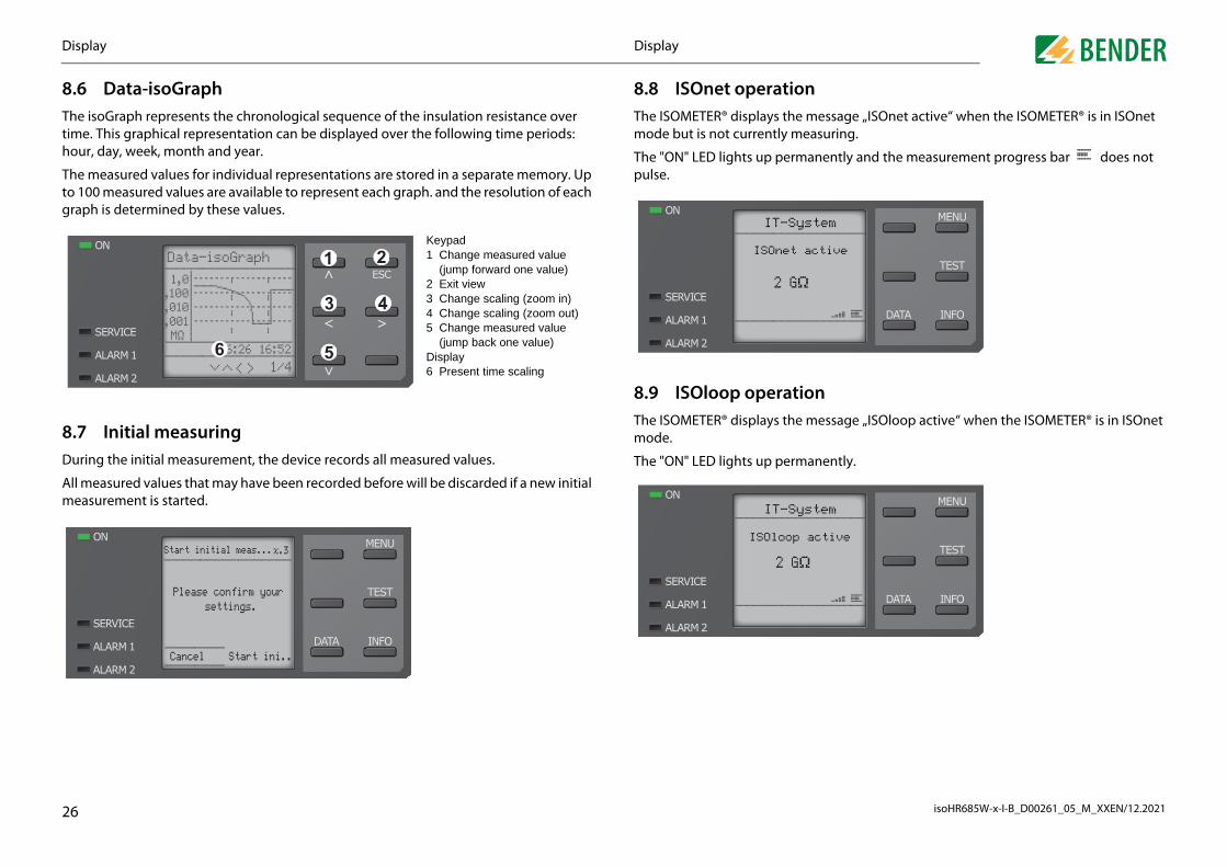
n message „ISOnet active“ when the ISOMETER® is in ISOnet easuring.
anently and the measurement progress bar does not
ion message „ISOloop active“ when the ISOMETER® is in ISOnet
anently.
active
stem
stem
active
Ω
6
Cancel Start ini..
Displayisplay
.6 Data-isoGraphhe isoGraph represents the chronological sequence of the insulation resistance over me. This graphical representation can be displayed over the following time periods: our, day, week, month and year.
he measured values for individual representations are stored in a separate memory. Up 100 measured values are available to represent each graph. and the resolution of each
raph is determined by these values.
.7 Initial measuringuring the initial measurement, the device records all measured values.
ll measured values that may have been recorded before will be discarded if a new initial easurement is started.
1/4
,001,010,100 1,0
MΩ 16:26 16:52
Data-isoGraph
6 5
43
21Keypad1 Change measured value (jump forward one value)2 Exit view3 Change scaling (zoom in)4 Change scaling (zoom out)5 Change measured value (jump back one value)Display 6 Present time scaling
Start initial meas...x.3
Please confirm your
8.8 ISOnet operatioThe ISOMETER® displays themode but is not currently m
The "ON" LED lights up permpulse.
8.9 ISOloop operatThe ISOMETER® displays themode.
The "ON" LED lights up perm
ISOnet
IT-Sy
2 GΩ
IT-Sy
ISOloop
2 G
D
isoHR685W-x-I-B_D00261_05_M_XXEN/12.20212
8Ifp
FITm
Tis
7
Displayisplay
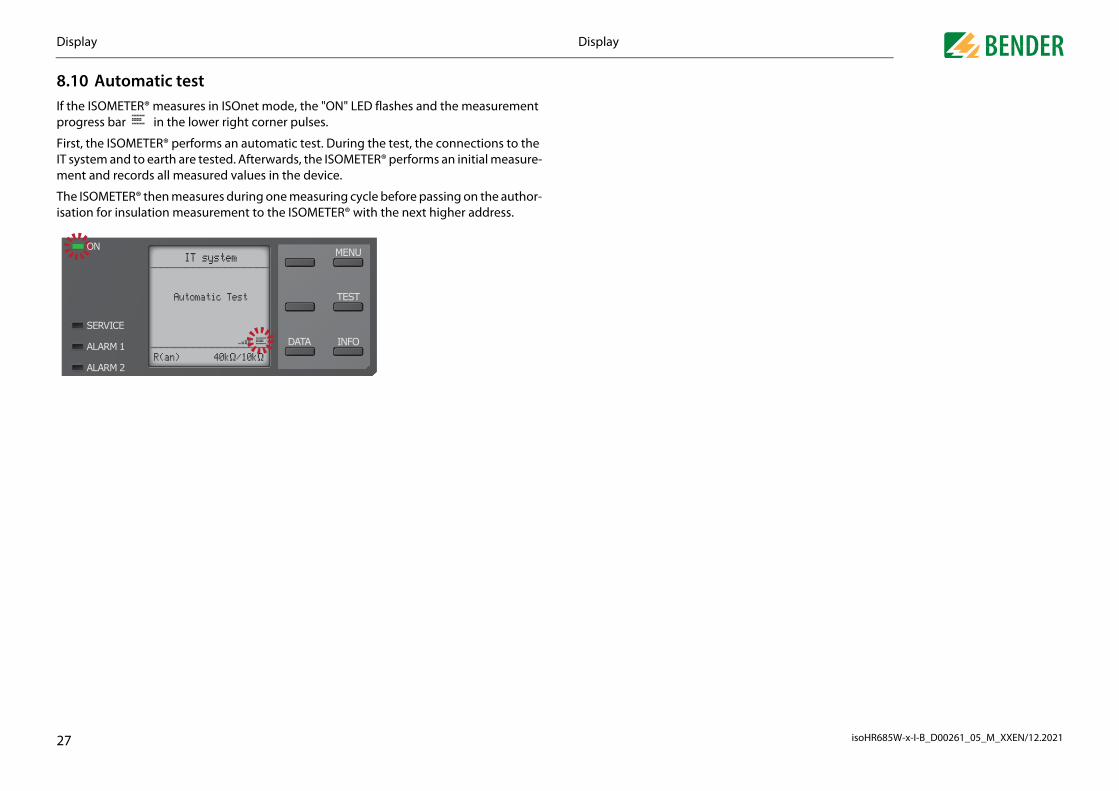
.10 Automatic test the ISOMETER® measures in ISOnet mode, the "ON" LED flashes and the measurement rogress bar in the lower right corner pulses.
irst, the ISOMETER® performs an automatic test. During the test, the connections to the system and to earth are tested. Afterwards, the ISOMETER® performs an initial measure-ent and records all measured values in the device.
he ISOMETER® then measures during one measuring cycle before passing on the author-ation for insulation measurement to the ISOMETER® with the next higher address.
Automatic Test
IT system
R(an) 40kΩ/10kΩ

isoHR685W-x-I-B_D00261_05_M_XXEN/12.2021
9
9
s coloured REDting password protection, access to the menu items coloured
possible after entering a password.
1. TEST2. Reset3. Start initial measuring4. Device:5. ISOnet priority
1. History2. Delete
1. Language2. Clock 1. Time
2. Format3. Summer time4. Date5. Format6. NTP7. NTP Server8. UTC
3. Interface 1. Write access2. Ethernet 1. DHCP
2. IP3. SN4. Std. GW5. DNS Server6. Domain
3. BCOM 1. System name2. Subsystem3. Device address4. Timeout5. TTL for subscription
4. Modbus TCP 1. Port 502
5. RS485 1. Modus2. BS-Bus3. isoData 1.
4. Modbus RTU 1.2.3.4.
4. Display 1. Brightness2. Autom.dimming
5. Password 1. Password2. Status
6. Commissioning7. Backup 1. Save
2. Restore
8. Approve9. Factory setting10. Software 1. Update via interface
2. UPDATE
11. Service*
* = Service PW needed
28
4. Digital 2 1. Test2. Relay mode3. Function 14. Function 25. Function 3
5. Buzzer 1. Test2. Function 13. Function 24. Function 3
6. Analogue 1. Mode2. Midscale3. TEST4. Function
Menu itemAfter activaRED is only
6. Info
Settings. Settings
.1 Menustructure1. Alarm settings 1. Insulation alarm 1. Alarm 1
2. Alarm 23. Memory
2. DC Alarm 1. Alarm2. U(DC-E)
3. Profile4. System type5. Coupling6. ISOnet 1. ISOnet
2. Number of devices
7. ISOloop 1. ISOloop2. Number of devices
8. isoSync9. t(start)10. Coupling monitoring11. Behaviour when inactive 1. Initial value
2. Keep state
12. Inputs 1. Digital 1 1. Mode2. t(on)3. t(off)4. Function
2. Digital 2 1. Mode2. t(on)3. t(off)4. Function
3. Digital 3 1. Mode2. t(on)3. t(off)4. Function
13. Outupts 1. Relay 1 1. Test2. Relay mode3. Function 14. Function 25. Function 3
2. Relay 2 1. Test2. Relay mode3. Function 14. Function 25. Function 3
3. Digital 1 1. Test2. Relay mode3. Function 14. Function 25. Function 3
2. Data meas. values
3. Control
4. History
5. Device settings

S
isoHR685W-x-I-B_D00261_05_M_XXEN/12.20212
9
9
Tindti
9
Inc
A"A
Ais
9
Fo
9
Fo
aktiv aktiv inaktiv inaktiv
ory
faults at the outputs relay 1, relay 2, digital output 1, digital
the event of a DC offset voltage (UDC-E) in the system.
between 20 V and 1 kV.
fault becomes inactive, the programmed outputs remain in fault dition until the system has been reset manually.
fault becomes inactive, the programmed outputs automatically nge the state.
DC alarm is triggered in the event of a DC offset voltage. DC alarm is NOT triggered in the event of a DC offset voltage.
t
DC+
DC-
200 V
RfU1
U1
U2
U2
UDC-E=(U1+U2)/2=(120 V-80 V)/2=20 V
UDC-E
9
.2 (1.1.1) Alarm 1
or "Alarm 1" an insulation resistance of 1 kΩ…3 GΩ can be set independently f "Alarm 2".
.2 (1.1.2) Alarm 2
or "Alarm 2" an insulation resistance of 1 kΩ…3 GΩ can be set independently f "Alarm 1".
Settingsettings
.2 Settings in the device menu
.2 (1.0) Alarm settings
he limit values for the insulation resistances of "Alarm 1" and "Alarm 2" can be specified the alarm settings menu and can be adapted to the user profile of the ISOMETER®. A
evice password is required for entering the settings. You can adjust the following func-ons:
.2 (1.1) Insulation alarm
the "Insulation alarm" menu, the ISOMETER® limit values for "Alarm 1" and "Alarm 2" an be set.
ctivation or deactivation of the two alarm levels Ran1 for "Alarm 1" and Ran2 for larm 2" are illustrated in the graphic below.
n alarm will become inactive as soon as the hysteresis of the set operating value exceeded.
Representation of the menu items in the headings The settings of the ISOMETER® are explained in the order of the devicemenu. The menu items shown in the device display are indicated in brack-ets in the headings of this chapter.
t
R
Ran1
Ran2
Alarm 1 Alarm 2 Alarm 2
Hysterese
Alarm 1
Hysterese
9.2 (1.1.3) Fault mem
Automatic reset of inactive output 2:
9.2 (1.2) DC alarm
The DC alarm is triggered in
9.2 (1.2.1) Alarm
9.2 (1.2.2) U(DC-E)
Set the DC alarm to a value
•on If acon
•off If acha
•on The•off The
120 V
U
100 V
0 V
-80 V
-100 V
Rf

S
isoHR685W-x-I-B_D00261_05_M_XXEN/12.20213
9
Ao
T
9
A
9
AaY
9
M
Tin
Fti
•
•
•
•
•
•
•
•
•
•
•
•
•
•
•AGH520S
•
ONet function
devices
vices (2…20) in a subsystem.
nktion aktiv oder inaktiv:
.
value subscription
ubscription and the ISOloop function are activated, the mea-easuring device are distributed within the team and shown
e coupled systems
ated with a start-up delay of 0…600 seconds. The start-up is surement takes place.
9.2 (1.10) Coupling monitoring
ly monitors the coupling of energised systems. The coupling onitored at 8-hour intervals. This monitoring function can be
e ISOnet is deactivatede ISOnet function is activated via BCOM
on:
chronisation is enabledchronisation is disabled.
pling monitoring is activated.pling monitoring is deactivated.
0
.2 (1.6) ISOnet
ake the settings to use the ISONet function.
he ISOnet function ensures via the Ethernet connection that only one ISOMETER® of the terconnection is active when several ISOMETER®s are connected to an IT system.
or further information regarding the ISOnet function, refer to the chapter „Special func-ons for couppled IT systems“.
AGH676S-4The ISOMETER® continuousof de-energised systems is mactivated or deactivated.
•on Cou•off Cou
Settingsettings
.2 (1.3) Profile
dapt the area of application of the ISOMETER® to your system profile. For a description f the profiles, refer to chapter „Technical data“.
he following can be selected:
.2 (1.4) System type
dapt the ISOMETER® to the IT system to be monitored. The following can be selected:
.2 (1.5) Coupling
dapt the ISOMETER® to the requirements of Bender coupling devices. For a description bout the connection of coupling devices refer to chapter “Coupling devices” . ou may select.
Power circuits Suitable for most IT systems. Control circuits Not recommended for voltages > 230 V. Generator Fast measuring times, fast fault location possible.High capacitance Suitable for systems with high system leakage capacitances.Inverter > 10 Hz Suitable for systems with dynamic frequency control by inverters
in the range 10…460 Hz.Inverter < 10 Hz Suitable for systems with extremely low frequency controls in the
range 0.1…460 Hz.Customer-specific Enables the Bender service to make customer-specific settings.
DC DC systemAC Single-phase AC system 3AC 3AC system
none
AGH150W
AGH204S-AK80
AGH204S-AK160
9.2 (1.6.1) ISOnet
Activate or deactivate the IS
9.2 (1.6.2) Number of
Configure the number of de
9.2 (1.7) ISOloopSchalten Sie die ISOloop-Fu
9.2 (1.7.1) ISOloopTurns the function on or off
9.2 (1.7.2) Measured
When the measured value ssured values of the active mon all displays.
9.2 (1.8) ISOsync
Synchronisation in capacitiv
9.2 (1.9) (Start)
The ISOMETER® can be operdelayed until the initial mea
•off Th•BCOM Th
1. ISOloop:
2. Measured value subscripti
•on Syn•off Syn

S
isoHR685W-x-I-B_D00261_05_M_XXEN/12.20213
9
T
T
9
P
9
T
•
•
t
r a switch-on signal can be set between 100 ms and 300 s.
r a switch-off signal can be set between 100 ms and 300 s.
tion of the digital inputs of the ISOMETER® can be set differ-
.
.
otal of six outputs. an be set for the outputs:
an be set for each relay:
ital input without functionvice self testet of fault and alarm messages device DOES NOT measure the insulation resistance, the mes-e Device inactive appears on the display. The IT system is T being monitored! The device is isolated from the system via rnal system isolating switches.
his case, all recorded measured values are discarded and a new asurement is started
ion of the ISOMETER® with digital inputs inputs are not interconnected. In order to avoid unintentionaln of the ISOMETER®, it should be ensured during configurationnt functions are assigned to the inputs.
1
Active low An event is carried out on the falling edge of the digital input (high to low).Response time t(on)/t(off) after a switch-off signal.
Ix
X1 X1+
t0
1
t(on)
Reaktion ReaktionImpuls on
< t(on)
The ISOMETER® provides a tThe following parameters c
9.2 (1.12.1) Relay 1
The following parameters c
Settingsettings
.2 (1.11) Inputs
he ISOMETER® provides a total of three digital inputs.
he exemplary wiring diagram shows how the digital inputs can be wired.
.2 (1.11.1) Digital 1
arameters of the digital input.
.2 (1.11.1.1) Mode
he operating mode for the digital input can be set to the following values:
Active high An event is carried out on the rising edge of the digital input (low to high).Response time t(on)/t(off) after a switch-on signal
RS-485
I1 I2 A BI3
Q1 Q2 M++
high active
low active
V
AVoltagemeter
Currentmeter
passive adjustable
X1
active adjustable
TEST RESET
DeactivateDevice
+24 V
Ix
X1 X1+
0
1
t(on)
ReaktionImpuls on
Reaktion
< t(on)
9.2 (1.11.1.2) t(on)
The response time t(on) afte
9.2 (1.11.1.3) t(off)
The response time t(off) afte
9.2 (1.11.1.4) Function
The parameters for the funcently:
9.2 (1.11.2) Digital 2
Refer to “Digital 1”, page 31
9.2 (1.11.3) Digital 3
Refer to “Digital 1”, page 31
9.2 (1.12) Outputs
•off Dig•TEST De•RESET Res•Deactivate device
ThesagNOinte
•Start initial measurement
In tme
DeactivatThe digitaldeactivatiothat differe

S
isoHR685W-x-I-B_D00261_05_M_XXEN/12.20213
9
Tm
9
T
9
Uo
T
•
•
•
•
•
F
•
•
•Ins. alarm 2 The status of the output changes when the value falls below the set
•
2
3) “Function 1” on page 32.
3
3) “Function 1” on page 32.
“Relay 1” on page 31.
atus of the output changes in case of an earth fault in the direction when 75 % of the value are exceeded. This does not concern sym-al faults. This function will only be carried out when the value falls the response value Ran1 and when the nominal system voltage is 0 V.
atus of the output changes in case of an earth fault in the direction when 25 % of the value are exceeded. This does not concern sym-al faults. This function will only be carried out when the value falls the response value Ran1 and when the nominal system voltage is 0 V.
atus of the output changes in the event of a resistance ratio en DC+ and DC- of 25 % to 75 %.
atus of the output changes in the event of an internal device fault.atus of the output changes on the occurrence of any alarm and
essages (Ins. alarm 1 & 2, DC-/DC+ alarm, symmetrical alarm, con-n and device errors).
atus of the output changes at the end of the initial measurement.
atus of the output changes when the device has been deactivated igital input or the "Control" menu.atus of the output changes on the occurrence of a DC offset volt- the system.e of state when one of the following events occurs:et general erroret device timeoutet missing device
oop fault
iption
Symmetrischer Alarm DC- Alarm5 % 50 % 75 % 100 %
2
response value Ran2.
Connection fault The status of the output changes when one of the following connection fault occurs:• No low-resistance connection between the line conductors.• No low-resistance connection between terminals "E" and "KE" to earth.• Load at voltage output too small• Load at voltage output too high• Load on "X1" too high.
9.2 (1.12.1.4) Funktion
Refer to chapter 9.2 (1.12.1.
9.2 (1.12.1.5) Funktion
Refer to chapter 9.2 (1.12.1.
9.2 (1.12.2) Relais 2
Refer to chapter 9.2 (1.12.1)
Settingsettings
.2 (1.12.1.1) TEST
he functional test of the relay can be activated or deactivated. This only applies to the anual test and not to the cyclic device self test:
.2 (1.12.1.2) Relay mode
he relay mode can be adapted to the application:
.2 (1.12.1.3) Function 1
p to three functions can be assigned to one output. The functions are linked to an OR perator:
he following parameters can be set.
on The manual test checks the switching function of the relay. The relays switch for approx. 2 seconds.
off The manual test does not check the switching function of the relay
N/C Normally closed - N/C operation contacts 11-12-14 / 21-22-24 (in fault-free condition, the alarm relay is energised).
N/O Normally open - N/O operation contacts 11-12-14 / 21-22-24 (in fault-free condition, the alarm relay is de-energised).
Flash Relay flashs. Flashrate: 1 s ON / 1 s OFF
unction Description
off The function is not used.Ins. alarm 1 The status of the output changes when the value falls below the set
response value Ran1.
≥ 1 Reaktion
Funktion 1
Funktion 2
Funktion 3
•DC- alarm The stof DC metricbelowUn ≥ 5
•DC+ alarm The stof DC+metricbelowUn ≥ 5
•Symmetrical alarm
The stbetwe
•Device fault The st•Common alarm The st
fault mnectio
•Measurement com-plete
The st
•Device inactive The stvia a d
•DC offset alarm The stage in
•Connection error Chang• ISOn• ISOn• ISOn• ISOl
Function Descr
DC+ Alarm0 % 2

S
isoHR685W-x-I-B_D00261_05_M_XXEN/12.20213
9
T
9
Tto
9
T
9
R
•
•
•
•
“Function 1” on page 32.
“Function 1” on page 32.
Digital 1” on page 33.
be set for the buzzer.
zer can be activated or deactivated. This only applies to the clic device self test:
“Function 1” on page 32.
“Function 1” on page 32.
“Function 1” on page 32.
be set for the analogue output.
et for the operating mode of the analogue output:
anual test activates the buzzer sound.anual test does not activate the buzzer sound.
missible load ≤ 600 Ωmissible load ≤ 600 Ωmissible load ≤ 4 kΩ
missible load ≥ 1 kΩmissible load ≥ 1 kΩ
X1A
X1
V
3
.2 (1.12.3.3) Function 1
efer to chapter 9.2 (1.12.1.3) “Function 1” on page 32.
Maximalen Ausgangsstrom beachten!Maximaler Ausgangsstrom bei interner Spannungsversorgungüber A1/+ und A2/-: 200 mA in Summe an X1.Beachten Sie außerdem die Formel zur Berechnung von ILmaxX1 in denTechnischen Daten.
Current output
•0-20 mA Per•4-20 mA Per•0-400 μA Per
Voltage output
•0-10 V Per•2-10 V Per
M+
X1
M+
X1
Settingsettings
.2 (1.12.3) Digital 1
he following parameters can be set for each of the digital outputs:
.2 (1.12.3.1) TEST
he functional test of the digital output can be activated or deactivated. This only applies the manual test and not to the cyclic device self test:
.2 (1.12.3.2) Mode
he following settings can be used to set the operating mode for the digital output:
on The manual test changes the status of the digital output.off The manual test does not change the status of the digital output.
Active In active mode, +24 V are applied internally to output Qx.
Passive In passive mode, ≤ 32 V are connected externally (see technical data). The output switches the applied potential to ground.
X1
iso6
85 Qx
+
X1
iso6
85 Qx
+
or
X1
iso6
85 Qx
+
X1
iso6
85 Qx
+
intern extern
or
9.2 (1.12.3.4) Function 2
Refer to chapter 9.2 (1.12.1.3)
9.2 (1.12.3.5) Function 3
Refer to chapter 9.2 (1.12.1.3)
9.2 (1.12.4) Digital 2
Refer to chapter 9.2 (1.12.3) “
9.2 (1.12.5) Buzzer
The following parameters can
9.2 (1.12.5.1) TEST
The functional test of the buzmanual test and not to the cy
9.2 (1.12.5.2) Function 1
Refer to chapter 9.2 (1.12.1.3)
9.2 (1.12.5.3) Function 2
Refer to chapter 9.2 (1.12.1.3)
9.2 (1.12.5.4) Function 3
Refer to chapter 9.2 (1.12.1.3)
9.2 (1.12.6) Analogue
The following parameters can
9.2 (1.12.6.1) Mode
The following values can be s
•on The m•off The m

S
isoHR685W-x-I-B_D00261_05_M_XXEN/12.20213
9
S
C
9.2 (1.12.6.3) TEST
Tthu
•
••
•
•
g for the analogue output. The following parameters can be
values
in measured values for a specific period of time. You can view s. value" menu. Navigate through the different views using
eration:
pending on the measured insulation value, an analogue current oltage signal is provided at the output.
pending on the measured DC offset, an analogue current or volt- signal is provided at the output. This setting can only be used
en Linear is selected in the "Midscale" menu.
plays the insulation resistance and chronological sequence. Scaling: Hour Scaling: Day Scaling: Week Scaling: Month Scaling: Yearplays the current insulation resistance, the minimum insulation istance measured and the system leakage capacitance.plays the system phase-to-phase voltages and the mains fre-ncy (r.m.s. values)
plays the system phase-to-earth voltages
Symmetrischer Alarm DC- Alarm % 50 % 75 % 100 %
10 V20 mA
400 μA
4
he functional test of the analogue output can be activated or deactivated. In this way, e analogue output is adjusted once for the entire range. This only applies to the man-
al test and not to the cyclic device self test:
on The manual test checks the analogue output function.off The manual test does not check the analogue output function.
9.2 (3.0) Control
Controling of a device in op
1. TEST
2. Reset
3. Start initial measurement
4. EDS
5. Device
6. ISOnet priority
Settingsettings
.2 (1.12.6.2) Midscale
elect the appropriate midscale. The following parameters can be set:
alculation of the insulation resistance using the analogue output:
Linear The switching signal is linear to the insulation resistance in the indi-cated measuring range.
28 kΩ120 kΩ
The switching signal is analogue to the mid scale of 28 kΩ or 120 kΩ on a measuring instrument.
Lower value Analogue Output A10 mA4 mA0 μA0 V2 V
Upper valueAnalogue Output A220 mA20 mA400 μA10 V10 V
100 Ω 1 MΩ
I/U20 mA / 400 μA
10 V
0 mA / 4 mA0 V / 2 V
1 k
1 M
100
100
k Ω
28 kΩ120 kΩ
100 Ω ................100 kΩ1 kΩ ........................................... 1 MΩ
I/U20 mA / 400 μA
10 V
0 mA / 4 mA0 V / 2 V
120 kΩ28 kΩ
RSKM= 28 kΩ or 120 kΩ/Midscale
A3= Measured value analoge output
RF= Insulation fault in kΩ
RF = - RSKM(A2 - A1) * RSKM
A3 - A1
9.2 (1.12.6.4) Function
Select the appropriate settinset.
9.2 (2.0) Data measured
The ISOMETER® stores certathese data in the "Data meathe and buttons:
•Insulation value Deor v
•DC offset Deagewh
1. isoGraph data Dis1.11.21.31.41.5
2. Insulation data Disres
3. IT system data Disque
4. IT system data Dis
DC+ Alarm0 % 250 V/2 V0 mA/4 mA 0 μA

S
isoHR685W-x-I-B_D00261_05_M_XXEN/12.20213
9
S
9
R
9
A
9
S
9In
9
Aati
9
In
9
B
9.2 (5.1) Language
S
9
S
9
S
•
•
•
•
e)
me format to be displayed:
me
ered in the following settings:
ased on the time format.
te)
you want to be displayed:
ike to synchronise the current time via NTP. To use this func- NTP server.
P server.
TC (coordinated world time). For Germany, set +1 for winter-er time (CEST).
hour notation am/pmhour notation
ic change between summer time and standard time.ing Time
ime change according to North American regulation.d Sunday in March from 02:00 a.m. to 03:00 a.m. (local time)nday in November from 03:00 a.m. to 02:00 a.m. (local time)pean Summer Time
ime change according to Central European regulation.unday in March from 02:00 a.m. CET to 03:00 a.m. CEST.nday in October from 03:00 a.m. CEST to 02:00 a.m. CET.
, month, yearnth, day, year
chronisation via NTP server is activated.•off Synchronisation via NTP server is deactivated.
5
electing the display language:
.2 (5.2) Clock
etting the time and date display format.
.2 (5.2.1) Time
etting the time format to 24 hours or 12 hours am/pm.
Deutsch Espanol Norsk Portugues
English (GB) Francais Polski
9.2 (5.2.7) NTP server
Set the IP address of the NT
9.2 (5.2.8) UTC
Set the time according to Utime (CET) and +2 for summ
Settingsettings
.2 (3.1) TEST
tarts a manual device test.
.2 (3.2) Reset
eset of fault and alarm messages.
.2 (3.3) Start initial measurement
ll recorded measurements are discarded and a new measurement is started.
.2 (3.4) EDS
tarts an insulation fault location process on the connected EDS device
.2 (3.5) Device:sulation resistance measurement function of the ISOMETER® active or inactive:
.2 (3.6) ISOnet priority
ssigns priority to a device in ISOnet mode for a period of 12 hours. While the priority is ctive, all other devices in ISOnet mode are inactive. Priority can be withdrawn at any me. After 12 hours, automatic switchover to normal ISOnet operation takes place.
.2 (4.0) History
the history menu, the faults detected by the ISOMETER® are displayed.
.2 (5.0) Device settings
asic settings of the ISOMETER®.
Aktiv The device is active.Inaktiv Display shows message Device inactive. No monitoring of the IT system!
History Overview of faults that have occurred.Delete Reset the history memory.
9.2 (5.2.2) Format (tim
Selecting the appropriate ti
9.2 (5.2.3) Summer ti
Summer time can be consid
9.2 (5.2.4) Date
Entering the current date b
9.2 (5.2.5) Format (da
Select the date format that
9.2 (5.2.6) NTP
Select whether you would ltion you must configure the
•12 h 12-•24 h 24-
•off No automat•DST Daylight Sav
Automatic tStart: SeconEnd: First Su
•CEST Central EuroAutomatic tStart: Last SEnd: Last Su
•dd.mm.yy day•mm-dd-yy mo
•on Syn

S
isoHR685W-x-I-B_D00261_05_M_XXEN/12.20213
9
M
9
Spth
9
SE
9
Sthstis
Y
9.2 (5.3.2.2) IP (manual configuration)
Svy
9
Sn
•
•
1
2
3
4
5
6
•
•
anual configuration)
d in your network, enter its IP address here. If there is no ga- an address not yet used in the address range as gateway add-
cccessed without setting a standard gateway address. nistrator for information on the configuration of your local
er
r the server's IP address. For questions regarding the configu-act your network administrator.
ions regarding the configuration of the domain, contact your
munication with other devices via BCOM.
ame
network in which the devices are located. In order to guaran- to communicate via BCOM, all devices must have the same
m
dress of the network in which the devices are located. The de- subsystems with the same or different subsystem addresses.
dress
h device must have a different address to distinguish it from sure correct communication.
Set the timeout for messages between 100 ms…10 s. This time specification defines the for a device to respond.
bscription
92 min.
ls at which the ISOMETER® sends messages to e.g. a gateway. n alarms or substantial value changes) are always sent
6
et the appropriate IP address for the ISOMETER®. Make sure that the address of the de-ice is within the address range of your network. For information on the address range of our network, contact your network administrator.
.2 (5.3.2.3) SN (manual configuration)
et the appropriate subnet mask. (Standard subnet mask: 255.255.255.0) Contact your etwork administrator for more information.
maximum permissible time
9.2 (5.3.3.5) TTL for su
Set a time between 1 s…10
This time defines the intervaSevere alarms (e.g. insulatioimmediately.
Settingsettings
.2 (5.3) Interface
enu for connecting and parameterising other devices to the ISOMETER.
.2 (5.3.1) Write access
et whether the device can be parameterised externally via Modbus or web server. Dis-laying and reading out data via Modbus and web server is always possible, regardless of is setting.
.2 (5.3.2) Ethernet
et the parameters for communication with other devices via the Ethernet interface. The thernet interface can be used for communication with Modbus, web server and BCOM.
.2 (5.3.2.1) DHCP
elect whether you want to use automatic address assignment via your DHCP server. If e automatic IP address assignment is enabled, the IP address, the subnet mask and the andard gateway will be automatically assigned. If the automatic IP address assignment disabled, these settings must be made manually in the menu.
ou can view the IP address in the "Info" menu.
Allow Allow external parameter setting.Deny Refuse external parameter setting.
. DHCP: Entering a DHCP server
. IP: Entering an IP address
. SN: Entering a subnet mask
. Std.GW: Entering a standard gateway
. DNS: Entering a DNS server
. Domain Entering a domain name
on Automatic IP address assignment is activated.off Automatic IP address assignment is deactivated.
9.2 (5.3.2.4) Std. GW(m
If a standard gateway is useteway in the network, enterress. The device cannot be aContact your network adminetwork.
9.2 (5.3.2.5) DNS serv
If a DNS server is used, enteration of a DNS server, cont
9.2 (5.3.2.6) Domain
Enter the domain. For questnetwork administrator.
9.2 (5.3.3) BCOM
Set the parameters for com
9.2 (5.3.3.1) System n
Set the system name of the tee that all devices are ablesystem name.
9.2 (5.3.3.2) Subsyste
Configure the subsystem advices can communicate with
9.2 (5.3.3.3) Device ad
Assign a device address. Eacothers in the system and en
9.2 (5.3.3.4) Timeout
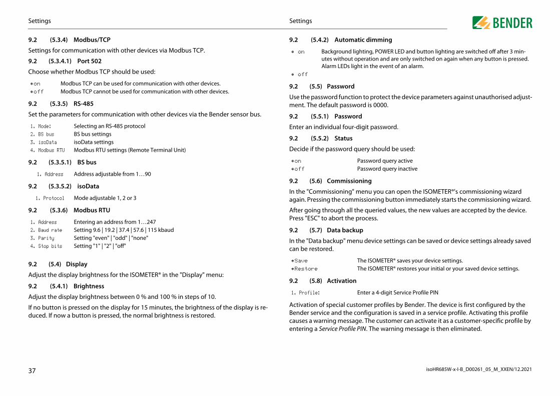
S
isoHR685W-x-I-B_D00261_05_M_XXEN/12.20213
9
S
9
C
9
S
9
9
9
9
A
9
A
Ifd
•
•
1
2
3
4
1
2
3
4
omatic dimming
ord
nction to protect the device parameters against unauthorised adjust-ssword is 0000.
sword
our-digit password.
us
rd query should be used:
issioning
ng" menu you can open the ISOMETER®'s commissioning wizard ommissioning button immediately starts the commissioning wizard.
all the queried values, the new values are accepted by the device. the process.
ackup
menu device settings can be saved or device settings already saved
9.2 (5.8) Activation
er profiles by Bender. The device is first configured by the figuration is saved in a service profile. Activating this profile The customer can activate it as a customer-specific profile by . The warning message is then eliminated.
nd lighting, POWER LED and button lighting are switched off after 3 min-out operation and are only switched on again when any button is pressed.
s light in the event of an alarm.
Password query activePassword query inactive
The ISOMETER® saves your device settings.The ISOMETER® restores your initial or your saved device settings.
er a 4-digit Service Profile PIN
7
.2 (5.4.1) Brightness
djust the display brightness between 0 % and 100 % in steps of 10.
no button is pressed on the display for 15 minutes, the brightness of the display is re-uced. If now a button is pressed, the normal brightness is restored.
Activation of special customBender service and the concauses a warning message. entering a Service Profile PIN
1. Profile: Ent
Settingsettings
.2 (5.3.4) Modbus/TCP
ettings for communication with other devices via Modbus TCP.
.2 (5.3.4.1) Port 502
hoose whether Modbus TCP should be used:
.2 (5.3.5) RS-485
et the parameters for communication with other devices via the Bender sensor bus.
.2 (5.3.5.1) BS bus
.2 (5.3.5.2) isoData
.2 (5.3.6) Modbus RTU
.2 (5.4) Display
djust the display brightness for the ISOMETER® in the "Display" menu:
on Modbus TCP can be used for communication with other devices.off Modbus TCP cannot be used for communication with other devices.
. Mode: Selecting an RS-485 protocol
. BS bus BS bus settings
. isoData isoData settings
. Modbus RTU Modbus RTU settings (Remote Terminal Unit)
1. Address Address adjustable from 1…90
1. Protocol Mode adjustable 1, 2 or 3
. Address Entering an address from 1…247
. Baud rate Setting 9.6 | 19.2 | 37.4 | 57.6 | 115 kbaud
. Parity Setting "even" | "odd" | "none"
. Stop bits Setting "1" | "2" | "off"
9.2 (5.4.2) Aut
9.2 (5.5) Passw
Use the password fument. The default pa
9.2 (5.5.1) Pas
Enter an individual f
9.2 (5.5.2) Stat
Decide if the passwo
9.2 (5.6) Comm
In the "Commissioniagain. Pressing the c
After going throughPress "ESC" to abort
9.2 (5.7) Data b
In the "Data backup"can be restored.
• on Backgrouutes withAlarm LED
• off
•on
•off
•Save
•Restore
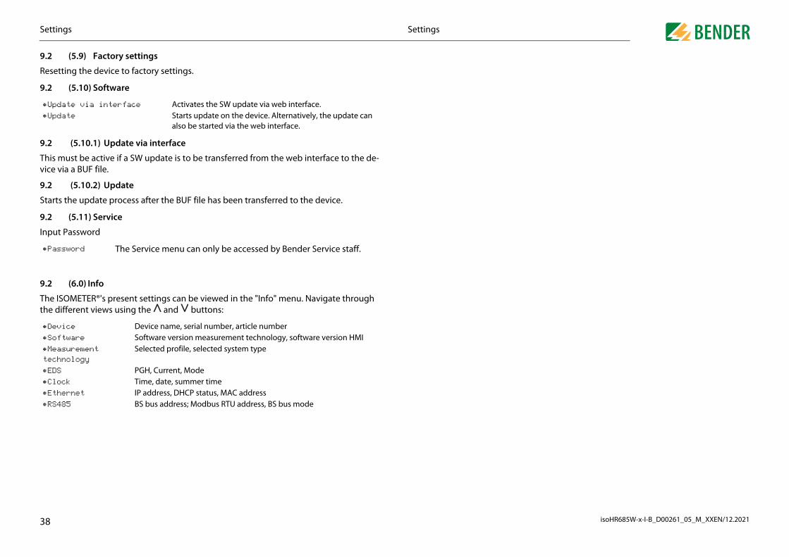
S
isoHR685W-x-I-B_D00261_05_M_XXEN/12.20213
9
R
9
9
Tv
9
S
9
In
9
Tth
•
•
•
•
•
•t
•
•
•Ethernet IP address, DHCP status, MAC address•
8
RS485 BS bus address; Modbus RTU address, BS bus mode
Settingsettings
.2 (5.9) Factory settings
esetting the device to factory settings.
.2 (5.10) Software
.2 (5.10.1) Update via interface
his must be active if a SW update is to be transferred from the web interface to the de-ice via a BUF file.
.2 (5.10.2) Update
tarts the update process after the BUF file has been transferred to the device.
.2 (5.11) Service
put Password
.2 (6.0) Info
he ISOMETER®'s present settings can be viewed in the "Info" menu. Navigate through e different views using the and buttons:
Update via interface Activates the SW update via web interface.Update Starts update on the device. Alternatively, the update can
also be started via the web interface.
Password The Service menu can only be accessed by Bender Service staff.
Device Device name, serial number, article numberSoftware Software version measurement technology, software version HMIMeasurement echnology
Selected profile, selected system type
EDS PGH, Current, ModeClock Time, date, summer time

isoHR685W-x-I-B_D00261_05_M_XXEN/12.2021
1
1TB
1B
Inhre
F w
1M
ADcovw
x685 device family feature an integrated web server which a web browser. This way, measured values of the ISOMETER®s terised.
browsers:
by entering the IP address of the ISOMETER® into the web 92.168.0.5) The current IP address of the respective ISOME-vice menu at "Info" -> "Ethernet"
llowing functions:
ation (e.g. device type, software version, etc.)ce settingsges information of the individual parameterss in uset measured values
raphic representation of the insulation resistance (isoGraph)imple visualisation without any programmingettingast parameterisation of the devicenment and editing options of device textsege of specific events for fast support by the Bender service
ctions of 5 TCP/IP connections can be used simultaneously.
evice may access the web server at a time. If several devices trye web server at the same time, this may result in timeouts.
ss ccess is deactivated by default in the device menu (= Deny). Toet parameters via the web server, the write access must first be
n the device menu (= Allow).
39
service-support/downloads .
In order to be able to parameterise the device externally via Modbus, themenu item "Allow" must have been set in the "Write access" menu.
– Detailed g – Fast and s • Parameter s – Easy and f – Easy assig • Maintenanc – Data stora
Device communication0. Device communication
0.1 Ethernet interfacehe Ethernet interface can be used for communication with Modbus, web server and COM.
0.2 BCOMCOM is intended for communication between Bender devices via Ethernet.
order to guarantee that all devices are able to communicate via BCOM, all devices must ave the same system name. Devices can be organised in subsystems. Each device requi-s an individual device address.
or more information regarding BCOM, refer to the BCOM manual (D00256) at ww.bender.de/en/service-support/downloads .
0.3 Modbus/TCPodbus is an international widely used protocol for data transfer between devices.
ll measured values, messages and parameters are stored in virtual register addresses. ata can be read at a specific register address with a read command. With a write mmand, data can be written to a register address. The register addresses of the indi-
idual measured values und parameters can be found in the manual "iso685–D Annex A" ith the title "ISOMETER® iso685 device family - Modbus settings" at www.bender.de/en/
A maximum of 5 TCP/IP connections can be used simultaneously.
When address 0 has been set for the communication via BCOM the devicecan be accessed via the network (e. g. for parameter setting, etc.) but itcannot communicate with other devices.
10.4 Web serverThe ISOMETER®s of the isoxdisplays the device data via can be read out and parame
Preferably use the following
The web server is accessed browser. (Example: http://1TER® can be found in the de
10.4.1 Conventions
10.4.2 FunctionsThe web server offers the fo • Visualisation – Display of device inform – Display of present devi – Display of alarm messa – Display of the Modbus – Display of the interface – Overview of the presen
TCP conneA maximumOnly one dto access th
Write acceThe write abe able to sactivated i

isoHR685W-x-I-B_D00261_05_M_XXEN/12.2021
1
System OK
the left side of the browser window. Activated menu items LLOW or written in YELLOW. Use the scroll bar on the right items.
ed by the selected device. It differs depending on the device structure of the device menu is described in the manuals of apter "Settings".
– Device menu: menu displayed by the web server via the browser.
nu: menu available via the device display.
Mouseover
active submenu level
40
5 System messagered button or go to menu item "ALARMS" (3) to obtain further information.
System OKAlarme 2
Device communication0.4.3 User interface
1 LOGO Logo and device name
2 System information
Device addressDate and time of the accessing browser system. The web user interface does not indicate the present time of the ISOMETER®.The present time of the ISOMETER® can be found in the menu at DEVICE -> Settings -> Clock.
3 Language Changing the language settings
4 Browser menu
Main menu of the web server (first level)• START• DEVICE• ALARMS• TOOLS
If there are pending alarms, click on the
TOOLS
ALARMS
DEVICE
HOME
EN
System OK
Device info
EN13
4
2
5
10.4.4 Menu structureThe web menu is located onare either highlighted in YEside to display further menu
The menu structure is providand its menu structure. Thethe device variants in the ch
Web menuWeb menuDevice me
active 1st menu level

D
isoHR685W-x-I-B_D00261_05_M_XXEN/12.20214
1
1
Intiin
1
Ifchhn
case of incorrect entry
pects certain characters to be entered, for example, CAPITAL rect entry, the corresponding field is coloured in RED.
Incorrect text input
eters with Modbus registers
ed to each parameter, which can be addressed via the open odbus RTU. The registers can be displayed with the respecti- "Tools" -> "Parameter addresses" in the menu.
Activation of Modbus register display
ers with the corresponding Modbus registers are displayed.
Display of Modbus registers
1
Channel representation in the EDS menu
Device communicationevice communication
0.4.5 Parameter changes
0.4.5.1 Display of parameters in standard versions
puts are located horizontally (orange frame) and the corresponding parameters ver-cally (blue frame). Currently set parameters are placed on the left side of the input field grey font (red frame) and also appear in the input field if no changes have been made.
Display of the present values in the browser (extract)
0.4.5.2 Display of parameters in the EDS menu area
a list contains many entries (e.g. representation of channels in the EDS system), the annels are placed vertically as a list (orange frame) and the corresponding parameters
orizontally (blue frame). Values highlighted in YELLOW represent the changes that have ot been accepted by the system yet.
present values
without changes with changes
10.4.5.3 Error detection in
In some cases, the system exLETTERS. In case of an incor
10.4.5.4 Display of param
A Modbus register is assigninterfaces Modbus TCP or Mve parameters by activating
After activation, all paramet
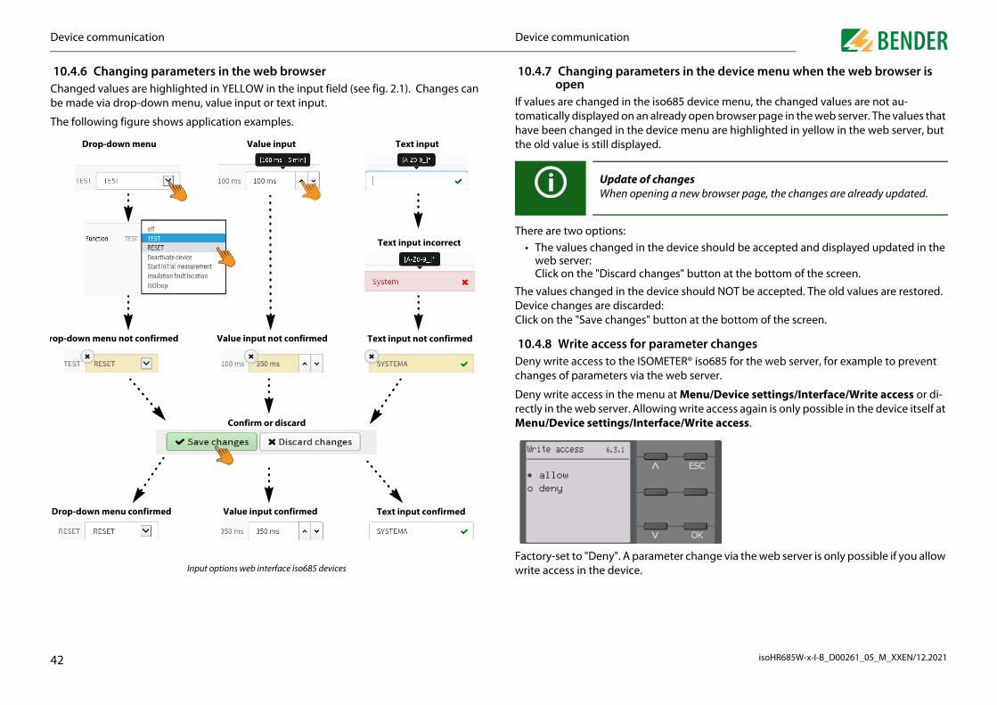
D
isoHR685W-x-I-B_D00261_05_M_XXEN/12.20214
1Cb
T
ro
D
eters in the device menu when the web browser is
iso685 device menu, the changed values are not au- already open browser page in the web server. The values that evice menu are highlighted in yellow in the web server, but d.
he device should be accepted and displayed updated in the
anges" button at the bottom of the screen.
evice should NOT be accepted. The old values are restored. ed: button at the bottom of the screen.
parameter changesMETER® iso685 for the web server, for example to prevent
he web server.
nu at Menu/Device settings/Interface/Write access or di-wing write access again is only possible in the device itself at rface/Write access.
ameter change via the web server is only possible if you allow
changesing a new browser page, the changes are already updated.
2
Input options web interface iso685 devices
Text input confirmedValue input confirmedrop-down menu confirmed
Factory-set to "Deny". A parwrite access in the device.
Device communicationevice communication
0.4.6 Changing parameters in the web browserhanged values are highlighted in YELLOW in the input field (see fig. 2.1). Changes can e made via drop-down menu, value input or text input.
he following figure shows application examples.
Drop-down menu Value input Text input
Text input incorrect
Text input not confirmedValue input not confirmedp-down menu not confirmed
Confirm or discard
10.4.7 Changing paramopen
If values are changed in thetomatically displayed on anhave been changed in the dthe old value is still displaye
There are two options: • The values changed in t
web server:Click on the "Discard ch
The values changed in the dDevice changes are discardClick on the "Save changes"
10.4.8 Write access for Deny write access to the ISOchanges of parameters via t
Deny write access in the merectly in the web server. AlloMenu/Device settings/Inte
Update ofWhen open
Write access 6.3.1
• allowo deny

D
isoHR685W-x-I-B_D00261_05_M_XXEN/12.20214
1Ttemfuw
1Tdreth
1Awre
1Tconnection. The number of devices on the BS bus is only limited by the BS bus master.
Unbmre
for the BS bus is a double-terminated bus topology. The limited to 1 m. These branch lines do not have to be
d on the RS-485 interface. The data transmission is binary/se-us data transmission must be guaranteed.
and parameters are stored in virtual register addresses. Data command on the register address. With a write command, gister address. The register addresses of the individual meas- can be found in the "iso685-D Annex A" manual with the title amily - Modbus settings" at www.bender.de/en/service-sup-
g resistor activated via switch on device (ON) or external ter-sistor between terminals A and B
g resistor deactivated via switch on device (OFF)g resistor activated via switch on device (ON) or external ter-sistor between terminals A and B
irst and last device may be terminated. Therefore, check all
�
2
2
2
2 2
� 2 2
2
3
3
se twisted pair, shielded cables for bus cabling. For example, cable type J-Y(St)Y x 2 x 0.8 is suitable. The shield must have a single-ended connection to earth. The BS us must be terminated at both ends with terminating resistors (120 Ω, 0.25 W). The ter-inating resistors are connected in parallel to the terminals A and B. Some devices featu- integrated terminating resistors and can be activated or deactivated via the "R" button.
Modbus RTU is implementerial. Error-free and continuo
Measured values, messagescan be read out with a readdata can be written into a reured values und parameters"ISOMETER® iso685 device fport/downloads.
Device communicationevice communication
0.5 BS bushe BS bus is used to extend Bender measuring devices (e.g. ISOMETER®) It is an RS-485 in-rface with a specially developed protocol for Bender devices. On the BS bus, the trans-ission of alarm messages takes priority over the transmission of all other messages. For rther information, refer to the BS bus manual (document number: D00278) at ww.bender.de/en/service-support/downloads .
0.5.1 Master-slave principlehe BS bus works according to the master-slave principle. This means that the measuring evice operates as the MASTER, while all sensor devices operate as SLAVES. The master is sponsible for the communication necessary for the measuring function. It also provides e required bus bias voltage for the operation of the BS bus.
0.5.2 Addresses and address ranges on the BS busddress 1 is assigned to the master. All sensor devices receive unique addresses starting ith address 2, assigned in consecutive order without gaps. In the event of a device failu-, a maximum gap of 5 addresses is permissible.
0.5.3 RS-485 specifications/cables he RS-485 specification restricts the cable length to 1200 m and requires a daisy chain
CAUTION
When using interface converters, a galvanic separation is required.
The compatibility of the BS bus and the BMS bus is restricted!
10.5.4 Cable routing The optimum cable routinglength of the branch line is terminated.
Bus topology examples:
Termination
10.6 Modbus RTU
1 MasterTerminatinminating re
2 Slave Terminatin
3 SlaveTerminatinminating re
CAUTION
Only the fdevices.
�
2
2
23 2
3
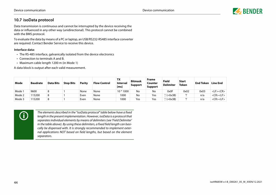
D
isoHR685W-x-I-B_D00261_05_M_XXEN/12.20214
1Ddw
Ta
In
A
M tart oken End Token Line End
M 0x02 0x03 <LF><CR>M '!' n/a <CR><LF>M '!' n/a <CR><LF>
separators.
4
Device communicationevice communication
0.7 isoData protocolata transmission is continuous and cannot be interrupted by the device receiving the ata or influenced in any other way (unidirectional). This protocol cannot be combined ith the BMS protocol.
o evaluate the data by means of a PC or laptop, an USB/RS232-RS485 interface converter re required. Contact Bender Service to receive this device.
terface data: • The RS-485 interface, galvanically isolated from the device electronics • Connection to terminals A and B. • Maximum cable length 1200 m (in Mode 1)
data block is output after each valid measurement.
ode Baudrate Data Bits Stop Bits Parity Flow ControlTX Interval [ms]
Bitmask Support
Frame Counter Support
Field Delimiter
ST
ode 1 9600 8 1 None None 10 * 1000 No No 0x0Fode 2 115200 8 1 Even None 1000 No Yes ';' (=0x3B)ode 3 115200 8 1 Even None 1000 Yes Yes ';' (=0x3B)
The elements described in the "isoData protocol" table below have a fixedlength in the present implementation. However, isoData is a protocol thatseparates individual elements by means of delimiters (see 'Field Delimiter'in the table above). By using these delimiters, a fixed field length can basi-cally be dispensed with. It is strongly recommended to implement exter-nal applications NOT based on field lengths, but based on the element

D
isoHR685W-x-I-B_D00261_05_M_XXEN/12.20214
1
D ring Mode
1 2 3Dfo
- 0 0
Dfo
0 - -
A - - 1
D - - 2
T mm - - 3
In - 1 -
IsD
- 8 4
IsB
6 - -
InB
1 - -
inL
- 2 -
inD
- - 5
M - 11 6
L - 3 7
V - - 8
V - - 9
V - - 10
V - 5 -
V - 6 11
evice communication
5
0.7.1 isoData-protocol table
escription Length [Bytes] Value Unit Example st
ata packet start character r modes 2 and 3
1 ! !
ata packet start character r mode 1
1 0x02 0x02
vailable Bitmask 8 Dependent on the fields included. (Bitmask) FFFFFFFF
ate 8 Current date dd.mm.yy
ime 12 Current time hh:mm:ss:m
sulation fault location 1' ' = symmetrical fault '+' = Fault on L1/+ '–' = Fault on L3/-
x
olation fault location etailed overview
4Insulation fault percentage distribution from 100 … +100
% +123
olation fault locationrief overview
10 = AC fault 1 = DC- fault 2 = DC+ fault
0
sulation resistance rief overview
6 RF kΩ 123456
sulation resistanceimited overview
6 RF Note: Value limited to 9.9 MΩ kΩ 1234.5
sulation resistanceetailed overview
9 RF Note: Value limited to 9.9 MΩ kΩ 1234567.8
easured value counter 2Increased with each new measured value. Integer overflow at 99.
12
eakage capacitance Ce 4R Mode [μF] Z Mode [nF] Note: Z Mode is not supported.
μF (R-Mode) nF (Z-Mode)
1234
oltage Un (VRMS) L1-L2 7Voltage bewteen phase L1 and phase L2. RMS value, unsigned.
V 12345.6
oltage Un (VRMS) L1-L3 7Voltage between phase L1 and phase L3. RMS value, unsigned.
V 12345.6
oltage Un (VRMS) L2-L3 7Voltage between phases L2 and L3. RMS value, unsigned.
V 12345.6
oltage Un (VRMS) 5Voltage between phases L1 and L2. RMS value, signed AC Net ' ' DC system always signed with '+'
V +1234
oltage Un (VRMS) L1-PE 5Voltage between phase L1 and PE. RMS value, Note: always signed with '+'
V 1234

D
isoHR685W-x-I-B_D00261_05_M_XXEN/12.20214
V - - 12
V - 7 13
M - - 14
V - - 15
A - 10 16
B - + +BIn - + +
BIn - + +
BS - + +
BIn - + +
BIn - + +
BS - + +
BIn - + -
BIn - + -
BU - + -
BO - + -
B - + +
B - + -
D ring Mode
evice communication
6
oltage Un (VRMS) L2-PE 5Voltage between phase L2 and PE. RMS value, Note: always signed with '+'
V 1234
oltage Un (VRMS) L3-PE 5Voltage between phase L3 and PE. RMS value, Note: always signed with '+'
V 1234
easurement quality 3
Quality of measured value 0 % = Poor quality => Change profile 100 % = good quality => Profile fits the application
% 100
oltage DC-PE 4 DC offset voltage to earth V +123
larm messages 4[Hexadezimal] (with leading „0x“) In this value, the messages are included with the OR function
BIT 1234
it2: Device error n/a 0x0002 Bitmaskeit3: Prewarning sulation fault RF on L1/+ n/a 0x0004 Bitmask
it4: Prewarning sulation fault RF on L2/- n/a 0x0008 Bitmask
it5: Prewarning ymmetrical insulation fault RF n/a 0x000C Bitmask
it6: Alarm sulation fault RF on L1/+ n/a 0x0010 Bitmask
it7: Alarm sulation fault RF on L2/- n/a 0x0020 Bitmask
it8: Alarm ymmetrical insulation fault RF n/a 0x0030 Bitmask
it9: Prewarning sulation impedance ZF
n/a 0x0040 Note: Currently not supported Bitmask
it10: Alarm sulation impedance ZF
n/a 0x0080 Note: Currently not supported Bitmask
it11: Alarm ndervoltage Un
n/a 0x0100 Note: Currently not supported Bitmask
it12: Alarm vervoltage Un
n/a 0x0200 Note: Currently not supported Bitmask
it13: System test message n/a 0x0400 Bitmask
it14: Device starts with alarm n/a 0x0800 Note: Currently not supported Bitmask
escription Length [Bytes] Value Unit Example st
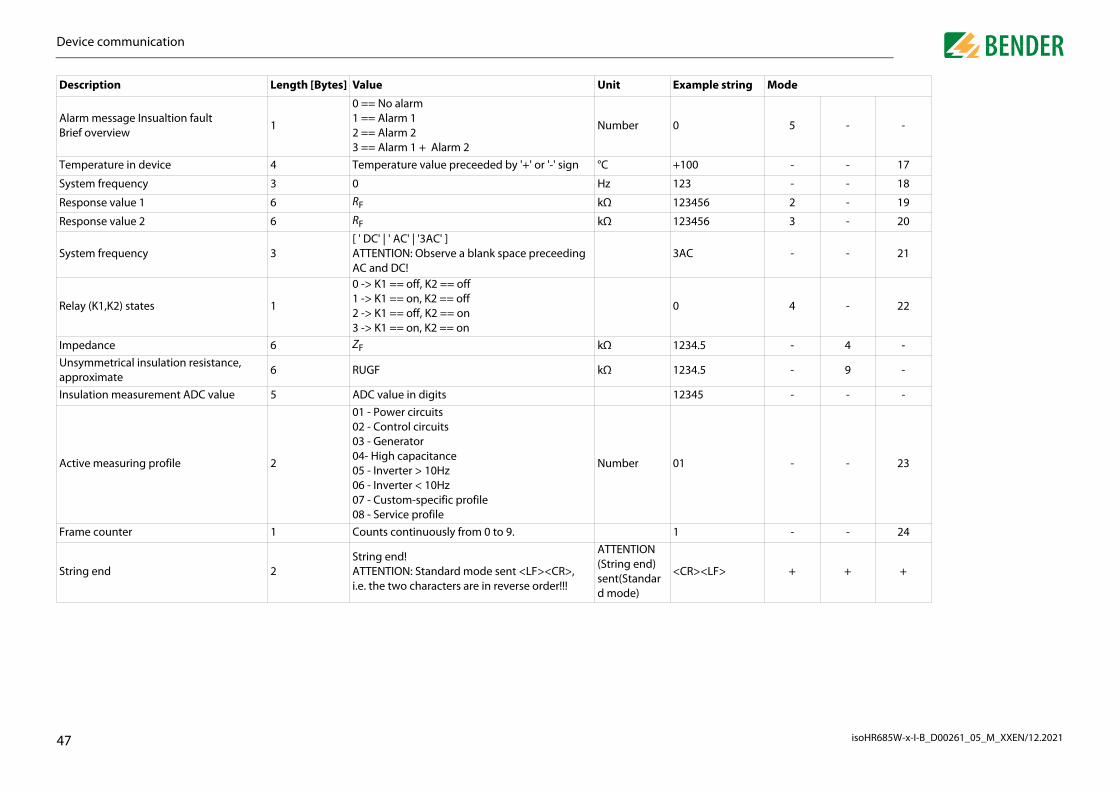
D
isoHR685W-x-I-B_D00261_05_M_XXEN/12.20214
AB
5 - -
T - - 17
S - - 18
R 2 - 19
R 3 - 20
S - - 21
R 4 - 22
Im - 4 -Ua
- 9 -
In - - -
A - - 23
F - - 24
S + + +
D ring Mode
evice communication
7
larm message Insualtion faultrief overview
1
0 == No alarm 1 == Alarm 1 2 == Alarm 2 3 == Alarm 1 + Alarm 2
Number 0
emperature in device 4 Temperature value preceeded by '+' or '-' sign °C +100
ystem frequency 3 0 Hz 123
esponse value 1 6 RF kΩ 123456
esponse value 2 6 RF kΩ 123456
ystem frequency 3[ ' DC' | ' AC' | '3AC' ] ATTENTION: Observe a blank space preceeding AC and DC!
3AC
elay (K1,K2) states 1
0 -> K1 == off, K2 == off 1 -> K1 == on, K2 == off 2 -> K1 == off, K2 == on 3 -> K1 == on, K2 == on
0
pedance 6 ZF kΩ 1234.5nsymmetrical insulation resistance, pproximate
6 RUGF kΩ 1234.5
sulation measurement ADC value 5 ADC value in digits 12345
ctive measuring profile 2
01 - Power circuits 02 - Control circuits 03 - Generator 04- High capacitance 05 - Inverter > 10Hz 06 - Inverter < 10Hz 07 - Custom-specific profile 08 - Service profile
Number 01
rame counter 1 Counts continuously from 0 to 9. 1
tring end 2String end! ATTENTION: Standard mode sent <LF><CR>, i.e. the two characters are in reverse order!!!
ATTENTION (String end) sent(Standard mode)
<CR><LF>
escription Length [Bytes] Value Unit Example st

isoHR685W-x-I-B_D00261_05_M_XXEN/12.2021
d IT systems1
1WnITu
Ifc
ITri
1
V
er selected, first the connection to the IT system is restored ew measuring cycle for the insulation monitoring starts. This onnect the second ISOMETER® selectively in coupled IT sys-
ct of the coupling switch.
n via ISOnets via an Ethernet connection that only one ISOMETER® of the en several ISOMETER®s are connected to an IT system.
e able to measure in the same ISOnet interconnection, the m name and the BCOM subsystem have to be the same. Only different. If this is not taken into account, the ISOnet function
ctivated in an ISOMETER® in an ISOnet interconnection, it will will not forward measuring commands to the next device in
with coupling switches and function input, the response time e measurement in the IT system is not carried out conti-
TER®s in the ISOnet interconnection can be selected at will. to be subsequent but they have to differ from each other.
nterconnection the digital inputs are wired and a device is ut, the device will forward the measuring authorisation until t disappears. Afterwards, it participates again in the measu-
tion number of devices in an ISOnet interconnection: 20 devicesess of the standard gateway must suit the subnet mask, so thatfunction can operate correctly.
48
ing functions can be deactivated. Therefore, the function of the digital input in use has to be set to "Device inactive".
If the digital input used for this function is selected, the connectors "L1/+", "L2", "L3/-" are deactivated via internal system isolating switches, the measuring function stops and the following message appears on the display: "Device inactive. Device separated".
Stored fault messages are reset when the cause of the fault has been eliminated (RESET function).
the ISOnet
Special functions for couple1. Special functions for coupled IT systems
1.1 Particularities when monitoring coupled IT systemshen using ISOMETER®s in IT systems, make sure that only one active ISOMETER® is con-
ected in each interconnected system. If several ISOMETER®s are to be connected to the system, ensure that only one ISOMETER® is active in the IT system via system isolation sing the digital input or Ethernet (ISOnet function).
IT systems are interconnected via coupling switches, make sure that ISOMETER®s not urrently used are disconnected from the IT system and deactivated.
systems coupled via diodes or capacitances may also influence the insulation monito-ng process so that a central control of the different ISOMETER®s is required.
1.2 System isolation via digital input with two coupled systems
ia the X1 connector, the ISOMETER® can be isolated from the IT system and the measur-
In order to deactivate the ISOMETER® iso685-x-B via one of the dig-ital inputs, the coupling switch must have a free contact.
IT-System 1 IT-System 2
BCOM
Adr. 1BCOM
Adr. 2
If the digital input is no longand afterwards, an entirely nfunction can be used to disctems via the auxiliary conta
11.3 System isolatioThe ISOnet function ensureinterconnection is active wh
For several ISOMETER®s to bsettings for the BCOM systethe device address has to bewill not work.
If the ISOnet function is deameasure continuously and the interconnection.
In comparison to a solution will be extended because thnuously.
The addresses of the ISOMEThe addresses do not have
If in addition to the ISOnet ideactivated via a digital inpthe signal at the digital inpuring interconnection.
ConfiguraMaximumThe IP addr

d IT systemsS
isoHR685W-x-I-B_D00261_05_M_XXEN/12.20214
1 d function following settings are made in the menu: Alarm settings ISOnet function of all ISOMETER®s existing in the system has
ber of devices has to be determined in the menu Alarm devices.
thernet and BCOM have to be set so that the devices in the communicate with each other.
e devices initialise. The initialisation phase ends when the es has been reached. Then, the first device with the lowest ring cycle. When an ISOMETER® has finished one measuring nsulation measurement is forwarded to the ISOMETER® with ile one ISOMETER® is measuring, all other ISOMETER®s are
via internal system isolation switches. By limiting to one sub- several ISOnet interconnections running in one system.
maining ISOMETER®s continue the ISOnet operation. For the enarios are possible:easuring procedure.evice takes over the measuring function. onitor each other.
active mode.easuring authorisation, the device is skipped and the next easurement.
ore returns, it is taken into the interconnection again and can ring the next run.
ble to give the device in ISOnet mode a permanent priority in he priority from another device. While the function is set to Onet mode are inactive. The last requesting device always the device automatically returns to normal mode.
tion, priority can be requested or yielded in the Control -> .
eration ISOnet and ISOloop ISOloop must not be activated together, otherwise a measure-
t guaranteed.
9
11.3.3 ISOnet priorityThis function makes it possithe system or to take over tactive, all other devices in IShas priority. After 12 hours,
With the ISOnet priority funcISOnet priority menu
Special functions for couplepecial functions for coupled IT systems
1.3.1 Systempictures
System 1 System 2
1. 2.
3. 4.
SWITCH
11.3.2 Configuration anFor the ISOnet function, the-> ISONet -> BCOM. Theto be activated and the numsettings -> Number of
Also the parameters of the EISOnet interconnection can
After starting the system, thconfigured number of devicaddress starts with a measucycle, the authorisation for ithe next higher address. Whseparated from the system system it is possible to have
If a single device fails, the refailure of one device, two sc • A device fails during a m
After timeout, another dIn this way, all devices m
• The device fails in the inWhen forwarding the mdevice carries out the m
If a device that has failed befcarry out a measurement du
Parallel opISOnet andment is no

d IT systemsS
isoHR685W-x-I-B_D00261_05_M_XXEN/12.20215
1RtorathdW
Ifdpthd
the lowest BCOM address in a team (in the example, device 1) sured insulation value to all team members (here device 2). alue subscription" can be used to define whether this shared wn on the respective device. If this function is activated, de-insulation alarm 1 and 2 based on the selected alarm thres-ted by default.
ction is the combination of several ISOMETER®s to form an in-g of up to 10 ISOMETER®s is carried out with a separate soft-ager. The program can be downloaded from the Bender service-support/downloads or via the web server ("Menu" > t\groupcfg.zip). The tested setup file can be executed on any .
vices in an interconnectioneration of different devices within an interconnection, each ith a valid BCOM address. The respective system name must all devices.
Information on the configuration of BCOM in the device menu can be found in chapter n about BCOM can be found in chapter 10.2 BCOM in this ma-al (D00256) atice-support/downloads.
eration ISOnet and ISOloop ISOloop should not be activated simultaneously since the twore opposed. In ISOnet mode, the measuring task is assigned cy-ll devices in the system, while in ISOloop mode, the measuring
ays assigned to the device with the lowest address within a de-onnection.
tem name configuration in the interconnection must have a common device name.
0
9.2 (6.3.3) BCOM. Informationual and in the BCOM manu http://www.bender.de/serv
Special functions for couplepecial functions for coupled IT systems
1.4 ISOlooping systems are a special type of coupled systems in which all systems can be coupled form a ring interconnection. The ISOloop function ensures that, in a system with seve-l insulation monitoring devices, one device is always actively measuring. The devices at work in an ISOloop configuration are combined into a group. Within the group,
igital inputs are used to control which devices are currently working together in a team. ithin the team, the device with the lowest BCOM address takes over the measuring task.
the systems are coupled via the coupling switches, the devices receive a signal via the igital input informing them that they are now working together as a team. If only the up-er coupling switch is closed, device 1 and device 2 are in a team and device 1 takes over e measuring task. If all coupling switches are closed, all four devices are in one team and
evice 1 takes over the measuring task.
PGH ONPGH ON
PGH ONPGH ON
Switch
1 2
4 3
The measuring device with distributes its currently meaThe parameter "Measured vmeasured value is to be shovice 2 would also report an holds. This function is activa
The basis of the ISOloop funterconnection. The groupinware, the BCOM Group Manwebsite at www.bender.de/"Settings" > "File" \wwwrooWindows PC in the network
11.4.1 Preparing the deIn order to enable the coopdevice must be provided wbe configured uniformly for
Parallel opISOnet andfunctions aclically to atask is alwfined interc
BCOM sysAll devices

d IT systemsS
isoHR685W-x-I-B_D00261_05_M_XXEN/12.20215
1Tg
1
1
Sswnsuti
Remove all devices from the groupDelete all connect
contain all connections that exist in the installation. The follo-ections for the above example.
p have been made, the configuration file is saved.
of the configuration file of the configuration file of the ISOloop interconnection is.cfg". The name must not be changed, since every ISOMETER®e information about the ISOloop interconnection from a file
ly this name. For documentation purposes, we recommend sa-e in a zip file, the name of which can then be changed.
aximum of 10 addresses (devices) in one interconnection
net specification in an interconnection (different subnets possible)
ely selectable device description Target address for "loop" information. Each device requires a target in the interconnection
1
1.4.2.2 Switching rules
ource and target define the two devices that work together in a team when the coupling itch connected to the source is closed. (Example: The upper coupling switch is con-
ected to device 1 => source is device 1 and target is device 2. Each combination of bnet and device address may only exist once as source and target in an interconnec-
on. Each device requires exactly and exclusively one other device as target.
File nameThe name"grp_0102receives thwith exactving the fil
Special functions for couplepecial functions for coupled IT systems
1.4.2 Creating groups with the BCOM Group Managerhe BCOM Group Manager provides help for creating ISOMETER® groups. Open the pro-ram and select ISOloop mode.
1.4.2.1 Creating groups
Add a device to the group
Remove a device from the group
Add connection
Delete connection
The "Connection List" must wing figure shows the conn
After all settings of the grou
A m
Sub
Fre

d IT systemsS
isoHR685W-x-I-B_D00261_05_M_XXEN/12.20215
1
Tb
1
2
3
4
5
6
7
8
9
1
1
le is available for download in the download area of each
d function on the ISOMETER®bled or disabled in the menu at Alarm settings -> ISO-e activated and configured for all ISOMETER®s in the system ously.
ISOloop interconnection to communicate with each other, on or IP address, subnet mask and default gateway) must be loop function.
> ISOloop Activate ISOloop function
Inputs -> Digital input X Select ISOloop as function
nctionop function is not activated before the Group Manager file is
or if the devices do not have valid IP/BCOM parameters, the filematically distributed in the system.
2
. Select target folder "group" (1.)
. Select file "grp_0102.cfg" in the corresponding folder of your source PC (2.)
. In the target path line (3.), the following must appear after the symbol: \group\grp_0102.cfg
0. Start the upload by pressing the "Save" button (4.)
1. The configuration settings of the interconnection are automatically distributed after completing the procedure.
Special functions for couplepecial functions for coupled IT systems
1.4.2.3 Transferring the configuration file to an ISOMETER®
he configuration file is installed via the web user interface of the iso685-x-P device in the rowser of a computer in the network. Proceed as follows:
. Apply a supply voltage to all correctly connected devices in the interconnection.
. Parameterise the Ethernet settings for all devices and check that the devices can communicate via Ethernet.
. Parameterise the BCOM addresses created in the Group Manager for all devices
. Activate the ISOloop function on all devices
. Enter the IP address of the device to which you want to upload the configuration file in the browser window.
. Navigate to the following menu item: "Device" > "Menu" > "Settings" > "File"The following input window appears in the content area of the COMTRAXX® user interface.
All devices in the interconnection must be switched onThe ISOloop information is transferred from device to device according toan address sequence defined in the configuration. Therefore, when uploa-ding the configuration file, all devices in the interconnection must be swit-ched on and connected to the network.
After completion, the fidevice:
11.4.3 Configuration anThe ISOloop function is enaloop . The function must bthat have to work synchron
To enable the devices in thethe Ethernet settings (DHCPmade in addition to the ISO
Menu Alarm settings -
Menu Alarm settings ->
ISOloop fuIf the ISOlouploaded, is not auto
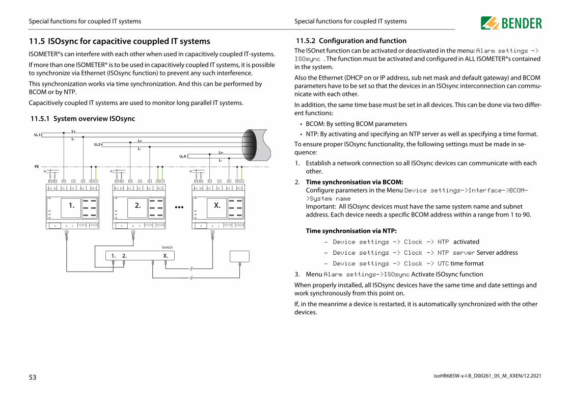
d IT systemsS
isoHR685W-x-I-B_D00261_05_M_XXEN/12.20215
1IS
Ifto
TB
C
1
d functionactivated or deactivated in the menu: Alarm settings -> st be activated and configured in ALL ISOMETER®s contained
or IP address, sub net mask and default gateway) and BCOM o that the devices in an ISOsync interconnection can commu-
ase must be set in all devices. This can be done via two differ-
parameters
pecifying an NTP server as well as specifying a time format.
nctionality, the following settings must be made in se-
nection so all ISOsync devices can communicate with each
via BCOM:n the Menu Device settings->Interface->BCOM-
devices must have the same system name and subnet eds a specific BCOM address within a range from 1 to 90.
via NTP:
ings -> Clock -> NTP activated
ings -> Clock -> NTP server Server address
ings -> Clock -> UTC time format
s->ISOsync Activate ISOsync function
When properly installed, all ISOsync devices have the same time and date settings and is point on.
is restarted, it is automatically synchronized with the other
3
work synchronously from th
If, in the meanrime a devicedevices.
Special functions for couplepecial functions for coupled IT systems
1.5 ISOsync for capacitive couppled IT systems OMETER®s can interfere with each other when used in capacitively coupled IT-systems.
more than one ISOMETER® is to be used in capacitively coupled IT systems, it is possible synchronize via Ethernet (ISOsync function) to prevent any such interference.
his synchronization works via time synchronization. And this can be performed by COM or by NTP.
apacitively coupled IT systems are used to monitor long parallel IT systems.
1.5.1 System overview ISOsync
PE
L+
L-U Xn
U 2nL+
L-
L+
L-U 1n
X2
11 12 14 21 22 24RX2X1
KE EL2 L3/-L1/+A2/-A1/+
A1/+ A2/- L1/+ L2 L3/- KE E
US
X2
11 12 14 21 22 24RX2X1
KE EL2 L3/-L1/+A2/-A1/+
A1/+ A2/- L1/+ L2 L3/- KE E
US
X2
11 12 14 21 22 24RX2X1
KE EL2 L3/-L1/+A2/-A1/+
A1/+ A2/- L1/+ L2 L3/- KE E
US
Switch
1. 2. X.
1. 2. X.
11.5.2 Configuration anThe ISOnet function can be ISOsync . The function muin the system.
Also the Ethernet (DHCP onparameters have to be set snicate with each other.
In addition, the same time bent functions:
• BCOM: By setting BCOM
• NTP: By activating and s
To ensure proper ISOsync fuquence:
1. Establish a network conother.
2. Time synchronisationConfigure parameters i>System nameImportant: All ISOsync address. Each device ne Time synchronisation
– Device sett
– Device sett
– Device sett
3. Menu Alarm setting
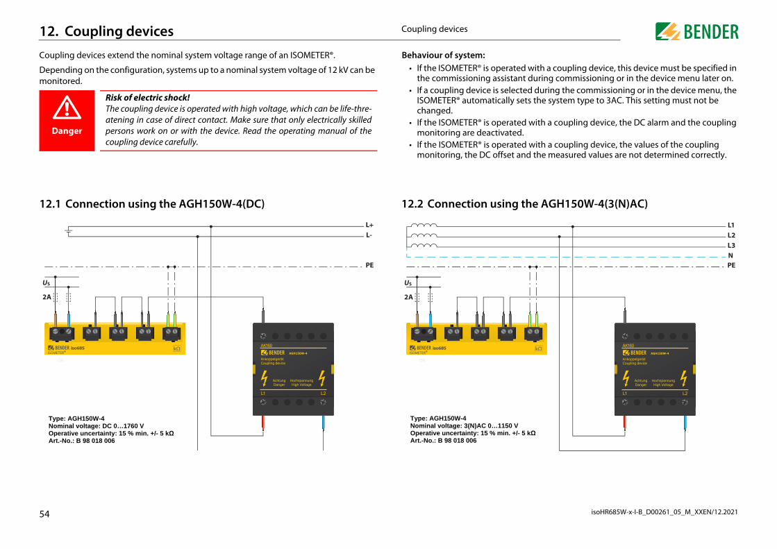
isoHR685W-x-I-B_D00261_05_M_XXEN/12.2021
1C
Dm
1
U
2
rated with a coupling device, this device must be specified in stant during commissioning or in the device menu later on.lected during the commissioning or in the device menu, the
lly sets the system type to 3AC. This setting must not be
rated with a coupling device, the DC alarm and the coupling ted.
rated with a coupling device, the values of the coupling et and the measured values are not determined correctly.
g the AGH150W-4(3(N)AC)
PE
L1L2L3N
0 V. +/- 5 kΩ
54
Type: AGH150W-4Nominal voltage: DC 0…1760 VOperative uncertainty: 15 % min. +/- 5 kΩArt.-No.: B 98 018 006
Type: AGH150W-4Nominal voltage: 3(N)AC 0…115Operative uncertainty: 15 % minArt.-No.: B 98 018 006
Coupling devices2. Coupling devicesoupling devices extend the nominal system voltage range of an ISOMETER®.
epending on the configuration, systems up to a nominal system voltage of 12 kV can be onitored.
2.1 Connection using the AGH150W-4(DC)
Danger
Risk of electric shock! The coupling device is operated with high voltage, which can be life-thre-atening in case of direct contact. Make sure that only electrically skilledpersons work on or with the device. Read the operating manual of thecoupling device carefully.
PE
S
A
L+L-
Behaviour of system: • If the ISOMETER® is ope
the commissioning assi • If a coupling device is se
ISOMETER® automaticachanged.
• If the ISOMETER® is opemonitoring are deactiva
• If the ISOMETER® is opemonitoring, the DC offs
12.2 Connection usin
US
2A

C
isoHR685W-x-I-B_D00261_05_M_XXEN/12.20215
1
U
2
g the AGH520S (3(N)AC)
PE
L1L2L3N
n. +/- 5 kΩ
5
Coupling devicesoupling devices
2.3 Connection using the AGH520S (3AC)
PE
S
A
L1L2L3
Type: AGH520SNominal voltage: AC 0…7200 VOperative uncertainty: 15 % min. +/- 5 kΩArt.-No.: B 913 033
12.4 Connection usin
US
2A
Type: AGH520SNominal voltage: AC 0…7200 VOperative uncertainty: 15 % miArt.-No.: B 913 033

C
isoHR685W-x-I-B_D00261_05_M_XXEN/12.20215
1
U
2
g the AGH676S-4
PE
L1L2L3N
. +/- 5 kΩ
6
Coupling devicesoupling devices
2.5 Connection using the AGH204S-4
PE
S
A
L1L2L3N
Type: AGH204S-4Nominal voltage with rectifier: AC 0...1300 VNominal voltage without rectifier: AC 0...1650 VOperative uncertainty: 15 % min. +/- 5 kΩArt.-No.: B 914 013
A) with rectifierB) without rectifier
A B
12.6 Connection usin
US
2A
Type: AGH676S-4Nominal voltage: AC 12 kVOperative uncertainty: 15 % minArt.-No.: B 913 055

isoHR685W-x-I-B_D00261_05_M_XXEN/12.2021
LED indicators
red systemutton "ALARM 1" is lit
ng monitoredutton "ALARM 2" is lit
f DC compo-
LED indicators
d "L3/-" to the
"ALARM 1" + "ALARM 2" flash alternately
to earth (PE) "ALARM 1" + "ALARM 2" flash in common mode
ins frequency
tion the cha-
ays)erface
the device
57
13. Alarm messages
13.1 Measured value alarmsAlarm messages are activated directly after switching on and can occur immediately.
13.2 GeneralAlarm messages are activated directly after switching on and can occur immediately.
Alarm message Description Measures
Insulation faultAn insulation fault exists. The insulation resistance falls below the response value Ran1.
• Observe insulation resistance in the monito• Reset fault message by pressing the reset b
Insulation faultAn insulation fault exists. The insulation resistance falls below the response value Ran2.
• Eliminate insulation fault in the system bei• Reset fault message by pressing the reset b
DC offset voltage There is a DC offset voltage in the system.• Check insulation fault and eliminate fault o
nents
Alarm message Description Measures
Undervoltage Operating outside the specified supply voltage range • Check supply voltage
Overvoltage Operating outside the specified supply voltage range • Check supply voltage
Check L1-L2-L3 for correct connection!
No low-resistance connection between the line conductors^
• Check the wiring of terminals "L1/+", "L2" anIT system
• Press the TEST button• Check nominal system voltage• Check fuses• Check set system type
Check E-KE connections for interruptions!
No low-resistance connection between terminals "E" and "KE" to earth (PE)
• Check the wiring of terminals "E" and "KE" • Press the TEST button
The profile does not suit the application!
Wrong profile selected for this application
• Check measured system capacitance or main the "Info" menu
• Select another profile taking into consideraracteristics
Load on X1 too high! Sum of the external loads on "X1" too high• Check load on X1.+, X1.Q1 and X1.Q2• Check ambient temperature
Check date and time! Date and time have not been set yet• Set local date and time
(in case of voltage failure buffer for three d
No DHCP server found! Connection problem at the Ethernet interface• Check cable connection at the Ethernet int• Check the DHCP server availability• Check the DHCP interface configuration in

A
isoHR685W-x-I-B_D00261_05_M_XXEN/12.20215
1Th
D "SERVICE" is lit
Df DC compo-
S
Bin
up Manager
S "SERVICE" is lit
A LED indicators
D
F
N
A LED indicators
larm messages
8
3.3 ISOnetese messages only become active after activating the ISOnet function.
evice error x.xx Internal device error• Press the TEST button• Switch the supply voltage off and on• Contact Bender service
C offset voltage There is a DC offset voltage in the system.• Check insulation fault and eliminate fault o
nents
ynchronizing ...The device synchronises over a longer period of time. (longer than five minutes)
• Restart
COM connection terrupted!
No connection to devices can be made within the BCOM system due to - an interrupted bus conductor- incorrect Ethernet settings- incorrect grouping
• Connect bus conductor correctly• Correct Ethernet settings• Restore configuration using the BCOM Gro
ervice mode active! The device is in maintenance condition • Contact Bender service
larm message Description Measures
isturbance ISOnetEthernet connection of the ISOMETER® is disturbed (e.g. due to a cable defect or the failure of a switch)
• Check Ethernet connection• Check device function• Switch the supply voltage off and on
ailure address
Active ISOnet interconnection devices detect that one or more devices are no longer accessible. This message is the counter-information on the active devices to the message "Disturbance ISOnet"
• Check Ethernet connection• Check device function
um. ISOnet devicesThe configuration between existing ISOnet devices and set ISOnet devices is different
• Check settings• Check Ethernet connection
larm message Description Measures

A
isoHR685W-x-I-B_D00261_05_M_XXEN/12.20215
1Th
A LED indicators
ISu
e configured BCOM and
to a device via
ISfa
Tw
EIS
larm messages
9
3.4 ISOloopese messages only become active after activating the ISOloop function.
larm message Description Measures
Oloop configuration is not niform!
The ISOloop group configuration is not uniform for all devices in the group or one of the devices has no configura-tion
• Make sure that all devices in the group to bare able to communicate (correctly set andEthernet connection established).
• Afterwards, upload ISOloop configuration the web server
Oloop configuration is ulty!
Addresses of the group configuration (system-subsystem-device address) do not match the addresses on the devices in this group
• see above
he ISOloop configuration as not found!
There is no ISOloop configuration on this device• see above
rror while distributing the Oloop configuration!
The ISOloop configuration could not be distributed to all devices (devices were not switched on or faulty BCOM con-nection) OR function was not activated when uploading the configuration file OR function was not activated on all devices during upload
• see above

isoHR685W-x-I-B_D00261_05_M_XXEN/12.2021
Description
Main circuits without dynamic frequency changes.The universal profile is suitable for all systems primarily with constant mains frequencies and extraneous DC voltages. When using inverters and dynamic frequency control, select inverters > 10 Hz or inverters < 10 Hz.This profile is used to reduce the measurement voltage to ±10 V in con-trol systems with lower nominal voltages in order to reduce the impact by the ISOMETER® on sensitive switching elements. This profile allows the realisation of a very fast measuring time, e.g. as required for generator monitoring. Furthermore, this profile can be used to support fast fault localisation in an IT system. The generator profile is suitable for AC systems containing DC components.For systems with high leakage capacitances, e.g. ship applications, the impact of leakage capacitances on the measuring result can be signifi-cantly reduced by selecting this profile.This profile is used for systems with dynamic frequency control by invert-ers in the range 10 to 460 Hz in order to optimise the measurement with respect to the measuring time and quality.For systems involving extremely low frequency control in the range of up to 0.1...460 Hz and very low and continuously changing extraneous DC voltages due to dynamic load conditions in an IT system, continuous insulation monitoring can be optimised using this profile. *Allows Bender service to make customer-specific settings. If no settings are made by Bender service, then the profile has the same parameters as the "Power circuits" profile.
w frequency mains voltage very low frequency networks, the nominal system voltage is reducedording to the specifications in the chapter "Technical data" .
60
14. Technical data
14.1 Device profiles isoHR685W-x-I-BAdjustment to different applications can be carried out very easily by selecting a device profile.
For response times, refer „Device profiles“ at the follwing sections.
Nominal system voltage
System frequency
System leakage capacitance
Measuring voltage
Measuring range
Response values
Power cirquitAC 0…1000 V3AC 0…690 VDC 0…1300 V
15…460 Hz 0…150 μF ± 50 V 0,1 kΩ…10 GΩ 1 kΩ…3 GΩ
Control cirquitAC 0…230 V3AC 0…230 VDC 0…230 V
15…460 Hz 0…150 μF ± 10 V0,1 kΩ…<1 MΩ
1 kΩ…950 kΩ
Generator AC 0…690 V3AC 0…690 V
50…60 Hz 0…5 μF ± 50 V 0,1 kΩ…1 MΩ 1 kΩ…950 kΩ
High capacitanceAC 0…1000 V3AC 0…690 VDC 0…1300 V
15…460 Hz 0…1000 μF ± 50 V 0,1 kΩ…10 GΩ 1 kΩ…3 GΩ
Inverter > 10 HzAC 0…1000 V3AC 0…690 VDC 0…1300 V
10…460 Hz 0…20 μF ± 50 V 0,1 kΩ…1 MΩ 1 kΩ…950 kΩ
Inverter <10 HzAC 0…1000 V3AC 0…690 VDC 0…1300 V
0,1…460 Hz 0 …20 μF ± 50 V 0,1 kΩ…1 MΩ 1 kΩ…950 kΩ
Customer specific – – – – – –
Switching between profilesWhen another profile is selected, the value of Rmin is reset.Switching between profiles can result in longer measuring times.
* LoForacc
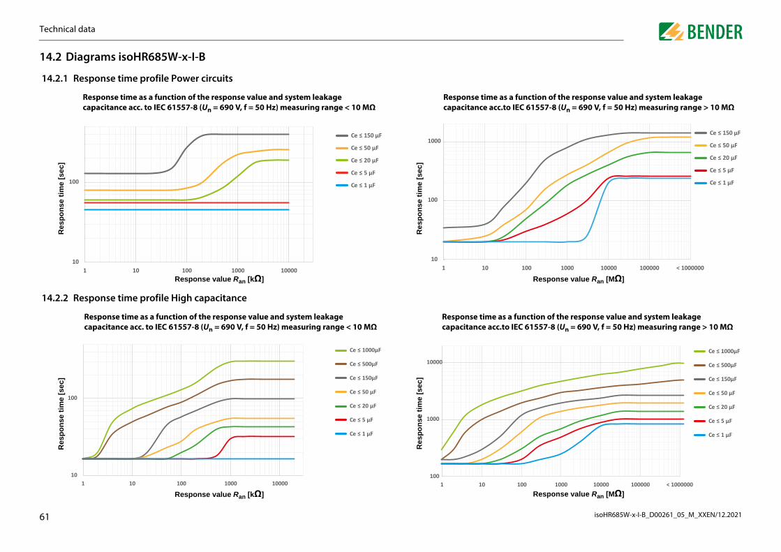
Te
isoHR685W-x-I-B_D00261_05_M_XXEN/12.20216
1
1
1
function of the response value and system leakage IEC 61557-8 (Un = 690 V, f = 50 Hz) measuring range > 10 MΩ
Response value Ran [MΩ]100 1000 10000 100000 < 1000000
Ce � 150 μF
Ce � 50 μF
Ce � 20 μF
Ce � 5 μF
Ce � 1 μF
function of the response value and system leakage EC 61557-8 (Un = 690 V, f = 50 Hz) measuring range > 10 MΩ
Response value Ran [MΩ]100 1000 10000 100000 < 1000000
Ce � 1000μF
Ce � 500μF
Ce � 150μF
Ce � 50 μF
Ce � 20 μF
Ce � 5 μF
Ce � 1 μF
chnical data
1
4.2 Diagrams isoHR685W-x-I-B
4.2.1 Response time profile Power circuits
4.2.2 Response time profile High capacitance
Response time as a function of the response value and system leakage capacitance acc. to IEC 61557-8 (Un = 690 V, f = 50 Hz) measuring range < 10 MΩ
Response value Ran [kΩ]
Res
pons
e tim
e [s
ec]
Response time as acapacitance acc.to
Res
pons
e tim
e [s
ec]
10
100
1 10 100 1000 10000
Ce � 150 μF
Ce � 50 μF
Ce � 20 μF
Ce � 5 μF
Ce � 1 μF
10
100
1000
1 10
Response time as acapacitance acc.to I
Res
pons
e tim
e [s
ec]
Response time as a function of the response value and system leakage capacitance acc. to IEC 61557-8 (Un = 690 V, f = 50 Hz) measuring range < 10 MΩ
Response value Ran [kΩ]
Res
pons
e tim
e [s
ec]
10
100
1 10 100 1000 10000
Ce � 1000μF
Ce � 500μF
Ce � 150μF
Ce � 50 μF
Ce � 20 μF
Ce � 5 μF
Ce � 1 μF
100
1000
10000
1 10

Tech
isoHR685W-x-I-B_D00261_05_M_XXEN/12.20216
14.
14.
imrofile Inverter > 10 Hz
rofile Inverter < 10 Hz
a function of the response value and system leakage o IEC 61557-8 (Un = 690 V, f = 50 Hz) measuring range < 10 MΩ
Response value Ran [kΩ]10 100 1000
Ce � 20 μF
Ce � 5 μF
Ce � 1 μF
a function of the response value and system leakage o IEC 61557-8 (Un = 690 V, f = 50 Hz) measuring range < 10 MΩ
Response value Ran [kΩ]
im
10 100 1000
Ce � 20μF
Ce � 5 μF
Ce � 1 μF
2
Response value Ran [kΩ]
Res
pons
e t
11 10 100 1000
p
Res
pons
e t
101
Technical datanical data
2.3 Response time profile Control circuits
2.4 Rsponse time profile Generator
Response time as a function of the response value and system leakage capacitance acc. to IEC 61557-8 (Un = 690 V, f = 50 Hz) measuring range < 10 MΩ
Response value Ran [kΩ]
Res
pons
e tim
e [s
ec]
1
10
100
1 10 100 1000
Ce � 150μF
Ce � 100μF
Ce � 50μF
Ce � 10μF
Ce � 1μF
Response time as a function of the response value and system leakage capacitance acc. to IEC 61557-8 (Un = 690 V, f = 50 Hz) measuring range < 10 MΩ
e [s
ec]
10
[]
Ce � 5μF
Ce � 1μF
14.2.5 Response time p
14.2.6 Response time p
Response time ascapacitance acc. t
Res
pons
e tim
e [s
ec]
10
100
1
p[
]
Response time ascapacitance acc. t
e [s
ec]
100

Te
isoHR685W-x-I-B_D00261_05_M_XXEN/12.20216
1
1
mes for DC alarm for RF depending on system profile and acitance (isoHR685W-x-I-B)
System leakage capacitance [µF]
High capacitanceInverter < 10 HzInverter > 10 Hz
1 10 100
ncertainty as a function of the response value and itance according to IEC 61557-8 (Un = 690 V, f = 50 Hz) MΩ
Response value Ran [MΩ]0,1 1 10 100 1000
Ce≤ 1 μF
Ce≤ 150 μF
chnical data
3
4.2.7 Response time DC Alarm
4.2.8 Relative uncertainty
1
10
100
1000
0 1 10 100
Typical response times for DC alarm for RF depending on system profile and system leakage capacitance (iso685-variants)
System leakage capacitance [µF]
Res
pons
e tim
e [s
ec]
Power cirquitControl cirquit High capacitance
Inverter < 10 HzInverter > 10 Hz
Typical response tisystem leakage cap
Res
pons
e tim
e [s
ec]
Power cirquitControl cirquit
1
10
100
1000
0
Percentage relative uncertainty as a function of the response value and system leakage capacitance according to IEC 61557-8 (Un = 690 V, f = 50 Hz) measuring range < 10 MΩ
Response value Ran [kΩ]
Rel
ativ
e un
cert
aint
y [%
]
Percentage relative usystem leakage capacmeasuring range > 10
Rel
ativ
e un
cert
aint
y [%
]
0%
10%
20%
30%
40%
50%
60%
70%
80%
90%
100%
0,1 1 10 100 1000 10000 100000
Ce≤ 1 μF
Ce≤ 1000 μF
0%
10%
20%
30%
40%
50%
60%
70%
80%
90%
100%
0,001 0,01
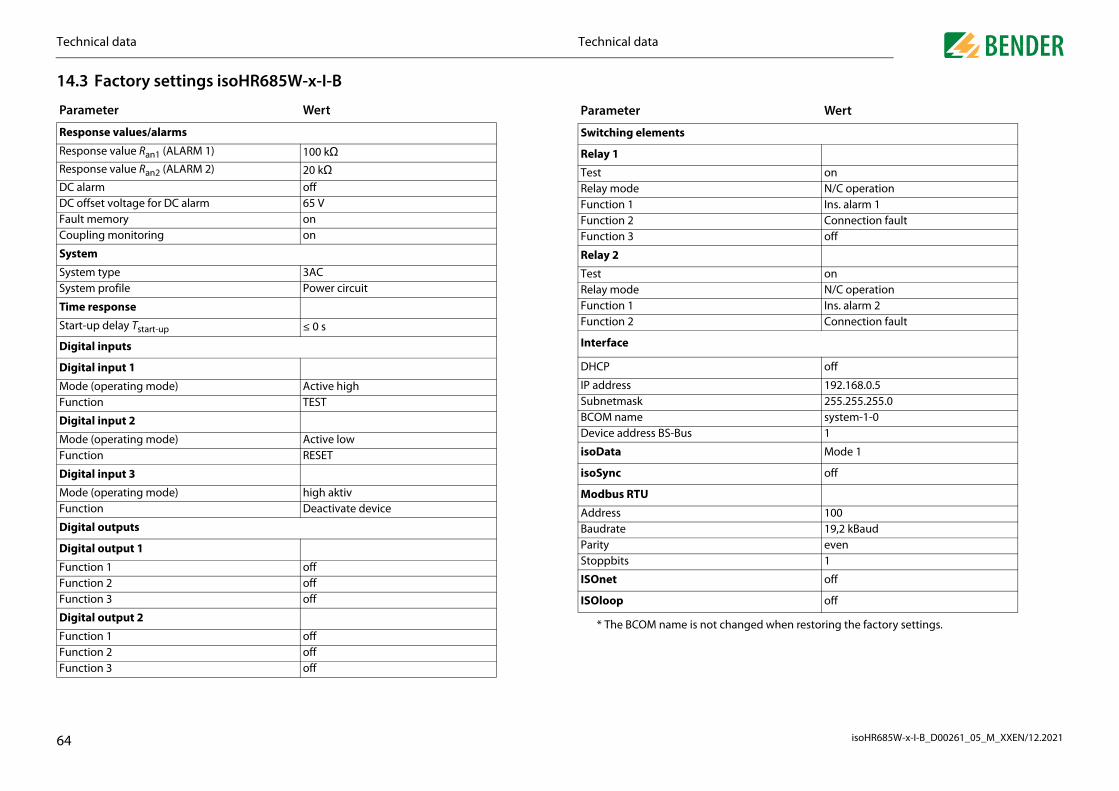
Techn
isoHR685W-x-I-B_D00261_05_M_XXEN/12.20216
14.3
Param
Respo
Respo
Respo
DC alaDC offFault mCoupli
System
SystemSystem
Time r
Start-u
Digita
Digita
Mode Functi
Digita
Mode Functi
Digita
Mode Functi
Digita
Digita
FFF
D
FFF
anged when restoring the factory settings.
nts
onN/C operationIns. alarm 1Connection faultoff
onN/C operationIns. alarm 2Connection fault
off
192.168.0.5255.255.255.0system-1-0
-Bus 1
Mode 1
off
10019,2 kBaudeven
Stoppbits 1
off
off
Wert
4
unction 1 offunction 2 offunction 3 off
igital output 2
unction 1 offunction 2 offunction 3 off
* The BCOM name is not ch
ISOnet
ISOloop
Technical dataical data
Factory settings isoHR685W-x-I-B
eter Wert
nse values/alarms
nse value Ran1 (ALARM 1) 100 kΩnse value Ran2 (ALARM 2) 20 kΩrm offset voltage for DC alarm 65 V
emory onng monitoring on
type 3AC profile Power circuit
esponse
p delay Tstart-up ≤ 0 s
l inputs
l input 1
(operating mode) Active highon TEST
l input 2
(operating mode) Active lowon RESET
l input 3
(operating mode) high aktivon Deactivate device
l outputs
l output 1
Switching eleme
Relay 1
TestRelay modeFunction 1Function 2Function 3
Relay 2
TestRelay modeFunction 1Function 2
Interface
DHCP
IP addressSubnetmaskBCOM nameDevice address BS
isoData
isoSync
Modbus RTU
AddressBaudrateParity
Parameter
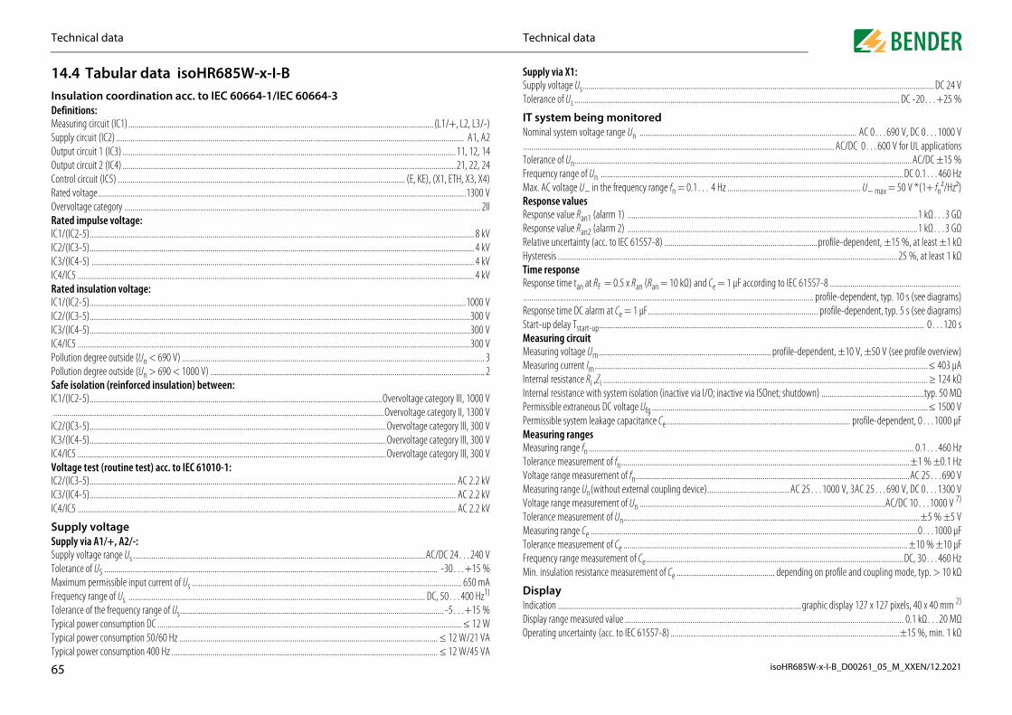
T
isoHR685W-x-I-B_D00261_05_M_XXEN/12.20216
1InDMSuOuOuCoRaOvRaICICICICRaICICICICPoPoSaIC..
ICICICVoICICIC
SSuSuToMFrToTyTyTy
....................................................................................................................................... DC 24 V
...................................................................................................................... DC -20…+25 %
................................................................................................. AC 0…690 V, DC 0…1000 V
...................................................................................... AC/DC 0…600 V for UL applications
............................................................................................................................AC/DC ±15 %
........................................................................................................................DC 0.1…460 Hzge fn = 0.1… 4 Hz ................................................................. U~ max = 50 V *(1+ fn²/Hz²)
...............................................................................................................................1 kΩ…3 GΩ
...............................................................................................................................1 kΩ…3 GΩ) ...........................................................................profile-dependent, ±15 %, at least ±1 kΩ..................................................................................................................... 25 %, at least 1 kΩ
= 10 kΩ) and Ce = 1 μF according to IEC 61557-8 ............................................................................................................................................ profile-dependent, typ. 10 s (see diagrams).............................................................................. profile-dependent, typ. 5 s (see diagrams).................................................................................................................................. 0…120 s
....................................................... profile-dependent, ±10 V, ±50 V (see profile overview)
....................................................................................................................................≤ 403 μA
....................................................................................................................................≥ 124 kΩ(inactive via I/O; inactive via ISOnet; shutdown) ..................................................typ. 50 MΩ....................................................................................................................................≤ 1500 VCe.......................................................................................... profile-dependent, 0…1000 μF
............................................................................................................................. 0.1…460 Hz
...........................................................................................................................±1 % ±0.1 Hz
...........................................................................................................................AC 25…690 Vupling device)........................................ AC 25…1000 V, 3AC 25…690 V, DC 0…1300 V
Voltage range measurement of Un ........................................................................................................................AC/DC 10…1000 V 7)
........................................................................................................................±5 % ±5 V
.......................................................................................................................0…1000 μF
.................................................................................................................. ±10 % ±10 μF
................................................................................................................DC, 30…460 Hz................................................ depending on profile and coupling mode, typ. > 10 kΩ
..............................................................graphic display 127 x 127 pixels, 40 x 40 mm 2)
................................................................................................................ 0.1 kΩ…20 MΩ
..............................................................................................................±15 %, min. 1 kΩ
5
4/IC5 ......................................................................................................................................................................................... AC 2.2 kV
upply voltagepply via A1/+, A2/-:pply voltage range Us ...............................................................................................................................................AC/DC 24…240 Vlerance of US ................................................................................................................................................................... -30…+15 %aximum permissible input current of Us .................................................................................................................................... 650 mAequency range of Us ................................................................................................................................................. DC, 50…400 Hz1)
lerance of the frequency range of Us................................................................................................................................. -5…+15 %pical power consumption DC .....................................................................................................................................................≤ 12 Wpical power consumption 50/60 Hz .............................................................................................................................. ≤ 12 W/21 VApical power consumption 400 Hz .................................................................................................................................. ≤ 12 W/45 VA
Tolerance measurement of Un.........................Measuring range Ce .........................................Tolerance measurement of Ce .........................Frequency range measurement of Ce..............Min. insulation resistance measurement of Ce
DisplayIndication .........................................................Display range measured value ........................Operating uncertainty (acc. to IEC 61557-8)..
Technical dataechnical data
4.4 Tabular data isoHR685W-x-I-Bsulation coordination acc. to IEC 60664-1/IEC 60664-3
efinitions:easuring circuit (IC1) ..................................................................................................................................................... (L1/+, L2, L3/-)pply circuit (IC2) .......................................................................................................................................................................... A1, A2tput circuit 1 (IC3) ...................................................................................................................................................................11, 12, 14tput circuit 2 (IC4) ...................................................................................................................................................................21, 22, 24ntrol circuit (IC5) ............................................................................................................................................ (E, KE), (X1, ETH, X3, X4)ted voltage....................................................................................................................................................................................1300 Vervoltage category .............................................................................................................................................................................. 2IIted impulse voltage:
1/(IC2-5)............................................................................................................................................................................................ 8 kV2/(IC3-5)............................................................................................................................................................................................ 4 kV3/(IC4-5) ........................................................................................................................................................................................... 4 kV4/IC5 .................................................................................................................................................................................................. 4 kVted insulation voltage:
1/(IC2-5)........................................................................................................................................................................................1000 V2/(IC3-5)..........................................................................................................................................................................................300 V3/(IC4-5)..........................................................................................................................................................................................300 V4/IC5 ................................................................................................................................................................................................300 Vllution degree outside (Un < 690 V) .................................................................................................................................................... 3llution degree outside (Un > 690 < 1000 V) ...................................................................................................................................... 2fe isolation (reinforced insulation) between:
1/(IC2-5)...............................................................................................................................................Overvoltage category III, 1000 V................................................................................................................................................................Overvoltage category II, 1300 V2/(IC3-5).................................................................................................................................................Overvoltage category III, 300 V3/(IC4-5).................................................................................................................................................Overvoltage category III, 300 V4/IC5 .......................................................................................................................................................Overvoltage category III, 300 V
ltage test (routine test) acc. to IEC 61010-1:2/(IC3-5)................................................................................................................................................................................... AC 2.2 kV3/(IC4-5)................................................................................................................................................................................... AC 2.2 kV
Supply via X1:Supply voltage Us.....................................Tolerance of Us .........................................
IT system being monitoredNominal system voltage range Un ...........................................................................Tolerance of Un.........................................Frequency range of Un ............................Max. AC voltage U~ in the frequency ranResponse valuesResponse value Ran1 (alarm 1) ...............Response value Ran2 (alarm 2) ...............Relative uncertainty (acc. to IEC 61557-8Hysteresis .................................................Time responseResponse time tan at RF = 0.5 x Ran (Ran..................................................................Response time DC alarm at Ce = 1 μF.....Start-up delay Tstart-up.............................Measuring circuitMeasuring voltage Um.............................Measuring current Im...............................Internal resistance Ri ,Zi ...........................Internal resistance with system isolation Permissible extraneous DC voltage Ufg ...Permissible system leakage capacitance Measuring rangesMeasuring range fn ..................................Tolerance measurement of fn..................Voltage range measurement of fn...........Measuring range Un(without external co
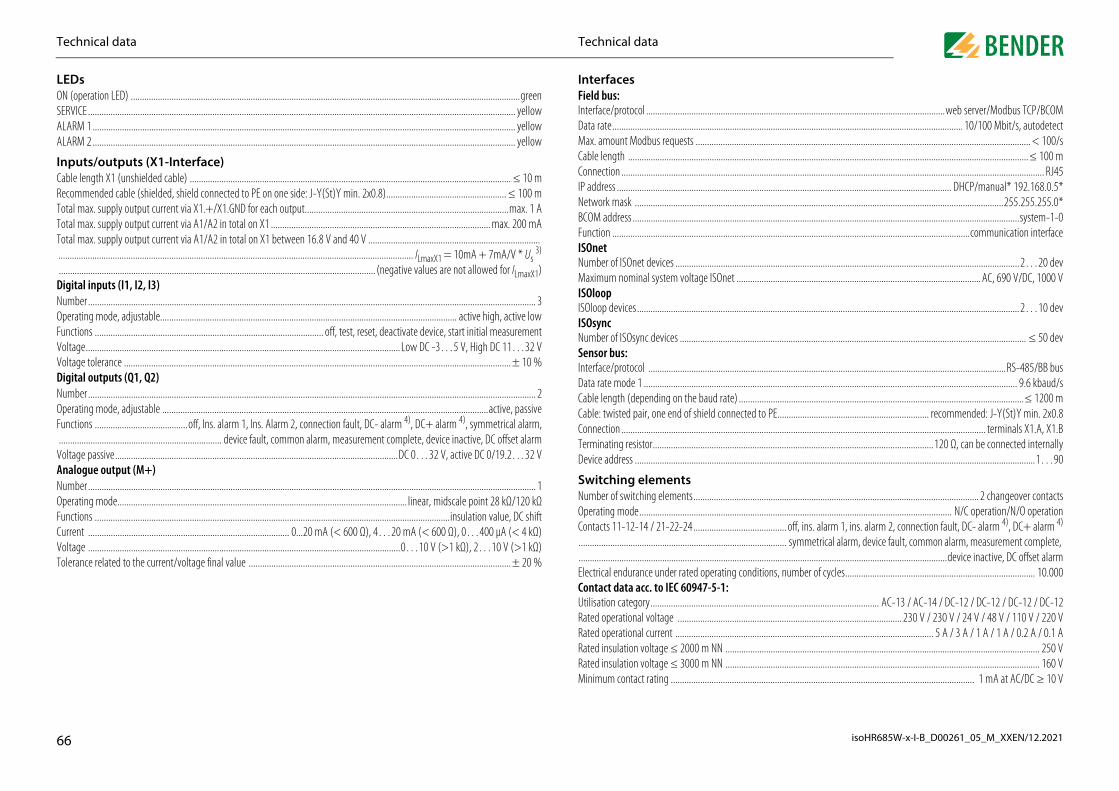
T
isoHR685W-x-I-B_D00261_05_M_XXEN/12.20216
LONSEALAL
InCaReToToTo....
DNuOpFuVoVoDNuOpFu..
VoANuOpFuCuVoTo
...............................................................................................web server/Modbus TCP/BCOM........................................................................................................ 10/100 Mbit/s, autodetect..................................................................................................................................... < 100/s.....................................................................................................................................≤ 100 m............................................................................................................................................ RJ45................................................................................................... DHCP/manual* 192.168.0.5*.........................................................................................................................255.255.255.0*
.................................................................................................................................system-1-0
...........................................................................................................communication interface
.................................................................................................................................2…20 devt ............................................................................................................ AC, 690 V/DC, 1000 V
................................................................................................................................2…10 dev
................................................................................................................................... ≤ 50 dev
..........................................................................................................................RS-485/BB bus
............................................................................................................................... 9.6 kbaud/se) ..............................................................................................................................≤ 1200 mnected to PE................................................................... recommended: J-Y(St)Y min. 2x0.8
.................................................................................................................. terminals X1.A, X1.B..........................................................................................120 Ω, can be connected internally.......................................................................................................................................1…90
.............................................................................................................. 2 changeover contacts................................................................................................... N/C operation/N/O operation......................... off, ins. alarm 1, ins. alarm 2, connection fault, DC- alarm 4), DC+ alarm 4)
.......................... symmetrical alarm, device fault, common alarm, measurement complete, ...................................................................................................................................................................device inactive, DC offset alarm
trical endurance under rated operating conditions, number of cycles.................................................................................... 10.000tact data acc. to IEC 60947-5-1:sation category..................................................................................................... AC-13 / AC-14 / DC-12 / DC-12 / DC-12 / DC-12d operational voltage ................................................................................................... 230 V / 230 V / 24 V / 48 V / 110 V / 220 Vd operational current .................................................................................................................. 5 A / 3 A / 1 A / 1 A / 0.2 A / 0.1 Ad insulation voltage ≤ 2000 m NN ........................................................................................................................................... 250 Vd insulation voltage ≤ 3000 m NN ........................................................................................................................................... 160 Vimum contact rating ...................................................................................................................................... 1 mA at AC/DC ≥ 10 V
6
lerance related to the current/voltage final value ....................................................................................................................± 20 %ElecConUtiliRateRateRateRateMin
Technical dataechnical data
EDs (operation LED) ............................................................................................................................................................................green
RVICE ............................................................................................................................................................................................. yellowARM 1 ........................................................................................................................................................................................... yellowARM 2 ........................................................................................................................................................................................... yellow
puts/outputs (X1-Interface)ble length X1 (unshielded cable) .............................................................................................................................................. ≤ 10 mcommended cable (shielded, shield connected to PE on one side: J-Y(St)Y min. 2x0.8)..................................................... ≤ 100 mtal max. supply output current via X1.+/X1.GND for each output..........................................................................................max. 1 Atal max. supply output current via A1/A2 in total on X1 ................................................................................................. max. 200 mAtal max. supply output current via A1/A2 in total on X1 between 16.8 V and 40 V ....................................................................................................................................................................................................................................... ILmaxX1 = 10mA + 7mA/V * Us
3)
.......................................................................................................................................... (negative values are not allowed for ILmaxX1)igital inputs (I1, I2, I3)
mber ...................................................................................................................................................................................................... 3erating mode, adjustable................................................................................................................................... active high, active lownctions ..................................................................................................... off, test, reset, deactivate device, start initial measurementltage...........................................................................................................................................Low DC -3…5 V, High DC 11…32 Vltage tolerance ...........................................................................................................................................................................± 10 %
igital outputs (Q1, Q2)mber ...................................................................................................................................................................................................... 2erating mode, adjustable ................................................................................................................................................active, passivenctions .........................................off, Ins. alarm 1, Ins. Alarm 2, connection fault, DC- alarm 4), DC+ alarm 4), symmetrical alarm,
...................................................................... device fault, common alarm, measurement complete, device inactive, DC offset alarmltage passive.............................................................................................................................DC 0…32 V, active DC 0/19.2…32 V
nalogue output (M+)mber ...................................................................................................................................................................................................... 1erating mode................................................................................................................................ linear, midscale point 28 kΩ/120 kΩnctions .............................................................................................................................................................insulation value, DC shiftrrent ......................................................................................... 0...20 mA (< 600 Ω), 4…20 mA (< 600 Ω), 0…400 μA (< 4 kΩ)ltage ..........................................................................................................................................0…10 V (>1 kΩ), 2…10 V (>1 kΩ)
InterfacesField bus:Interface/protocol .....................................Data rate...................................................Max. amount Modbus requests ...............Cable length ............................................Connection ...............................................IP address .................................................Network mask ..........................................BCOM address ..........................................Function ...................................................ISOnetNumber of ISOnet devices .......................Maximum nominal system voltage ISOneISOloopISOloop devices.........................................ISOsyncNumber of ISOsync devices ......................Sensor bus:Interface/protocol ....................................Data rate mode 1 ......................................Cable length (depending on the baud ratCable: twisted pair, one end of shield conConnection ...............................................Terminating resistor..................................Device address ..........................................
Switching elementsNumber of switching elements................Operating mode.......................................Contacts 11-12-14 / 21-22-24..................................................................................

echnical dataT
isoHR685W-x-I-B_D00261_05_M_XXEN/12.20216
EEMOpTrLoClStTrLoClStTrLoAr
CCoScNoTiCoStrigfleMMMMPuNoCoStrigid/flexible .......................................................................................................................................................................0.2…2.5 mm²fleMPuNoCoStrigflefle
therperating mode........................................................................................................................................................continuous operationounting position (0°)...........................................................................display-oriented, cooling slots must be ventilated vertically 6)
egree of protection internal components .........................................................................................................................................IP40egree of protection terminals ............................................................................................................................................................IP20IN rail mounting acc. to............................................................................................................................................................ IEC 60715rew fixing...................................................................................................................................................... 3 x M4 with mounting clipclosure material ............................................................................................................................................................... polycarbonate
ammability class .................................................................................................................................................................................V-0NSI code ............................................................................................................................................................................................... 64imensions (W x H x D)............................................................................................................................................... 108 x 93 x 110 mmeight ........................................................................................................................................................................................... < 390 g At a frequency > 200 Hz, the connection of X1 and remote must be insulated. Only permanently installed devices which at leasthave overvoltage category CAT2 (300 V) may be connected.
Indication limited outside the temperature range -25…+55 °C. Us [Volt] = supply voltage ISOMETER® Only for Un ≥ 50 V. This is a class A product. In a domestic environment, this product may cause radio interference. In this case, the user may be re-quired to take corrective actions.
Recommendation: Mounting position 0° (display-oriented, cooling slots must be ventilated vertically).t mounting position 45°, the max. operating temperature is reduced by 10 °C.t mounting position 90°, the max. operating temperature is reduced by 20 °C.
W" option data deviating from the standard versionevices with the suffix "W“ feature increased shock and vibration resistance. The electronics is covered with a special varnish to pro-de increased protection against mechanical stress and moisture. (Refer the following information box)ated operational current switching elements. ........................................................................................max. 3 A (for UL applications)
Combination of ISOMETER® sensor variant with an FP200W:The requirements of the "W" option will only be fulfilled if the ISOMETER® sensor variant is mounted onDIN rail and connected to the FP200W via the patch cable.Refer also to the quick-start guide FP200 (document number D00169).
7
xible with ferrule, with/without plastic sleeve............................................................................................................0.25…2.5 mm²ultiple conductor, flexible with TWIN ferrule with plastic sleeve..................................................................................0.5…1.5 mm²sh-wire terminals X1:minal current................................................................................................................................................................................. ≤ 8 Anductor sizes.........................................................................................................................................................................AWG 24-16
ripping length............................................................................................................................................................................... 10 mmid/flexible .......................................................................................................................................................................0.2…1.5 mm²xible with ferrule without plastic sleeve......................................................................................................................0.25…1.5 mm²xible with TWIN ferrule with plastic sleeve ...............................................................................................................0.25…0.75 mm²
Technical data
nvironment/EMC and temperature ranges C ................................................................................................................................................................................. IEC 61326-2-4 5)
erating temperature........................................................................................................................................................ -25…+55 °Cansport.............................................................................................................................................................................. -40…+85 °Cng-term storage .............................................................................................................................................................. -40…+70 °Cassification of climatic conditions acc. to IEC 60721 (related to temperature and relative humidity)
ationary use (IEC 60721-3-3) ..........................................................................................................................................................3K23ansport (IEC 60721-3-2) .................................................................................................................................................................2K11 ng-term storage (IEC 60721-3-1) ..................................................................................................................................................1K22 assification of mechanical conditions acc. to IEC 60721ationary use (IEC 60721-3-3) .........................................................................................................................................................3M12ansport (IEC 60721-3-2)...................................................................................................................................................................2M4ng-term storage (IEC 60721-3-1) .................................................................................................................................................1M12ea of application ............................................................................................................................................................... ≤ 3000 m NN
onnectionnnection type...................................................................................................pluggable screw-type terminal or push-wire terminalrew-type terminals:minal current............................................................................................................................................................................... ≤ 10 A
ghtening torque.......................................................................................................................................... 0.5…0.6 Nm (5…7 lb-in)nductor sizes.........................................................................................................................................................................AWG 24-12ripping length................................................................................................................................................................................. 7 mmid/flexible .......................................................................................................................................................................0.2…2.5 mm²xible with ferrule, with/without plastic sleeve............................................................................................................0.25…2.5 mm²ultiple conductor, rigid.......................................................................................................................................................0.2…1 mm²ultiple conductor, flexible ...............................................................................................................................................0.2…1.5 mm²ultiple conductor, flexible with ferrule without plastic sleeve .......................................................................................0.25…1 mm²ultiple conductor, flexible with TWIN ferrule with plastic sleeve..................................................................................0.5…1.5 mm²sh-wire terminals:minal current............................................................................................................................................................................... ≤ 10 Anductor sizes.........................................................................................................................................................................AWG 24-12ripping length............................................................................................................................................................................... 10 mm
OOMDDDScEnFlADW1)
2)
3)
4)
5)
6)
AA
"DviR

T
isoHR685W-x-I-B_D00261_05_M_XXEN/12.20216
1T
S N
1
1
1
* included in the scope of delivery**
M
iCi
D
itiiF
components
Type Article No.
ts
20 mA
7204-1421 B9867639604-1421 B9867649620-1421 B986841
ing FP200W B91067904W
24…240 Viso685W-S-I-B B91067125W
8
When using the "transparent front cover 144x72 (IP65)" the cutout in the switchboard cabinet must be extended in height from 66 mm to 68 mm (+ 0.7/-0 mm).
Technical dataechnical data
4.5 Standards and certificationshe ISOMETER® has been developed in compliance with the following standards: • DIN EN 61557-8 (VDE 0413-8): 2015-12 • IEC 61557-8: 2014-12 • IEC 61557-8: 2014/COR1:2016 • DIN EN 61557-8 Cor 1 (VDE 0413-8 Cor 1): 2016-12
ubject to change! The specified standards take into account the edition valid until ovember/21 unless otherwise indicated.
4.6 Ordering details
4.6.1 Device
4.6.2 Accessories
odel Supply voltage US Article No.
so685W-D-I-B AC 24…240 V; 50…400 Hz; DC 24…240 V B91067025Wombination
so685W-S-I-B + FP200W AC 24…240 V; 50…400 Hz; DC 24…240 V B91067225W
escription Article No.
so685 Mechanical accessories comprising: erminal cover and 2 mounting clips*
B91067903
so685 plug kit, screw terminals* B91067901so685 plug kit, with push-wire terminals B91067902ront cover 144x72 transparent (IP65) for FP200 ** B98060005
14.6.3 Suitable system
Description
Suitable measuring instrumenMidscale point: 28 kΩ,120 kΩCurrent values: 0…400 μA, 0…Display for front panel mount
ISOMETER® sensor variantAC 24…240 V; 50…400 Hz; DC

T
isoHR685W-x-I-B_D00261_05_M_XXEN/12.20216
1B
B
B
D
I
I
I
M
MS
S
Wcan be used for reading out measured values and for parameter setting.
Valid from software version Condition / Modifications
D0475 V1.27D0474 V1.26
Editorial revisionInserted- Menu item 'Behaviour when inactive- Menu overview, 2nd menu item = GREEN- Chap. 14.2 Diagrams updated - Contact details relay- UKCA certificate- Change history
9
Technical dataechnical data
4.7 GlossaryB bus The BB bus is an interface which enables Bender devices to communicate
with each other (Bender-internal device bus). The BB bus can be used with an ISOMETER® and one or more EDS44…-S.
COM Protocol for communication between Bender devices via an IP-based network.
S bus The Bender sensor bus is an interface which enables Bender devices to communicate with each other (RS-485 interface).
HCP Dynamic Host Configuration Protocol. It is used to assign the network configuration to Clients via a server.
SOnet Only one ISOMETER® may exist in an isolated system. If several networks monitored by an ISOMETER® are coupled, this function ensures via an Ethernet connection that only one ISOMETER® is actively measuring.
SOnet priority This function makes it possible to give permanent priority to a device in ISOnet mode or to get priority. After 12 hours, the device returns to normal mode.
SOloop Special function for ring systems (all systems are coupled). The ISOloop mode is activated via the information of the dig. input (switch state). If all devices are in this mode, the device with the lowest BCOM address con-tinues to measure.
odbus TCP Modbus is an international widely spread protocol for data transfer via TCP/IP.
odbus RTU Spread protocol for data transfer via RS-485 protocol.ystem (BCOM) The system is the entire installation that is visible for the customer and
defined by the customer. The BCOM communication takes place within this system. Naturally, different systems can exist independently in one network.
ubsystem (BCOM) The subsystem structures parts of the system as units defined by the cus-tomer, e.g. all PQ devices. A typical subsystem are also "non BCOM-capa-ble" devices that are hidden behind a proxy.
ebserver A web server presents the device functions graphically. The web server
14.8 Change log
Date Document-version
12/2021 5

Fotos: Bender Archiv und bendersystembau Archiv.
Field ServiceService-Hotline: 0700-BenderHelp (Telefon und Fax)Carl-Benz-Straße 8 • 35305 Grünberg • Germany
Tel.: +49 6401 807-760Fax: +49 6401 807-629
E-Mail: [email protected]: http://www.bender.de BENDER Group
Bender GmbH & Co. KGPostfach 1161 • 35301 Grünberg • GermanyLondorfer Straße 65 • 35305 Grünberg • Germany
Tel.: +49 6401 807-0Fax: +49 6401 807-259
E-Mail: [email protected]: www.bender.de