Embed Size (px)
Citation preview
The SRXA-60TD10 is isolated dc/dc converter that operates from a
nominal 48 Vdc source. This unit will provide up to 60 W of output power
from a nominal 48 Vdc input. This unit is designed to be highly efficient
and low cost.
Features include remote on/off, over current protection, short circuit
protection, input under-voltage lockout, Pre-bias Start Up and SYNC.
This converter is provided in an industry standard package. Target
applications include computer, networking and telecommunication
industries.
• 36-72VDC Input
• 4.5V/3.0VDC @ 10A Output
• Isolated
• Fixed Frequency (300 kHz)
• High Efficiency
• High Power Density
• Low Cost
• Pre-Bias Start Up
• Input Under Voltage Lockout
• SYNC
• Output Over-voltage shut down
• Over Temperature Protection
• Remote On/Off
• SCP/OCP
• Output Voltage Trim
• Basic Insulation
• TUV certified to EN 60950-1
• UL 60950-1 Recognized
2 SRXA-60TD10
MODEL NUMBER
ACTIVE LOW
OUTPUT
VOLTAGE INPUT VOLTAGE
MAX. OUTPUT
CURRENT
MAX. OUTPUT
POWER TYPICAL EFFICIENCY
SRXA-60TD10 4.5/3.0 Vdc 36Vdc - 72 Vdc 10 A 60 W 88%
NOTE: Add “G” suffix at the end of the model number to indicate Tray Packaging.
S R XA - 60 T D1 0 Y
Mounting Type RoHS
Status
Series
Name
Output
Power
Input
Range
Output
Voltage Active Logic Package Type
Surface mount RoHS 1/4th Brick 60W 36-72V 4.5/3.0Vdc 0 – Active low G – Tray package
PARAMETER DESCRIPTION MIN TYP MAX UNIT
Continuous Input Voltage -0.3 - 75 v
Remote On/Off -0.3 - 15 v
Ambient Temperature -40 - 85 C
Storage Temperature -55 - 130 C
Note: All specifications are typical at 25 C unless otherwise stated.
PARAMETER DESCRIPTION MIN TYP MAX UNIT
Input Voltage Ta min Ta max, Io=0 Io nom 36 48 72 V
Input Current
Vin=36 V
Vin=48 V
Vin=72 V
0.01
0.01
0.01
1.90
1.45
1.00
4.0
3.2
2.2
A
Turn-on Voltage
Threshold - - 32 V
Turn-off Voltage
Threshold
Nominal output voltages guaranteed for 2mS at 48Vdc, 360uF on input
side and maximum capacitive output load 29 - 32 V
Converter 1Start-up Time Worst case condition at Ui min and full load - - 1 S
Rise Time 1 Ui nom, Io=Io nom and both outputs are from 10% to 90% with
maximum capacitive load - - 12 mS
No Load Input Power
(300 kHz)
Io=0, Ui min. Ui max (-40 C-0C) - - 6 W
Io=0, Ui min. Ui max (0C-85C) - - 5 W
Input Voltage Transition
Rate - - 5 V/mS
Inrush Current Transient
Rating Without external capacitance - - 0.01 A2s
Input Fuse (not internally) Fast-acting fuse rated at least for 125 Vdc - - 4 A A
Reflected Ripple Current Vin=48V Io=0 Io nom for each output - - 60 mApp
Note: Measured with the max admissible capacitive load on both outputs.

SRXA-60TD10 3
Asia-Pacific
+86 755 298 85888 Europe, Middle East
+353 61 225 977 North America
+1 408 785 5200
© 2018 Bel Power Solutions & Protection Rev. AE
PARAMETER DESCRIPTION MIN TYP MAX UNIT
Output Voltage Set Point VO1=4.5 V
VO2=3.0 V Vin=48 V, Io=8 A on each output
4.45
2.97
-
-
4.55
3.03 V
Total Output Voltage
Regulation
VO1=4.5 V
VO2=3.0 V Cross regulation, line, load (0--max), temperature
4.35
2.90
-
-
4.65
3.10 V
Output Current
The two output current may not reach the max at
the same time to ensure the max output power
no more than 60 W
0 8 10 A
Output Current Limit VO1=3.6 V - 5.5 V
VO2=2.2 V - 3.75 V
Output voltage 10% lower than minimum
nominal value
12
12
-
-
15
15 A
Output Over-Votage
Protection 115 - 125 %
Short Circuit Protection Ton
Toff
Exceeding the current limit will activate low
frequency hiccup mode on both the outputs
-
-
-
250
30
- mS
Ripple and Noise (rms) VO1=3.6 V - 5.5 V
VO2=2.2 V - 3.75 V Vin=72 V, 0 to 20 MHz Bandwidth, with a 10 uF
ceramic capacitor at the output
-
-
-
-
30
20 mV
Ripple and Noise (pk-pk) VO1=3.6 V - 5.5 V
VO2=2.2 V - 3.75 V
-
-
-
-
120
100
Output Capacitance 100 - 2000 uF
Overshoot at Turn On - - 5 %
Transient Response
50% ~ 100%
Max Load
Overshoot
VO1=
3.6 V - 5.5 V
VO2=
3.6 V - 5.5 V
di/dt=5 A/us, Vin=48 V, with a 470 uF/6.3 V
electrolytic capacitor at the output
- - 200 mV
Settling Time - - 300 uS
100% ~ 50%
Max Load
Overshoot - - 200 mV
Settling Time - - 300 uS
50% ~ 100%
Max Load
Overshoot - - 200 mV
Settling Time - - 300 uS
100% ~ 50%
Max Load
Overshoot - - 200 mV
Settling Time - - 300 uS
Note: All specifications are typical at nominal input, full load at 25 C unless otherwise stated.
4 SRXA-60TD10
PARAMETER DESCRIPTION MIN TYP MAX UNIT
Input to Each Output Test
Voltage Test duration 1 minute - - 1500 V
Input to Baseplate Test duration 1 minute - - 1500 V
Input to Each Output
Resistance Measured with 500 Vdc - - 10 Mohm
Input to Output Capacitance - - 20 nF
Switching Frequency Ui min. Ui max, Io=0. Io nom 280 300 320 kHz
Efficiency1
Vin=38.4 V - 72 V max load on each output, V1 = 5.2 V, V2 =
3.3 V 86 88 - %
Vin=38.4 V - 72 V max load on each output, V1 = 5.2 V, V2 =
2.5 V 85 87 - %
Output Voltage Trim
Range(VO1) 3.6 - 5.5 V
Output Voltage Trim
Range(VO2) 2.2 - 3.75 V
Over Temperature Protection - 115 - ℃
Life Time 20 - - years
Dimensions
Inches (L × W × H)
Millimeters (L × W × H)
2.3 x 1.5 x 0.48
58.43 x 38.10 x 12.19
Inches
Millimeters
Weight - 43 - g
Notes: 1. The efficiency is measured at switching frequency of 300 kHz.
2. All specifications are typical at nominal input, full load at 25 C unless otherwise stated.
PARAMETER DESCRIPTION MIN TYP MAX UNIT
Signal High (Unit Off) Active Low. Remote On/Off pin open, Unit off
2.7 - 15 V
Signal Low (Unit On) -0.3 - 0.8 V

SRXA-60TD10 5
Asia-Pacific
+86 755 298 85888 Europe, Middle East
+353 61 225 977 North America
+1 408 785 5200
© 2018 Bel Power Solutions & Protection Rev. AE
Notes:
1. To trim down the Vout1: a resistor is to be connected between Trim1 and GND in accordance with the following table. To set the
overvoltage protection to 120% of Vout1 the same resistor is to be connected between OV1 and GND.
2. To trim down the Vout2: a resistor is to be connected between Trim2 and GND in accordance with the following table. To set the
overvoltage protection to 120% of Vout2 the same resistor is to be connected between OV2 and GND.

6 SRXA-60TD10
Vo1 Rt1
(Kohm) Vo2
Rt2
(Kohm)
5,50 3,75
5,45 108,000 3,70 73,000
5,40 53,000 3,65 35,500
5,35 34,667 3,60 23,000
5,30 25,500 3,55 16,750
5,25 20,000 3,50 13,000
5,20 16,333 3,45 10,500
5,15 13,714 3,40 8,714
5,10 11,750 3,35 7,375
5,05 10,222 3,30 6,333
5,00 9,000 3,25 5,500
4,95 8,000 3,20 4,818
4,90 7,167 3,15 4,250
4,85 6,462 3,10 3,769
4,80 5,857 3,05 3,357
4,75 5,333 3,00 3,000
4,70 4,875 2,95 2,688
4,65 4,471 2,90 2,412
4,60 4,111 2,85 2,167
4,55 3,789 2,80 1,947
4,50 3,500 2,75 1,750
4,45 3,238 2,70 1,571
4,40 3,000 2,65 1,409
4,35 2,783 2,60 1,261
4,30 2,583 2,55 1,125
4,25 2,400 2,50 1,000
4,20 2,231 2,45 0,885
4,15 2,074 2,40 0,778
4,10 1,929 2,35 0,679
4,05 1,793 2,30 0,586
4,00 1,667 2,25 0,500
3,95 1,548 2,20 0,419
3,90 1,438 - -
3,85 1,333 - -
3,80 1,235 - -
3,75 1,143 - -
3,70 1,056 - -
3,65 0,973 - -
3,60 0,895 - -
SRXA-60TD10 7
Asia-Pacific
+86 755 298 85888 Europe, Middle East
+353 61 225 977 North America
+1 408 785 5200
© 2018 Bel Power Solutions & Protection Rev. AE
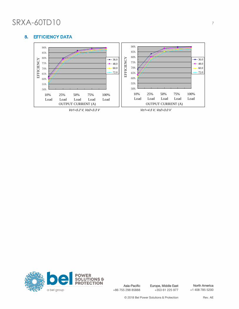
Vo1=5.2 V, Vo2=3.3 V Vo1=4.5 V, Vo2=3.0 V
50%
55%
60%
65%
70%
75%
80%
85%
90%
10%
Load
25%
Load
50%
Load
75%
Load
100%
Load
OUTPUT CURRENT (A)
EF
FIC
IEN
CY 36.0
48.0
60.0
72.0
50%
55%
60%
65%
70%
75%
80%
85%
90%
10%
Load
25%
Load
50%
Load
75%
Load
100%
Load
OUTPUT CURRENT (A)
EF
FIC
IEN
CY
36.0
48.0
60.0
72.0
8 SRXA-60TD10
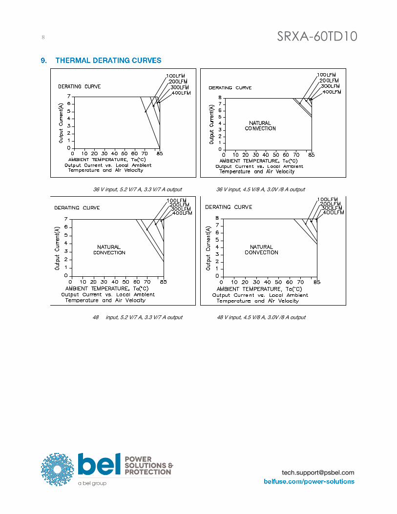
36 V input, 5.2 V/7 A, 3.3 V/7 A output 36 V input, 4.5 V/8 A, 3.0V /8 A output
48 input, 5.2 V/7 A, 3.3 V/7 A output 48 V input, 4.5 V/8 A, 3.0V /8 A output
SRXA-60TD10 9
Asia-Pacific
+86 755 298 85888 Europe, Middle East
+353 61 225 977 North America
+1 408 785 5200
© 2018 Bel Power Solutions & Protection Rev. AE
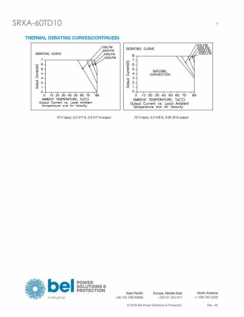
72 V input, 5.2 V/7 A, 3.3 V/7 A output 72 V input, 4.5 V/8 A, 3.0V /8 A output

10 SRXA-60TD10
Vo1=5.2 V 50% to 100% Load (3.5 A-7 A) Transients Vo1=5.2 V 100% to 50% Load (7 A-3.5 A) Transients
Vo2=3.3 V 50% to 100% Load (3.5 A-7 A) Transients Vo2=3.3 V 100% to 50% Load (7 A-3.5 A) Transients

SRXA-60TD10 11
Asia-Pacific
+86 755 298 85888 Europe, Middle East
+353 61 225 977 North America
+1 408 785 5200
© 2018 Bel Power Solutions & Protection Rev. AE
Vo1=4.5 V 50% to 100% Load (4 A-8 A) Transients Vo1=4.5 V 100% to 50% Load (8 A-4 A) Transients
Vo2=3.0 V 50% to 100% Load (4 A-8 A) Transients Vo2=3.0 V 100% to 50% Load (8 A-4 A) Transients
Note: Transient response at di/dt=2.5 A/uS, with external 470 uF electrolytic capacitor.
12 SRXA-60TD10
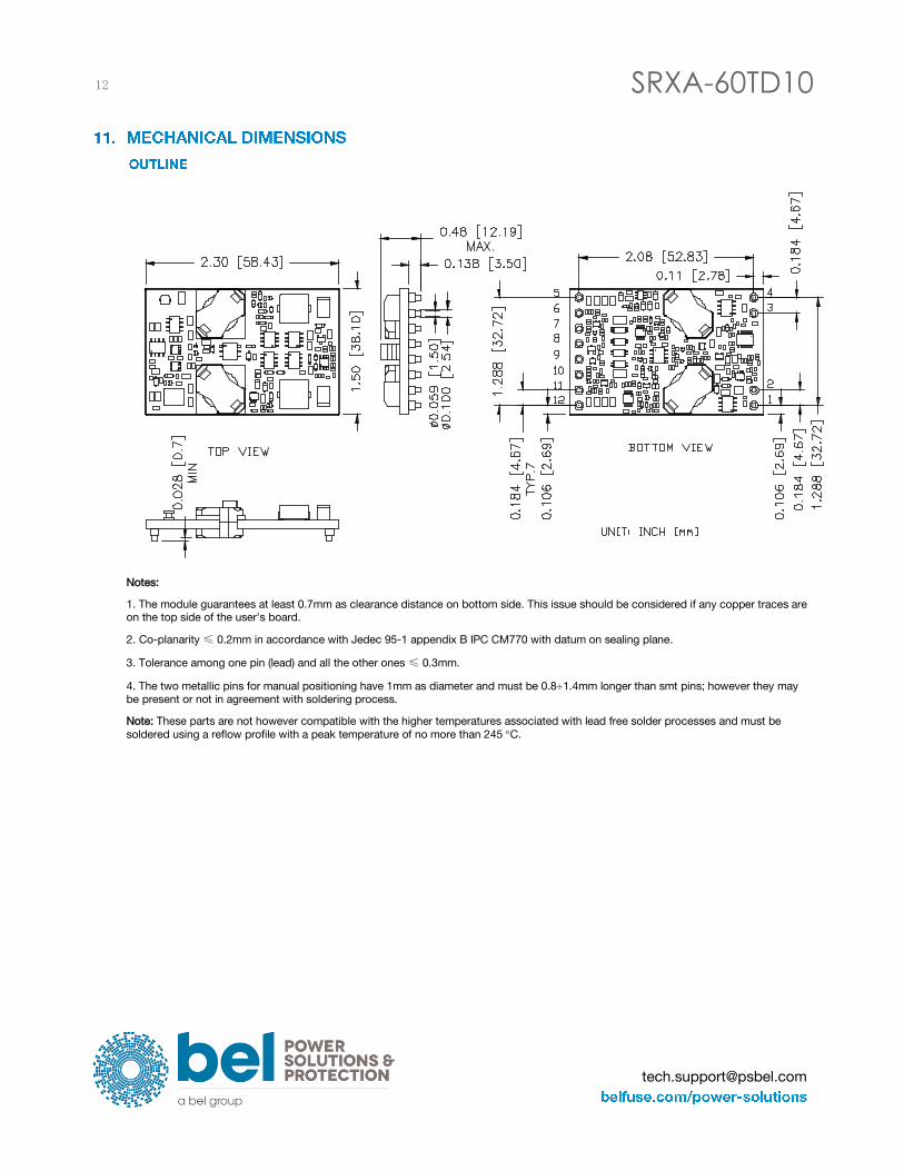
Notes:
1. The module guarantees at least 0.7mm as clearance distance on bottom side. This issue should be considered if any copper traces are
on the top side of the user's board.
2. Co-planarity ≤ 0.2mm in accordance with Jedec 95-1 appendix B IPC CM770 with datum on sealing plane.
3. Tolerance among one pin (lead) and all the other ones ≤ 0.3mm.
4. The two metallic pins for manual positioning have 1mm as diameter and must be 0.81.4mm longer than smt pins; however they may
be present or not in agreement with soldering process.
Note: These parts are not however compatible with the higher temperatures associated with lead free solder processes and must be
soldered using a reflow profile with a peak temperature of no more than 245 C.
SRXA-60TD10 13
Asia-Pacific
+86 755 298 85888 Europe, Middle East
+353 61 225 977 North America
+1 408 785 5200
© 2018 Bel Power Solutions & Protection Rev. AE
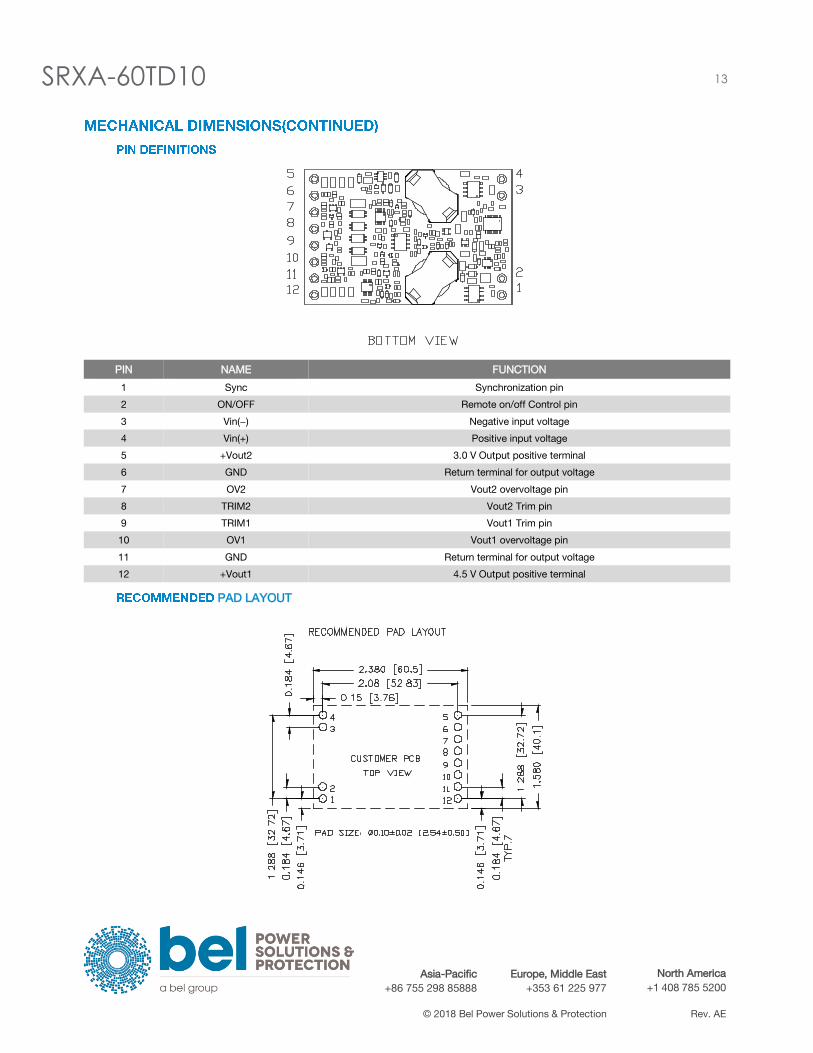
PIN NAME FUNCTION
1 Sync Synchronization pin
2 ON/OFF Remote on/off Control pin
3 Vin(−) Negative input voltage
4 Vin(+) Positive input voltage
5 +Vout2 3.0 V Output positive terminal
6 GND Return terminal for output voltage
7 OV2 Vout2 overvoltage pin
8 TRIM2 Vout2 Trim pin
9 TRIM1 Vout1 Trim pin
10 OV1 Vout1 overvoltage pin
11 GND Return terminal for output voltage
12 +Vout1 4.5 V Output positive terminal
PAD LAYOUT

14 SRXA-60TD10
1) The DC-DC Converter can be operated at an ambient temperature up to 85°C maximum. When installed into final system, the
installation must be in accordance with provided installation instruction and the relevant requirements of EN 60950-1:2001 + A11
and IEC 60950-1:2001.
2) The DC-DC converter is not internal fused, the end user is to provide a maximum normal below 4A fuse in unearthed pin when
install the converter into final system.
3) The creepage distances, clearances and thickness of insulation between unearthed hazardous voltage input and SELV output
circuits have complied with basic insulation requirements according to EN 60950-1:2001 + A11 and IEC 60950-1:2001.
4) The output ratings as shown on the label must not be exceeded.
5) The equipment is to be supplied from a DC source which is separated from AC mains by double or reinforced insulation, or by
basic insulation and suitable earthing providing equivalent protection.
6) The equipment is intended to be installed into a class I or Class II system, suitable external protection devices have to provided
in the final system. Protective earth has to be reliably identified and if equipment is to be installed into Class I system.
7) The equipment shall be installed with an external cooling condition; typical cooling conditions are given in derating for reference.
The airflow direction is towards the side of the equipment.
SRXA-60TD10 15
Asia-Pacific
+86 755 298 85888 Europe, Middle East
+353 61 225 977 North America
+1 408 785 5200
© 2018 Bel Power Solutions & Protection Rev. AE
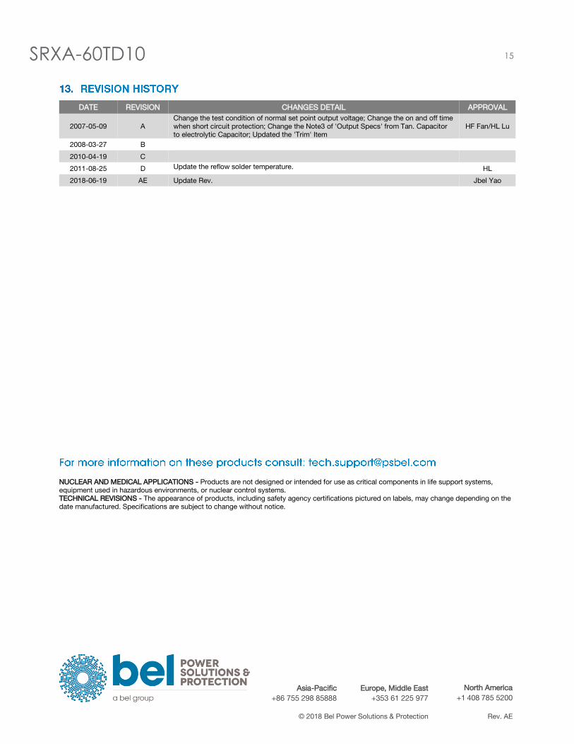
DATE REVISION CHANGES DETAIL APPROVAL
2007-05-09 A
Change the test condition of normal set point output voltage; Change the on and off time
when short circuit protection; Change the Note3 of 'Output Specs' from Tan. Capacitor
to electrolytic Capacitor; Updated the 'Trim' Item
HF Fan/HL Lu
2008-03-27 B
2010-04-19 C
2011-08-25 D Update the reflow solder temperature. HL
2018-06-19 AE Update Rev. Jbel Yao
NUCLEAR AND MEDICAL APPLICATIONS - Products are not designed or intended for use as critical components in life support systems,
equipment used in hazardous environments, or nuclear control systems.
TECHNICAL REVISIONS - The appearance of products, including safety agency certifications pictured on labels, may change depending on the
date manufactured. Specifications are subject to change without notice.