Embed Size (px)
Citation preview

ISO/IEC ISO/IEC 14496-3 Subpart 1:1998
MPEG-4 Audio FCD Subpart 1/ 15:47 / 98-05-27 1
ISO/JTC 1/SC 29 N2203Date: 1998-05-15
ISO/IEC FCD 14496-3 Subpart 1
ISO/JTC 1/SC 29/WG11
Secretariat:
Information Technology - Very Low Bitrate Audio-VisualCoding
Part 3: Audio
Subpart 1: Main Document
Authors: B. Grill, B. Edler, R. Funken, M. Hahn, K. Iijima, N. Iwakami, Y.Lee, T. Moryia, J. Ostermann, S. Nakajima, M. Nishiguchi, T.Nomura, W. Oomen, H. Purnhagen, E. Scheirer, N. Tanaka, A.P.Tan, R. Taori,MPEG-2 AAC Authors (IS -13818-7)
Document type: International standardDocument:sub-type if applicableDocument:stage (20) PréparationDocument:language E
C:\ISOST18\BASICEN.DOT ISOSTD Basic Version 1.8 1996-10-30
ISO/IEC 14496-3:1998 FCD(E) ISO/IEC
2 MPEG-4 Audio FCD / 15:47 / 98-05-27
Organisation of the document
MPEG-4 Audio comprises 6 subparts:
Subpart 1: Main
Subpart 2: Parametric Coding
Subpart 3: CELP Coding
Subpart 4: Time/Frequency Coding
Subpart 5: Structured Audio
Subpart 6: Text to Speech
For reasons of managability of large documents, the CD is divided in several files:
1. w2203: The master file, containing general introduction and description of tools for other functionalities (this file)
2. w2203par: Contains the description of Subpart 2.
3. w2203cel: Contains the description of Subpart 3.
4. w2203tft: Contains the tool descriptions of Subpart 4.
5. w2203tfs: Contains the syntax part of Subpart 4.
6. w2203tfa: Contains the informative part of Subpart 4.
7. w2203sa: Contains the description of Subpart 5.
8. w2203tts: Contains the description of Subpart 6.
For each of the five coding schemes as well as for the tools for other functionalities, there is a sectioncontaining a normative part (description of the syntax and the decoding process) and an informativeannex with encoder and interface description. In addition there are two files containing very largetables. These are:
w2203tvq Twin-VQ vector quantizer tables (Subpart 4).
w2203pvq Parametric coder vector quantizer tables (Subpart 2).
1 INTRODUCTION 3
1.1 Glossary 4
1.2 Symbols and abbreviations 81.2.1 Arithmetic operators 81.2.2 Logical operators 91.2.3 Relational operators 91.2.4 Bitwise operators 91.2.5 Assignment 91.2.6 Mnemonics 91.2.7 Constants 9
1.3 Method of describing bit stream syntax 10
2 TECHNICAL OVERVIEW 11

ISO/IEC ISO/IEC 14496-3 Subpart 1:1998
MPEG-4 Audio FCD Subpart 1/ 15:47 / 98-05-27 3
2.1 MPEG-4 Audio Object Profiles and Levels 112.1.1 Object Profiles 112.1.2 Combination Profiles 122.1.3 Complexity Units 132.1.4 Levels within the Combination Profiles 14
2.2 Complexity Figures for the Natural Audio Coding Algorithms 15
3 INTERFACE TO MPEG-4 SYSTEMS 15
3.1 Syntax 163.1.1 Audio DecoderSpecificInfo 163.1.2 ParametricSpecificConfig 163.1.3 CelpSpecificConfig 163.1.4 TFSpecificConfig 163.1.5 StructuredAudioSpecificConfig 163.1.6 TTSSpecificConfig 163.1.7 Payloads 17
3.2 Semantics 173.2.1 objectProfile 173.2.2 SamplingFrequencyIndex 173.2.3 channelConfiguration 17
4 TOOLS FOR OTHER FUNCTIONALITIES 18
4.1 Speed change 194.1.1 Tool description 194.1.2 Definitions 194.1.3 Speed control process 19
1 PICOLA FUNCTIONAL INTERFACE DESCRIPTION 22
2 PATENT STATEMENTS 23
ISO/IEC 14496-3:1998 FCD(E) ISO/IEC
4 MPEG-4 Audio FCD / 15:47 / 98-05-27
1 IntroductionMPEG-4 audio coding integrates the worlds of speech and high quality audio coding as well as theworlds of sound synthesis and the representation of natural audio. The sound synthetis part iscomprised of tools for the realisation of symbolically defined music and speech. This includes MIDIand Text-to-Speech systems. Furthermore, tools for effects processing and 3-D localisation of soundare included, allowing the creation of artificial sound environments using artificial and naturalsources.
Synthetic audio is described by first defining a set of ‘instrument’ modules that can create and processaudio signals under the control of a script or score file. An instrument is a small network of signalprocessing primitives that can emulate the effects of a natural acoustic instrument. A script or score isa time-sequenced set of commands that invokes various instruments at specific times to contributetheir output to an overall music performance. Other instruments, serving the function of effectsprocessors (reverberators, spatialisers, mixers), can be similarly invoked to receive and process theoutputs of the performing instruments. These actions can not only realise a music composition butcan also organise any other kind of audio, such as speech, sound effects and general ambience.Likewise, the audio sources can themselves be natural sounds, perhaps emanating from an audiochannel decoder, thus enabling synthetic and natural sources to be merged with complete timingaccuracy.
TTS is becoming a rather common interface and plays an important role in various multi-mediaapplication areas. For instance, by using TTS functionality, multi-media contents with narration canbe easily composed without recording natural speech sound. Moreover, TTS with FA/AP/MPfunctionality would possibly make the contents much richer. In MPEG-4 activity, common interfacesfor TTS and TTS for FA/AP/MP are proposed. The proposed MPEG-4 TTS functionality;Hybrid/Multi-Level Scalable TTS, can be considered as a superset of the conventional TTSframework. This extended TTS can utilize prosodic information of natural speech in addition to inputtexts and can generate much higher quality of synthetic speech. The interface and its bitstream formatis strongly scalable; for example, if some parameters of prosodic information are not available, it thengenerates the missing parameters by rule. Still the basic idea for the scalable MPEG-4 TTS interfaceis it can fully utilize all the provided information according to the level of user’s requirements. Thefunctionality of this extended TTS thus ranges from conventional TTS to natural speech coding andits application areas, from simple TTS to AP with TTS and MP dubbing with TTS.
MPEG-4 standardises natural audio coding at bitrates ranging from 2 kbit/s up to 64 kbit/s. Thepresence of the MPEG-2 AAC standard within the MPEG-4 tool set will provide for compression ofgeneral audio. For the bitrates from 2 kbit/s up to 64 kbit/s, the MPEG-4 standard normalises thebitstream syntax and decoding processes in terms of a set of tools. In order to achieve the highestaudio quality within the full range of bitrates and at the same time provide the extra functionalities,three types of coder have been defined. The lowest bitrate range between about 2 and 6 kbit/s, mostlyused for speech coding at 8 kHz sampling frequency, is covered by parametric coding techniques.Coding at the medium bitrates between about 6 and 24 kbit/s uses Code Excited Linear Predictive(CELP) coding techniques. In this region, two sampling rates, 8 and 16 kHz, are used to support abroader range of audio signals (other than speech). For the bitrates typically starting at about 16kbit/s, time to frequency coding techniques are applied. The audio signals in this region typically havebandwidths starting at 8 kHz.
A number of functionalities are provided to facilitate a wide variety of applications which could rangefrom intelligible speech to high quality multichannel audio. Examples of the functionalities are speedcontrol, pitch change, error resilience and scalability in terms of bitrate, bandwidth, error robustness,complexity, etc. as defined below. These functionalities are applicable to the individual codingschemes (parametric, CELP and t/f) as well as across the coding schemes.
• The speed change functionality allows the change of the time scale without altering the pitchduring the decoding process. This can, for example, be used to implement a “fast forward”function (data base search) or to adapt the length of an audio sequence to a given video sequence.
• The pitch change functionality allows the change of the pitch without altering the time scaleduring the encoding or decoding process.This can be used for example for voice alteration orKaraoke type applications.

ISO/IEC ISO/IEC 14496-3 Subpart 1:1998
MPEG-4 Audio FCD Subpart 1/ 15:47 / 98-05-27 5
Bitrate scalability allows a bitstream to be parsed into a bitstream of lower bitrate such that thecombination can still be decoded into a meaningful signal. The bit stream parsing can occur eitherduring transmission or in the decoder.
• Bandwidth scalability is a particular case of bitrate scalability, whereby part of a bitstreamrepresenting a part of the frequency spectrum can be discarded during transmission or decoding.
• Encoder complexity scalability allows encoders of different complexity to generate valid andmeaningful bitstreams.
• Decoder complexity scalability allows a given bitstream to be decoded by decoders of differentlevels of complexity. The audio quality, in general, is related to the complexity of the encoder anddecoder used.
• Error robustness provides the ability for a decoder to avoid or conceal audible distortion caused bytransmission errors.
To allow for smooth transitions between the bitrates and to allow for bitrate and bandwidth scalability,a general framework has been defined. This is illustrated in figure 1.
Satellite UMTS, Cellular DAM, Internet DCME ISDNSecure com.
2 4 6 8 10 12 14 16 24 32 48 64
Parametriccoder
CELP coder
4 kHz 8 kHz 20 kHztypical Audio
Bandwidth
bit-rate (kbps)
T/F coder
Scalable Coder
Figure 1
Starting with a coder operating at a low bitrate, by adding enhancements both the coding quality aswell as the audio bandwidth can be improved. These enhancements are realised within a single coderor alternatively by combining different techniques.
Additional functionalities are realised both within individual coders, and by means of additional toolsaround the coders. An example of a functionality within an individual coder is pitch change withinthe parametric coder.

ISO/IEC 14496-3:1998 FCD(E) ISO/IEC
6 MPEG-4 Audio FCD / 15:47 / 98-05-27
1.1 GlossaryFor the purposes of this International Draft Standard, the following definitions apply. If specific to apart, this is noted in square brackets.
1. alias: Mirrored signal component resulting from sampling.
2. analysis filterbank: Filterbank in the encoder that transforms a broadband PCM audio signal intoa set of spectral coefficients.
3. ancillary data: Part of the bitstream that might be used for transmission of ancillary data.
4. audio buffer: A buffer in the system target decoder (see ISO/IEC 13818-1) for storage ofcompressed audio data.
5. Bark: The Bark is the standard unit corresponding to one critical band width of human hearing.
6. backward compatibility: A newer coding standard is backward compatible with an older codingstandard if decoders designed to operate with the older coding standard are able to continue to operateby decoding all or part of a bitstream produced according to the newer coding standard.
7. bitrate: The rate at which the compressed bitstream is delivered to the input of a decoder.
8. bitstream; stream: An ordered series of bits that forms the coded representation of the data.
9. bitstream verifier: A process by which it is possible to test and verify that all the requirementsspecified in ISO/IEC 13818-7 are met by the bitstream.
10. block companding: Normalising of the digital representation of an audio signal within a certaintime period.
11. byte aligned: A bit in a coded bitstream is byte-aligned if its position is a multiple of 8-bits fromeither the first bit in the stream for the Audio_Data_Interchange_Format (see 1.1) or the first bit inthe syncword for the Audio_Data_Transport_Stream Format (see 1.2).
12. byte: Sequence of 8-bits.
13. centre channel: An audio presentation channel used to stabilise the central component of thefrontal stereo image.
14. channel: A sequence of data representing an audio signal intended to be reproduced at onelistening position.
15. coded audio bitstream: A coded representation of an audio signal.
16. coded representation: A data element as represented in its encoded form.
17. compression: Reduction in the number of bits used to represent an item of data.
18. constant bitrate: Operation where the bitrate is constant from start to finish of the codedbitstream.
19. CRC: The Cyclic Redundancy Check to verify the correctness of data.
20. critical band: This unit of bandwidth represents the standard unit of bandwidth expressed inhuman auditory terms, corresponding to a fixed length on the human cochlea. It is approximatelyequal to 100 Hz at low frequencies and 1/3 octave at higher frequencies, above approximately 700 Hz.
21. data element: An item of data as represented before encoding and after decoding.
22. de-emphasis: Filtering applied to an audio signal after storage or transmission to undo a lineardistortion due to emphasis.
23. decoded stream: The decoded reconstruction of a compressed bitstream.
24. decoder: An embodiment of a decoding process.
25. decoding (process): The process defined in ISO/IEC 13818 part 7 that reads an input codedbitstream and outputs decoded audio samples.
26. digital storage media; DSM: A digital storage or transmission device or system.

ISO/IEC ISO/IEC 14496-3 Subpart 1:1998
MPEG-4 Audio FCD Subpart 1/ 15:47 / 98-05-27 7
27. discrete cosine transform; DCT: Either the forward discrete cosine transform or the inversediscrete cosine transform. The DCT is an invertible, discrete orthogonal transformation.
28. downmix: A matrixing of n channels to obtain less than n channels.
29. editing: The process by which one or more coded bitstreams are manipulated to produce a newcoded bitstream. Conforming edited bitstreams must meet the requirements defined in part 7 ofISO/IEC 13818.
30. emphasis: Filtering applied to an audio signal before storage or transmission to improve thesignal-to-noise ratio at high frequencies.
31. encoder: An embodiment of an encoding process.
32. encoding (process): A process, not specified in ISO/IEC 13818, that reads a stream of input audiosamples and produces a valid coded bitstream as defined in part 7 of ISO/IEC 13818.
33. entropy coding: Variable length lossless coding of the digital representation of a signal to reducestatistical redundancy.
34. FFT: Fast Fourier Transformation. A fast algorithm for performing a discrete Fourier transform(an orthogonal transform).
35. filterbank: A set of band-pass filters covering the entire audio frequency range.
36. flag: A variable which can take one of only the two values defined in this specification.
37. forward compatibility: A newer coding standard is forward compatible with an older codingstandard if decoders designed to operate with the newer coding standard are able to decode bitstreamsof the older coding standard.
38. Fs: Sampling frequency.
39. Hann window: A time function applied sample-by-sample to a block of audio samples beforeFourier transformation.
40. Huffman coding: A specific method for entropy coding.
41. hybrid filterbank: A serial combination of subband filterbank and MDCT.
42. IDCT: Inverse Discrete Cosine Transform.
43. IMDCT: Inverse Modified Discrete Cosine Transform.
44. intensity stereo: A method of exploiting stereo irrelevance or redundancy in stereophonic audioprogrammes based on retaining at high frequencies only the energy envelope of the right and leftchannels.
45. joint stereo coding: Any method that exploits stereophonic irrelevance or stereophonicredundancy.
46. joint stereo mode: A mode of the audio coding algorithm using joint stereo coding.
47. low frequency enhancement (LFE) channel: A limited bandwidth channel for low frequencyaudio effects in a multichannel system.
48. main audio channels: All single_channel_elements (see clause 3.2.1) or channel_pair_elements(see clause 3.2.1) in one program.
49. mapping: Conversion of an audio signal from time to frequency domain by subband filteringand/or by MDCT.
50. masking: A property of the human auditory system by which an audio signal cannot be perceivedin the presence of another audio signal.
51. masking threshold: A function in frequency and time below which an audio signal cannot beperceived by the human auditory system.
52. modified discrete cosine transform (MDCT): A transform which has the property of timedomain aliasing cancellation. An analytical espression for the MDCT can be found in clauseB 2.3.1.2.

ISO/IEC 14496-3:1998 FCD(E) ISO/IEC
8 MPEG-4 Audio FCD / 15:47 / 98-05-27
53. M/S stereo: A method of removing imaging artefacts as well as exploiting stereo irrelevance orredundancy in stereophonic audio programmes based on coding the sum and difference signal insteadof the left and right channels.
54. multichannel: A combination of audio channels used to create a spatial sound field.
55. multilingual: A presentation of dialogue in more than one language.
56. non-tonal component: A noise-like component of an audio signal.
57. Nyquist sampling: Sampling at or above twice the maximum bandwidth of a signal.
58. padding: A method to adjust the average length of an audio frame in time to the duration of thecorresponding PCM samples, by conditionally adding a slot to the audio frame.
59. parameter: A variable within the syntax of this specification which may take one of a range ofvalues. A variable which can take one of only two values is a flag or indicator and not a parameter.
60. parser: Functional stage of a decoder which extracts from a coded bitstream a series of bitsrepresenting coded elements.
61. polyphase filterbank: A set of equal bandwidth filters with special phase interrelationships,allowing for an efficient implementation of the filterbank.
62. prediction error: The difference between the actual value of a sample or data element and itspredictor.
63. prediction: The use of a predictor to provide an estimate of the sample value or data elementcurrently being decoded.
64. predictor: A linear combination of previously decoded sample values or data elements.
65. presentation channel: An audio channel at the output of the decoder.
66. program: A set of main audio channels, coupling_channel_elements (see clause 3.2.1),lfe_channel_elements (see clause 3.2.1), and associated data streams intended to be decoded andplayed back simultaneously A program may be defined by default (see clause 3.5.1) or specifically bya program_configuration_element (see clause 3.2.1). A given single_channel_element (see clause3.2.1) , channel_pair_element (see clause 3.2.1), coupling_channel_element, lfe_channel_element ordata channel may accompany one or more programs in any given bitstream..
67. psychoacoustic model: A mathematical model of the masking behaviour of the human auditorysystem.
68. random access: The process of beginning to read and decode the coded bitstream at an arbitrarypoint.
69. reserved: The term "reserved" when used in the clauses defining the coded bitstream indicatesthat the value may be used in the future for ISO/IEC defined extensions.
70. Sampling Frequency (Fs): Defines the rate in Hertz which is used to digitise an audio signalduring the sampling process.
71. scalefactor: Factor by which a set of values is scaled before quantization.
72. scalefactor band: A set of spectral coefficients which are scaled by one scalefactor.
73. scalefactor index: A numerical code for a scalefactor.
74. side information: Information in the bitstream necessary for controlling the decoder.
75.spectral coefficients: Discrete frequency domain data output from the analysis filterbank.
76. spreading function: A function that describes the frequency spread of masking effects.
77. stereo-irrelevant: A portion of a stereophonic audio signal which does not contribute to spatialperception.
78. stuffing (bits); stuffing (bytes): Code-words that may be inserted at particular locations in thecoded bitstream that are discarded in the decoding process. Their purpose is to increase the bitrate ofthe stream which would otherwise be lower than the desired bitrate.
ISO/IEC ISO/IEC 14496-3 Subpart 1:1998
MPEG-4 Audio FCD Subpart 1/ 15:47 / 98-05-27 9
79. surround channel: An audio presentation channel added to the front channels (L and R or L, R,and C) to enhance the spatial perception.
80. syncword: A 12-bit code embedded in the audio bitstream that identifies the start of aadts_frame() (see 1.2, Table 6.4).
81. synthesis filterbank: Filterbank in the decoder that reconstructs a PCM audio signal fromsubband samples.
82. tonal component: A sinusoid-like component of an audio signal.
83. variable bitrate: Operation where the bitrate varies with time during the decoding of a codedbitstream.
84. variable length coding: A reversible procedure for coding that assigns shorter code-words tofrequent symbols and longer code-words to less frequent symbols.
85. variable length code (VLC): A code word assigned by variable length encoder (See variablelength coding)
86. variable length decoder: A procedure to obtain the symbols encoded with a variable lengthcoding technique.
87. variable length encoder: A procedure to assign variable length codewords to symbols.
1.2 Symbols and abbreviationsThe mathematical operators used to describe this Recommendation | International Standard aresimilar to those used in the C programming language. However, integer division with truncation androunding are specifically defined. The bitwise operators are defined assuming twos-complementrepresentation of integers. Numbering and counting loops generally begin from zero.
1.2.1 Arithmetic operators
+ Addition.
− Subtraction (as a binary operator) or negation (as a unary operator).
++ Increment.
− − Decrement.
* Multiplication.
^ Power.
/ Integer division with truncation of the result toward zero. For example, 7/4 and −7/−4 aretruncated to 1 and −7/4 and 7/−4 are truncated to −1.
// Integer division with rounding to the nearest integer. Half-integer values are rounded awayfrom zero unless otherwise specified. For example 3//2 is rounded to 2, and −3//2 isrounded to −2.
DIV Integer division with truncation of the result towards −∞.
| | Absolute value. | x | = x when x > 0| x | = 0 when x == 0| x | = −x when x < 0
% Modulus operator. Defined only for positive numbers.
Sign( ) Sign. Sign(x) = 1 when x > 0Sign(x) = 0 when x == 0Sign(x) = −1 when x < 0

ISO/IEC 14496-3:1998 FCD(E) ISO/IEC
10 MPEG-4 Audio FCD / 15:47 / 98-05-27
INT ( ) Truncation to integer operator. Returns the integer part of the real-valued argument.
NINT ( ) Nearest integer operator. Returns the nearest integer value to the real-valued argument.Half-integer values are rounded away from zero.
sin Sine.
cos Cosine.
exp Exponential.
√ Square root.
log10 Logarithm to base ten.
loge Logarithm to base e.
log2 Logarithm to base 2.
1.2.2 Logical operators
|| Logical OR.
&& Logical AND.
! Logical NOT
1.2.3 Relational operators
> Greater than.
>= Greater than or equal to.
< Less than.
<= Less than or equal to.
== Equal to.
!= Not equal to.
max [,...,] the maximum value in the argument list.
min [,...,] the minimum value in the argument list.
1.2.4 Bitwise operators
A twos complement number representation is assumed where the bitwise operators are used.
& AND
| OR
>> Shift right with sign extension.
<< Shift left with zero fill.
1.2.5 Assignment
= Assignment operator.
1.2.6 Mnemonics
The following mnemonics are defined to describe the different data types used in the coded bit stream.
bslbf Bit string, left bit first, where "left" is the order in which bit strings arewritten in ISO/IEC 11172. Bit strings are written as a string of 1s and 0swithin single quote marks, e.g. '1000 0001'. Blanks within a bit string arefor ease of reading and have no significance.
L, C, R, LS, RS Left, center, right, left surround and right surround audio signals

ISO/IEC ISO/IEC 14496-3 Subpart 1:1998
MPEG-4 Audio FCD Subpart 1/ 15:47 / 98-05-27 11
rpchof Remainder polynomial coefficients, highest order first. (Audio)
uimsbf Unsigned integer, most significant bit first.
vlclbf Variable length code, left bit first, where "left" refers to the order in whichthe VLC codes are written.
window Number of the actual time slot in case of block_type==2, 0 <= window <=2. (Audio)
The byte order of multi-byte words is most significant byte first.
1.2.7 Constants
π 3,14159265358...
e 2,71828182845...
1.3 Method of describing bit stream syntaxThe bit stream retrieved by the decoder is described in 1 (Syntax). Each data item in the bit stream isin bold type. It is described by its name, its length in bits, and a mnemonic for its type and order oftransmission.
The action caused by a decoded data element in a bit stream depends on the value of that data elementand on data elements previously decoded. The decoding of the data elements and the definition of thestate variables used in their decoding are described in 3.3.. The following constructs are used toexpress the conditions when data elements are present, and are in normal type:
Note this syntax uses the 'C'-code convention that a variable or expression evaluating to a non-zerovalue is equivalent to a condition that is true.
while ( condition ) {
data_element
. . .
}
If the condition is true, then the group of data elements occurs next in thedata stream. This repeats until the condition is not true.
do {
data_element
. . .
} while ( condition )
The data element always occurs at least once. The data element is repeateduntil the condition is not true.
if ( condition) {
data_element
. . .
}
If the condition is true, then the first group of data elements occurs next inthe data stream
else {
data_element
. . .
}
If the condition is not true, then the second group of data elements occursnext in the data stream.
ISO/IEC 14496-3:1998 FCD(E) ISO/IEC
12 MPEG-4 Audio FCD / 15:47 / 98-05-27
for (expr1; expr2; expr3){
data_element
. . .
}
Expr1 is an expression specifying the initialisation of the loop. Normally itspecifies the initial state of the counter. Expr2 is a condition specifying a testmade before each iteration of the loop. The loop terminates when thecondition is not true. Expr3 is an expression that is performed at the end ofeach iteration of the loop, normally it increments a counter.
Note that the most common usage of this construct is as follows:
for ( i = 0; i < n; i++) {
data_element
. . .
}
The group of data elements occurs n times. Conditional constructs within thegroup of data elements may depend on the value of the loop control variablei, which is set to zero for the first occurrence, incremented to one for thesecond occurrence, and so forth.
As noted, the group of data elements may contain nested conditional constructs. For compactness, the{} may be omitted when only one data element follows.
data_element [ ] data_element [ ] is an array of data. The number of data elements is indicatedby the context.
data_element [n] data_element [n] is the n+1th element of an array of data.
data_element [m][n] data_element [m][n] is the m+1,n+1 th element of a two-dimensional arrayof data.
data_element [l][m][n] data_element [l][m][n] is the l+1,m+1,n+1 th element of a three-dimensionalarray of data.
data_element [m..n] data_element [m..n]is the inclusive range of bits between bit m and bit n inthe data_element.
While the syntax is expressed in procedural terms, it should not be assumed that clause x.x.ximplements a satisfactory decoding procedure. In particular, it defines a correct and error-free inputbit stream. Actual decoders must include a means to look for start codes in order to begin decodingcorrectly.
Definition of bytealigned function
The function bytealigned ( ) returns 1 if the current position is on a byte boundary, that is the next bitin the bit stream is the first bit in a byte. Otherwise it returns 0.
Definition of nextbits function
The function nextbits ( ) permits comparison of a bit string with the next bits to be decoded in the bitstream.
2 Technical Overview
to be added
ISO/IEC ISO/IEC 14496-3 Subpart 1:1998
MPEG-4 Audio FCD Subpart 1/ 15:47 / 98-05-27 13
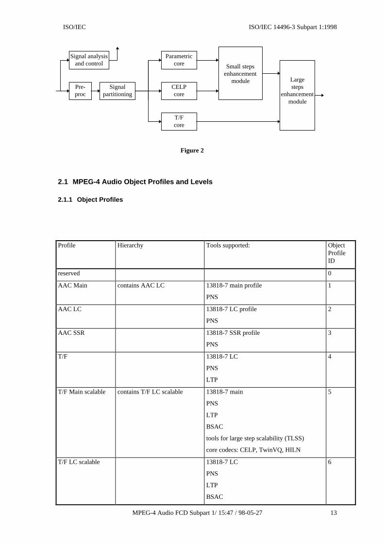
Figure 2
2.1 MPEG-4 Audio Object Profiles and Levels
2.1.1 Object Profiles
Profile Hierarchy Tools supported: ObjectProfileID
reserved 0
AAC Main contains AAC LC 13818-7 main profile
PNS
1
AAC LC 13818-7 LC profile
PNS
2
AAC SSR 13818-7 SSR profile
PNS
3
T/F 13818-7 LC
PNS
LTP
4
T/F Main scalable contains T/F LC scalable 13818-7 main
PNS
LTP
BSAC
tools for large step scalability (TLSS)
core codecs: CELP, TwinVQ, HILN
5
T/F LC scalable 13818-7 LC
PNS
LTP
BSAC
6
Signal analysisand control
Pre-proc
Signalpartitioning
Parametriccore
CELPcore
T/Fcore
Small stepsenhancement
module Largesteps
enhancementmodule

ISO/IEC 14496-3:1998 FCD(E) ISO/IEC
14 MPEG-4 Audio FCD / 15:47 / 98-05-27
tools for large step scalability (TLSS)
core codecs. CELP, TwinVQ, HILN
TwinVQ core TwinVQ 7
CELP CELP 8
HVXC HVXC 9
HILN HILN 10
TTSI Text-To-Speech Interface 11
Main Synthetic contains Wavetable Synthesis all structured audio tools 12
Wavetable Synthesis SASBF
MIDI
13
reserved 14
reserved 15
2.1.2 Combination Profiles
[ make reference to systems 7.3.3.3 DecoderConfigDescriptor, profileAndLevelIndication Values !]
Combination Profile Hierarchy Audio Object Profiles supported:
Main Contains Scalable, Speech andLow Rate Synthetic
AAC Main, LC, SSR
T/F, T/F Main Scalable, T/F LC Scalable
TwinVQ core
CELP
HVXC
HILN
Main Synthetic
TTSI
Scalable Contains Speech T/F LC Scalable
AAC-LC or/and T/F
CELP
HVXC
TwinVQ core
HILN
Wavetable Synthesis
TTSI
Speech CELP
HVXC
TTSI
Low Rate Synthesis Wavetable Synthesis
TTSI

ISO/IEC ISO/IEC 14496-3 Subpart 1:1998
MPEG-4 Audio FCD Subpart 1/ 15:47 / 98-05-27 15
2.1.3 Complexity Units
Complexity units are defined to give an approximation of the decoder complexity in terms ofprocessing power and RAM usage required for processing MPEG-4 Audio bitstreams in dependenceof specific parameters.
The approximated processing power is given in “Processor Complexity Units” (PCU), specified ininteger numbers of MOPS. The approximated RAM usage is given in “RAM Complexity Units”(RCU), specified in (mostly) integer numbers of kWords (1000 words). The RCU numbers do notinclude working buffers which can be shared between different objects and/or channels. Totalcomplexity estimates for single-object / single-channel decoders which also include ROMrequirements are given in Section 2.2.
If a level of a profile is specified by the maximum number of complexity units, a flexible configurationof the decoder handling different types of objects is allowed under the constraint that both values forthe total complexity for decoding and sampling rate conversion (if needed) do not exceed this limit.
The following table gives complexity estimates for the different object profiles:
Object Profile Parameters PCU (MOPS) RCU (kWords) Remarks
AAC Main fs = 48 kHz 5 5 1)
AAC LC fs = 48 kHz 3 3 1)
AAC SSR fs = 48 kHz 4 3 1)
T/F fs = 48 kHz 4 3 1)
T/F Main Scalable fs = 48 kHz 6 5 1), 2)
T/F LC Scalable fs = 48 kHz 5 3 1), 2)
TwinVQ core fs = 24 kHz 2 3 1)
CELP fs = 8 kHz 1 1
CELP fs = 16 kHz 2 1
CELP fs = 8/16 kHz(bandwidth scalable)
4 1
HVXC fs = 8 kHz 2 1
HILN fs = 8 kHz, ns = 40 5 2 1), 3)
HILN fs = 8 kHz, ns = 90 10 2 1), 3)
TTSI - - 4)
Wavetable Synthesis fs= ???, nt = ??? under study under study, 5)
Main Synthetic under study under study
Sampling Rate Conversion rf = 2, 3, 4, 6 2 (.5)
Definitions:
• fs = sampling frequency
• ns = max. number of sinusoids to be synthesized
• nt = max. number of tones to be synthesized simultaneously
• rf = ratio of sampling rates
Notes:

ISO/IEC 14496-3:1998 FCD(E) ISO/IEC
16 MPEG-4 Audio FCD / 15:47 / 98-05-27
1) PCU proportional to sampling frequency
2) Includes core decoder
3) RCU proportional to sampling frequency
4) The complexity for speech synthesis is not taken into account
5) Size of wavetable
2.1.4 Levels within the Combination Profiles
Levels for Main Combination Profile
Four levels are defined by complexity units:
1. PCU < 40, RCU < 20
2. PCU < 80, RCU < 64
3. PCU < 160, RCU < 128
4. PCU < 320, RCU < 64000
Levels for Scalable Combination Profile
Four levels are defined by configuration, the fourth level is defined by complexity units:
1. 24kHz 1 channel or 1 object (all object profiles) or 2 objects (overlay of a speech object and onelow complexity SA or HILN object at 16 kHz)
2. 24kHz 2 channels or 2 objects
3. 48kHz 2 channels or 2 objects (48 kHz t/f or speech coding)
4. 48 kHz/24 kHz 5 channels or multiple objects, max. one integer factor sampling rate conversionfor a maximum of two channels. Flexible configuration is allowed. PCU < 30, RCU < 19.
Levels for Speech Combination Profile
Only one level is defined for one speech object.
Levels for Low Rate Synthesis Combination Profile
Two levels are defined by the maximum number of tones to be synthesized simultaneously, the size ofthe sample RAM and by the maximum number of TTS objects which can be transmitted:
1. max. 8 tones to be synthesized simultaneously, 64 kWords of sample RAMmax. 2 TTS objects
2. max. 24 tones to be synthesized simultaneously, 256 kWords of sample RAMmax. 8 TTS objects
2.2 Complexity Figures for the Natural Audio Coding Algorithms
Overview of the complexity of the MPEG-4 Natural Audio Coding Algorithms
Complexity AAC AAC-LC
BSAC TwinVQ
HILN HVXC NB-CELP
WB-CELP
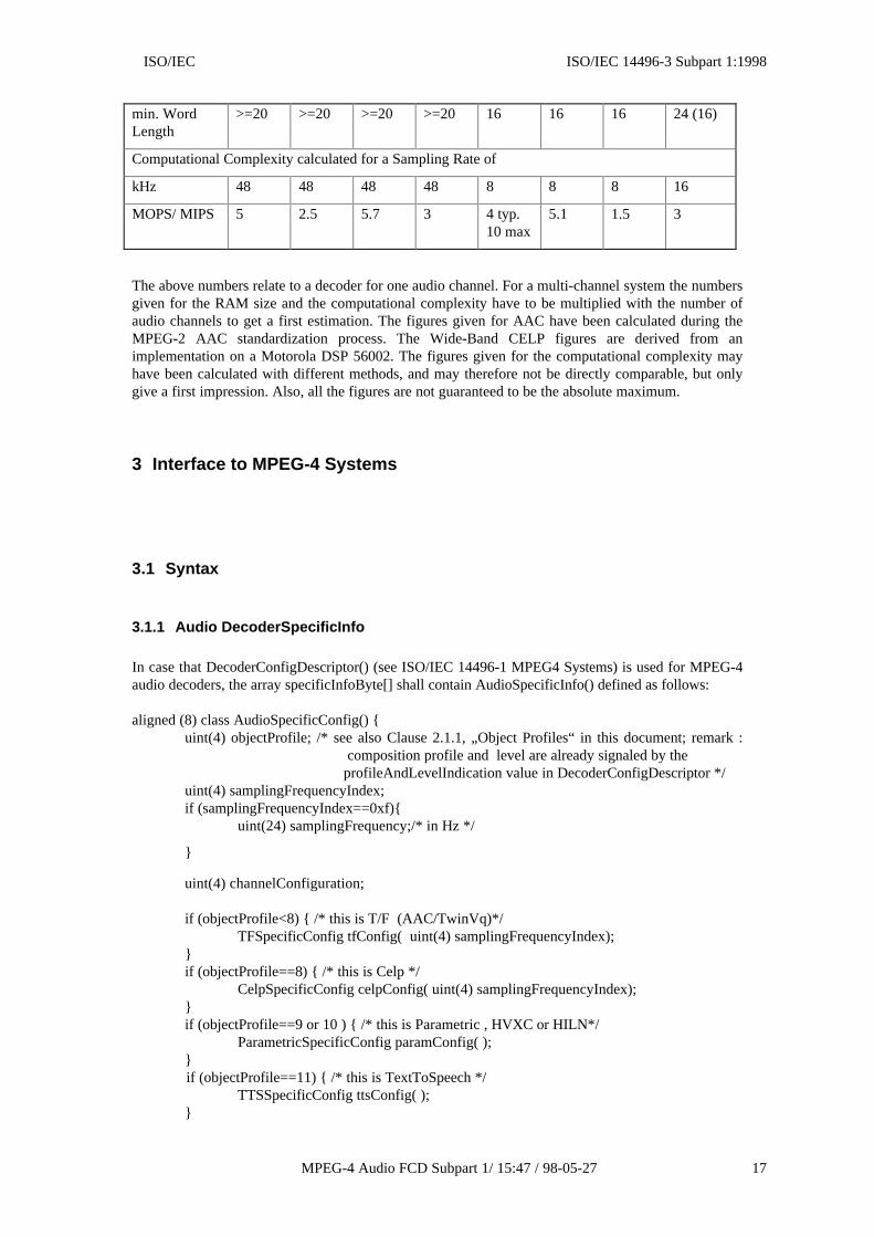
Memory Requirements for 1 Audio Channel and Minimum Word Length
RAM (Words) 4256 2232 4346 4240 3000 1500 650 830
ROM (Words) 3545 3545 3618 43000 4000 7700 2300 1000
ISO/IEC ISO/IEC 14496-3 Subpart 1:1998
MPEG-4 Audio FCD Subpart 1/ 15:47 / 98-05-27 17
min. WordLength
>=20 >=20 >=20 >=20 16 16 16 24 (16)
Computational Complexity calculated for a Sampling Rate of
kHz 48 48 48 48 8 8 8 16
MOPS/ MIPS 5 2.5 5.7 3 4 typ.10 max
5.1 1.5 3
The above numbers relate to a decoder for one audio channel. For a multi-channel system the numbersgiven for the RAM size and the computational complexity have to be multiplied with the number ofaudio channels to get a first estimation. The figures given for AAC have been calculated during theMPEG-2 AAC standardization process. The Wide-Band CELP figures are derived from animplementation on a Motorola DSP 56002. The figures given for the computational complexity mayhave been calculated with different methods, and may therefore not be directly comparable, but onlygive a first impression. Also, all the figures are not guaranteed to be the absolute maximum.
3 Interface to MPEG-4 Systems
3.1 Syntax
3.1.1 Audio DecoderSpecificInfo
In case that DecoderConfigDescriptor() (see ISO/IEC 14496-1 MPEG4 Systems) is used for MPEG-4audio decoders, the array specificInfoByte[] shall contain AudioSpecificInfo() defined as follows:
aligned (8) class AudioSpecificConfig() {uint(4) objectProfile; /* see also Clause 2.1.1, „Object Profiles“ in this document; remark :
composition profile and level are already signaled by theprofileAndLevelIndication value in DecoderConfigDescriptor */
uint(4) samplingFrequencyIndex;if (samplingFrequencyIndex==0xf){
uint(24) samplingFrequency;/* in Hz */
}
uint(4) channelConfiguration;
if (objectProfile<8) { /* this is T/F (AAC/TwinVq)*/TFSpecificConfig tfConfig( uint(4) samplingFrequencyIndex);
}if (objectProfile==8) { /* this is Celp */
CelpSpecificConfig celpConfig( uint(4) samplingFrequencyIndex);}if (objectProfile==9 or 10 ) { /* this is Parametric , HVXC or HILN*/
ParametricSpecificConfig paramConfig( );}
if (objectProfile==11) { /* this is TextToSpeech */TTSSpecificConfig ttsConfig( );
}
ISO/IEC 14496-3:1998 FCD(E) ISO/IEC
18 MPEG-4 Audio FCD / 15:47 / 98-05-27
if (objectProfile==12 or 13) { /* this is structured audio , Main Synthetic or Wavetable Synthesis*/
StructuredAudioSpecificConfig strucConfig( ); }
}
3.1.2 ParametricSpecificConfig
Defined in subpart 2.
3.1.3 CelpSpecificConfig
Defined in subpart 3.
3.1.4 TFSpecificConfig
Defined in subpart 4.
3.1.5 StructuredAudioSpecificConfig
Defined in subpart 5.
3.1.6 TTSSpecificConfig
Defined in subpart 6.
3.1.7 Payloads
The actual payloads for each configuration are defined in the corresponding subparts. These are thebasic entities to be carried by the systems transport layer.
3.2 Semantics
3.2.1 objectProfile
A four bit field indicating the object profile. This is the master switch which selects the actual bitstream syntax of the audio data. In general, different object profiles use a different bit stream syntax.The interpretation of this field is given in the Object Profiles table above.
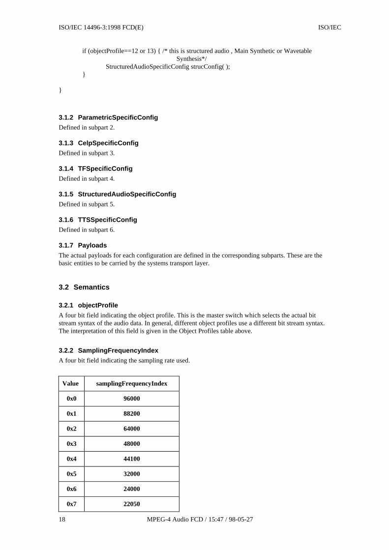
3.2.2 SamplingFrequencyIndex
A four bit field indicating the sampling rate used.
Value samplingFrequencyIndex
0x0 96000
0x1 88200
0x2 64000
0x3 48000
0x4 44100
0x5 32000
0x6 24000
0x7 22050
ISO/IEC ISO/IEC 14496-3 Subpart 1:1998
MPEG-4 Audio FCD Subpart 1/ 15:47 / 98-05-27 19
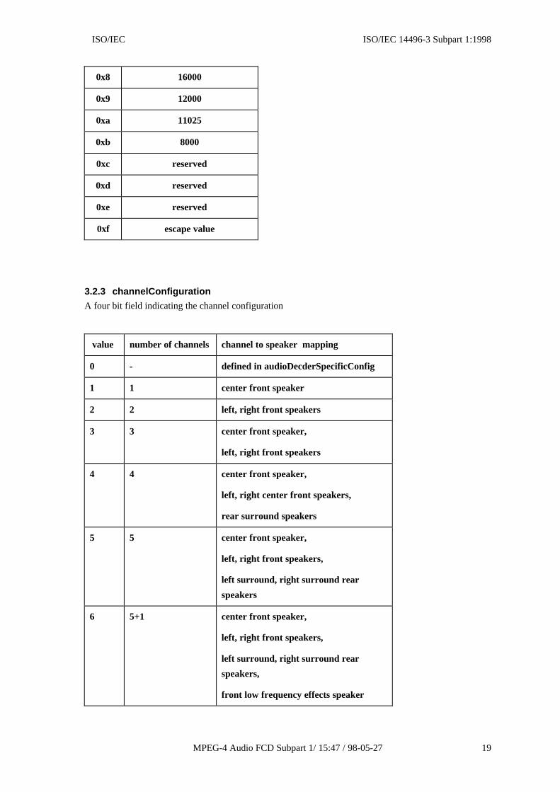
0x8 16000
0x9 12000
0xa 11025
0xb 8000
0xc reserved
0xd reserved
0xe reserved
0xf escape value
3.2.3 channelConfiguration
A four bit field indicating the channel configuration
value number of channels channel to speaker mapping
0 - defined in audioDecderSpecificConfig
1 1 center front speaker
2 2 left, right front speakers
3 3 center front speaker,
left, right front speakers
4 4 center front speaker,
left, right center front speakers,
rear surround speakers
5 5 center front speaker,
left, right front speakers,
left surround, right surround rear
speakers
6 5+1 center front speaker,
left, right front speakers,
left surround, right surround rear
speakers,
front low frequency effects speaker
ISO/IEC 14496-3:1998 FCD(E) ISO/IEC
20 MPEG-4 Audio FCD / 15:47 / 98-05-27
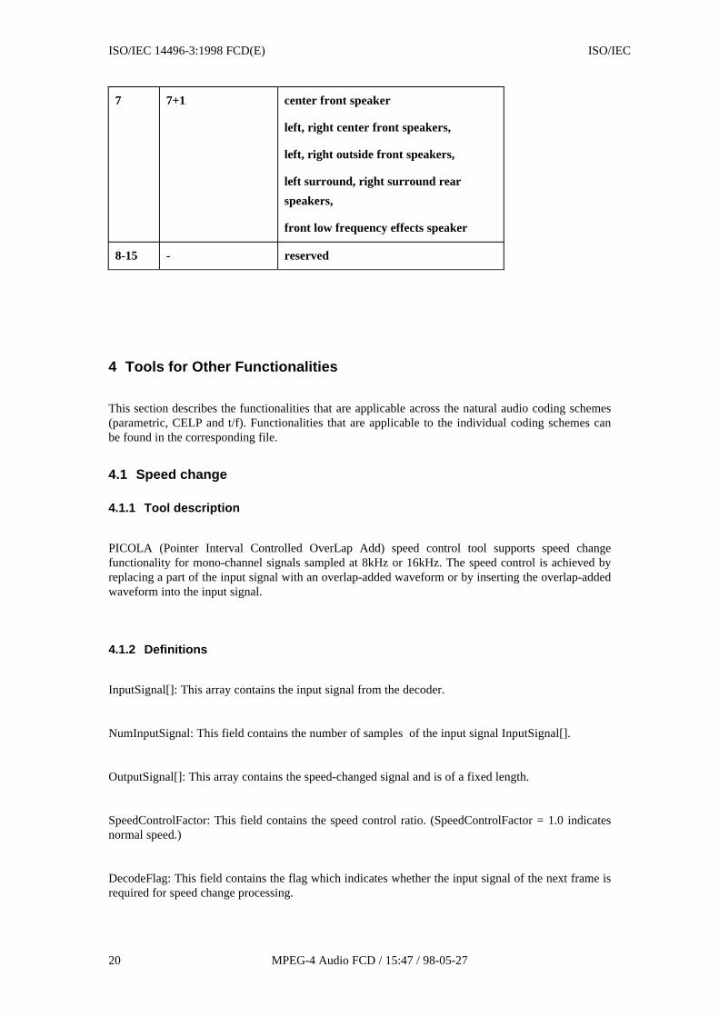
7 7+1 center front speaker
left, right center front speakers,
left, right outside front speakers,
left surround, right surround rear
speakers,
front low frequency effects speaker
8-15 - reserved
4 Tools for Other Functionalities
This section describes the functionalities that are applicable across the natural audio coding schemes(parametric, CELP and t/f). Functionalities that are applicable to the individual coding schemes canbe found in the corresponding file.
4.1 Speed change
4.1.1 Tool description
PICOLA (Pointer Interval Controlled OverLap Add) speed control tool supports speed changefunctionality for mono-channel signals sampled at 8kHz or 16kHz. The speed control is achieved byreplacing a part of the input signal with an overlap-added waveform or by inserting the overlap-addedwaveform into the input signal.
4.1.2 Definitions
InputSignal[]: This array contains the input signal from the decoder.
NumInputSignal: This field contains the number of samples of the input signal InputSignal[].
OutputSignal[]: This array contains the speed-changed signal and is of a fixed length.
SpeedControlFactor: This field contains the speed control ratio. (SpeedControlFactor = 1.0 indicatesnormal speed.)
DecodeFlag: This field contains the flag which indicates whether the input signal of the next frame isrequired for speed change processing.

ISO/IEC ISO/IEC 14496-3 Subpart 1:1998
MPEG-4 Audio FCD Subpart 1/ 15:47 / 98-05-27 21
DecodeFlag Description
0 Input signal of the next frame is not required
1 Input signal of the next frame is required
OutputFlag: This field contains the flag which indicates whether the output array OutputSignal[]contains speed-changed samples, the size of which is less than the fixed output array size, theoutstanding difference being filled by the next speed-changed signal.
OutputFlag Description
0 Speed-changed signal has size less than the fixed-size outputarray
1 Speed-changed signal has size equal to the fixed-size outputarray and therefore be outputted.
4.1.3 Speed control process
The block diagram of the speed controller is shown in Figure 1. The input signal InputSignal[], whichis an output from the decoder with a given frame length NumInputSample, is stored in the buffermemory. Adjacent waveforms with the same length are extracted in pairs from the memory buffer andthe pair with the minimum distortion between the two waveforms is selected. The selected waveformsare overlap-added. The speed control is achieved by replacing a part of the input signal with theoverlap-added waveform or by inserting the overlap-added waveform into the input signal. The speedcontroller outputs the speed changed signal with a certain fixed length frame. Normally, the framelength is to be the same length as that of the associated decoder. In the case where the frame length ofthe associated decoder is variable, the maximum possible frame length is applied. Since the number ofsamples of the output signal differs from that of the input signal, the input and the output arecontrolled using flags, namely, the DecodeFlag and OutputFlag. In the case where the samples of theinput signal in the buffer are not enough to carry out the speed change, DecodeFlag is set to 1 and thedecoded signal from the associated decoder is inputted. On the other hand, in the case where samplesof the speed-changed signal has size equal to the fixed-size output array OutputSignal[], OutputFlagis set to 1 and the speed-changed signal is outputted. Details of the processing are described below.

ISO/IEC 14496-3:1998 FCD(E) ISO/IEC
22 MPEG-4 Audio FCD / 15:47 / 98-05-27
BufferMemory
W aveformExtraction
ErrorM inimization
OverlapAddition
W aveformComposit ion
Input Signal
Output Signal
Start Pointer W aveforms
Decoder
Figure 1. Block Diagram of the Speed Controller
4.1.3.1 Time scale compression (High speed replay)
The compression principle is shown in Figure 2. P0 is the pointer which indicates the starting sampleof the current processing frame in the memory buffer. The processing frame has a length of LFsamples and comprises adjacent waveforms each of length LW samples. The average distortion persample between the first half of the processing frame (waveform A) and the second half (waveform B)is calculated as shown below.
( ) ( ) ( ){ } ( )D LWLW
PMIN LW PMAXLW
= − ≤ ≤=
−∑
1 2
0
1x n y n
n
where, D(LW) is the average distortion between the two waveforms when the waveform length is LW,x(n) is the waveform A, y(n) is the waveform B, PMIN is the minimum length of the candidatewaveform and PMAX is the maximum length of the candidate waveform. Typically PMIN=32 andPMAX=160 for 8kHz sampling rate, PMIN=80 and PMAX=320 for 16kHz sampling.
The length LW which minimizes the distortion D(LW) is selected, and corresponding waveforms Aand B are determined. If the cross-correlation between the selected waveforms A and B is negative,the pointer P0 is shifted forward by the frame length of the decoder and the length LW is determinedagain with the processing frame starting from the updated pointer P0. After the waveform length LWis determined, the waveform A is windowed by a half triangular window with a descending slope, andthe waveform B is windowed by a half triangular window with an ascending slope. The overlap-addedwaveform C is obtained by linearly adding the windowed waveform A and waveform B. Then, thepointer P0 moves to the point P1. The distance L from the beginning of waveform C to the pointer P1is given by;
( )L LW1
SpeedControlFactor -11 < SpeedControlFactor 2= • ≤

ISO/IEC ISO/IEC 14496-3 Subpart 1:1998
MPEG-4 Audio FCD Subpart 1/ 15:47 / 98-05-27 23
L samples from the beginning of waveform C are outputted as the compressed signal. If L is greaterthan LW, the original waveform D which follows the waveform B is outputted. Therefore the lengthof the signal is shortened from LW+L samples to L samples. The updated pointer P1 indicates thestarting sample P0’ of the next processing frame.
Processing Frame
L W L W
W aveform A W aveform B
W aveform C
P0
P1
P0’
L
L
(c)
(b)
(a)
LW+L
W aveform D
LF
W aveform DW aveform C
Figure 2. Principle of Time Scale Compression
(a) Orginal signal; (b) Overlap-added waveform; (c) Compressed signal
4.1.3.2 Time scale expansion (Low speed replay)
The expansion principle is shown in Figure 3. P0 is the pointer which indicates the starting sample ofthe current processing frame in the memory buffer. The processing frame has a length of LF samplesand includes adjacent waveforms each of length LW samples. After the waveform length LW isdetermined using the same method as described in the time scale compression, the first half of theprocessing frame (waveform A) is outputted without any modification. Next, the first half (waveform

ISO/IEC 14496-3:1998 FCD(E) ISO/IEC
24 MPEG-4 Audio FCD / 15:47 / 98-05-27
A) is windowed by a half triangular window with an ascending slope, and the second half (waveformB) is windowed by a half triangular window with a descending slope. The overlap-added waveform Cis obtained by linearly adding the windowed waveform A and waveform B. Then, the pointer P0moves to the point P1. The distance L from the beginning of waveform C to the pointer P1 is givenby;
( )L LWSpeedControlFactor
1-SpeedControlFactor0.5 SpeedControlFactor < 1= • ≤
L samples from the beginning of waveform C are outputted as the expanded signal. If L is greaterthan LW, the original waveform B is repeated as the output. The length of the signal is thereforeexpanded from L samples to LW+L samples. The updated pointer P1 indicates the starting sample P0’of the next processing frame.
Processing Frame
L W L W
W aveform A W aveform B
W aveform BW aveform A W aveform C
W aveform C
P0
P1
P0’
L
(c)
(b)
(a)
W aveform B
LW+L
LF
W aveform D
Figure 3. Principle of Time Scale Expansion
(a) Orginal signal; (b) Overlap-added waveform; (c) Expanded signal

ISO/IEC ISO/IEC 14496-3 Subpart 1:1998
MPEG-4 Audio FCD Subpart 1/ 15:47 / 98-05-27 25
Annex A (Informative)
1 PICOLA functional interface description
void mod_picola(
float InputSignal[], /* input */
int NumInputSample, /* input */
float OutputSignal[], /* output */
float SpeedControlFactor, /* input */
int *DecodeFlag, /* output */
int *OutputFlag /* output */
)
ISO/IEC 14496-3:1998 FCD(E) ISO/IEC
26 MPEG-4 Audio FCD / 15:47 / 98-05-27
Annex B (Informative)
2 Patent statements
(Table of organizations indicating to possess patent/intellectual property related to this specificationto be added)
WG11 requests companies who believe they hold rights on patents that are necessary to implementMPEG-4 parts 1-2-3-5-6 to deliver a statements on company letterhead of compliance with ISO policyconcerning use of patented items in International Standards. The patent statement can take a formsimilar to the statement given below:<Company name> is pleased that the standardisation in relation to “Very low bitrate audio-visualcoding” (known as MPEG-4) has reached Committee Draft level as documents ISO/IECJTC1/SC29/WG11 N1901, N1902, N1903, N1905, N1906.<Company name> hereby declares that it is prepared to license its patents, both granted andpending, which are necessary to manufacture, use, and sell implementations of the proposed MPEG-4Systems, Visual, Audio, Reference Software and DMIF standards or combinations thereof.<Company name> hereby also declares that it is aware of the rules governing inclusion of patenteditems in international standards, as described by Section 5.7, part 2 of the ISO/IEC Directives, and inparticular that it is willing to grant a license to an unlimited number of applicants throughout theworld under reasonable terms and conditions that are demonstrably free of any unfair competition.This statement is intended to apply to the following parts of the proposed MPEG-4 standard (use theones which apply):Systems, Visual, Audio, Reference Software, DMIF”.
I.