Embed Size (px)
DESCRIPTION
iso
Citation preview
A Reference numberISO 14121:1999(E)
INTERNATIONALSTANDARD
ISO14121
First edition1999-02-01
Safety of machinery — Principles of riskassessment
Sécurité des machines — Principes pour l'appréciation du risque
Als Papierkopie - kein Änderungsdienst / Printed copy - no alert service
ISO 14121:1999(E)
© ISO 1999
All rights reserved. Unless otherwise specified, no part of this publication may be reproducedor utilized in any form or by any means, electronic or mechanical, including photocopying andmicrofilm, without permission in writing from the publisher.
International Organization for StandardizationCase postale 56 • CH-1211 Genève 20 • SwitzerlandInternet [email protected]
Printed in Switzerland
ii
Contents
Page
1 Scope............................................................................................... 1
2 Normative references ...................................................................... 1
3 Terms and definitions ...................................................................... 1
4 General principles............................................................................ 2
5 Determination of the limits of the machinery.................................... 4
6 Hazard identification ........................................................................ 4
7 Risk estimation ................................................................................ 4
8 Risk evaluation ................................................................................ 8
9 Documentation................................................................................. 9
Annex A (informative) Examples of hazards, hazardous situationsand hazardous events ..................................................................... 11
Annex B (informative) Methods for analysing hazards and estimatingrisk ................................................................................................... 16
Bibliography ......................................................................................... 18
Als Papierkopie - kein Änderungsdienst / Printed copy - no alert service
© ISO ISO 14121:1999(E)
iii
Foreword
ISO (the International Organization for Standardization) is a worldwidefederation of national standards bodies (ISO member bodies). The work ofpreparing International Standards is normally carried out through ISOtechnical committees. Each member body interested in a subject for whicha technical committee has been established has the right to be representedon that committee. International organizations, governmental and non-governmental, in liaison with ISO, also take part in the work. ISOcollaborates closely with the International Electrotechnical Commission(IEC) on all matters of electrotechnical standardization.
International Standards are drafted in accordance with the rules given inthe ISO/IEC Directives, Part 3.
Draft International Standards adopted by the technical committees arecirculated to the member bodies for voting. Publication as an InternationalStandard requires approval by at least 75 % of the member bodies castinga vote.
International Standard ISO 14121 was prepared by the EuropeanCommittee for Standardization (CEN) (as EN 1050:1996) and wasadopted, under a special “fast-track procedure”, by Technical CommitteeISO/TC 199, Safety of machinery, in parallel with its approval by the ISOmember bodies.
Annexes A and B of this International Standard are for information only.
Als Papierkopie - kein Änderungsdienst / Printed copy - no alert service

ISO 14121:1999(E) © ISO
iv
Introduction
This International Standard has been prepared to be a harmonizedstandard in the sense of the Machinery Directive of the European Unionand associated regulations of the European Free Trade Association(EFTA).
The function of this Type A standard is to describe principles for aconsistent systematic procedure for risk assessment as introduced inclause 6 of ISO/TR 12100-1:1992.
This International Standard gives guidance for decisions during the designof machinery (see 3.11 of ISO/TR 12100-1:1992) and will assist in thepreparation of consistent and appropriate Type B and Type C standards inorder to comply with the essential safety and health requirements (seeannex A of EN 292-2:1991/A1:1995).
By itself this International Standard will not provide presumption ofconformity to the essential safety and health requirements (see annex A ofISO/TR 12100-1:1992).
It is recommended that this International Standard be incorporated intraining courses and manuals to give basic instruction on design methods.
Als Papierkopie - kein Änderungsdienst / Printed copy - no alert service

INTERNATIONAL STANDARD © ISO ISO 14121:1999(E)
1
Safety of machinery — Principles of risk assessment
1 Scope
This International Standard establishes general principles for the procedure known as risk assessment, by whichthe knowledge and experience of the design, use, incidents, accidents and harm related to machinery is broughttogether in order to assess the risks during all phases of the life of the machinery [see 3.11 a) ofISO/TR 12100-1:1992].
This International Standard gives guidance on the information required to allow risk assessment to be carried out.Procedures are described for identifying hazards and estimating and evaluating risk. The purpose of theInternational Standard is to provide advice for decisions to be made on the safety of machinery and the type ofdocumentation required to verify the risk assessment carried out.
This International Standard is not intended to provide a detailed account of methods for analysing hazards andestimating risk, as this is dealt with elsewhere (e.g. text books and other reference documents). A summary of someof these methods is given for information only (see annex B).
2 Normative references
The following normative documents contain provisions which, through reference in this text, constitute provisions ofthis International Standard. For dated references, subsequent amendments to, or revisions of, any of thesepublications do not apply. However, parties to agreements based on this International Standard are encouraged toinvestigate the possibility of applying the most recent editions of the normative documents indicated below. Forundated references, the latest edition of the normative document referred to applies. Members of ISO and IECmaintain registers of currently valid International Standards.
ISO/TR 12100-1:1992, Safety of machinery — Basic concepts, general principles for design — Part 1: Basicterminology, methodology.
ISO/TR 12100-2:1992, Safety of machinery — Basic concepts, general principles for design — Part 2: Technicalprinciples and specifications.
IEC 60204-1:1992, Safety of machinery — Electrical equipment of machines — Part 1: General requirements.
EN 292-2:1991/A1:1995, Safety of machinery — Basic concepts, general principles for design — Part 2: Technicalprinciples and specifications.
3 Terms and definitions
For the purposes of this International Standard, the terms and definitions given in ISO/TR 12100-1:1992 and thefollowing apply.
3.1harmphysical injury and/or damage to health or property
[ISO/IEC Guide 51:1990, 3.4]
Als Papierkopie - kein Änderungsdienst / Printed copy - no alert service
ISO 14121:1999(E) © ISO
2
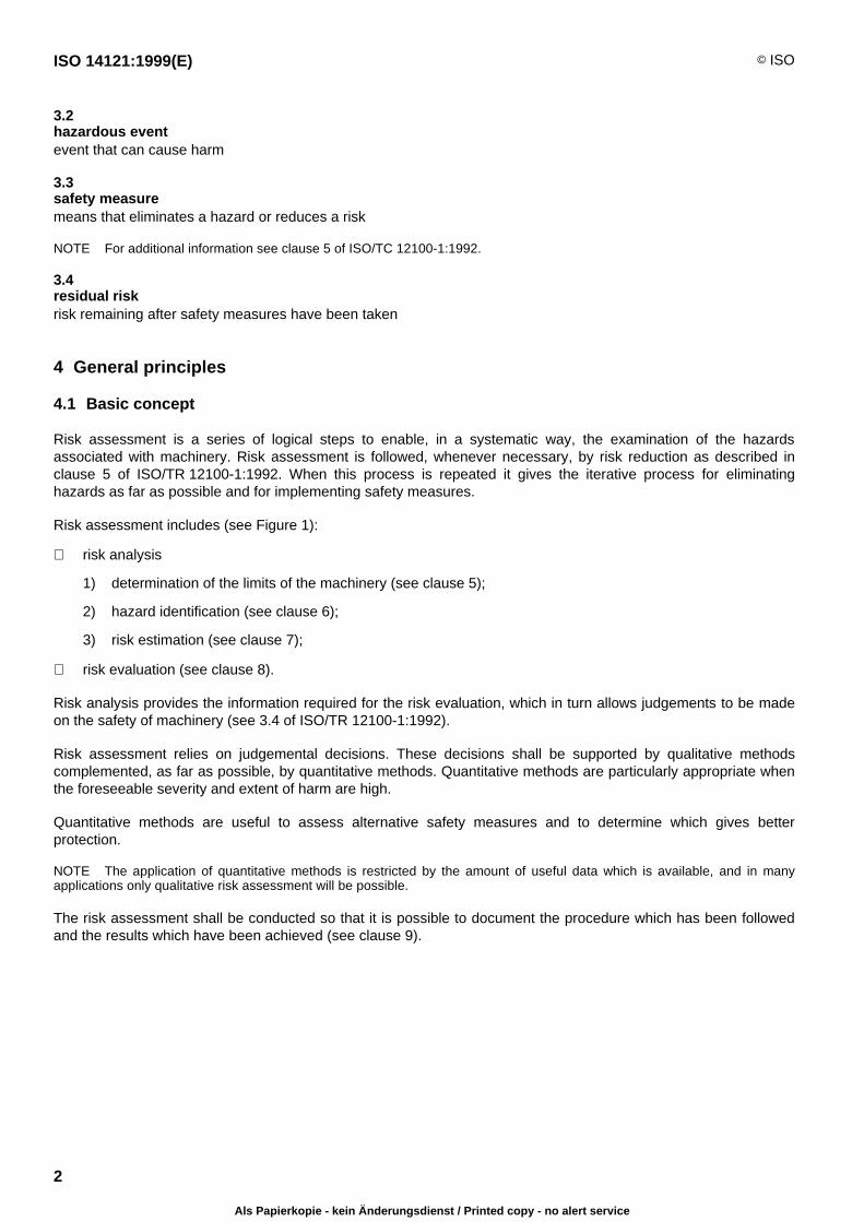
3.2hazardous eventevent that can cause harm
3.3safety measuremeans that eliminates a hazard or reduces a risk
NOTE For additional information see clause 5 of ISO/TC 12100-1:1992.
3.4residual riskrisk remaining after safety measures have been taken
4 General principles
4.1 Basic concept
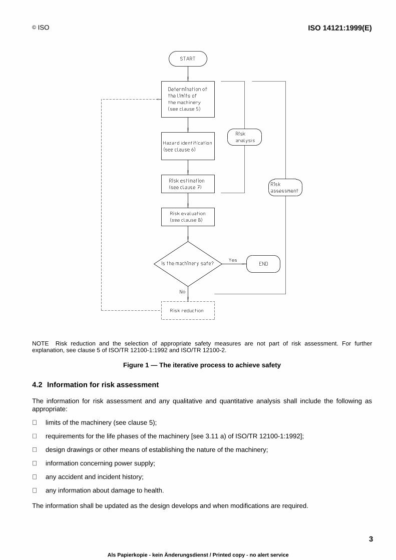
Risk assessment is a series of logical steps to enable, in a systematic way, the examination of the hazardsassociated with machinery. Risk assessment is followed, whenever necessary, by risk reduction as described inclause 5 of ISO/TR 12100-1:1992. When this process is repeated it gives the iterative process for eliminatinghazards as far as possible and for implementing safety measures.
Risk assessment includes (see Figure 1):
risk analysis
1) determination of the limits of the machinery (see clause 5);
2) hazard identification (see clause 6);
3) risk estimation (see clause 7);
risk evaluation (see clause 8).
Risk analysis provides the information required for the risk evaluation, which in turn allows judgements to be madeon the safety of machinery (see 3.4 of ISO/TR 12100-1:1992).
Risk assessment relies on judgemental decisions. These decisions shall be supported by qualitative methodscomplemented, as far as possible, by quantitative methods. Quantitative methods are particularly appropriate whenthe foreseeable severity and extent of harm are high.
Quantitative methods are useful to assess alternative safety measures and to determine which gives betterprotection.
NOTE The application of quantitative methods is restricted by the amount of useful data which is available, and in manyapplications only qualitative risk assessment will be possible.
The risk assessment shall be conducted so that it is possible to document the procedure which has been followedand the results which have been achieved (see clause 9).
Als Papierkopie - kein Änderungsdienst / Printed copy - no alert service
© ISO ISO 14121:1999(E)
3
NOTE Risk reduction and the selection of appropriate safety measures are not part of risk assessment. For furtherexplanation, see clause 5 of ISO/TR 12100-1:1992 and ISO/TR 12100-2.
Figure 1 — The iterative process to achieve safety
4.2 Information for risk assessment
The information for risk assessment and any qualitative and quantitative analysis shall include the following asappropriate:
limits of the machinery (see clause 5);
requirements for the life phases of the machinery [see 3.11 a) of ISO/TR 12100-1:1992];
design drawings or other means of establishing the nature of the machinery;
information concerning power supply;
any accident and incident history;
any information about damage to health.
The information shall be updated as the design develops and when modifications are required.
Als Papierkopie - kein Änderungsdienst / Printed copy - no alert service
ISO 14121:1999(E) © ISO
4
Comparisons between similar hazardous situations associated with different types of machinery are often possible,provided that sufficient information about hazards and accident circumstances in those situations is available.
The absence of an accident history, a small number of accidents or low severity of accidents shall not be taken asan automatic presumption of a low risk.
For quantitative analysis, data from databases, handbooks, laboratories and manufacturers' specifications may beused provided that there is confidence in the suitability of the data. Uncertaintly associated with this data shall beindicated in the documentation (see clause 9).
Data based on the consensus of expert opinion derived from experience (e.g. DELPHI Technique — see B.8) canbe used to supplement qualitative data.
5 Determination of the limits of the machinery
Risk assessment shall take into account:
the phases of machinery life (see 3.11a of ISO/TR 12100-1:1992);
the limits of machinery (see 5.1 of ISO/TR 12100-1:1992) including the intended use (both the correct use andoperation of the machinery as well as the consequences of reasonably foreseeable misuse or malfunction) inaccordance with 3.12 of ISO/TR 12100-1:1992;
the full range of foreseeable uses of the machinery (e.g. industrial, non-industrial and domestic) by personsidentified by sex, age, dominant-hand usage, or limiting physical abilities (e.g. visual or hearing impairment,size, strength);
the anticipated level of training, experience or ability of the foreseeable users such as:
1) operators (including maintenance personnel or technicians);
2) trainees and juniors;
3) general public;
exposure of other persons to the hazards associated with the machinery, where it can be reasonably foreseen.
6 Hazard identification
All hazards, hazardous situations and hazardous events associated with the machinery shall be identified. Annex Agives examples to assist in this process (see clause 4 of ISO/TR 12100-1:1992, for further information on describinghazards generated by machinery).
Several methods are available for the systematic analysis of hazards. Examples are given in annex B.
7 Risk estimation
7.1 General
After hazard identification (see clause 6), risk estimation shall be carried out for each hazard by determining theelements of risk given in 7.2. When determining these elements, it is necessary to take into account the aspectsgiven in 7.3.
Als Papierkopie - kein Änderungsdienst / Printed copy - no alert service

© ISO ISO 14121:1999(E)
5
7.2 Elements of risk
7.2.1 Combination of elements of risk
The risk associated with a particular situation or technical process is derived from a combination of the followingelements:
the severity of harm;
the probability of occurrence of that harm, which is a function of:
1) the frequency and duration of the exposure of persons to the hazard;
2) the probability of occurence of a hazardous event;
3) the technical and human possibilities to avoid or limit the harm (e.g. reduced speed, emergency stopequipment, enabling device, awareness of risks).
The elements are shown in Figure 2 and additional details are given in 7.2.2 and 7.2.3
Several methods are available for the systematic analysis of these elements. Examples are given in annex B.
NOTE In many cases these elements cannot be exactly determined, but can only be estimated. This applies especially to theprobability of occurrence of possible harm. The severity of possible harm cannot be easily established in some cases (e.g. inthe case of damage to health due to toxic substances or stress).
RISK
related tothe
consideredhazard
is a
function
of
SEVERITY
of thepossibleharm thatcan resultfrom the
consideredhazard
and PROBABILITY OF OCCURENCE of that harm
frequency and duration of exposure
probability of occurrence of hazardous event
possibility to avoid or limit the harm
Figure 2 — Elements of risk
7.2.2 Severity (degree of possible harm)
The severity can be estimated by taking into account:
— the nature of what is to be protected:
1) persons;
2) property;
3) environment;
— the severity of injuries or damage to health:
1) slight (normally reversible);
2) serious (normally irreversible);
3) death;
— the extent of harm (for each machine):
1) one person;
2) several persons.
Als Papierkopie - kein Änderungsdienst / Printed copy - no alert service
ISO 14121:1999(E) © ISO
6
7.2.3 Probability of occurrence of harm
The probability of occurrence of harm can be estimated by taking into account 7.2.3.1 to 7.2.3.3.
7.2.3.1 Frequency and duration of exposure
Need for access to the danger zone (e.g. for normal operation, maintenance or repair);
nature of access (e.g. manual feed of materials);
time spent in the danger zone;
number of persons requiring access;
frequency of access.
7.2.3.2 Probability of occurrence of a hazardous event
Reliability and other statistical data;
accident history;
history of damage to health;
risk comparison (see 8.3).
NOTE The occurrence of a hazardous event can be of technical or human origin.
7.2.3.3 Possibilities of avoiding or limiting harm
a) by whom the machinery is operated:
1) by skilled persons;
2) by unskilled persons;
3) unmanned;
b) the speed of appearance of the hazardous event:
1) suddenly;
2) fast;
3) slow;
c) any awareness of risk:
1) by general information;
2) by direct observation;
3) through warning signs and indicating devices;
d) the human possibility of avoidance or limiting harm (e.g. reflex, agility, possibility of escape):
1) possible;
2) possible under certain conditions;
3) impossible;
e) by practical experience and knowledge:
1) of the machinery;
2) of similar machinery;
3) no experience.
Als Papierkopie - kein Änderungsdienst / Printed copy - no alert service
© ISO ISO 14121:1999(E)
7
7.3 Aspects to be considered when establishing elements of risk
7.3.1 Persons exposed
Risk estimation shall take into account all persons exposed to the hazards. This includes operators (see 3.21 ofISO/TR 12100-1:1992) and other persons for whom it is reasonably foreseeable that they could be affected by themachinery.
7.3.2 Type, frequency and duration of exposure
The estimation of the exposure to the hazard under consideration (including long-term damage to health) requiresanalysis of, and shall account for, all modes of operation of the machinery and methods of working. In particular thisaffects the need for access during setting, teaching, process changeover or correction, cleaning, fault-finding andmaintenance (see 3.11 of ISO/TR 12100-1:1992).
The risk estimation shall account for situations when it is necessary to suspend safety functions (e.g. duringmaintenance).
7.3.3 Relationship between exposure and effects
The relationship between an exposure to a hazard and its effects shall be taken into account. The effects ofaccumulated exposure and synergistic effects shall also be considered. Risk estimation when considering theseeffects shall, as far as practicable, be based on appropriate recognized data.
NOTE Accident data may be available to indicate the probability and severity of injury associated with the use of a particulartype of machinery with a particular type of safety measure.
7.3.4 Human factors
Human factors can affect risk and shall be taken into account in the risk estimation. This includes, for example:
interaction of persons with the machinery;
interaction between persons;
psychological aspects;
ergonomic effects;
capacity of persons to be aware of risks in a given situation depending on their training, experience and ability.
The estimation of the ability of exposed persons shall take into account the following aspects:
application of ergonomic principles in the design of the machinery;
natural or developed ability to execute the required tasks;
awareness of risks;
level of confidence in carrying out the required tasks without intentional or unintentional deviation;
temptations to deviate from prescribed and necessary safe working practices.
Training, experience and ability can affect the risk, but none of these factors shall be used as a substitute for hazardelimination, risk reduction by design or safeguarding where these safety measures can be implemented.
7.3.5 Reliability of safety functions
Risk estimation shall take account of the reliability of components and systems. It shall:
identify the circumstances which can result in harm (e.g. component failure, power failure, electricaldisturbances);
Als Papierkopie - kein Änderungsdienst / Printed copy - no alert service
ISO 14121:1999(E) © ISO
8
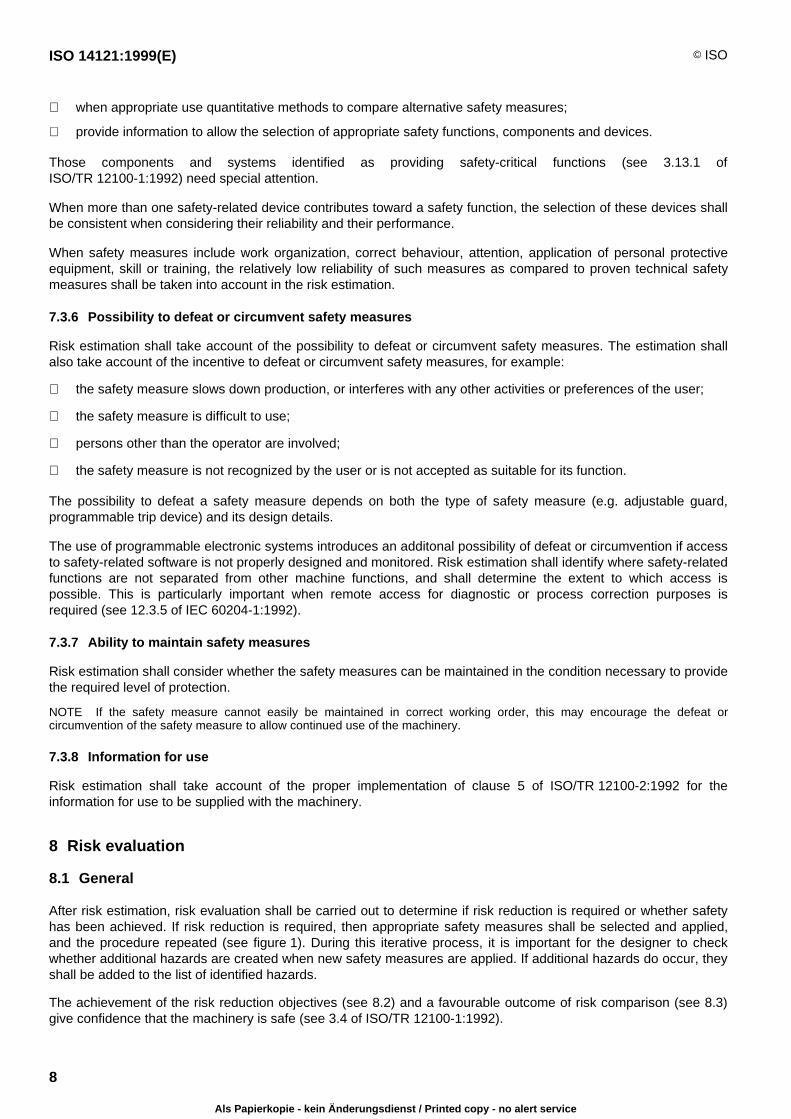
when appropriate use quantitative methods to compare alternative safety measures;
provide information to allow the selection of appropriate safety functions, components and devices.
Those components and systems identified as providing safety-critical functions (see 3.13.1 ofISO/TR 12100-1:1992) need special attention.
When more than one safety-related device contributes toward a safety function, the selection of these devices shallbe consistent when considering their reliability and their performance.
When safety measures include work organization, correct behaviour, attention, application of personal protectiveequipment, skill or training, the relatively low reliability of such measures as compared to proven technical safetymeasures shall be taken into account in the risk estimation.
7.3.6 Possibility to defeat or circumvent safety measures
Risk estimation shall take account of the possibility to defeat or circumvent safety measures. The estimation shallalso take account of the incentive to defeat or circumvent safety measures, for example:
the safety measure slows down production, or interferes with any other activities or preferences of the user;
the safety measure is difficult to use;
persons other than the operator are involved;
the safety measure is not recognized by the user or is not accepted as suitable for its function.
The possibility to defeat a safety measure depends on both the type of safety measure (e.g. adjustable guard,programmable trip device) and its design details.
The use of programmable electronic systems introduces an additonal possibility of defeat or circumvention if accessto safety-related software is not properly designed and monitored. Risk estimation shall identify where safety-relatedfunctions are not separated from other machine functions, and shall determine the extent to which access ispossible. This is particularly important when remote access for diagnostic or process correction purposes isrequired (see 12.3.5 of IEC 60204-1:1992).
7.3.7 Ability to maintain safety measures
Risk estimation shall consider whether the safety measures can be maintained in the condition necessary to providethe required level of protection.
NOTE If the safety measure cannot easily be maintained in correct working order, this may encourage the defeat orcircumvention of the safety measure to allow continued use of the machinery.
7.3.8 Information for use
Risk estimation shall take account of the proper implementation of clause 5 of ISO/TR 12100-2:1992 for theinformation for use to be supplied with the machinery.
8 Risk evaluation
8.1 General
After risk estimation, risk evaluation shall be carried out to determine if risk reduction is required or whether safetyhas been achieved. If risk reduction is required, then appropriate safety measures shall be selected and applied,and the procedure repeated (see figure 1). During this iterative process, it is important for the designer to checkwhether additional hazards are created when new safety measures are applied. If additional hazards do occur, theyshall be added to the list of identified hazards.
The achievement of the risk reduction objectives (see 8.2) and a favourable outcome of risk comparison (see 8.3)give confidence that the machinery is safe (see 3.4 of ISO/TR 12100-1:1992).
Als Papierkopie - kein Änderungsdienst / Printed copy - no alert service
© ISO ISO 14121:1999(E)
9
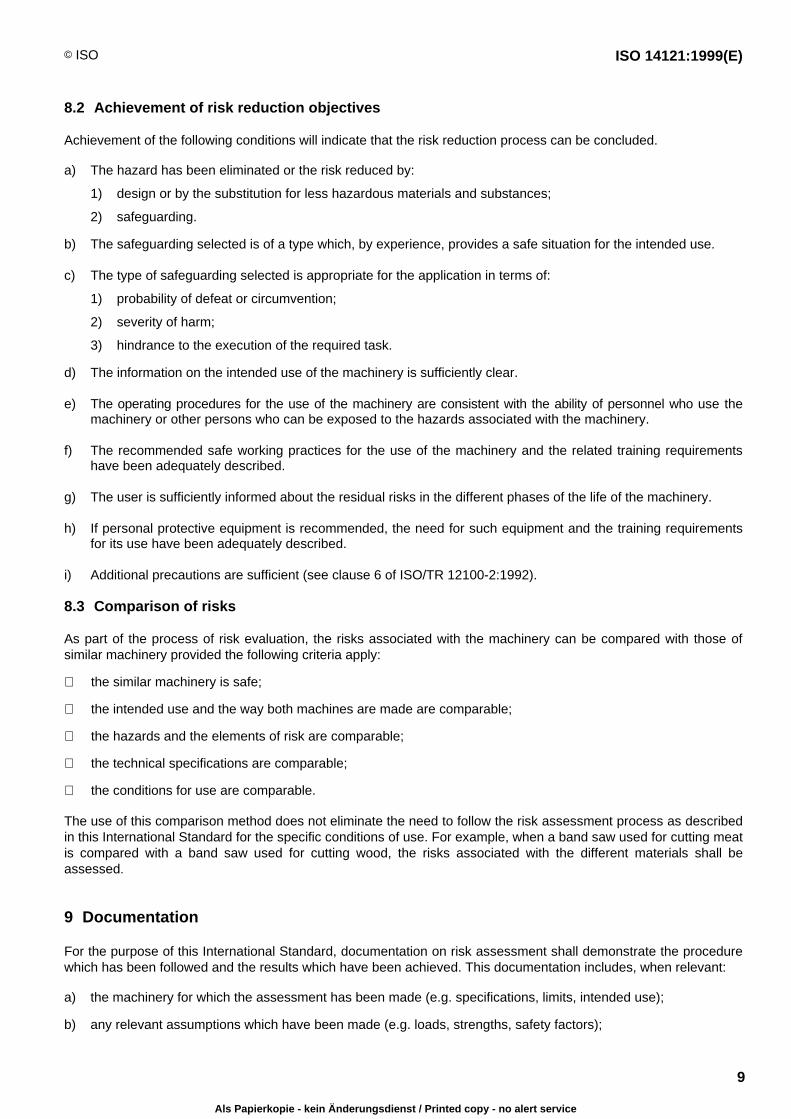
8.2 Achievement of risk reduction objectives
Achievement of the following conditions will indicate that the risk reduction process can be concluded.
a) The hazard has been eliminated or the risk reduced by:
1) design or by the substitution for less hazardous materials and substances;
2) safeguarding.
b) The safeguarding selected is of a type which, by experience, provides a safe situation for the intended use.
c) The type of safeguarding selected is appropriate for the application in terms of:
1) probability of defeat or circumvention;
2) severity of harm;
3) hindrance to the execution of the required task.
d) The information on the intended use of the machinery is sufficiently clear.
e) The operating procedures for the use of the machinery are consistent with the ability of personnel who use themachinery or other persons who can be exposed to the hazards associated with the machinery.
f) The recommended safe working practices for the use of the machinery and the related training requirementshave been adequately described.
g) The user is sufficiently informed about the residual risks in the different phases of the life of the machinery.
h) If personal protective equipment is recommended, the need for such equipment and the training requirementsfor its use have been adequately described.
i) Additional precautions are sufficient (see clause 6 of ISO/TR 12100-2:1992).
8.3 Comparison of risks
As part of the process of risk evaluation, the risks associated with the machinery can be compared with those ofsimilar machinery provided the following criteria apply:
the similar machinery is safe;
the intended use and the way both machines are made are comparable;
the hazards and the elements of risk are comparable;
the technical specifications are comparable;
the conditions for use are comparable.
The use of this comparison method does not eliminate the need to follow the risk assessment process as describedin this International Standard for the specific conditions of use. For example, when a band saw used for cutting meatis compared with a band saw used for cutting wood, the risks associated with the different materials shall beassessed.
9 Documentation
For the purpose of this International Standard, documentation on risk assessment shall demonstrate the procedurewhich has been followed and the results which have been achieved. This documentation includes, when relevant:
a) the machinery for which the assessment has been made (e.g. specifications, limits, intended use);
b) any relevant assumptions which have been made (e.g. loads, strengths, safety factors);
Als Papierkopie - kein Änderungsdienst / Printed copy - no alert service
ISO 14121:1999(E) © ISO
10
c) the hazards identified;
the hazardous situations identified;
the hazardous events considered in the assessment;
d) the information on which risk assessment was based (see 4.2);
the data used and the sources (e.g. accident histories, experiences gained from risk reduction applied tosimilar machinery);
the uncertainty associated with the data used and its impact on the risk assessment;
e) the objectives to be achieved by safety measures;
f) the safety measures implemented to eliminate identified hazards or to reduce risk (e.g. from standards or otherspecifications);
g) residual risks associated with the machinery;
h) the result of the final risk evaluation (see Figure 1).
Als Papierkopie - kein Änderungsdienst / Printed copy - no alert service

© ISO ISO 14121:1999(E)
11
Annex A(informative)
Examples of hazards, hazardous situations and hazardous events
Table A.1
Annex A of ISO/TR 12100
No. Hazards EN 292-2:1991/A1:1995 Part 1:
1992
Part 2:
1992
Hazards, hazardous situations and hazardous events
1 Mechanical hazards due to:
— machine parts or workpieces, e.g.:
a) shape;
b) relative location;
c) mass and stability (potential energy of elementswhich may move under the effect of gravity);
d) mass and velocity (kinetic energy of elements incontrolled or uncontrolled motion);
e) inadequacy of mechanical strength.
1.3 4.2 3.1, 3.2, 4
— accumulation of energy inside the machinery, e.g.:
f) elastic elements (springs);
g) liquids and gases under pressure;
h) the effect of vacuum.
1.5.3, 1.6.3 4.2 3.8, 6.2.2
1.1 Crushing hazard 1.3 4.2.1
1.2 Shearing hazard
1.3 Cutting or severing hazard
1.4 Entanglement hazard
1.5 Drawing-in or trapping hazard
1.6 Impact hazard
1.7 Stabbing or puncture hazard
1.8 Friction or abrasion hazard
1.9 High pressure fluid injection or ejection hazard 1.3.2 4.2.1 3.8
2 Electrical hazards due to:
2.1 contact of persons with live parts (direct contact) 1.5.1,1.6.3 4.3 3.9, 6.2.2
2.2 contact of persons with parts which have become liveunder faulty conditions (indirect contact)
1.5.1 4.3 3.9
2.3 approach to live parts under high voltage 1.5.1, 1.6.3 4.3 3.9, 6.2.2
2.4 electrostatic phenomena 1.5.2 4.3 3.9
2.5 thermal radiation or other phenomena such as theprojection of molten particles and chemical effects fromshort circuits, overloads, etc.
1.5.1, 1.5.5 4.3 3.9
3 Thermal hazards, resulting in:
3.1 burns, scalds and other injuries by a possible contact ofpersons with objects or materials with an extreme high orlow temperature, by flames or explosions and also by theradiation of heat sources
1.5.5,1.5.6, 1.5.7 4.4
3.2 damage to health by hot or cold working environment 1.5.5 4.4
Als Papierkopie - kein Änderungsdienst / Printed copy - no alert service

ISO 14121:1999(E) © ISO
12
Table A.1 (continued)
Annex A of ISO/TR 12100
No. Hazards EN 292-2:1991/A1:1995 Part 1:
1992
Part 2:
1992
4 Hazards generated by noise , resulting in:
4.1 hearing loss (deafness), other physiological disorders(e.g. loss of balance, loss of awareness)
1.5.8 4.5 3.2, 4
4.2 interference with speech communication, acoustic sig-nals, etc.
5 Hazards generated by vibration
5.1 Use of hand-held machines resulting in a variety ofneurological and vascular disorders
1.5.9 4.6 3.2
5.2 Whole-body vibration, particularly when combined withpoor posture
6 Hazards generated by radiation
6.1 Low-frequency, radio-frequency radiation; microwaves 1.5.10 4.7
6.2 Infrared, visible and ultraviolet radiation
6.3 X- and gamma rays
6.4 Alpha, beta rays, electron or ion beams, neutrons 1.5.10, 1.5.11 4.7 3.7.3,3.7.11
6.5 Lasers 1.5.12 4.7
7 Hazards generated by materials and substances (andtheir constituent elements) processed or used by themachinery
7.1 Hazards from contact with or inhalation of harmful fluids,gases, mists, fumes, and dusts
1.1.3, 1.5.13, 1.6.5 4.8 3.3 b), 3.4
7.2 Fire or explosion hazard 1.5.6, 1.5.7 4.8 3.4
7.3 Biological or microbiological (viral or bacterial) hazards 1.1.3, 1.6.5, 2.1 4.8
8 Hazards generated by neglecting ergonomicprinciples in machinery design, as e.g. hazards from:
8.1 unhealthy postures or excessive effort 1.1.2 d), 1.1.5, 1.6.2,1.6.4
4.9 3.6.1, 6.2.1,6.2.3, 6.2.4,6.2.6
8.2 inadequate consideration of hand-arm or foot-leganatomy
1.1.2 d), 2.2 4.9 3.6.2
8.3 neglected use of personal protection equipment 1.1.2 e) 3.6.6
8.4 inadequate local lighting 1.1.4 3.6.5
8.5 mental overload and underload, stress 1.1.2 d) 4.9 3.6.4
8.6 human error, human behavior 1.1.2 d), 1.2.2, 1.2.5,1.2.8, 1.5.4, 1.7
4.9 3.6, 3.7.8,3.7.9, 5,6.1.1
8.7 inadequate design, location or identification of manualcontrols
1.2.2 3.6.6, 3.7.8
8.8 inadequate design or location of visual display units 1.7.1 3.6.7, 5.2
Als Papierkopie - kein Änderungsdienst / Printed copy - no alert service
© ISO ISO 14121:1999(E)
13
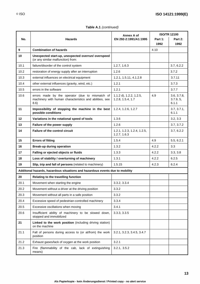
Table A.1 (continued)
Annex A of ISO/TR 12100
No. Hazards EN 292-2:1991/A1:1995 Part 1:
1992
Part 2:
1992
9 Combination of hazards 4.10
10 Unexpected start-up, unexpected overrun/ overspeed(or any similar malfunction) from:
10.1 failure/disorder of the control system 1.2.7, 1.6.3 3.7, 6.2.2
10.2 restoration of energy supply after an interruption 1.2.6 3.7.2
10.3 external influences on electrical equipment 1.2.1, 1.5.11, 4.1.2.8 3.7.11
10.4 other external influences (gravity, wind, etc.) 1.2.1 3.7.3
10.5 errors in the software 1.2.1 3.7.7
10.6 errors made by the operator (due to mismatch ofmachinery with human characteristics and abilities, see8.6)
1.1.2 d), 1.2.2, 1.2.5,1.2.8, 1.5.4, 1.7
4.9 3.6, 3.7.8,3.7.9, 5,6.1.1
11 Impossibility of stopping the machine in the bestpossible conditions
1.2.4, 1.2.6, 1.2.7 3.7, 3.7.1,6.1.1
12 Variations in the rotational speed of tools 1.3.6 3.2, 3.3
13 Failure of the power supply 1.2.6 3.7, 3.7.2
14 Failure of the control circuit 1.2.1, 1.2.3, 1.2.4, 1.2.5,1.2.7, 1.6.3
3.7, 6.2.2
15 Errors of fitting 1.5.4 4.9 5.5, 6.2.1
16 Break-up during operation 1.3.2 4.2.2 3.3
17 Falling or ejected objects or fluids 1.3.3 4.2.2 3.3, 3.8
18 Loss of stability / overturning of machinery 1.3.1 4.2.2 6.2.5
19 Slip, trip and fall of persons (related to machinery) 1.5.15 4.2.3 6.2.4
Additonal hazards, hazardous situations and hazardous events due to mobility
20 Relating to the travelling function
20.1 Movement when starting the engine 3.3.2, 3.3.4
20.2 Movement without a driver at the driving position 3.3.2
20.3 Movement without all parts in a safe position 3.3.2
20.4 Excessive speed of pedestrian-controlled machinery 3.3.4
20.5 Excessive oscillations when moving 3.4.1
20.6 Insufficient ability of machinery to be slowed down,stopped and immobilized
3.3.3, 3.3.5
21 Linked to the work position (including driving station)on the machine
21.1 Fall of persons during access to (or at/from) the workposition
3.2.1, 3.2.3, 3.4.5, 3.4.7
21.2 Exhaust gases/lack of oxygen at the work position 3.2.1
21.3 Fire (flammability of the cab, lack of extinguishingmeans)
3.2.1, 3.5.2
Als Papierkopie - kein Änderungsdienst / Printed copy - no alert service
ISO 14121:1999(E) © ISO
14
Table A.1 (continued)
Annex A of ISO/TR 12100
No. Hazards EN 292-2:1991/A1:1995 Part 1:
1992
Part 2:
1992
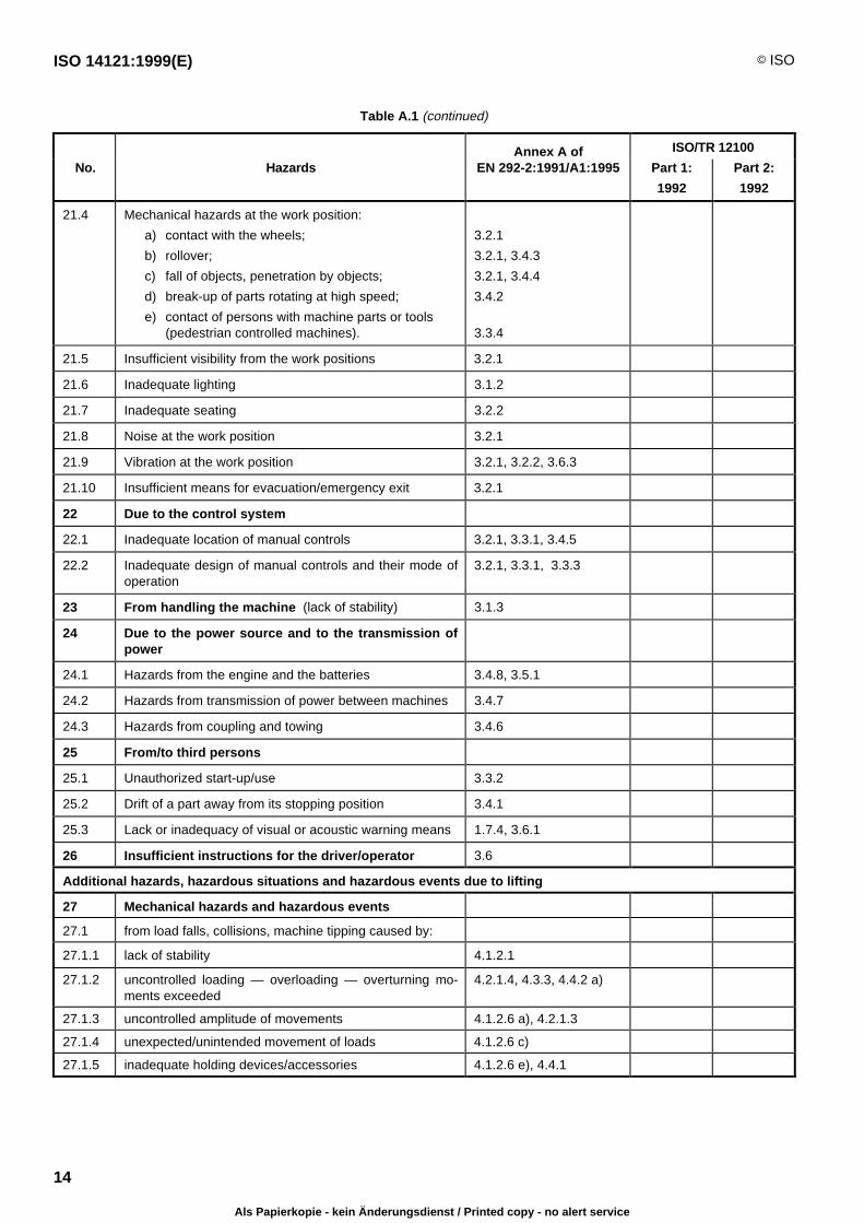
21.4 Mechanical hazards at the work position:
a) contact with the wheels;
b) rollover;
c) fall of objects, penetration by objects;
d) break-up of parts rotating at high speed;
e) contact of persons with machine parts or tools(pedestrian controlled machines).
3.2.1
3.2.1, 3.4.3
3.2.1, 3.4.4
3.4.2
3.3.4
21.5 Insufficient visibility from the work positions 3.2.1
21.6 Inadequate lighting 3.1.2
21.7 Inadequate seating 3.2.2
21.8 Noise at the work position 3.2.1
21.9 Vibration at the work position 3.2.1, 3.2.2, 3.6.3
21.10 Insufficient means for evacuation/emergency exit 3.2.1
22 Due to the control system
22.1 Inadequate location of manual controls 3.2.1, 3.3.1, 3.4.5
22.2 Inadequate design of manual controls and their mode ofoperation
3.2.1, 3.3.1, 3.3.3
23 From handling the machine (lack of stability) 3.1.3
24 Due to the power source and to the transmission ofpower
24.1 Hazards from the engine and the batteries 3.4.8, 3.5.1
24.2 Hazards from transmission of power between machines 3.4.7
24.3 Hazards from coupling and towing 3.4.6
25 From/to third persons
25.1 Unauthorized start-up/use 3.3.2
25.2 Drift of a part away from its stopping position 3.4.1
25.3 Lack or inadequacy of visual or acoustic warning means 1.7.4, 3.6.1
26 Insufficient instructions for the driver/operator 3.6
Additional hazards, hazardous situations and hazardous events due to lifting
27 Mechanical hazards and hazardous events
27.1 from load falls, collisions, machine tipping caused by:
27.1.1 lack of stability 4.1.2.1
27.1.2 uncontrolled loading — overloading — overturning mo-ments exceeded
4.2.1.4, 4.3.3, 4.4.2 a)
27.1.3 uncontrolled amplitude of movements 4.1.2.6 a), 4.2.1.3
27.1.4 unexpected/unintended movement of loads 4.1.2.6 c)
27.1.5 inadequate holding devices/accessories 4.1.2.6 e), 4.4.1
Als Papierkopie - kein Änderungsdienst / Printed copy - no alert service

© ISO ISO 14121:1999(E)
15
Table A.1 (concluded)
Annex A of ISO/TR 12100
No. Hazards EN 292-2:1991/A1:1995 Part 1:
1992
Part 2:
1992
27.1.6 collision of more than one machine 4.1.2.6 b)
27.2 from access of persons to load support 4.3.3
27.3 from derailment 4.1.2.2
27.4 from insufficient mechanical strength of parts 4.1.2.3
27.5 from inadequate design of pulleys, drums 4.1.2.4
27.6 from inadequate selection of chains, ropes, lifting andaccessories and their inadequate integration into themachine
4.1.2.4, 4.1.2.5, 4.3.1,4.3.2
27.7 from lowering of the load under the control of frictionbrake
4.1.2.6 d)
27.8 from abnormal conditions ofassembly/testing/use/maintenance
4.4.1, 4.4.2 d)
27.9 from the effect of load on persons (impact by load orcounterweight)
4.1.2.6 b), 4.1.2.7, 4.2.3
28 Electrical hazards
28.1 from lightning 4.1.2.8
29 Hazards generated by neglecting ergonomicprinciples
29.1 insufficient visiblity from the driving position 4.1.2.7, 4.4.2 c)
Additional hazards, hazardous situations and hazardous events due to underground work
30 Mechanical hazards and hazardous events due to:
30.1 lack of stability of powered roof supports 5.1
30.2 failure of accelerator or brake control of machinery run-ning on rails
5.4
30.3 failure or lack of deadman's control of machinery runningon rails
5.4, 5.5
31 Restricted movement of persons 5.2
32 Fire and explosion 5.6
33 Emission of dust, gases etc. 5.7
Additional hazards, hazardous situations and hazardous events due to the lifting or moving of persons
34 Mechanical hazards and hazardous events due to:
34.1 inadequate mechanical strength; inadequate workingcoefficients
6.1.2
34.2 failure of loading control 6.1.3
34.3 failure of controls in personnel carrier (function, priority) 6.2.1
34.4 overspeed of personnel carrier 6.2.3
35 Falling of person from personnel carrier 1.5.15, 6.3.1, 6.3.2, 6.3.3,
36 Falling or overturning of personnel carrier 6.4.1, 6.4.2
37 Human error, human behaviour 6.5
Als Papierkopie - kein Änderungsdienst / Printed copy - no alert service
ISO 14121:1999(E) © ISO
16
Annex B(informative)
Methods for analysing hazards and estimating risk
B.1 General
There are many methods of hazard analysis and risk estimation and only a few are given in this annex. Alsoincluded are risk analysis techniques which combine hazard analysis with risk estimation.
Each method has been developed for particular applications. Therefore it may be necessary to modify some detailsfor the special application for machinery.
There are two basic types of risk analysis: one is called the deductive method and the other the inductive method. Inthe deductive method, the final event is assumed and the events which could cause this final event are then sought.In the inductive method, the failure of a component is assumed. The subsequent analysis identifies the eventswhich this failure could cause.
B.2 Preliminary Hazard Analysis (PHA)
PHA is an inductive method whose objective is to identify, for all phases of life of a specified system/subsystem/component, the hazards, hazardous situations and hazardous events which could lead to an accident. The methodidentifies the accident possibilities and qualitatively evaluates the degree of possible injury or damage to health.Proposals for safety measures and the result of their application are then given.
PHA should be updated during the phases of design, building and testing, to detect new hazards and to makecorrections, if necessary.
The description of the obtained results can be presented in different ways (e.g. table, tree).
B.3 “What-if” method
The “what-if” method is an inductive method. For relatively simple applications, the design, operation and use of amachine is reviewed. At each step, “what-if” questions are formulated and answered to evaluate the effects ofcomponent failures or procedural errors on the creation of hazards at the machine.
For more complex applications, the “what-if” method can be best applied through the use of a checklist and bydividing the work, in order to assign certain aspects of the use of the machine to the persons having the greatestexperience or skill in evaluating those aspects. Operator practices and job knowledge are audited. The suitability ofequipment, the design of the machine, its control system and its safety equipment are assessed. The effects of thematerial being processed are reviewed, and the operating and maintenance records are audited. Generally, achecklist evaluation of the machine precedes use of the more sophisticated methods described below.
B.4 Failure Mode and Effects Analysis (FMEA)
FMEA is an inductive method in which the main purpose is to evaluate the frequency and consequences ofcomponent failure. When operating procedures or operator error are significant, other methods can be moresuitable.
FMEA can be more time-consuming than a fault tree, because for every component every mode of failure isconsidered. Some failures have a very low probability of occurrence. If these failures are not analysed in depth, thisdecision preferably should be recorded in the documentation.
The method is specified in IEC 60812.
Als Papierkopie - kein Änderungsdienst / Printed copy - no alert service
© ISO ISO 14121:1999(E)
17
B.5 Fault simulation for control systems
In this inductive method, the test procedures are based on two criteria: technology and complexity of the controlsystem. Principally, the following methods are applicable:
practical tests on the actual circuit and fault simulation on actual components, particularly in areas of doubt,regarding performance identified during the theoretical check and analysis;
a simulation of control behaviour (e.g. by means of hardware and/or software models).
Whenever complex safety-related parts of control systems are tested, it is usually necessary to divide the systeminto several functional subsystems and to exclusively submit the interface to fault simulation tests.
This technique can also be applied to other parts of machinery.
B.6 MOSAR method (Method Organized for a Systemic Analysis of Risks)
MOSAR is a complete approach in ten steps. The system to be analysed (machinery, process, installation, etc.) isconsidered as number of subsystems which interact. A table is used to identify the hazards, the hazardoussituations and the hazardous events.
The adequacy of the safety measures is studied with a second table, with a third table taking into account theirinterdependency.
A study, using known tools (such as FMEA) underlines the possible dangerous failures. This leads to theelaboration of accident scenarios. By consensus, the scenarios are sorted in a severity table.
A further table, again by consensus, links the severity with the objectives to be met by the safety measures andspecifies the performance levels of technical and organizational measures.
The safety measures are then incorporated into logic trees and the residual risks are analysed via an acceptabilitytable defined by consensus.
B.7 Fault Tree Analysis (FTA)
FTA is a deductive method carried out from an event considered as unwanted, and enables the user of this methodto find the whole set of critical paths that lead to the unwanted event.
Hazardous or top events are first identified. Then all combinations of individual failures that can lead to thathazardous event are shown in the logical format of the fault tree. By estimating the individual failure probabilities,and then using the appropriate arithmetical expressions, the top-event probability can be calculated. The impact of asystem change on the top-event probability can readily be evaluated, and thus FTA makes it easy to investigate theimpact of alternative safety measures. It has also been found useful in determining the cause of accidents.
The method is specified in IEC 61025.
B.8 DELPHI Technique
A large circle of experts is questioned in several steps, whereby the result of the previous step together withadditional information is communicated to all participants.
During the third or fourth step, the anonymous questioning concentrates on those aspects for which no agreementis reached so far.
Basically, Delphi is a forecasting method which is also used in generating ideas. This method is particularly efficientdue to its limitation to experts.
Als Papierkopie - kein Änderungsdienst / Printed copy - no alert service
ISO 14121:1999(E) © ISO
18
Bibliography
C.1 International Standards in which methods for analysing hazards and estimatingrisks are specified
[1] ISO/IEC Guide 51:1990, Guidelines for the inclusion of safety aspects in standards.
[2] IEC 60812:1985, Analysis techniques for system reliability — Procedure for failure mode and effects analysis(FMEA).
[3] IEC 61025:1990, Fault tree analysis (FTA).
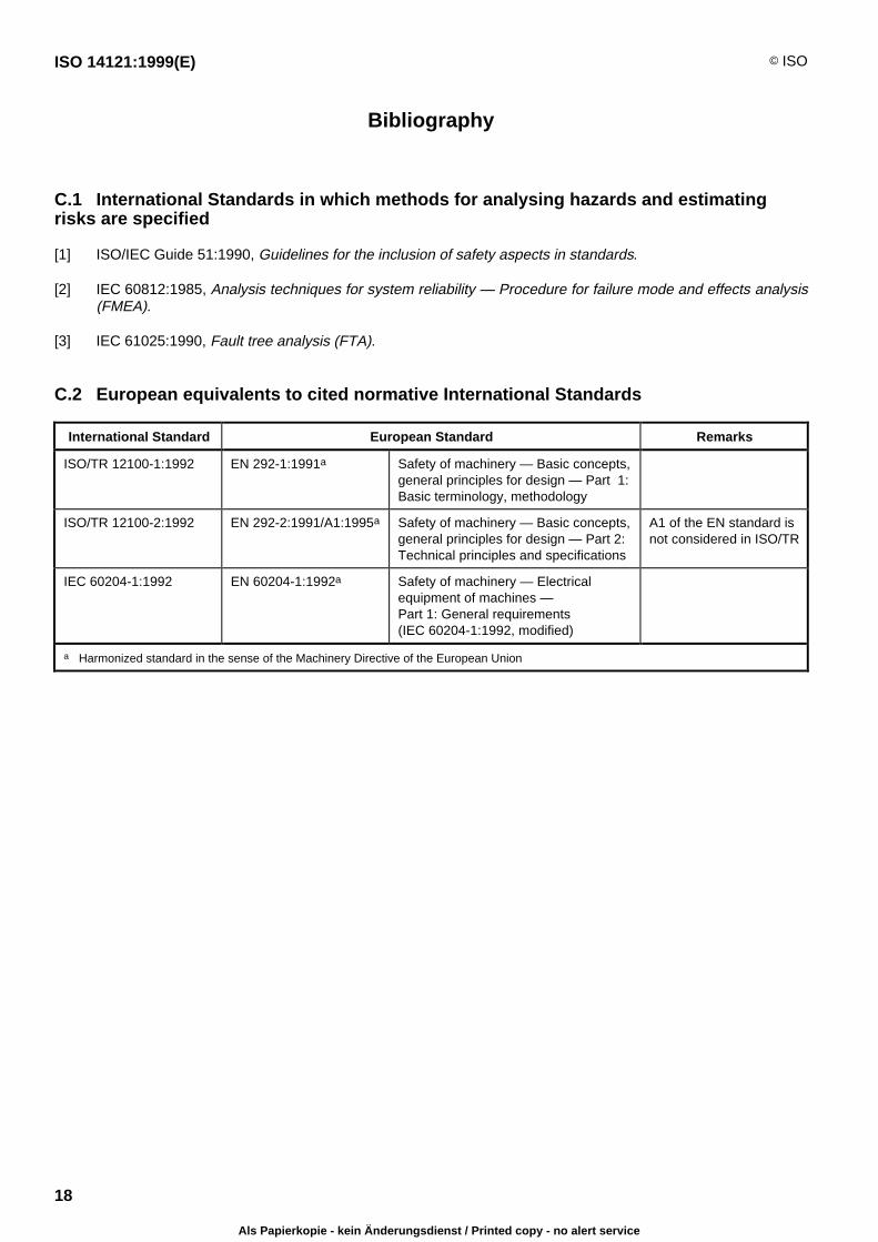
C.2 European equivalents to cited normative International Standards
International Standard European Standard Remarks
ISO/TR 12100-1:1992 EN 292-1:1991a Safety of machinery — Basic concepts,general principles for design — Part 1:Basic terminology, methodology
ISO/TR 12100-2:1992 EN 292-2:1991/A1:1995a Safety of machinery — Basic concepts,general principles for design — Part 2:Technical principles and specifications
A1 of the EN standard isnot considered in ISO/TR
IEC 60204-1:1992 EN 60204-1:1992a Safety of machinery — Electricalequipment of machines —Part 1: General requirements(IEC 60204-1:1992, modified)
a Harmonized standard in the sense of the Machinery Directive of the European Union
Als Papierkopie - kein Änderungsdienst / Printed copy - no alert service

Als Papierkopie - kein Änderungsdienst / Printed copy - no alert service

ISO 14121:1999(E) © ISO
ICS 13.110
Descriptors: safety of machines, accident prevention, safety measures, hazards, risk analysis, risk management, generalities.
Price based on 18 pages
Als Papierkopie - kein Änderungsdienst / Printed copy - no alert service