Embed Size (px)
Citation preview

ISO 26262 - Tool Chain Analysis
Reduces Tool Qualification Costs
Oscar Slotosch,
Martin Wildmoser,
Jan Philipps,
Reinhard Jeschull
Validas AG
München
<surname>@validas.de
Rafael Zalman
Infineon Technologies AG
Neubiberg
Abstract: Software tools in safety related projects are indispensable, but also in-
troduce risks. A tool error may lead to the injection or non-detection of a fault in
the product. For this reason the safety norm for road vehicles, ISO 26262, requires
determination of a tool confidence level for each software tool. In this paper we
present a model-based approach to represent a tool chain, its potential errors and
the counter-measures for these. In this model tools are not only error sources, but
can also act as error sinks for other tools by providing appropriate checks and re-
strictions. The tool work flow in a project can be rearranged or extended to make
the integrated tool chain safer than its parts and to reduce tool qualification costs
greatly. The tool chain model not only identifies the critical tools, but also exposes
very specific qualification requirements for these. The paper illustrates and aug-
ments this approach with experiences and results from an application to a real in-
dustrial automotive tool chain consisting of 37 tools.
1 Introduction
The increasing visibility of development and safety standards such as the ISO 26262 is a
sign of the growing maturity of the field of embedded software development. Growing
maturity of an engineering field is quite naturally accompanied with a stronger emphasis
on choice and suitability of tools. While some earlier standards demanded a kind of
statement of “fitness for use”, which was often provided through certification, the ISO
26262 takes a more holistic view and demands that tools are evaluated, and if necessary
also qualified, in the context of their use in the development tool chain.
Thus, tool qualification in ISO 26262 [ISO26] is a two-step process. In the first step,
tools are evaluated (see Fig 1) to determine a tool confidence level (TCL), based on the
tool impact (TI) and on the tool error detection level (TD).

Fig 1. Tool evaluation according to ISO 26262:2011-8
The TI denotes the possibility of tool errors leading to a violation of a safety requirement
and the TD expresses the likelihood of detecting or preventing tool errors.
In the second step, depending on the TCL and the safety integrity level of the develop-
ment object, further qualification measures are demanded, such as for instance extensive
and focussed tests (tool validation).
The safety norm ISO 26262 offers the possibility to avoid tool qualification by enriching
the development process with additional checks and restrictions in order to detect or pre-
vent all potential tool errors with high probability. With the additional checks and re-
strictions, the tool confidence level can sometimes be lowered to TCL1, where no tool
qualification is needed.
In contrast to concrete tool errors, e.g. a bug in function X of tool Y, a potential tool er-
ror is a fictive and abstract error of a tool, e.g. loss of data in an output artifact, and de-
notes something that can go wrong in a tool of a certain type according to Murphy’s law.
Please also note that we use the term tool error to identify the occurrence of wrong tool
behavior in a use case and not its cause, that is a fault or defect in the tool’s code. In an-
other paper [WPS12] we further distinguish between tool errors, which are internal to
tool, and tool failures, which are external to tool and occur at the output side, according
to Laprie’s fault/error/failure model [L92], but in this paper we rather only use the term
tool error for both in order to be more consistent with the ISO 26262 terminology.
Tool errors can be mitigated by counter measures in the form of checks or restrictions. A
check is a counter measure that detects tool errors after they have occurred, e.g. by in-
specting the tool’s output artifacts. A restriction is a counter measure that prevents tool
errors from occurring, e.g. by limiting the input space or used functions of a tool. Note
that we usually cannot detect or prevent the cause of tool errors – i.e., tool faults –, as
this would require measures on the tool’s code or in its development process.
While there is a certain body of work on tool validation issues [SC04, SS07] and some
work on specific tool use patterns to reduce the need of tool validation [Be10], there is
so far little work that considers the holistic approach of establishing tool confidence ac-
cording to ISO 26262. A notable exception is [Hi11], where the process of tool evalua-
tion is explained in detail and some practical extensions are proposed.
Recently, an increasing emphasis on tool qualification can also be noticed in other safety
norms besides the ISO 26262. The second edition of IEC 61508 [61508], the general
safety norm for E/E/P systems, demands all software offline-support tools to be classi-
fied in levels T1-T3, but this is done for each tool in isolation and there is no way to

avoid qualification of T3 tools. Another example is DO-178C [DO178], the safety norm
for the avionic domain, which also has a twofold strategy of first classifying tools in lev-
els TQL1 to TQL5 and then qualifying them by designated activities described in DO-
330 [DO330].
The classification in DO-178C is also based on the possibility of a tool to insert or fail to
detect product errors, but is not dependent on the possibility of detecting or avoiding
these tool errors elsewhere within the development process.
2 Tool Evaluation Process
Tool evaluation is about determining the TCL for all tools used in the development pro-
cess. Our model-based tool evaluation process consists of the following steps:
(a) Model the tool chain with
• tools,
• use cases and
• artifacts.
(b) Determine tool impact for every use case
(c) Identify potential tool errors for every use case
(d) Identify and assign measures for error detection and –prevention
(e) Validate the model
• Automated Plausibility Checks
• Generation of tables for reviewing the tool chain model
• Rework the model according to the review results
(f) Generate a report including the computed tool confidence level for each tool
Step (a) results in a model of the tool chain to be analyzed. Before we discuss this model
in detail let us look at an example. Assume a tool chain (see Fig 2) for testing product
source code, e.g. software modules, with the aim of achieving 100% requirements cover-
age and 100% MC/DC structural coverage.
Our testing tool chain consists of three tools: a test automation tool (TAU), a compiler
and an execution platform. The TAU is employed for the use case “RunTest”, which
involves coverage instrumentation, test application generation and the call of other tools,
that is compiler and platform, in order to execute a test case. The use case “RunTest”
takes the product source files and a test case definition file (stimuli+references) as input
and delivers as output an instrumented version of the product source files and the test
application source code, which is the extra code needed for calling the functions to be
tested with the inputs specified in the test case definition and to collect and compare the
resulting values with the reference values from the test case definition.

The TAU calls the use cases “CompileApp” and “LinkApp” of the tool “Compiler” in
order to produce the test application binary “TestApp ELF” and the use case “RunApp”
of the tool “Platform” to execute the test application binary, e.g. by flashing it to an
evaluation board, starting up the application and sending back the results via a commu-
nication software, e.g. terminal for COM messages.
The test output consists of verdicts of the form PASS or FAIL denoting the result of
comparing the actual output values with the corresponding references and the coverage
hits denoting the exercised parts of the product source code. The TAU receives these test
results from the tool “Platform” and uses them to produce a summary test report.
Fig 2. Example: Testing tool chain, contains some errors without counter measures
After the tool chain is modeled the next step (b) is to determine the tool impact for each
use case. According to ISO 26262 a tool or use case has TI1 if there is no possibility that
a potential tool error can lead to the injection or non-detection of a fault in the safety-
related product, i.e. a violation of a safety requirement. Otherwise, if there is such a pos-
sibility or if the question cannot be answered the result is TI2.
In step (b) it is not only important to write down the decision (TI1, TI2), but also the
reasons for this decisions. For example if a tool has no data flow to the safety related
parts of the product and is not used for a verification step, then one can argue that such a
tool is TI1.
For every use case having TI2 the next step (c) is to determine potential tool errors and
then in step (d) to find possible counter measures for these if these exist.
In the testing tool chain we can identify several potential tool errors for the use cases,
that might lead to the injection or non-detection of product faults. On the other hand
there are also several possibilities to detect or avoid these potential errors within these
use cases.
For example, the compiler may have a defect with leads to the injection of a fault into
the product object file. However, this potential error “Wrong Product OBJ Code Behav-
iour” of use case “CompileApp” can very likely be detected by the check “Compare
Outputs with Reference Values”, which is part of the use case “RunTest” of the tool
TAU.

However, if a compiler defect hits the test application code, e.g. “Wrong TestApp OBJ
Code Behaviour” in use case “CompileApp”, the test execution itself might get com-
promised and a product fault, either injected by a tool defect or manually inserted by the
developer, might slip through. Also, if the TAU reports wrong coverage, i.e. potential
error “Wrong Coverage Reported” of use case “RunTest”, it might not be noticed by the
tester that parts of the product code have not been covered by tests and product faults
residing in these unexercised parts might slip through.
After the tool chain model is adjusted with potential errors and counter measures the
next step (d) is to validate this model, that is to check if it resembles correctly and com-
pletely the tool chain as it used in the development process and if the modeled errors and
counter measures are feasible. In the end of the next section we will show how this step
can be assisted with automatic plausibility checks and review tables generated from the
model.
Once the model is validated the final step (e) is the computation of the TCL for each use
case and tool and the generation of a report that contains the resulting TCLs and the way
these are derived.
3 Meta Model for Tool Chains
To define and analyze tool chains we propose a simple domain specific tool chain model
(see Fig 3), which consists of the following elements: Tool Chain, Tool, Use Case, Arti-
fact, Error, Check, Restriction and Qualification.
The model shall represent two aspects:
• the tool chain structure consisting of tools, use cases and artifacts
• the tool confidence by representing the potential errors and assigned checks or
restrictions
In the model a tool chain consists of tools, use cases and artifacts. Each tool has its dis-
tinct use cases, which describe the purpose for the tool within the project. Each use case
has its own sets of artifacts, which are read, written or modified by the use case and can
be assigned a TI (TI1, TI2).

Fig 3. Domain Model for Tool Chains
To model the tool confidence situation each use case is associated with a set of potential
errors, which may be assigned to checks or restrictions provided by the same or other use
cases possibly from other tools. In our example tool chain (see Fig 2) the potential error
“Flash Corruption” is assigned to the check “Memory Checksum Check” provided by
the same use case “RunApp” from the tool “Platform”, i.e. a simulator or a board with
corresponding connection software.
Each check and restriction has its own effectiveness expressed by the TD level (TD1-
TD3).
By using TI and TD for all identified potential errors, the TCL for a use case or a tool
can be computed automatically according to the ISO 26262 table (see Fig 1) by propa-
gating the maximum TD or TCL upwards.
Qualifications (including a selectable qualification method) can be added to tool chains,
tools and use cases to model available qualifications and to check their compliance with
respect to a given ASIL in a tool chain.
A more detailed description of the classes, attributes and relations can be found in the
user manual of the Tool Chain Analyzer tool [TCA] that has been developed by Validas
to support the tool chain modeling (see Fig 4) described here.
Building a formal model requires some effort, but it brings the following benefits:
• Models can be adapted easily, e.g. updating names in a consistent manner
• Models can be automatically checked for inconsistencies via plausibility
checks:
o Emptiness checks: Unchecked errors, use cases without errors, unused
artifacts

o Error assignment checks: Without dataflow from use case A to use
case B via an artifact, the use case B cannot detect errors of A and A
cannot prevent errors in B. This restricts the set of selectable
checks/restrictions that can be assigned to an error.
o Checks for sufficient descriptions: Missing descriptions of elements or
missing explanations for high mitigation probabilities or the postula-
tion that a tool has no impact.
o Checks for existence of adequate qualifications: If in a model all ele-
ments with a TCL > 1 have qualifications with appropriate methods
(as specified in the ISO 26262 tables) for the selected ASIL, then the
tool chain is ISO 26262 compliant.
• Models for tools can be easily exchanged and reused, even if the checks and re-
strictions are distributed on other tools, for example a code generator model
which requires some checks of a test tool can be exported including only the re-
quired checks.
• Review of tool chain models is supported by having automatically generated
review checklists for tool chains (tool/use case-artifact matrix) and the tool con-
fidence model (list of errors and their assigned counter-measures with TD).
• Rework and Change-tracking is assisted. The modeler can express the reasons
for his/her decisions as comments and mark elements as assumption in order to
make clear that these elements express proposals (to be accepted) and not facts
(existing checks, restrictions) in the current development process. The modeler
can also deactivate elements with the option to restore them later, which allows
to analyze the effect of removing a tool to the TCLs of the remaining tools.
• Automatic generation of reports for model description (text+figures) and the
derivation of the TCL for each use case and tool. The report is structured ac-
cording to the ISO 26262 requirements for the work product tool criteria evalu-
ation report.
Fig 4. Tool Chain Analyzer with generated figures and tables (MS Word)

4 Tool Chain Extensions and Rearrangements
An important part of evaluating a tool chain is to find and assign checks or restrictions
for the identified potential errors. There are various ways to rearrange or extend an exist-
ing tool chain (see Fig 5), such that it becomes more resilient to tool errors. Often intro-
ducing additional checks before or after a use case helps to detect or prevent errors. For
example the error “Wrong Options Used” by the use case Compile-App from the exam-
ple above can be detected by having a “Logfile Inspection” check in the use case. With
“Logfile Inspection” we mean redirecting every compiler call to a log file and then ask-
ing the user to inspect this log file for correct compiler calls.
A very general counter measure is to introduce redundant and independently developed
tools for the same purpose. For example many errors from the tool chain above can be
detected by having a validation test run, where an alternative coverage tool and compiler
is used, at least once before the product is released. In this context special care is re-
quired to avoid common cause failures. As an example, common cause failures may oc-
cur because of common components, e.g. commercial parser frontends for embedded
compilers.
Also note that there are circumstances, where it suffices to have structural coverage
measured in other tests on the same code. For example if 100% MC/DC is a test aim of
two different test levels and different coverage tools are used at both levels one can ar-
gue that there is a high chance that missed paths in the product code that are not detected
in one test bench due to “Wrong Coverage Reported” will be detected in the other with
high probability provided the acceptance criteria are equally strong. However, an argu-
mentation like this needs to be worked out carefully and requires checking side-
conditions: For instance, are the same test design methods used, and are and equivalent
test goals, e.g. full functional requirement coverage, applied in both test levels?

Fig 5. Extended testing tool chain, all errors have counter measures
5 Industrial Experience
We have applied the model based approach to a real industrial tool chain consisting of
37 tools, which is used for automotive SW development of hardware near SW modules.
In total we have identified 136 distinct use cases in this tool chain over the whole devel-
opment lifecycle, e.g. Requirements, Design, Coding, Unit Tests, Integration Tests, Sys-
tem Tests and Maintenance.

Fig 6. TCL status of the industrial tool chain during evaluation
The tool chain evaluation was carried out iteratively having the following phases Alpha,
Beta, RC, Release. In each phase some adjustments have been made, e.g. dropping un-
feasible checks or restrictions or considering some of these as they are implemented in
the development process. As a consequence the TCL of tools varied from stage to stage
as shown in the table above (see Fig 6).
The aim of the Alpha model was to get the tool chain structure complete and correct that
is to have all tools, artifacts and use cases captured.
In the Beta model the tool chain analysis added potential errors and possible counter
measures for these. In a detailed review of this Beta model the tool experts, that is the
developers that use these tools in the development project, rejected, confirmed or added
errors, checks or restrictions in the Beta model.
The RC model contained all potential errors and only checks and restrictions that are
already implemented in the development process. The RC model thus reflects the tool
confidence situation of the initial development process. In this initial process 11 tools
have TCL2 or TCL3 and would thus require qualification.
In the Release model some extra checks and restrictions, which have been identified and
accepted during evaluation have been added to the process. Most of these extra counter-
measures were “quick wins”, that is measures that do not require much extra effort, e.g.
Logfile Inspection.
By implementing this reworked tool chain the TCL for 10 tools could be brought to
TCL1, only one tool remained at TCL2. Hence, the effort spent in analyzing and rework-
ing the tool chain paid off by saving the need for qualifying 10 tools. In addition the
model made clear what functions of the remaining TCL2 tool need to be qualified and a
suitable qualification kit can be constructed or demanded from the tool vendor.
The effort for the model-based tool chain evaluation varied between 0,5 and 5 days (2
days average) per tool. The effort increases with the number of use cases and interac-
tions to other tools. A monolithic tool, e.g. Zip, is typically simple whereas distributed
tools are typically complex, e.g. a test tool with lots of interactions to other tools (com-
piler, coverage tool, repository) and distributed processes (test application running on
eval board, test management running on PC). Using a suggested default tool evaluation
or classification from the literature

[LPP10], with which we were able to derive the TCL for 25 of the 37 tools within one
hour, resulted in qualification needs for 12 tools. If we compare this with the result of only one tool to be qualified as achieved in our mo-
del and process based evaluation we get a big difference in terms of costs: assuming only 10
1 days of work for qualification per tool (or comparable
amounts of money) this would cause 120 days of qualification work, which is the double amount of effort than classifying 25 tools with 2 days each and qualifying only one tool (25*2+10=60). Furthermore 12 tools cannot be classified using this default classification
[LPP10] as they do not fall into one of the mentioned categories.
6 Conclusion
In this paper we have proposed a meta model for tool chains and a method for using this
modeling for tool chain evaluation, that is TCL determination, according to ISO 26262.
Having a model-based tool chain evaluation brings the following benefits:
• Automation (TCL computation, Report Generation)
• Adaptivity (Incremental Changes)
• Explorability (What effect do changes have?)
• Rework support (Review checklists, Change tracking)
• Enhanced quality assurance due to automated plausibility checks
The safety norm ISO 26262 offers a lot of flexibility to reach confidence in the use of
tools. It considers tools together with the process they are used in and thus offers the
possibility to adapt a process such that potential tool errors are detected with high proba-
bility within this process. This is a great opportunity to reduce the costs for tool qualifi-
cation.
On the other hand the use of qualified tools can reduce the process overhead and opti-
mize the development and test processes by eliminating some checks and restrictions
needed for working with unqualified tools (even if they can be partially automated).
Note that sometimes qualification kits that can be purchased bring along additional
checks and restrictions, e.g. input range restrictions, to ensure the correct use of the tool
in the perimeter of the use cases and functions covered by the qualification kit. Finding
the optimal balance between development cost and qualification costs depends on the
number and size of use cases of the tool and differs in each application scenario or com-
pany.The author area is a Word table. To insert or remove authors, insert or remove col-
umns through Word’s Table menu. Use this menu also to adjust table and column width.
1 If qualification kits are not available it may be much more work to qualify a tool by building an adequate
qualification kit.
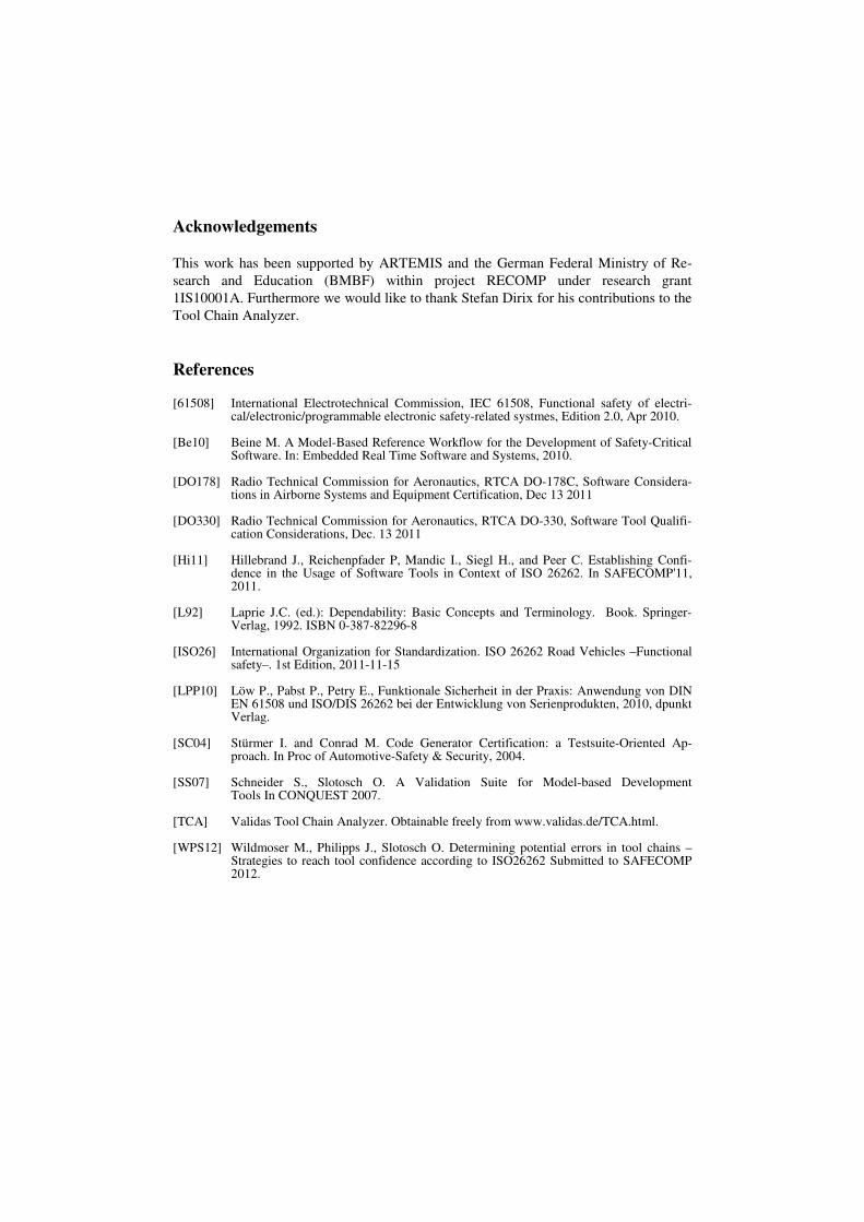
Acknowledgements
This work has been supported by ARTEMIS and the German Federal Ministry of Re-
search and Education (BMBF) within project RECOMP under research grant
1IS10001A. Furthermore we would like to thank Stefan Dirix for his contributions to the
Tool Chain Analyzer.
References
[61508] International Electrotechnical Commission, IEC 61508, Functional safety of electri-cal/electronic/programmable electronic safety-related systmes, Edition 2.0, Apr 2010.
[Be10] Beine M. A Model-Based Reference Workflow for the Development of Safety-Critical
Software. In: Embedded Real Time Software and Systems, 2010. [DO178] Radio Technical Commission for Aeronautics, RTCA DO-178C, Software Considera-
tions in Airborne Systems and Equipment Certification, Dec 13 2011 [DO330] Radio Technical Commission for Aeronautics, RTCA DO-330, Software Tool Qualifi-
cation Considerations, Dec. 13 2011 [Hi11] Hillebrand J., Reichenpfader P, Mandic I., Siegl H., and Peer C. Establishing Confi-
dence in the Usage of Software Tools in Context of ISO 26262. In SAFECOMP'11, 2011.
[L92] Laprie J.C. (ed.): Dependability: Basic Concepts and Terminology. Book. Springer-
Verlag, 1992. ISBN 0-387-82296-8 [ISO26] International Organization for Standardization. ISO 26262 Road Vehicles –Functional
safety–. 1st Edition, 2011-11-15 [LPP10] Löw P., Pabst P., Petry E., Funktionale Sicherheit in der Praxis: Anwendung von DIN
EN 61508 und ISO/DIS 26262 bei der Entwicklung von Serienprodukten, 2010, dpunkt Verlag.
[SC04] Stürmer I. and Conrad M. Code Generator Certification: a Testsuite-Oriented Ap-
proach. In Proc of Automotive-Safety & Security, 2004. [SS07] Schneider S., Slotosch O. A Validation Suite for Model-based Development
Tools In CONQUEST 2007. [TCA] Validas Tool Chain Analyzer. Obtainable freely from www.validas.de/TCA.html. [WPS12] Wildmoser M., Philipps J., Slotosch O. Determining potential errors in tool chains –
Strategies to reach tool confidence according to ISO26262 Submitted to SAFECOMP 2012.