Embed Size (px)
Citation preview

Disclosure to Promote the Right To Information
Whereas the Parliament of India has set out to provide a practical regime of right to information for citizens to secure access to information under the control of public authorities, in order to promote transparency and accountability in the working of every public authority, and whereas the attached publication of the Bureau of Indian Standards is of particular interest to the public, particularly disadvantaged communities and those engaged in the pursuit of education and knowledge, the attached public safety standard is made available to promote the timely dissemination of this information in an accurate manner to the public.
इंटरनेट मानक
“!ान $ एक न' भारत का +नम-ण”Satyanarayan Gangaram Pitroda
“Invent a New India Using Knowledge”
“प0रा1 को छोड न' 5 तरफ”Jawaharlal Nehru
“Step Out From the Old to the New”
“जान1 का अ+धकार, जी1 का अ+धकार”Mazdoor Kisan Shakti Sangathan
“The Right to Information, The Right to Live”
“!ान एक ऐसा खजाना > जो कभी च0राया नहB जा सकता है”Bhartṛhari—Nītiśatakam
“Knowledge is such a treasure which cannot be stolen”
“Invent a New India Using Knowledge”
है”ह”ह
IS/ISO 5170 (1977): Machine Tools - Lubrication Systems[PGD 3: Machine Tools]


/
IS/IS0 5176 : 1977
v?Tfhw
Indian Standard
MACHINE TOOLS - LUBRICATION SYSTEMS
ES 25.080 : 21,260
0 BIS 1995
BUREAU OF INDIAN STANDARDS MANAK BHAVAN, 9, BAHADUR SHAH, ZAFAR MARG
NEW DELHI 110002
December 1995 Price Group 4

Machine Tools Sectional Committee, PE 03
NATIONAL FOREWORD
This Indian Standard which is identical with IS0 5170-l 977 ‘Machine tools - Lubrication systems’ issued by the International Organization for Standardization (ISO), was adopted by the Bureau of Indian Standards on the recommendations of the Machine Tool Basics and Modular Units Sectional Committe now titled as Machine Tools Sectional Committee and approval of the Production Engineering Division Council.
The text of the IS0 standard has been approved as suitable for publicatioin as Indian Standard without deviations. Certain conventions are however not identical to those used’in Indian Standards. Attention is particularly drawn to the following:
a) Wherever the words ‘International Standard’ appear referring to this standard, they should be read as ‘Indian Standard’.
b) Comma (,) has been used as a decimal marker while in Indian Standard, the current practice is to use a point (.) as the decimal marker.
c) Inch dimensions and capacity in terms of ‘gal U.S.’ as given in the International Standard have not been included as the same are not prevalent in the country.
In this adopted standard, reference appears to certain International Standards for one of which Indian Standard also exists. The corresponding Indian Standard which is to be substituted in its place is listed along with its degree of equivalence for the edition indicated.
International Standard Indian Standard Degree of Correspondence
IS0 1219-l 976 Fluid power systems IS 7513 : 1974 Graphic symbols for Equivalent and components - Graphic sym- fluid power systems bols
There are no corresponding Indian Standards available in regard to following IS0 standards:
IS0 3498-l 986 Lubricants for machine tools
IS0 5169-l 977 Machine tools - Presentation of lubrication instructions
The technical committee responsible for the preparation of this standard has reviewed the provisions of the above mentioned IS0 standards and has decided that they are acceptable for use in conjunction with this standard.

IS/IS0 5170 : 1977
lndian Standard
MACHINE TOOLS - LUBRICATION SYSTEMS
1 SCOPE AND FIELD OF APPLICATION
This lnternatioinal Standard establishes - a classification of the various lubrication
systems for machine tools; - specification regarding the components; - control and monitoring methods; - system lay-out practice; - system maintenance.
It is intended to give guidance to manufacturers and users of machine tools, with a view to rationalizing the method of lubrication.
This lnternatioinal Standard may be applied to other general types of machinery.
2 REFERENCES
IS0 1219, Fluidpower systems and components - Graphic symbols.
IS0 3498, Lubricants for machine tools.‘)
IS0 5169, Machine too/s - Presentation of lubrication instructions. *)
3 DEFINITIONS
For the purposes of this International Standard, the following definitions apply.
3.1 lubrication point : The point where lubricant is fed in order to lubricate a bearing surface.
3.2 action polnt: Any point in a lubrication sys- tem where, in general, an external action should be carried out to ensure the correct operation of the system. For example, filling with lubricant (nipples or reservoirs, etc), actuation of a lever, etc.
4 METHODS OF LUBRICATION (See the annexes)
4.1 Total loss system
The lubricant is supplied to the lubrication point and after use it goes to waste.
4.2 Circulating system
The lubricant is fed to the lubrication points and is then returned to the reservoir for further use. 1) At present at the stage of draft (Revision of ISO/TR 3498-
1 974).
2) At present at the stage of draft.
4.3 Hydrostatic system
Fluid lubricatiion in which surfaces, moving or stationary, are separated by a fluid introduced between them by an external pressure.
.5 ?‘YPES OF SYSTEM (See the annexes)
5.1 lndlvldual point lubrlcatlon
Individual point lubrication is that type of lubrica- tion carried out by manual portable equipment.
Individual point lubrication may be used on simple machines or where there are only about 10 points requiring lubrication at intervals of approximately 50 h.
5.2 Centralized system
A centralized system is one in which two or more lubrication points on a machine are served with the same lubricant from a common source. Centralized systems are particularly applicable if the machine is intended for mass production or if the machine is complex or expensive.
Centralized systems may be
a) manually operated:
b) semi-automatic in operation, pumps being manually actuated;
C) fully automatic in operation.
5.2.1 Restrictor type
In restrictor type systems, the quantity of lubricant distributed is proportional to the pres- sure and to the size of the orifice.
5.2.2 Single-line type
In single-line type systems, the lubricant is sup- plied under interm,ittent pressure (direct or delayed) through single-line pipework to the in- jectors which feed the lubricant to the various lubrication points. It is a characteristic of the single-line type that the main pipework must be depressurized after the lubrication shot. This is necessary for the functioning of the metering devices.
5.2.3 Two-line type
In two_!ine type systems, the lubricant is alter- nately forced via a directional control valve to
1

each of two main pipe lines to which metering The reservoir shall be marked with the normal devices are connected at intervals. The metering working, maximum and minimum levels and devices are operated by the alternate rise and fall the total reservoir capacity shall be clearly in lubricant pressure in.the main lines, allowing indicated. the metered quantity of lubricant to be delivered to the lubrication point.
6.2.1.2 All reservoirs with capacities greater than 0,5 I shall befitted with a visual level in-
5.2.4 Multi-line type dicator so that the actual level in the tank can be easily checked at any time from the maximum to
In multi-line type systems, the lubricant is the minimum level delivered in metered quantities from a number of outlets of one pump: An individual pipe runs 6.2.1.3 In an automatic centralized total loss from each outlet to the respective lubrication system, an alarm signal control of the low level is point. needed.
5.2.5 Progressive plunger type
In systems of this type, the quantity of lubricant is supplied to the lubrication points by metering devices, pressure operated, in a predetermined sequence.
5.2.6 Oil mist/Aerosol type
In this type of system, minute particles of lubricat- ing oil, suspended in an air stream, are generated at a central point, and piped to the lubrication points where the oil mist is converted back to useful oil through specially designed devices.
5.2.7 Combined system
Combinations of the various types of system described above are possible if required by the machine design.
6 SPECIFICATION OF COMPONENT PARTS
6.1 Nipples and Individual lubricators
Nipples shall be of the direct-injection type (preferably of hydraulic type) with portable pump. Nipples and individual lubricators shall be screwed into holes threaded in accordance with International Standards.
6.2 Reservoirs
6.2.1 Oil reservoirs
6.2.1.4 In circulating systems, means shall be provided to stop operation of the machine when the lubricant falls below an acceptable level. (See 6.8.4.)
6.2.1.5All reservoirs with capacities greater than 3 I must be fitted with a mesh strainer in the filler hole fine enough but of adequate size to permit rapid filling consistent with the viscosity of the lubricant. It should have a cap to prevent the accidental introduction of foreign matter. An air vent shall be provided and this may be part of the cap or cover.
6.2.1.6 The filter cap shall be tamperproof and fitted with a device to prevent its loss.
6.2.1.7 All reservoirs of a capacity greater than 3 I shall have a tamperproof drain plug to ensure rapid and complete draining. Thread shall con- form to International Standards.
6.2.1.8 Protective coatings for the internal sur- faces shall be compatible with lubricants.
6.2;l.g Reservoirs shall have an accessible opening to peimit internal cleaning and main- tenace.
6.2.1 .lO In circulating-system reservoirs, the pipe ends shall be immersed in the oil below the minimum operational level.
6.2.1 .f The reservoir shall always have a In addition, thesuction and return pipe endsshall capacity such that be separated as much as possible to minimize
a) For total loss systems: the effect of foaming and/or of emulsion.
Refilling shall be only necessary after a mini- mum of 50 working hours.
6.2.1 .ll If electric heating is provided, the rating of the heating surface shall not normally exceed
b) For circulating systems: 12,5 kW/m2. Draining and cleaning shall only be neces- sary after a minimum of 1 000 working hours.
6 2 2 Grease reservoirs * -
Reservoirs shall be of sufficient capacity to 6.2.2-i Grease reservoirs shall be fitted with contain all the fluid used in the system and to d dissipate excess heat generated, unless
evices to ensure positive pump prime.
fitted with devices (i.e,heat exchanger) to cool 6.2.2.2 Reservoirs shall be fitted with means for the lubricant. allowing air to escape during filling.
2

6.2.2.3 All reservoirs with capacities greater than 0,5 I shall be so designed that the actual level in the tank may be easily checked at any time from the maximum to the minimum levels.
6.2.2.4 The reservoir and the pump shall be integrally mounted.
6.2.2.5 Automatic systems shall have an alarm signal to indicate the low lubricant level.
6.2.2.6 The filler cap shall be tamperproof and fitted with a device to prevent its loss.
The filter connection shall incorporate a mesh strainer and the assembly shall permit rapid filling.
6.2.2.7 Large reservoirs shall be designed with adequate facilities for emptying and internal cleaning.
6.2.2.6 Protective coatings for the internal sur- faces shall be compatible with lubricants.
6.3 Pumps
6.3.1 Pumps may have the following types of drive:
- electric; - pneumatic; - hydraulic; - mechanical; - manual.
6.3.2 Pumps may be of single or multi-piston type, gear type, vane type or screw type.
6.3.3 The direction of rotation of the pump as well as the inlet and outlet ports shall be clearly indi- cated.
6.3.4 Plates showing the following data shall also be attached to the pump:
- name of manufacturer; - moder designation or identification num-
ber; - serial number (where applicable).
6.4 Piping
Flexible or rigid piping may be used and shall have the following features:
6.4.1 Flexible piping
6.4.1 .l Flexible piping shall be chemically inert to lubricants.
6.4.1.2 Flexible piping shall have a mechanical strength conistent with the maximum system operating pressure.
6.4.1.3 Flexible piping shall be able to sustain accidental overpressures without altering lubrication
IS/IS0 5170 : 1977
6.4.2 Rigid piping
6.4.2.1 Rigid piping shall be made of scale-free steel, plastic materials or any other suitable .material.
6.4.2.2 Where pipes are exposed to heat sour- cesgalvanized pipes shall be avoided. In addi- tion,if the pipes are in contact with cutting fluids containing active or uncombined sulphur, the use of copper pipes shall be avoided.
6.4.2.3 Inside diameters of pipes for grease shall not be less than 4 mm for main lines and 3 mm for feed lines.
6.4;3 Oil mistlaerosol SyStet?E
In the case of oil mist/aerosol systems, all types of piping shall have smooth walls and fiiings without a reduction of cross-sectional area.
6.5 Fittings
6.5.1 Fittings shall be selected to suit the system, the pressure and the types of piping used.
6.5.2 Threads shall conform to International Standards.
6.6 Filters
6.6.1 Whatever the type of system, the lubricant shall not contain impurities which may damage the machine tool or the system components.
6.6.2 In the case of circulating or hydrostatic systems, it is advisableto provide a filter system (strainer or integral at the outlet of the pump) to prevent the lubricant in the reservoirs from be- coming contaminated, and in extreme cases to provide connections on the reservoir for centrifuging.
6.6.3 The filters shall not permit the passage of impurities and, therefore, means shall be provided to indicate that the filter is blocked.
6.7 Metering devices
The nominal quantity of lubricant or, in the case of adjustable devices, the maximum quantity delivered at each stroke by volumetric devices shall be shown on the device.
6.6 Control and safety devices
6.6.1 Control systems may be
- -
continuous. programmed intermittent independent of machine cyc.!e.
- cyclic intermittent dependent on machine cycle.
6.8.2 Each system shall be fitted with control devices which indicate abnormal lubrication sys- tem pressures.
3.

IS/IS0 5170 : 1977
6.8.3 Where required, devices may also be fitted which will indicate other system defects and will localize them.
This may particularly apply to important machines where downtime is long and expen- sive.
6.8.4 Where necessary, means may be provided to stop the machine, after the indication of a failure has been given, so as to avoid serious damage to the machine, the tooling and the operators.
6.8.5 Pressure gauges used in lubrication sys- tems shall be fitted with dampers or shall be of the oil-bath type.
6.9 Electric motors and electrical equipment
Electric motors and all electrical equipment shall conform to the appropriate IEC Publications.
7 SYSTEM COMPONENTS - LAYOUT PRACTICE
7.1 Lubrication systems
7.1 .l’ System design shall ensure the complete separation of cutting fluid and lubrication sys- tems.
7.1.2 Hydraulic and lubrication systems shall only be combined when the oil selected is suitable for both applications, and provided that care is taken to remove impurities.
7.2 Nipples and individual lubricators
7.2.1 These shall be placed in easily accessible positions.
7.2.2 Points being supplied with the same lubricant may advantageously be mounted on a common block which cati be easily reached and shall be situated between 500 mm and 1200 mm above working level.
7.2.3 The use of wick-oiling, drip-feed, Stauffer and other special types of lubricator is to be discouraged.
7.3 Reservoirs .
7.3.1 Manually filled reservoirs shall be posi- tioned with the filler connection easily accessible and situated between 500 mm and 1 200 mm above working level.
7.3.2 Drain plugs shall be easily accessible and allow the reservoir to be completely and easily drained.
Where openings are provided for internal clean- ing, they shall be easily accessible.
7.3.3 Level indicators shall be provided which are visible to the person responsible for filling the reservoir.
7.3.4 For filling the reservoir with grease, the use of an ancillary pump fiied with suitable strainers is highly advisable.
7.4 Pumps
7.4.1 Pumps may be mounted inside or outside the reservoir but shall be adequately protected and readily accessible for adjustment and main- tenance purposes.
7.4;2 Manual pumps shall be positioned in such a manner that they may be easily operated.
7.5 Piping
7.51 Piping shall be properly fastened, ade- quately protected, and positioined so that it does not obstruct or render inaccessible other machine components.
7.5.2 Pipework shall not be subject to stress other than that due to internal pressure, and shall not be used to support large system com- ponents.
7.5.3 All open pipe ends shall be suitably covered and sealed throughout storage, transport and assembly periods and shall be thoroughly cleaned before running.
The use of sealing compounds is to be dis- couraged.
7.5.4 Pipework layout shall be such that losses of pressure are limited, and that there is no excessive restriction to flow.
7.5.5 In circulating systems, return pipework shall have an adequate cross-sectional area, larger than the feed lines.
7.5.6 In oil mist/aerosol systems, all main pipework shall be installed so that it slopes back to the reservoir, and means shall be provided to prevent entrapment of any residual oil, for ex- ample by drilling a hole about 1 mm diameter at the bottom of down loops. If flexible pipes are used, down loops shall be avoided.
7.5.7 Sharp bends on pipework shall be avoided whenever possible.
7.5.8 Flexible hoses shall be installed so as to avoid any excessive torsional stresses.
7.6 Fittings
All fittings shall be positioned so that they are accessible.
4

IS/IS0 5170 : 1977
7.7 Filters 8.2 The machine tool manufacturer shall take
7.7.1 All filters shall be located so that they are special care to avoid any accidental mixing of
easily accessible. coolants, cutting fluids and lubricants.
7.7.2 Filters shall be mounted to prevent air 9 SAFETY OF LUBRICATION PERSONNEL entrapment.
7.8.3 Adjustable metering devices shall be easily
7.7.3 Grease strainers should be installed on the
accessible.
delivery side of the pump.
7.8 Metering devices
7.8.1 Each metering device outlet shall supply only one lubrication point except in the case of oil mist/aerosol systems.
7.8.2 Metering devices shall be situated as close as possible to the lubrication point.
All action points shall be easily accessible and situated so as not to cause a safety hazard.
If this is impossible, the personnel shall be protected by adequate guards in conformity with safety regulations.
10 DOCUMENTS TO BE SUPPLIED BY THE MACHINE TOOL MANUFACTURER
the manufacturer’s or supplier’s part number and specification.
10.1 List of components together with details of
7.9 Control and safety devices 10.2 Lubrication instructions complying with IS0
7.9.1 All visual indicators shall be positioned 5169 and details of amount of lubricant used on
where they can be easily seen by the operator, -an hourly basis.
for example pressure gauges, level indicators, flow meters, etc.
10.3 The method of system operation as defined in 6.8.1.
7.9.2 In circulating systems fitted with restrictor- type metering devices, it is desirable to fit visual 10.4 Instructions for operation and maintenance flow indicators. of the lubrication system.
7.10 Action points 11 TESTING AND ACCEPTANCE
All action points shall be suitably labelled complying with IS0 5169.
The system shall be in compliance with - this International Standard;
8 LUBRICANTS - the stated performance characteristics;
8.1 Lubricants shall be selected by the machine tool manufacturer from IS0 3498.
- safety standards; - any special requirements agreed be-
tween the supplier and the purchaser.

IS/IS0 5170 : 1977
ANNEX A
CLASSIFICATION OF LUBRICATION SYSTEMS
LUBRICATION SYSTEMS
INDIVIDUAL POINT
Oil Grease
CENTFtALlZED
~NG SYSTEM TOTAL LOSS SYSTEM -
Restrictor type 1 Lubricant 1 1 Lubricant 1 Restrictor type I
Oil I
Multi-line 1 Lubricant 1 1 Lubricant 1
~ Oil
M SA A Grease
I Oil mist/aerosol Lubricant
- - I A Oil I
Oil
- - SA A
I Lubricant 1 Singlaline I
1 Lubricant 1 Two-line I
Oil
- - SA A
Multi-line I Oil
- - SA A
1 Lubricant 1 Progressive plunger 1
Oil
- - SA A
M = Manual
SA = Semi-automatic
A = Automatic
6

lsnso 5170 : 1977
ANNEX B DIAGRAMS OF CENTRALIZED LUBRICATION SYSTEMS ‘)
Total loss systems
99 999
AA bb
B’P N KP
M 0 l-4’ V B
J
Circulating systems j
BPNA KP
A Pump with lubricant resewok
B Lubrication point C Restrictor D Single-line metering device E Relief line F PressureI line G Relief valve H Main line
Description
Feed line ^. ulrectwnal control valve 412 Compressed-air line Secondary feed line Oil-mist-lubricating unit
Progressive plunger metering device Return line Two-line metering device Condenser
1) These diagrams are simplified and given as an example.
7
IS/IS0 5170:19?7
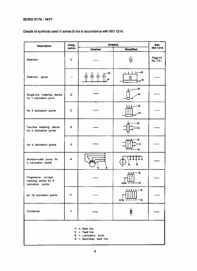
Details of symbols used in annex B not in accordance with IS0 1219.
Description Desig- nation
SYMBOL See
Detalled I
Simplified IS0 1218
Restrictor c )I(
Page 13 No. 7.5.1
Restrictor group - )I( )I( 11 IL JqK -
K
Single-line metering device D H
for 1 lubrication point 5 1’
K
fo! 3 lubrication points D
AK H
K
Two-line metering device s
for 2 lubrication points +
l-l
for 6 lubrication points S
4IE
Multiple-outlet pump for
5 lubrication points A gB $$$ 1
Progressive plunger
metering device for 6
lubrication points 4F H/N K
4#E
K
for 10 lubrication points P
H/N K
Condenser V
H = Main line
K = Feed line
B = Lubrication point
N = Secondary feed line
8

Bureau of Indian Standards
BIS is a statutory institution established under the Bureau of Indian Standards Act, I986 to promote harmonious development of the activities of standardization, marking and quality certification of goods and attending to connected matters in the country.
Copyright
BIS has the copyright of all its publications. No part of these publications may be reproduced in any form without the prior permission in writing of BIS. This does not preclude the free use, in the course of implementing the standard, of necessary details, such as symbols and sizes, type or grade designations. Enquiries relating to copyright be addressed to the Director (Publications), BIS.
Review of Indian Standards
Amendments are issued to standards as the need arises on the basis of comments. Standards are also reviewed periodically; a standard along with amendments is reaffirmed when such review indicates that no changes are needed; if the review indicates that changes are needed, it is taken up for revision. Users of Indian Standards should ascertain that they are in possession of the latest amendments or edition by referring to the latest issue of ‘BIS Handbook’ and ‘Standards Monthly Additions’.
This Indian Standard has been developed from Dot : No. PE 03 ( 0101).
Amendments Issued Since Publication
Amend No. Date of Issue Text Affected I
BUREAU OF INDIAN STANDARDS
Headquarters:
Manak Bhavan, 9 Bahadur Shah Zafar Marg, New Delhi 110002 Telegrams : Manaksanstha Telephones : 3310131,33113 75,37194 02 (Common to all offices)
Regional Offices : Telephone
Central : Manak Bhavan, 9 Bahadur Shah Zafar Marg 33166 17 NEW DELHI 110002 335 38 41
Eastern : l/14 C. LT. Scheme VII M, V. I. P. Road, Maniktola 37 84 99,37 85 61 CALCUTTA 700054 37 86 26,37 9120
Northern : SC0 335-336, Sector 34-A CHANDIGARH 160022 60 38 43 60 20 25
Southern : C. I. T. Campus, IV Cross Road, MADRAS 600113 235 02 16,235 04 42 235 15 19,235 23 15
Western : Manakalaya, E9 MIDC, Marol, Andheri (East) 832 92 95,832 78 58 BOMBAY 400093 832 78 91,832 78 92
Branches : AHMADABAD. BANGALORE. BHOPAL. BHUBANESHWAR. COIMBATORE. FARIDABAD. GHAZIABAD: GUWAHATI. HYDERABAD. JAIPUR. KANPUR. LUCKNOW. PATNA. THIRUVANANTHAPURAM.
Printed at Printograph, New Delhi-5 (INDIA