Embed Size (px)
Citation preview

Isilon OneFS 8.2.1CLI Administration Guide
8.2.1
May 2020

Notes, cautions, and warnings
NOTE: A NOTE indicates important information that helps you make better use of your product.
CAUTION: A CAUTION indicates either potential damage to hardware or loss of data and tells you how to avoid the
problem.
WARNING: A WARNING indicates a potential for property damage, personal injury, or death.
© 2016 - 2020 Dell Inc. or its subsidiaries.All rights reserved. Dell, EMC, and other trademarks are trademarks of Dell Inc. or itssubsidiaries. Other trademarks may be trademarks of their respective owners.

1 Introduction to this guide............................................................................................................ 22About this guide...................................................................................................................................................................22Isilon scale-out NAS overview........................................................................................................................................... 22Where to go for support.....................................................................................................................................................22
2 Isilon scale-out NAS....................................................................................................................23OneFS storage architecture...............................................................................................................................................23Isilon node components...................................................................................................................................................... 23Internal and external networks.......................................................................................................................................... 24Isilon cluster..........................................................................................................................................................................24
Cluster administration................................................................................................................................................... 24Quorum........................................................................................................................................................................... 25Splitting and merging.................................................................................................................................................... 25Storage pools................................................................................................................................................................. 25
The OneFS operating system............................................................................................................................................ 26Data-access protocols.................................................................................................................................................. 26Identity management and access control...................................................................................................................26
Structure of the file system............................................................................................................................................... 27Data layout......................................................................................................................................................................27Writing files..................................................................................................................................................................... 27Reading files................................................................................................................................................................... 28Metadata layout.............................................................................................................................................................28Locks and concurrency.................................................................................................................................................28Striping............................................................................................................................................................................28
Data protection overview...................................................................................................................................................28N+M data protection.................................................................................................................................................... 29Data mirroring................................................................................................................................................................ 29The file system journal.................................................................................................................................................. 30Virtual hot spare (VHS)................................................................................................................................................ 30Balancing protection with storage space................................................................................................................... 30
Data compression................................................................................................................................................................30VMware integration............................................................................................................................................................ 30Software modules................................................................................................................................................................ 31
3 Introduction to the OneFS command-line interface....................................................................... 32OneFS command-line interface overview........................................................................................................................32Syntax diagrams.................................................................................................................................................................. 32Universal options................................................................................................................................................................. 33Command-line interface privileges.................................................................................................................................... 33SmartLock compliance command permissions................................................................................................................34OneFS time values.............................................................................................................................................................. 35
4 General cluster administration.....................................................................................................37General cluster administration overview...........................................................................................................................37
Contents
Contents 3

User interfaces.....................................................................................................................................................................37Connecting to the cluster...................................................................................................................................................38
Log in to the web administration interface................................................................................................................ 38Open an SSH connection to a cluster.........................................................................................................................38
Licensing...............................................................................................................................................................................38Software licenses.......................................................................................................................................................... 39Hardware tiers................................................................................................................................................................39License status................................................................................................................................................................ 39Adding and removing licenses......................................................................................................................................40Activating trial licenses.................................................................................................................................................. 41
Certificates............................................................................................................................................................................41Replacing or renewing the TLS certificate.................................................................................................................42Verify an SSL certificate update..................................................................................................................................45TLS certificate data example....................................................................................................................................... 45
Cluster identity.....................................................................................................................................................................45Set the cluster name ....................................................................................................................................................46
Cluster contact information............................................................................................................................................... 46Cluster date and time..........................................................................................................................................................46
Set the cluster date and time...................................................................................................................................... 46Specify an NTP time server..........................................................................................................................................47
SMTP email settings........................................................................................................................................................... 47Configure SMTP email settings .................................................................................................................................. 47View SMTP email settings............................................................................................................................................48
Configuring the cluster join mode..................................................................................................................................... 48Specify the cluster join mode ......................................................................................................................................48
File system settings.............................................................................................................................................................48Specify the cluster character encoding......................................................................................................................49Enable or disable access time tracking ...................................................................................................................... 49
Data compression settings and monitoring......................................................................................................................49Data compression terminology.................................................................................................................................... 49Enable or disable data compression............................................................................................................................ 50View compression statistics.........................................................................................................................................50
Events and alerts.................................................................................................................................................................52Events overview............................................................................................................................................................ 52Alerts overview.............................................................................................................................................................. 52Channels overview........................................................................................................................................................ 52Event groups overview.................................................................................................................................................53Viewing and modifying event groups..........................................................................................................................53View an event................................................................................................................................................................ 55Managing alerts............................................................................................................................................................. 55Managing channels........................................................................................................................................................56Maintenance and testing.............................................................................................................................................. 58
Security hardening.............................................................................................................................................................. 59STIG hardening profile.................................................................................................................................................. 60Apply a security hardening profile............................................................................................................................... 60Revert a security hardening profile.............................................................................................................................. 61View the security hardening status..............................................................................................................................61
Cluster monitoring...............................................................................................................................................................62Monitor the cluster........................................................................................................................................................62View node status........................................................................................................................................................... 62
4 Contents

Monitoring cluster hardware..............................................................................................................................................62View node hardware status..........................................................................................................................................62Chassis and drive states............................................................................................................................................... 63Check battery status.....................................................................................................................................................64SNMP monitoring.......................................................................................................................................................... 64
Cluster maintenance........................................................................................................................................................... 67Replacing node components........................................................................................................................................ 67Upgrading node components....................................................................................................................................... 67Automatic Replacement Recognition (ARR) for drives............................................................................................67Managing drive firmware..............................................................................................................................................69Managing cluster nodes.................................................................................................................................................71Upgrading OneFS.......................................................................................................................................................... 73
Remote support................................................................................................................................................................... 73Configuring Secure Remote Services support...........................................................................................................73Remote support scripts.................................................................................................................................................77Enable and configure Secure Remote Services support .........................................................................................80Disable (E)SRS support.................................................................................................................................................81View (E)SRS configuration settings............................................................................................................................ 81
5 Access zones............................................................................................................................. 82Access zones overview ..................................................................................................................................................... 82Base directory guidelines....................................................................................................................................................82Access zones best practices..............................................................................................................................................83Access zones on a SyncIQ secondary cluster................................................................................................................. 83Access zone limits............................................................................................................................................................... 83Quality of service.................................................................................................................................................................84Zone-based Role-based Access Control (zRBAC)......................................................................................................... 84
Non-System access zone privileges........................................................................................................................... 84Built-in roles in non-System zones..............................................................................................................................85
Zone-specific authentication providers............................................................................................................................85Managing access zones......................................................................................................................................................86
Create an access zone..................................................................................................................................................86Assign an overlapping base directory..........................................................................................................................86Manage authentication providers in an access zone................................................................................................ 86Associate an IP address pool with an access zone................................................................................................... 87Modify an access zone..................................................................................................................................................87Delete an access zone...................................................................................................................................................87View a list of access zones...........................................................................................................................................87Create one or more access zones...............................................................................................................................88Create local users in an access zone.......................................................................................................................... 88Access files through the RESTful Access to Namespace (RAN) in non-System zones......................................89
6 Authentication........................................................................................................................... 90Authentication overview.....................................................................................................................................................90Authentication provider features...................................................................................................................................... 90Security Identifier (SID) history overview.........................................................................................................................91Supported authentication providers.................................................................................................................................. 91Active Directory....................................................................................................................................................................91LDAP..................................................................................................................................................................................... 92
Contents 5

NIS.........................................................................................................................................................................................92Kerberos authentication..................................................................................................................................................... 92
Keytabs and SPNs overview........................................................................................................................................93MIT Kerberos protocol support................................................................................................................................... 93
File provider..........................................................................................................................................................................93Local provider.......................................................................................................................................................................93Multi-factor Authentication (MFA)...................................................................................................................................94Multi-instance active directory..........................................................................................................................................94LDAP public keys................................................................................................................................................................. 94Managing Active Directory providers............................................................................................................................... 94
Configure an Active Directory provider...................................................................................................................... 94Modify an Active Directory provider...........................................................................................................................95Delete an Active Directory provider............................................................................................................................95
Managing LDAP providers..................................................................................................................................................95Configure an LDAP provider........................................................................................................................................ 95Modify an LDAP provider............................................................................................................................................. 96Delete an LDAP provider.............................................................................................................................................. 96
Managing NIS providers..................................................................................................................................................... 96Configure an NIS provider............................................................................................................................................96Modify an NIS provider.................................................................................................................................................96Delete an NIS provider.................................................................................................................................................. 97
Managing MIT Kerberos authentication........................................................................................................................... 97Managing MIT Kerberos realms................................................................................................................................... 97Managing MIT Kerberos providers..............................................................................................................................98Managing MIT Kerberos domains.............................................................................................................................. 100Managing SPNs and keys............................................................................................................................................ 101
Managing file providers..................................................................................................................................................... 102Configure a file provider.............................................................................................................................................. 102Generate a password file............................................................................................................................................ 103Modify a file provider................................................................................................................................................... 103Delete a file provider.................................................................................................................................................... 103Password file format....................................................................................................................................................103Group file format.......................................................................................................................................................... 104Netgroup file format.................................................................................................................................................... 104
Managing local users and groups.....................................................................................................................................105View a list of users and groups by provider..............................................................................................................105Create a local user....................................................................................................................................................... 105Create a local group.....................................................................................................................................................105Naming rules for local users and groups................................................................................................................... 105Configure or modify a local password policy............................................................................................................ 105Local password policy settings...................................................................................................................................106Modify a local user....................................................................................................................................................... 107Modify a local group.....................................................................................................................................................107Delete a local user........................................................................................................................................................ 107Delete a local group......................................................................................................................................................107
SSH Authentication and Configuration........................................................................................................................... 108Pre-requisites for Multi-factor Authentication (MFA)............................................................................................108SSH configuration using password............................................................................................................................ 108SSH Configuration using public keys......................................................................................................................... 109
6 Contents

7 Administrative roles and privileges.............................................................................................. 110Role-based access..............................................................................................................................................................110Roles..................................................................................................................................................................................... 110
Custom roles..................................................................................................................................................................110Built-in roles....................................................................................................................................................................111
Privileges.............................................................................................................................................................................. 114Supported OneFS privileges........................................................................................................................................ 114Data backup and restore privileges............................................................................................................................ 116Command-line interface privileges..............................................................................................................................117
Managing roles................................................................................................................................................................... 120View roles...................................................................................................................................................................... 120View privileges.............................................................................................................................................................. 120Create and modify a custom role................................................................................................................................121Delete a custom role.....................................................................................................................................................121Add a user to built-in roles........................................................................................................................................... 121Create a new role and add a user.............................................................................................................................. 123
8 Identity management................................................................................................................ 125Identity management overview........................................................................................................................................125Identity types...................................................................................................................................................................... 125Access tokens.................................................................................................................................................................... 126Access token generation...................................................................................................................................................126
ID mapping.....................................................................................................................................................................127User mapping................................................................................................................................................................128On-disk identity............................................................................................................................................................ 129
Managing ID mappings...................................................................................................................................................... 130Create an identity mapping.........................................................................................................................................130Modify an identity mapping........................................................................................................................................ 130Delete an identity mapping......................................................................................................................................... 130View an identity mapping............................................................................................................................................. 131Flush the identity mapping cache............................................................................................................................... 131View a user token..........................................................................................................................................................131Configure identity mapping settings.......................................................................................................................... 132View identity mapping settings.................................................................................................................................. 132
Managing user identities................................................................................................................................................... 132View user identity.........................................................................................................................................................133Create a user-mapping rule.........................................................................................................................................133Merge Windows and UNIX tokens.............................................................................................................................134Retrieve the primary group from LDAP.................................................................................................................... 135Mapping rule options................................................................................................................................................... 135Mapping rule operators............................................................................................................................................... 136
9 Home directories...................................................................................................................... 138Home directories overview............................................................................................................................................... 138Home directory permissions............................................................................................................................................. 138Authenticating SMB users................................................................................................................................................ 138Home directory creation through SMB...........................................................................................................................139
Create home directories with expansion variables.................................................................................................. 139
Contents 7

Create home directories with the --inheritable-path-acl option............................................................................ 140Create special home directories with the SMB share %U variable....................................................................... 140
Home directory creation through SSH and FTP.............................................................................................................141Set the SSH or FTP login shell ................................................................................................................................... 141Set SSH/FTP home directory permissions............................................................................................................... 141Set SSH/FTP home directory creation options....................................................................................................... 142Provision home directories with dot files.................................................................................................................. 143
Home directory creation in a mixed environment.......................................................................................................... 143Interactions between ACLs and mode bits.....................................................................................................................143Default home directory settings in authentication providers....................................................................................... 144Supported expansion variables.........................................................................................................................................144Domain variables in home directory provisioning........................................................................................................... 145
10 Data access control..................................................................................................................146Data access control overview.......................................................................................................................................... 146ACLs.................................................................................................................................................................................... 146UNIX permissions............................................................................................................................................................... 147Mixed-permission environments...................................................................................................................................... 147
NFS access of Windows-created files.......................................................................................................................147SMB access of UNIX-created files............................................................................................................................ 147
Managing access permissions.......................................................................................................................................... 147View expected user permissions................................................................................................................................ 147Configure access management settings................................................................................................................... 148Modify ACL policy settings......................................................................................................................................... 149Run the PermissionsRepair job................................................................................................................................... 149
11 File sharing..............................................................................................................................150File sharing overview......................................................................................................................................................... 150
Mixed protocol environments.....................................................................................................................................150Write caching with SmartCache.................................................................................................................................151
SMB......................................................................................................................................................................................151SMB shares in access zones...................................................................................................................................... 152SMB Multichannel........................................................................................................................................................152SMB share management through MMC...................................................................................................................153SMBv3 encryption....................................................................................................................................................... 154SMB server-side copy................................................................................................................................................. 155SMB continuous availability........................................................................................................................................ 155SMB file filtering...........................................................................................................................................................156Symbolic links and SMB clients.................................................................................................................................. 156Anonymous access to SMB shares............................................................................................................................157Managing SMB settings.............................................................................................................................................. 157Managing SMB shares................................................................................................................................................ 159
NFS...................................................................................................................................................................................... 163NFS exports.................................................................................................................................................................. 163NFS aliases....................................................................................................................................................................164NFS log files.................................................................................................................................................................. 164Managing the NFS service..........................................................................................................................................164Managing NFS exports................................................................................................................................................165Managing NFS aliases..................................................................................................................................................167
8 Contents

FTP...................................................................................................................................................................................... 169View FTP settings........................................................................................................................................................169Enable FTP file sharing................................................................................................................................................ 170Configure FTP file sharing...........................................................................................................................................170
HTTP and HTTPS.............................................................................................................................................................. 170Enable and configure HTTP........................................................................................................................................ 170Enable HTTPS through the Apache service.............................................................................................................. 171Disable HTTPS through the Apache service............................................................................................................. 171
12 File filtering.............................................................................................................................172File filtering in an access zone.......................................................................................................................................... 172Enable and configure file filtering in an access zone..................................................................................................... 172Disable file filtering in an access zone..............................................................................................................................172View file filtering settings.................................................................................................................................................. 173
13 Auditing and logging.................................................................................................................174Auditing overview...............................................................................................................................................................174Syslog...................................................................................................................................................................................174
Syslog forwarding.........................................................................................................................................................175Protocol audit events........................................................................................................................................................ 175Supported audit tools........................................................................................................................................................ 175Delivering protocol audit events to multiple CEE servers.............................................................................................175Supported event types......................................................................................................................................................176Sample audit log................................................................................................................................................................. 176Managing audit settings.................................................................................................................................................... 177
Enable protocol access auditing................................................................................................................................. 177Forward protocol access events to syslog .............................................................................................................. 178Enable system configuration auditing........................................................................................................................ 178Set the audit hostname............................................................................................................................................... 178Configure protocol audited zones.............................................................................................................................. 178Forward system configuration changes to syslog....................................................................................................179Configure protocol event filters................................................................................................................................. 179
Integrating with the Common Event Enabler................................................................................................................. 179Install CEE for Windows.............................................................................................................................................. 179Configure CEE for Windows.......................................................................................................................................180Configure CEE servers to deliver protocol audit events..........................................................................................181
Tracking the delivery of protocol audit events............................................................................................................... 181View the time stamps of delivery of events to the CEE server and syslog.......................................................... 181Display a global view of delivery of protocol audit events to the CEE server and syslog................................... 181Move the log position of the CEE forwarder............................................................................................................182View the rate of delivery of protocol audit events to the CEE server.................................................................. 182
14 Snapshots............................................................................................................................... 183Snapshots overview.......................................................................................................................................................... 183Data protection with SnapshotIQ.................................................................................................................................... 183Snapshot disk-space usage.............................................................................................................................................. 184Snapshot schedules........................................................................................................................................................... 184Snapshot aliases.................................................................................................................................................................184File and directory restoration............................................................................................................................................184
Contents 9

Best practices for creating snapshots............................................................................................................................ 185Best practices for creating snapshot schedules............................................................................................................185File clones............................................................................................................................................................................186
Shadow-store considerations.....................................................................................................................................186Snapshot locks................................................................................................................................................................... 186Snapshot reserve............................................................................................................................................................... 187SnapshotIQ license functionality...................................................................................................................................... 187Creating snapshots with SnapshotIQ.............................................................................................................................. 187
Create a SnapRevert domain......................................................................................................................................187Create a snapshot schedule....................................................................................................................................... 188Create a snapshot........................................................................................................................................................ 188Snapshot naming patterns..........................................................................................................................................188
Managing snapshots .........................................................................................................................................................190Reducing snapshot disk-space usage....................................................................................................................... 190Delete a snapshot......................................................................................................................................................... 191Modify snapshot attributes......................................................................................................................................... 191Modify a snapshot alias ...............................................................................................................................................191View snapshots............................................................................................................................................................. 191Snapshot information.................................................................................................................................................. 192
Restoring snapshot data................................................................................................................................................... 192Revert a snapshot .......................................................................................................................................................192Restore a file or directory using Windows Explorer.................................................................................................193Restore a file or directory through a UNIX command line...................................................................................... 193Clone a file from a snapshot....................................................................................................................................... 193
Managing snapshot schedules......................................................................................................................................... 194Modify a snapshot schedule ...................................................................................................................................... 194Delete a snapshot schedule ....................................................................................................................................... 194View snapshot schedules ........................................................................................................................................... 194
Managing snapshot aliases............................................................................................................................................... 195Configure a snapshot alias for a snapshot schedule............................................................................................... 195Assign a snapshot alias to a snapshot....................................................................................................................... 195Reassign a snapshot alias to the live file system......................................................................................................195View snapshot aliases..................................................................................................................................................195Snapshot alias information.......................................................................................................................................... 196
Managing with snapshot locks......................................................................................................................................... 196Create a snapshot lock................................................................................................................................................196Modify a snapshot lock expiration date.....................................................................................................................196Delete a snapshot lock.................................................................................................................................................197Snapshot lock information...........................................................................................................................................197
Configure SnapshotIQ settings ....................................................................................................................................... 197SnapshotIQ settings ................................................................................................................................................... 198
Set the snapshot reserve..................................................................................................................................................198Managing changelists........................................................................................................................................................ 199
Create a changelist...................................................................................................................................................... 199Delete a changelist.......................................................................................................................................................199View a changelist......................................................................................................................................................... 199Changelist information.................................................................................................................................................199
15 Deduplication with SmartDedupe.............................................................................................. 201Deduplication overview..................................................................................................................................................... 201
10 Contents

Deduplication jobs.............................................................................................................................................................. 201Data replication and backup with deduplication............................................................................................................202Snapshots with deduplication..........................................................................................................................................202Deduplication considerations........................................................................................................................................... 202Shadow-store considerations..........................................................................................................................................203SmartDedupe license functionality..................................................................................................................................203Managing deduplication....................................................................................................................................................203
Assess deduplication space savings .........................................................................................................................203Specify deduplication settings ..................................................................................................................................204View deduplication space savings ............................................................................................................................ 204View a deduplication report ...................................................................................................................................... 204Deduplication job report information.........................................................................................................................204Deduplication information...........................................................................................................................................205
16 Inline Data Deduplication......................................................................................................... 206Inline Data Deduplication overview................................................................................................................................. 206Inline deduplication interoperability................................................................................................................................. 208Considerations for using inline deduplication.................................................................................................................208Enable inline deduplication............................................................................................................................................... 208Verify inline deduplication is enabled.............................................................................................................................. 208View inline deduplication reports.....................................................................................................................................209Disable or pause inline deduplication...............................................................................................................................209Remove deduplication....................................................................................................................................................... 210Assess inline deduplication space savings.......................................................................................................................210Troubleshoot index allocation issues............................................................................................................................... 210
17 Data replication with SyncIQ..................................................................................................... 211SyncIQ data replication overview..................................................................................................................................... 211Replication policies and jobs.............................................................................................................................................. 211
Automated replication policies....................................................................................................................................212Source and target cluster association....................................................................................................................... 213Configuring SyncIQ source and target clusters with NAT......................................................................................213Full and differential replication....................................................................................................................................214Controlling replication job resource consumption.................................................................................................... 214Replication policy priority............................................................................................................................................ 215Replication reports.......................................................................................................................................................215
Replication snapshots........................................................................................................................................................215Source cluster snapshots............................................................................................................................................215Target cluster snapshots.............................................................................................................................................216
Data failover and failback with SyncIQ............................................................................................................................216Data failover..................................................................................................................................................................216Data failback..................................................................................................................................................................217SmartLock compliance mode failover and failback..................................................................................................217SmartLock replication limitations................................................................................................................................217
Recovery times and objectives for SyncIQ.....................................................................................................................218RPO Alerts.................................................................................................................................................................... 218
Replication policy priority.................................................................................................................................................. 219SyncIQ license functionality..............................................................................................................................................219Creating replication policies.............................................................................................................................................. 219
Contents 11

Excluding directories in replication.............................................................................................................................219Excluding files in replication....................................................................................................................................... 220File criteria options...................................................................................................................................................... 220Configure default replication policy settings ............................................................................................................221Create a replication policy........................................................................................................................................... 221Create a SyncIQ domain.............................................................................................................................................222Assess a replication policy ......................................................................................................................................... 222
Managing replication to remote clusters........................................................................................................................222Start a replication job.................................................................................................................................................. 223Pause a replication job ............................................................................................................................................... 223Resume a replication job ............................................................................................................................................223Cancel a replication job ..............................................................................................................................................223View active replication jobs .......................................................................................................................................223Replication job information ........................................................................................................................................224
Initiating data failover and failback with SyncIQ............................................................................................................224Fail over data to a secondary cluster .......................................................................................................................224Revert a failover operation.........................................................................................................................................225Fail back data to a primary cluster ........................................................................................................................... 225Run the ComplianceStoreDelete job in a Smartlock compliance mode domain..................................................226
Performing disaster recovery for older SmartLock directories...................................................................................226Recover SmartLock compliance directories on a target cluster .......................................................................... 226Migrate SmartLock compliance directories .............................................................................................................227
Managing replication policies........................................................................................................................................... 227Modify a replication policy .........................................................................................................................................228Delete a replication policy ..........................................................................................................................................228Enable or disable a replication policy ........................................................................................................................228View replication policies .............................................................................................................................................229Replication policy information ...................................................................................................................................229
Managing replication to the local cluster....................................................................................................................... 230Cancel replication to the local cluster ......................................................................................................................230Break local target association ...................................................................................................................................230View replication policies targeting the local cluster................................................................................................ 230Remote replication policy information ...................................................................................................................... 231
Managing replication performance rules.........................................................................................................................231Create a network traffic rule ..................................................................................................................................... 231Create a file operations rule .......................................................................................................................................231Modify a performance rule .........................................................................................................................................231Delete a performance rule ..........................................................................................................................................231Enable or disable a performance rule .......................................................................................................................232View performance rules .............................................................................................................................................232
Managing replication reports........................................................................................................................................... 232Configure default replication report settings ..........................................................................................................232Delete replication reports........................................................................................................................................... 233View replication reports .............................................................................................................................................233Replication report information................................................................................................................................... 234
Managing failed replication jobs.......................................................................................................................................234Resolve a replication policy ....................................................................................................................................... 235Reset a replication policy ...........................................................................................................................................235Perform a full or differential replication.................................................................................................................... 235
12 Contents

18 Data Encryption with SyncIQ....................................................................................................236SyncIQ data encryption overview................................................................................................................................... 236SyncIQ traffic encryption................................................................................................................................................. 236
Configure certificates................................................................................................................................................. 236Create encrypted SyncIQ policies............................................................................................................................. 237
Per-policy throttling overview......................................................................................................................................... 237Create a bandwidth rule............................................................................................................................................. 238
Troubleshooting SyncIQ encryption................................................................................................................................238
19 Data Compression................................................................................................................... 239Data compression..............................................................................................................................................................239Data compression settings and monitoring....................................................................................................................239Enable or disable data compression................................................................................................................................239View compression statistics.............................................................................................................................................240
20 Data layout with FlexProtect....................................................................................................242FlexProtect overview........................................................................................................................................................242File striping......................................................................................................................................................................... 242Requested data protection.............................................................................................................................................. 242FlexProtect data recovery............................................................................................................................................... 243
Smartfail........................................................................................................................................................................243Node failures................................................................................................................................................................ 243
Requesting data protection............................................................................................................................................. 244Requested protection settings........................................................................................................................................ 244Requested protection disk space usage.........................................................................................................................245
21 Administering NDMP............................................................................................................... 247NDMP backup and recovery overview...........................................................................................................................247NDMP two-way backup...................................................................................................................................................248NDMP three-way backup................................................................................................................................................ 248Supportability of NDMP sessions on 6th Generation hardware................................................................................. 248Setting preferred IPs for NDMP three-way operations...............................................................................................248NDMP multi-stream backup and recovery.................................................................................................................... 249Snapshot-based incremental backups............................................................................................................................249NDMP backup and restore of SmartLink files...............................................................................................................249NDMP protocol support...................................................................................................................................................250Supported DMAs............................................................................................................................................................... 251NDMP hardware support..................................................................................................................................................251NDMP backup limitations..................................................................................................................................................251NDMP performance recommendations.......................................................................................................................... 251Excluding files and directories from NDMP backups....................................................................................................252Configuring basic NDMP backup settings..................................................................................................................... 253
Configure and enable NDMP backup....................................................................................................................... 253Disable NDMP backup ............................................................................................................................................... 254NDMP backup settings ............................................................................................................................................. 254View NDMP backup settings ....................................................................................................................................254
Managing NDMP user accounts..................................................................................................................................... 254Create an NDMP user account ................................................................................................................................ 254
Contents 13

Modify the password of an NDMP user account .................................................................................................. 254Delete an NDMP user account .................................................................................................................................255View NDMP user accounts .......................................................................................................................................255
Managing NDMP backup devices...................................................................................................................................255Detect NDMP backup devices ................................................................................................................................. 255Modify an NDMP backup device entry name .........................................................................................................255Delete a device entry for a disconnected NDMP backup device......................................................................... 255View NDMP backup devices .................................................................................................................................... 256
Managing NDMP Fibre Channel ports........................................................................................................................... 256Modify NDMP backup port settings ........................................................................................................................256Enable or disable an NDMP backup port..................................................................................................................256View NDMP backup ports ........................................................................................................................................ 256NDMP backup port settings ..................................................................................................................................... 256
Managing NDMP preferred IP settings..........................................................................................................................257Create an NDMP preferred IP setting......................................................................................................................257Modify an NDMP preferred IP setting......................................................................................................................257List NDMP preferred IP settings............................................................................................................................... 257View NDMP preferred IP settings............................................................................................................................ 258Delete NDMP preferred IP settings..........................................................................................................................258
Managing NDMP sessions............................................................................................................................................... 258End an NDMP session ............................................................................................................................................... 258View NDMP sessions .................................................................................................................................................258NDMP session information ....................................................................................................................................... 258
Managing NDMP restartable backups........................................................................................................................... 260Configure NDMP restartable backups for NetWorker...........................................................................................260View NDMP restartable backup contexts................................................................................................................260Delete an NDMP restartable backup context......................................................................................................... 260Configure NDMP restartable backup settings......................................................................................................... 261View NDMP restartable backup settings..................................................................................................................261
NDMP restore operations.................................................................................................................................................261NDMP parallel restore operation................................................................................................................................261NDMP serial restore operation...................................................................................................................................261Specify a NDMP serial restore operation..................................................................................................................261
Managing default NDMP variables.................................................................................................................................. 261Specify the default NDMP variable settings for a path......................................................................................... 262Modify the default NDMP variable settings for a path.......................................................................................... 262View the default NDMP settings for a path............................................................................................................ 262NDMP environment variables....................................................................................................................................262Setting environment variables for backup and restore operations....................................................................... 267
Managing snapshot based incremental backups...........................................................................................................267Enable snapshot-based incremental backups for a directory................................................................................268Delete snapshots for snapshot-based incremental backups................................................................................. 268View snapshots for snapshot-based incremental backups....................................................................................268
Managing cluster performance for NDMP sessions.....................................................................................................268Enable NDMP Redirector to manage cluster performance................................................................................... 268
Managing CPU usage for NDMP sessions.................................................................................................................... 269Enable NDMP Throttler..............................................................................................................................................269
View NDMP backup logs .................................................................................................................................................269
22 File retention with SmartLock.................................................................................................. 270
14 Contents

SmartLock overview......................................................................................................................................................... 270Compliance mode..............................................................................................................................................................270Enterprise mode................................................................................................................................................................ 270SmartLock directories........................................................................................................................................................271Replication and backup with SmartLock.........................................................................................................................271SmartLock license functionality........................................................................................................................................271SmartLock considerations................................................................................................................................................272Delete WORM domain and directories........................................................................................................................... 272Set the compliance clock................................................................................................................................................. 273View the compliance clock...............................................................................................................................................273Creating a SmartLock directory...................................................................................................................................... 273
Retention periods.........................................................................................................................................................273Autocommit time periods........................................................................................................................................... 273Create an enterprise directory for a non-empty directory.....................................................................................274Create a SmartLock directory....................................................................................................................................274
Managing SmartLock directories.....................................................................................................................................274Modify a SmartLock directory................................................................................................................................... 274Exclude a SmartLock directory..................................................................................................................................275Delete a SmartLock directory.................................................................................................................................... 275View SmartLock directory settings...........................................................................................................................275SmartLock directory configuration settings.............................................................................................................276
Managing files in SmartLock directories.........................................................................................................................277Set a retention period through a UNIX command line............................................................................................278Set a retention period through Windows Powershell............................................................................................. 278Commit a file to a WORM state through a UNIX command line...........................................................................278Commit a file to a WORM state through Windows Explorer.................................................................................278Override the retention period for all files in a SmartLock directory......................................................................279Delete a file committed to a WORM state ..............................................................................................................279View WORM status of a file.......................................................................................................................................279
23 Data Removal with Instant Secure Erase (ISE)...........................................................................281Instant Secure Erase......................................................................................................................................................... 281ISE during drive smartfail.................................................................................................................................................. 281Enable Instant Secure Erase (ISE)...................................................................................................................................281View current ISE configuration........................................................................................................................................282Disable Instant Secure Erase (ISE)................................................................................................................................. 282
24 Protection domains.................................................................................................................283Protection domains overview.......................................................................................................................................... 283Protection domain considerations...................................................................................................................................283Create a protection domain ............................................................................................................................................ 284Delete a protection domain .............................................................................................................................................284
25 Data-at-rest-encryption..........................................................................................................285Data-at-rest encryption overview...................................................................................................................................285Self-encrypting drives...................................................................................................................................................... 285Data security on self-encrypting drives..........................................................................................................................285Data migration to a cluster with self-encrypting drives............................................................................................... 286Chassis and drive states...................................................................................................................................................286
Contents 15

Smartfailed drive REPLACE state...................................................................................................................................287Smartfailed drive ERASE state........................................................................................................................................288
26 SmartQuotas..........................................................................................................................289SmartQuotas overview.....................................................................................................................................................289Quota types....................................................................................................................................................................... 289Default quota type............................................................................................................................................................ 290Usage accounting and limits............................................................................................................................................ 292Disk-usage calculations.....................................................................................................................................................293Quota notifications............................................................................................................................................................294Quota notification rules.................................................................................................................................................... 294Quota reports.................................................................................................................................................................... 295Creating quotas.................................................................................................................................................................295
Create an accounting quota...................................................................................................................................... 295Create an enforcement quota................................................................................................................................... 295
Managing quotas...............................................................................................................................................................296Search for quotas........................................................................................................................................................296Manage quotas............................................................................................................................................................ 296Export a quota configuration file............................................................................................................................... 297Import a quota configuration file............................................................................................................................... 297Managing quota notifications.....................................................................................................................................297Email quota notification messages............................................................................................................................298Managing quota reports............................................................................................................................................. 300Basic quota settings.....................................................................................................................................................301Advisory limit quota notification rules settings........................................................................................................ 302Soft limit quota notification rules settings............................................................................................................... 303Hard limit quota notification rules settings...............................................................................................................304Limit notification settings...........................................................................................................................................305Quota report settings................................................................................................................................................. 305
27 Storage Pools......................................................................................................................... 307Storage pools overview.................................................................................................................................................... 307Storage pool functions..................................................................................................................................................... 308Autoprovisioning................................................................................................................................................................309Node pools......................................................................................................................................................................... 309
SSD compatibilities......................................................................................................................................................309Manual node pools....................................................................................................................................................... 310
Virtual hot spare.................................................................................................................................................................310Spillover...............................................................................................................................................................................310Suggested protection........................................................................................................................................................310Protection policies.............................................................................................................................................................. 311SSD strategies.....................................................................................................................................................................311Other SSD mirror settings................................................................................................................................................ 312Global namespace acceleration........................................................................................................................................312L3 cache overview.............................................................................................................................................................313
Migration to L3 cache..................................................................................................................................................313L3 cache on archive-class node pools.......................................................................................................................314
Tiers..................................................................................................................................................................................... 314File pool policies..................................................................................................................................................................314
16 Contents

FilePolicy job..................................................................................................................................................................314Managing node pools through the command-line interface.........................................................................................315
Delete an SSD compatibility........................................................................................................................................315Create a node pool manually.......................................................................................................................................316Add a node to a manually managed node pool......................................................................................................... 316Change the name or protection policy of a node pool............................................................................................ 316Remove a node from a manually managed node pool.............................................................................................316Modify default storage pool settings......................................................................................................................... 317SmartPools settings.....................................................................................................................................................317
Managing L3 cache from the command-line interface................................................................................................ 320Set L3 cache as the default for new node pools.....................................................................................................320Enable L3 cache on a specific node pool ................................................................................................................ 320Restore SSDs to storage drives for a node pool.....................................................................................................320
Managing tiers................................................................................................................................................................... 320Create a tier.................................................................................................................................................................. 321Add or move node pools in a tier................................................................................................................................321Rename a tier................................................................................................................................................................321Delete a tier...................................................................................................................................................................321
Creating file pool policies...................................................................................................................................................321Create a file pool policy...............................................................................................................................................322Valid wildcard characters............................................................................................................................................322Default file pool requested protection settings....................................................................................................... 323Default file pool I/O optimization settings................................................................................................................324
Managing file pool policies................................................................................................................................................324Modify a file pool policy.............................................................................................................................................. 324Configure default file pool policy settings................................................................................................................ 325Prioritize a file pool policy........................................................................................................................................... 325Delete a file pool policy............................................................................................................................................... 326
Monitoring storage pools..................................................................................................................................................326Monitor storage pools.................................................................................................................................................326View the health of storage pools...............................................................................................................................326View results of a SmartPools job...............................................................................................................................327
28 System jobs........................................................................................................................... 328System jobs overview.......................................................................................................................................................328System jobs library............................................................................................................................................................ 328Job operation......................................................................................................................................................................331Job performance impact...................................................................................................................................................331Job priorities.......................................................................................................................................................................332Managing system jobs...................................................................................................................................................... 332
Start a job..................................................................................................................................................................... 332Pause a job................................................................................................................................................................... 332Modify a job..................................................................................................................................................................333Resume a job................................................................................................................................................................333Cancel a job.................................................................................................................................................................. 333Modify job type settings............................................................................................................................................. 334View active jobs...........................................................................................................................................................334View job history........................................................................................................................................................... 334
Managing impact policies................................................................................................................................................. 335Create an impact policy.............................................................................................................................................. 335
Contents 17

View impact policy settings........................................................................................................................................335Modify an impact policy..............................................................................................................................................336Delete an impact policy...............................................................................................................................................336
Viewing job reports and statistics................................................................................................................................... 336View statistics for a job in progress.......................................................................................................................... 337View a report for a completed job.............................................................................................................................337
29 Small Files Storage Efficiency for archive workloads..................................................................338Overview ........................................................................................................................................................................... 338Requirements.....................................................................................................................................................................339Upgrades and rollbacks.................................................................................................................................................... 339Interoperability................................................................................................................................................................... 339Managing Small Files Storage Efficiency....................................................................................................................... 340
Implementation overview .......................................................................................................................................... 340Enable Small Files Storage Efficiency....................................................................................................................... 340View and configure global settings............................................................................................................................ 341Specify selection criteria for files to pack ................................................................................................................ 341Disable packing............................................................................................................................................................ 342
Reporting features ........................................................................................................................................................... 343Estimate possible storage savings.............................................................................................................................343View packing and unpacking activity by SmartPools jobs......................................................................................344Monitor storage efficiency with FSAnalyze ............................................................................................................ 344View ShadowStore information.................................................................................................................................345Monitor storage efficiency on a small data set........................................................................................................346
File system structure........................................................................................................................................................ 346Viewing file attributes................................................................................................................................................. 346
Defragmenter overview....................................................................................................................................................347Managing the defragmenter............................................................................................................................................ 347
Enable the defragmenter............................................................................................................................................347Configure the defragmenter ..................................................................................................................................... 348Run the defragmenter ............................................................................................................................................... 349View estimated storage savings before defragmenting ........................................................................................350
CLI commands for Small Files Storage Efficiency......................................................................................................... 351isi_sfse_assess............................................................................................................................................................. 351isi_gconfig -t defrag-config....................................................................................................................................... 354isi_packing....................................................................................................................................................................356isi_sstore ..................................................................................................................................................................... 359isi_sstore defrag ..........................................................................................................................................................361isi_storage_efficiency.................................................................................................................................................364
Troubleshooting Small Files Storage Efficiency ........................................................................................................... 365Log files........................................................................................................................................................................ 365Fragmentation issues..................................................................................................................................................365
30 Networking............................................................................................................................ 366Networking overview........................................................................................................................................................366About the internal network.............................................................................................................................................. 366
Internal IP address ranges..........................................................................................................................................366Internal network failover.............................................................................................................................................367
About the external network............................................................................................................................................. 367
18 Contents

Groupnets.....................................................................................................................................................................367Subnets.........................................................................................................................................................................368IP address pools...........................................................................................................................................................368SmartConnect module................................................................................................................................................369Node provisioning rules................................................................................................................................................371Routing options.............................................................................................................................................................371
Managing internal network settings................................................................................................................................372Add or remove an internal IP address range............................................................................................................ 372Modify an internal network netmask.........................................................................................................................372Configure and enable internal network failover....................................................................................................... 373Disable internal network failover................................................................................................................................373
Managing groupnets......................................................................................................................................................... 374Create a groupnet....................................................................................................................................................... 374Modify a groupnet....................................................................................................................................................... 374Delete a groupnet........................................................................................................................................................ 374View groupnets............................................................................................................................................................375
Managing external network subnets...............................................................................................................................375Create a subnet........................................................................................................................................................... 375Modify a subnet........................................................................................................................................................... 376Delete a subnet............................................................................................................................................................376View subnets................................................................................................................................................................376Configure a SmartConnect service IP address........................................................................................................377Enable or disable VLAN tagging.................................................................................................................................377Add or remove a DSR address...................................................................................................................................378
Managing IP address pools...............................................................................................................................................378Create an IP address pool...........................................................................................................................................378Modify an IP address pool.......................................................................................................................................... 379Delete an IP address pool........................................................................................................................................... 379View IP address pools................................................................................................................................................. 379Add or remove an IP address range..........................................................................................................................380Configure IP address allocation.................................................................................................................................. 381
Managing SmartConnect Settings.................................................................................................................................. 381Configure a SmartConnect DNS zone...................................................................................................................... 381Specify a SmartConnect service subnet..................................................................................................................382Suspend or resume a node.........................................................................................................................................382Configure a connection balancing policy.................................................................................................................. 382Configure an IP failover policy................................................................................................................................... 383
Managing connection rebalancing...................................................................................................................................383Configure an IP rebalance policy............................................................................................................................... 383Manually rebalance IP addresses...............................................................................................................................384
Managing network interface members.......................................................................................................................... 384Add or remove a network interface.......................................................................................................................... 384Specify a link aggregation mode................................................................................................................................385View network interfaces.............................................................................................................................................386
Managing node provisioning rules...................................................................................................................................386Create a node provisioning rule................................................................................................................................. 386Modify a node provisioning rule................................................................................................................................. 387Delete a node provisioning rule.................................................................................................................................. 387View node provisioning rules......................................................................................................................................387
Managing routing options.................................................................................................................................................388
Contents 19

Enable or disable source-based routing....................................................................................................................388Add or remove a static route..................................................................................................................................... 388
Managing DNS cache settings........................................................................................................................................ 389DNS cache settings.................................................................................................................................................... 389
31 Antivirus................................................................................................................................. 391Antivirus overview..............................................................................................................................................................391On-access scanning...........................................................................................................................................................391Antivirus policy scanning.................................................................................................................................................. 392Individual file scanning...................................................................................................................................................... 392WORM files and antivirus.................................................................................................................................................392Antivirus scan reports.......................................................................................................................................................392ICAP servers...................................................................................................................................................................... 393Antivirus threat responses............................................................................................................................................... 393Configuring global antivirus settings...............................................................................................................................393
Include specific files in antivirus scans .....................................................................................................................394Configure on-access scanning settings .................................................................................................................. 394Configure antivirus threat response settings ......................................................................................................... 394Configure antivirus report retention settings.......................................................................................................... 394Enable or disable antivirus scanning..........................................................................................................................394
Managing ICAP servers.................................................................................................................................................... 394Add and connect to an ICAP server ........................................................................................................................ 395Temporarily disconnect from an ICAP server .........................................................................................................395Reconnect to an ICAP server ...................................................................................................................................395Remove an ICAP server ............................................................................................................................................ 395
Create an antivirus policy ................................................................................................................................................395Managing antivirus policies.............................................................................................................................................. 395
Modify an antivirus policy ..........................................................................................................................................395Delete an antivirus policy ...........................................................................................................................................396Enable or disable an antivirus policy .........................................................................................................................396View antivirus policies ................................................................................................................................................396
Managing antivirus scans.................................................................................................................................................396Scan a file..................................................................................................................................................................... 396Manually run an antivirus policy.................................................................................................................................396Stop a running antivirus scan.....................................................................................................................................397
Managing antivirus threats...............................................................................................................................................397Manually quarantine a file .......................................................................................................................................... 397Rescan a file................................................................................................................................................................. 397Remove a file from quarantine ..................................................................................................................................397Manually truncate a file...............................................................................................................................................397View threats ................................................................................................................................................................397Antivirus threat information....................................................................................................................................... 398
Managing antivirus reports.............................................................................................................................................. 398View antivirus reports ................................................................................................................................................398View antivirus events..................................................................................................................................................398
32 VMware integration................................................................................................................ 399VMware integration overview......................................................................................................................................... 399VAAI.................................................................................................................................................................................... 399
20 Contents

VASA...................................................................................................................................................................................399Isilon VASA alarms.......................................................................................................................................................399VASA storage capabilities.......................................................................................................................................... 400
Configuring VASA support...............................................................................................................................................400Enable VASA................................................................................................................................................................ 400Download the Isilon vendor provider certificate......................................................................................................400Create a self-signed certificate..................................................................................................................................401Add the Isilon vendor provider...................................................................................................................................402
Disable or re-enable VASA............................................................................................................................................... 402Troubleshooting VASA storage display failures.............................................................................................................402
Contents 21

Introduction to this guideThis section contains the following topics.
Topics:
• About this guide• Isilon scale-out NAS overview• Where to go for support
About this guideThis guide describes how the Isilon OneFS command-line interface provides access to cluster configuration, management, and monitoringfunctionality.
OneFS commands extend the standard UNIX command set. For an alphabetical list and description of all OneFS commands, see theOneFS CLI Command Reference.
Your suggestions help us to improve the accuracy, organization, and overall quality of the documentation. Send your feedback to https://www.research.net/s/isi-docfeedback. If you cannot provide feedback through the URL, send an email message [email protected].
Isilon scale-out NAS overviewThe Isilon scale-out NAS storage platform combines modular hardware with unified software to harness unstructured data. Powered bythe OneFS operating system, a cluster delivers a scalable pool of storage with a global namespace.
The unified software platform provides centralized web-based and command-line administration to manage the following features:
• A cluster that runs a distributed file system• Scale-out nodes that add capacity and performance• Storage options that manage files and tiering• Flexible data protection and high availability• Software modules that control costs and optimize resources
Where to go for supportThis topic contains resources for getting answers to questions about Isilon products.
Online support • Live Chat• Create a Service Request
For questions about accessing online support, send an email to [email protected].
Telephone support • United States: 1-800-SVC-4EMC (1-800-782-4362)• Canada: 1-800-543-4782• Worldwide: 1-508-497-7901• Local phone numbers for a specific country are available at Dell EMC Customer Support Centers.
Isilon CommunityNetwork
The Isilon Community Network connects you to a central hub of information and experts to help you maximizeyour current storage solution. From this site, you can demonstrate Isilon products, ask questions, view technicalvideos, and get the latest Isilon product documentation.
Isilon Info Hubs For the list of Isilon info hubs, see the Isilon Info Hubs page on the Isilon Community Network. Use these infohubs to find product documentation, troubleshooting guides, videos, blogs, and other information resourcesabout the Isilon products and features you're interested in.
1
22 Introduction to this guide

Isilon scale-out NASThis section contains the following topics:
Topics:
• OneFS storage architecture• Isilon node components• Internal and external networks• Isilon cluster• The OneFS operating system• Structure of the file system• Data protection overview• Data compression• VMware integration• Software modules
OneFS storage architectureIsilon takes a scale-out approach to storage by creating a cluster of nodes that runs a distributed file system. OneFS combines the threelayers of storage architecture—file system, volume manager, and data protection—into a scale-out NAS cluster.
Each node adds resources to the cluster. Because each node contains globally coherent RAM, as a cluster becomes larger, it becomesfaster. Meanwhile, the file system expands dynamically and redistributes content, which eliminates the work of partitioning disks andcreating volumes.
Nodes work as peers to spread data across the cluster. Segmenting and distributing data—a process known as striping—not onlyprotects data, but also enables a user connecting to any node to take advantage of the entire cluster's performance.
OneFS uses distributed software to scale data across commodity hardware. Master devices do not control the cluster, and slave devicesdo not invoke dependencies. Each node helps to control data requests, boost performance, and expand cluster capacity.
Isilon node componentsAs a rack-mountable appliance, a pre-Generation 6 storage node includes the following components in a 2U or 4U rack-mountable chassiswith an LCD front panel: CPUs, RAM, NVRAM, network interfaces, InfiniBand adapters, disk controllers, and storage media. An Isiloncluster is made up of three or more nodes, up to 144. The 4U chassis is always used for Generation 6. There are four nodes in one 4Uchassis in Generation 6, therefore a quarter chassis makes up one node.
When you add a node to a pre-Generation 6 cluster, you increase the aggregate disk, cache, CPU, RAM, and network capacity. OneFSgroups RAM into a single coherent cache so that a data request on a node benefits from data that is cached anywhere. NVRAM isgrouped to write data with high throughput and to protect write operations from power failures. As the cluster expands, spindles and CPUcombine to increase throughput, capacity, and input-output operations per second (IOPS). The minimum cluster for Generation 6 is fournodes and Generation 6 does not use NVRAM. Journals are stored in RAM and M.2 flash is used for a backup in case of node failure.
There are several types of nodes, all of which can be added to a cluster to balance capacity and performance with throughput or IOPS:
Node Use Case
Gen-6 Hardware F800 and F810 (The F810 is supported withOneFS 8.1.3 and with OneFS 8.2.1 and later releases only)
All flash solution
Gen-6 Hardware H-Series • H600, performance spinning solution• H500, performance capacity• H400, capacity performance• H5600, large capacity in a performance node
2
Isilon scale-out NAS 23

Node Use Case
Gen-6 Hardware A-Series • A200, active archive• A2000, deep archive
S-Series IOPS-intensive applications
X-Series High-concurrency and throughput-driven workflows
NL-Series Near-primary accessibility, with near-tape value
HD-Series Maximum capacity
The following Dell EMC Isilon nodes improve performance:
Node Function
A-Series Performance Accelerator Independent scaling for high performance
A-Series Backup Accelerator High-speed and scalable backup-and-restore solution for tapedrives over Fibre Channel connections
Internal and external networksA cluster includes two networks: an internal network to exchange data between nodes and an external network to handle clientconnections.
Nodes exchange data through the internal network with a proprietary, unicast protocol over InfiniBand. Each node includes redundantInfiniBand ports for a second internal network in case the first one fails.
Clients reach the cluster with 1 GigE or 10 GigE Ethernet. Since every node includes Ethernet ports, the cluster bandwidth scales withperformance and capacity nodes are added.
CAUTION: Only Isilon nodes should be connected to the InfiniBand switch. Information that is exchanged on the back-
end network is not encrypted. Connecting anything other than Isilon nodes to the InfiniBand switch creates a security
risk.
Isilon clusterAn Isilon cluster consists of three or more hardware nodes, up to 144. Each node runs the Isilon OneFS operating system, the distributedfile-system software that unites the nodes into a cluster. The storage capacity of a cluster ranges from a minimum of 18 TB to a maximumof 50 PB.
Cluster administrationOneFS centralizes cluster management through a web administration interface and a command-line interface. Both interfaces providemethods to activate licenses, check the status of nodes, configure the cluster, upgrade the system, generate alerts, view clientconnections, track performance, and change various settings.
In addition, OneFS simplifies administration by automating maintenance with a Job Engine. You can schedule jobs that scan for viruses,inspect disks for errors, reclaim disk space, and check the integrity of the file system. The engine manages the jobs to minimize impact onthe cluster's performance.
With SNMP versions 2c and 3, you can remotely monitor hardware components, CPU usage, switches, and network interfaces. Dell EMCIsilon supplies management information bases (MIBs) and traps for the OneFS operating system.
OneFS also includes an application programming interface (API) that is divided into two functional areas: One area enables clusterconfiguration, management, and monitoring functionality, and the other area enables operations on files and directories on the cluster. Youcan send requests to the OneFS API through a Representational State Transfer (REST) interface, which is accessed through resourceURIs and standard HTTP methods. The API integrates with OneFS role-based access control (RBAC) to increase security. See the IsilonPlatform API Reference.
24 Isilon scale-out NAS

QuorumAn Isilon cluster must have a quorum to work correctly. A quorum prevents data conflicts—for example, conflicting versions of the samefile—in case two groups of nodes become unsynchronized. If a cluster loses its quorum for read and write requests, you cannot accessthe OneFS file system.
For a quorum, more than half the nodes must be available over the internal network. A seven-node cluster, for example, requires a four-node quorum. A 10-node cluster requires a six-node quorum. If a node is unreachable over the internal network, OneFS separates the nodefrom the cluster, an action referred to as splitting. After a cluster is split, cluster operations continue as long as enough nodes remainconnected to have a quorum.
In a split cluster, the nodes that remain in the cluster are referred to as the majority group. Nodes that are split from the cluster arereferred to as the minority group.
When split nodes can reconnect with the cluster and re-synchronize with the other nodes, the nodes rejoin the cluster's majority group, anaction referred to as merging.
A OneFS cluster contains two quorum properties:
• read quorum (efs.gmp.has_quorum)• write quorum (efs.gmp.has_super_block_quorum)
By connecting to a node with SSH and running the sysctl command-line tool as root, you can view the status of both types of quorum.Here is an example for a cluster that has a quorum for both read and write operations, as the command output indicates with a 1, for true:
sysctl efs.gmp.has_quorum efs.gmp.has_quorum: 1 sysctl efs.gmp.has_super_block_quorum efs.gmp.has_super_block_quorum: 1
The degraded states of nodes—such as smartfail, read-only, offline—effect quorum in different ways. A node in a smartfail or read-onlystate affects only write quorum. A node in an offline state, however, affects both read and write quorum. In a cluster, the combination ofnodes in different degraded states determines whether read requests, write requests, or both work.
A cluster can lose write quorum but keep read quorum. Consider a four-node cluster in which nodes 1 and 2 are working normally. Node 3is in a read-only state, and node 4 is in a smartfail state. In such a case, read requests to the cluster succeed. Write requests, however,receive an input-output error because the states of nodes 3 and 4 break the write quorum.
A cluster can also lose both its read and write quorum. If nodes 3 and 4 in a four-node cluster are in an offline state, both write requestsand read requests receive an input-output error, and you cannot access the file system. When OneFS can reconnect with the nodes,OneFS merges them back into the cluster. Unlike a RAID system, an Isilon node can rejoin the cluster without being rebuilt andreconfigured.
Splitting and mergingSplitting and merging optimize the use of nodes without your intervention.
OneFS monitors every node in a cluster. If a node is unreachable over the internal network, OneFS separates the node from the cluster, anaction referred to as splitting. When the cluster can reconnect to the node, OneFS adds the node back into the cluster, an action referredto as merging.
When a node is split from a cluster, it will continue to capture event information locally. You can connect to a split node with SSH and runthe isi event events list command to view the local event log for the node. The local event log can help you troubleshoot theconnection issue that resulted in the split. When the split node rejoins the cluster, local events gathered during the split are deleted. Youcan still view events generated by a split node in the node's event log file located at /var/log/isi_celog_events.log.
If a cluster splits during a write operation, OneFS might need to reallocate blocks for the file on the side with the quorum, which leadsallocated blocks on the side without a quorum to become orphans. When the split nodes reconnect with the cluster, the OneFS Collectsystem job reclaims the orphaned blocks.
Meanwhile, as nodes split and merge with the cluster, the OneFS AutoBalance job redistributes data evenly among the nodes in thecluster, optimizing protection and conserving space.
Storage poolsStorage pools segment nodes and files into logical divisions to simplify the management and storage of data.
A storage pool comprises node pools and tiers. Node pools group equivalent nodes to protect data and ensure reliability. Tiers combinenode pools to optimize storage by need, such as a frequently used high-speed tier or a rarely accessed archive.
Isilon scale-out NAS 25

The SmartPools module groups nodes and files into pools. If you do not activate a SmartPools license, the module provisions node poolsand creates one file pool. If you activate the SmartPools license, you receive more features. You can, for example, create multiple file poolsand govern them with policies. The policies move files, directories, and file pools among node pools or tiers. You can also define howOneFS handles write operations when a node pool or tier is full. SmartPools reserves a virtual hot spare to reprotect data if a drive failsregardless of whether the SmartPools license is activated.
The OneFS operating systemA distributed operating system based on FreeBSD, OneFS presents an Isilon cluster's file system as a single share or export with a centralpoint of administration.
The OneFS operating system does the following:
• Supports common data-access protocols, such as SMB and NFS.• Connects to multiple identity management systems, such as Active Directory and LDAP.• Authenticates users and groups.• Controls access to directories and files.
Data-access protocolsWith the OneFS operating system, you can access data with multiple file-sharing and transfer protocols. As a result, Microsoft Windows,UNIX, Linux, and Mac OS X clients can share the same directories and files.
OneFS supports the following protocols:
SMB The Server Message Block (SMB) protocol enables Windows users to access the cluster. OneFS works with SMB1, SMB 2, and SMB 2.1, as well as SMB 3.0 for Multichannel only. With SMB 2.1, OneFS supports clientopportunity locks (oplocks) and large (1 MB) MTU sizes. The default file share is /ifs.
NFS The Network File System (NFS) protocol enables UNIX, Linux, and Mac OS X systems to remotely mount anysubdirectory, including subdirectories created by Windows users. OneFS works with NFS versions 3 and 4. Thedefault export is /ifs.
HDFS The Hadoop Distributed File System (HDFS) protocol enables a cluster to work with Apache Hadoop, a frameworkfor data-intensive distributed applications. HDFS integration requires you to activate a separate license.
FTP FTP allows systems with an FTP client to connect to the cluster and exchange files.
HTTP and HTTPS HTTP and its secure variant, HTTPS, give systems browser-based access to resources. OneFS includes limitedsupport for WebDAV.
Swift Swift enables you to access file-based data stored on your Dell EMC Isilon cluster as objects. The Swift API isimplemented as a set of Representational State Transfer (REST) web services over HTTP or secure HTTP(HTTPS). Content and metadata can be ingested as objects and concurrently accessed through other supportedDell EMC Isilon protocols. For more information, see the Isilon Swift Technical Note.
Identity management and access controlOneFS works with multiple identity management systems to authenticate users and control access to files. In addition, OneFS featuresaccess zones that allow users from different directory services to access different resources based on their IP address. Meanwhile, role-based access control (RBAC) segments administrative access by role.
OneFS authenticates users with the following identity management systems:
• Microsoft Active Directory (AD)• Lightweight Directory Access Protocol (LDAP)• Network Information Service (NIS)• Local users and local groups• A file provider for accounts in /etc/spwd.db and /etc/group files. With the file provider, you can add an authoritative third-party
source of user and group information.
You can manage users with different identity management systems; OneFS maps the accounts so that Windows and UNIX identities cancoexist. A Windows user account managed in Active Directory, for example, is mapped to a corresponding UNIX account in NIS or LDAP.
26 Isilon scale-out NAS

To control access, an Isilon cluster works with both the access control lists (ACLs) of Windows systems and the POSIX mode bits of UNIXsystems. When OneFS must transform a file's permissions from ACLs to mode bits or from mode bits to ACLs, OneFS merges thepermissions to maintain consistent security settings.
OneFS presents protocol-specific views of permissions so that NFS exports display mode bits and SMB shares show ACLs. You can,however, manage not only mode bits but also ACLs with standard UNIX tools, such as the chmod and chown commands. In addition, ACLpolicies enable you to configure how OneFS manages permissions for networks that mix Windows and UNIX systems.
Access zones OneFS includes an access zones feature. Access zones allow users from different authentication providers, suchas two untrusted Active Directory domains, to access different OneFS resources based on an incoming IPaddress. An access zone can contain multiple authentication providers and SMB namespaces.
RBAC foradministration
OneFS includes role-based access control for administration. In place of a root or administrator account, RBAClets you manage administrative access by role. A role limits privileges to an area of administration. For example,you can create separate administrator roles for security, auditing, storage, and backup.
Structure of the file systemOneFS presents all the nodes in a cluster as a global namespace—that is, as the default file share, /ifs.
In the file system, directories are inode number links. An inode contains file metadata and an inode number, which identifies a file's location.OneFS dynamically allocates inodes, and there is no limit on the number of inodes.
To distribute data among nodes, OneFS sends messages with a globally routable block address through the cluster's internal network. Theblock address identifies the node and the drive storing the block of data.
NOTE: We recommend that you do not save data to the root /ifs file path but in directories below /ifs. The design of
your data storage structure should be planned carefully. A well-designed directory optimizes cluster performance and
cluster administration.
Data layoutOneFS evenly distributes data among a cluster's nodes with layout algorithms that maximize storage efficiency and performance. Thesystem continuously reallocates data to conserve space.
OneFS breaks data down into smaller sections called blocks, and then the system places the blocks in a stripe unit. By referencing eitherfile data or erasure codes, a stripe unit helps safeguard a file from a hardware failure. The size of a stripe unit depends on the file size, thenumber of nodes, and the protection setting. After OneFS divides the data into stripe units, OneFS allocates, or stripes, the stripe unitsacross nodes in the cluster.
When a client connects to a node, the client's read and write operations take place on multiple nodes. For example, when a client connectsto a node and requests a file, the node retrieves the data from multiple nodes and rebuilds the file. You can optimize how OneFS lays outdata to match your dominant access pattern—concurrent, streaming, or random.
Writing filesOn a node, the input-output operations of the OneFS software stack split into two functional layers: A top layer, or initiator, and a bottomlayer, or participant. In read and write operations, the initiator and the participant play different roles.
When a client writes a file to a node, the initiator on the node manages the layout of the file on the cluster. First, the initiator divides thefile into blocks of 8 KB each. Second, the initiator places the blocks in one or more stripe units. At 128 KB, a stripe unit consists of 16blocks. Third, the initiator spreads the stripe units across the cluster until they span a width of the cluster, creating a stripe. The width ofthe stripe depends on the number of nodes and the protection setting.
After dividing a file into stripe units, the initiator writes the data first to non-volatile random-access memory (NVRAM) and then to disk.NVRAM retains the information when the power is off.
During the write transaction, NVRAM guards against failed nodes with journaling. If a node fails mid-transaction, the transaction restartswithout the failed node. When the node returns, it replays the journal from NVRAM to finish the transaction. The node also runs theAutoBalance job to check the file's on-disk striping. Meanwhile, uncommitted writes waiting in the cache are protected with mirroring. Asa result, OneFS eliminates multiple points of failure.
Isilon scale-out NAS 27

Reading filesIn a read operation, a node acts as a manager to gather data from the other nodes and present it to the requesting client.
Because an Isilon cluster's coherent cache spans all the nodes, OneFS can store different data in each node's RAM. By using the internalInfiniBand network, a node can retrieve file data from another node's cache faster than from its own local disk. If a read operation requestsdata that is cached on any node, OneFS pulls the cached data to serve it quickly.
In addition, for files with an access pattern of concurrent or streaming, OneFS pre-fetches in-demand data into a managing node's localcache to further improve sequential-read performance.
Metadata layoutOneFS protects metadata by spreading it across nodes and drives.
Metadata—which includes information about where a file is stored, how it is protected, and who can access it—is stored in inodes andprotected with locks in a B+ tree, a standard structure for organizing data blocks in a file system to provide instant lookups. OneFSreplicates file metadata across the cluster so that there is no single point of failure.
Working together as peers, all the nodes help manage metadata access and locking. If a node detects an error in metadata, the node looksup the metadata in an alternate location and then corrects the error.
Locks and concurrencyOneFS includes a distributed lock manager that orchestrates locks on data across all the nodes in a cluster.
The lock manager grants locks for the file system, byte ranges, and protocols, including SMB share-mode locks and NFS advisory locks.OneFS also supports SMB opportunistic locks.
Because OneFS distributes the lock manager across all the nodes, any node can act as a lock coordinator. When a thread from a noderequests a lock, the lock manager's hashing algorithm typically assigns the coordinator role to a different node. The coordinator allocates ashared lock or an exclusive lock, depending on the type of request. A shared lock allows users to share a file simultaneously, typically forread operations. An exclusive lock allows only one user to access a file, typically for write operations.
StripingIn a process known as striping, OneFS segments files into units of data and then distributes the units across nodes in a cluster. Stripingprotects your data and improves cluster performance.
To distribute a file, OneFS reduces it to blocks of data, arranges the blocks into stripe units, and then allocates the stripe units to nodesover the internal network.
At the same time, OneFS distributes erasure codes that protect the file. The erasure codes encode the file's data in a distributed set ofsymbols, adding space-efficient redundancy. With only a part of the symbol set, OneFS can recover the original file data.
Taken together, the data and its redundancy form a protection group for a region of file data. OneFS places the protection groups ondifferent drives on different nodes—creating data stripes.
Because OneFS stripes data across nodes that work together as peers, a user connecting to any node can take advantage of the entirecluster's performance.
By default, OneFS optimizes striping for concurrent access. If your dominant access pattern is streaming—that is, lower concurrency,higher single-stream workloads, such as with video—you can change how OneFS lays out data to increase sequential-read performance.To better handle streaming access, OneFS stripes data across more drives. Streaming is most effective on clusters or subpools servinglarge files.
Data protection overviewAn Isilon cluster is designed to serve data even when components fail. By default, OneFS protects data with erasure codes, enabling youto retrieve files when a node or disk fails. As an alternative to erasure codes, you can protect data with two to eight mirrors.
When you create a cluster with five or more nodes, erasure codes deliver as much as 80 percent efficiency. On larger clusters, erasurecodes provide as much as four levels of redundancy.
In addition to erasure codes and mirroring, OneFS includes the following features to help protect the integrity, availability, andconfidentiality of data:
28 Isilon scale-out NAS

Feature Description
Antivirus OneFS can send files to servers running the Internet ContentAdaptation Protocol (ICAP) to scan for viruses and other threats.
Clones OneFS enables you to create clones that share blocks with otherfiles to save space.
NDMP backup and restore OneFS can back up data to tape and other devices through theNetwork Data Management Protocol. Although OneFS supportsboth three-way and two-way backup, two-way backup requires anIsilon Backup Accelerator Node.
Protection domains You can apply protection domains to files and directories toprevent changes.
The following software modules also help protect data, but they require you to activate a separate license:
Licensed Feature Description
SyncIQ SyncIQ replicates data on another Isilon cluster and automatesfailover and failback operations between clusters. If a clusterbecomes unusable, you can fail over to another Isilon cluster.
SnapshotIQ You can protect data with a snapshot—a logical copy of datastored on a cluster.
SmartLock The SmartLock tool prevents users from modifying and deletingfiles. You can commit files to a write-once, read-many state: Thefile can never be modified and cannot be deleted until after a setretention period. SmartLock can help you comply with Securitiesand Exchange Commission Rule 17a-4.
N+M data protectionOneFS uses data redundancy across the entire cluster to prevent data loss resulting from drive or node failures. Protection is built into thefile system structure and can be applied down to the level of individual files.
Protection in OneFS is modeled on the Reed-Solomon algorithm, which uses forward error correction (FEC). Using FEC, OneFS allocatesdata in 128KB chunks. For each N data chunk, OneFS writes M protection, or parity, chunks. Each N+M chunk, referred to as a protectiongroup, is written on an independent disk in an independent node. This process is referred to as data striping. By striping data across theentire cluster, OneFS is able to recover files in cases where drives or nodes fail.
In OneFS, the concepts of protection policy and protection level are different. The protection policy is the protection setting that youspecify for storage pools on your cluster. The protection level is the actual protection that OneFS achieves for data, based on theprotection policy and the actual number of writable nodes.
For example, if you have a three-node cluster, and you specify a protection policy of [+2d:1n], OneFS is able to tolerate the failure of twodrives or one node without data loss. However, on that same three-node cluster, if you specify a protection policy of [+4d:2n], OneFScannot achieve a protection level that would allow for four drive failures or two node failures. This is because N+M must be less than orequal to the number of nodes in the cluster.
By default, OneFS calculates and sets a recommended protection policy based on your cluster configuration. The recommendedprotection policy achieves the optimal balance between data integrity and storage efficiency.
You can set a protection policy that is higher than the cluster can support. In a four-node cluster, for example, you can set the protectionpolicy at [5x]. However, OneFS would protect the data at 4x until you add a fifth node to the cluster, after which OneFS wouldautomatically re-protect the data at 5x.
Data mirroringYou can protect on-disk data with mirroring, which copies data to multiple locations. OneFS supports two to eight mirrors. You can usemirroring instead of erasure codes, or you can combine erasure codes with mirroring.
Mirroring, however, consumes more space than erasure codes. Mirroring data three times, for example, duplicates the data three times,which requires more space than erasure codes. As a result, mirroring suits transactions that require high performance.
Isilon scale-out NAS 29

You can also mix erasure codes with mirroring. During a write operation, OneFS divides data into redundant protection groups. For filesprotected by erasure codes, a protection group consists of data blocks and their erasure codes. For mirrored files, a protection groupcontains all the mirrors of a set of blocks. OneFS can switch the type of protection group as it writes a file to disk. By changing theprotection group dynamically, OneFS can continue writing data despite a node failure that prevents the cluster from applying erasurecodes. After the node is restored, OneFS automatically converts the mirrored protection groups to erasure codes.
The file system journalA journal, which records file-system changes in a battery-backed NVRAM card, recovers the file system after failures, such as a powerloss. When a node restarts, the journal replays file transactions to restore the file system.
Virtual hot spare (VHS)When a drive fails, OneFS uses space reserved in a subpool instead of a hot spare drive. The reserved space is known as a virtual hotspare.
In contrast to a spare drive, a virtual hot spare automatically resolves drive failures and continues writing data. If a drive fails, OneFSmigrates data to the virtual hot spare to reprotect it. You can reserve as many as four disk drives as a virtual hot spare.
Balancing protection with storage spaceYou can set protection levels to balance protection requirements with storage space.
Higher protection levels typically consume more space than lower levels because you lose an amount of disk space to storing erasurecodes. The overhead for the erasure codes depends on the protection level, the file size, and the number of nodes in the cluster. SinceOneFS stripes both data and erasure codes across nodes, the overhead declines as you add nodes.
Data compressionIsilon F810 nodes allow you to perform in-line data compression on your Isilon cluster.
OneFS supports in-line data compression on Isilon F810 node pools only. F810 nodes contain Network Interface Cards (NICs) thatcompress and decompress data received by the node.
Hardware compression and decompression is performed in parallel across the 40Gb Ethernet interfaces of F810 nodes as clients read andwrite data to the cluster. This distributed interface model allows compression to scale linearly across the all-flash F810 node pool as anIsilon cluster grows and additional F810 nodes are added.
You can enable in-line data compression on a cluster that:
• contains an F810 node pool• offers a 40Gb Ethernet back-end network• is running OneFS 8.1.3 or OneFS 8.2.1 and later releases
Mixed ClustersIn a mixed cluster containing node types other than the F810, files will only be stored in a compressed form on F810 node pools. Data thatis written or tiered to storage pools of other node types will be uncompressed when it moves between pools.
VMware integrationOneFS integrates with several VMware products, including vSphere, vCenter, and ESXi.
For example, OneFS works with the VMware vSphere API for Storage Awareness (VASA) so that you can view information about an Isiloncluster in vSphere. OneFS also works with the VMware vSphere API for Array Integration (VAAI) to support the following features forblock storage: hardware-assisted locking, full copy, and block zeroing. VAAI for NFS requires an ESXi plug-in.
With the Isilon Storage Replication Adapter, OneFS integrates with the VMware vCenter Site Recovery Manager to recover virtualmachines that are replicated between Isilon clusters.
30 Isilon scale-out NAS

Software modulesYou can access advanced features by activating licenses for Dell EMC Isilon software modules.
SmartLock SmartLock protects critical data from malicious, accidental, or premature alteration or deletion to help you complywith SEC 17a-4 regulations. You can automatically commit data to a tamper-proof state and then retain it with acompliance clock.
HDFS OneFS works with the Hadoop Distributed File System protocol to help clients running Apache Hadoop, aframework for data-intensive distributed applications, analyze big data.
SyncIQ automatedfailover andfailback
SyncIQ replicates data on another Isilon cluster and automates failover and failback between clusters. If a clusterbecomes unusable, you can fail over to another Isilon cluster. Failback restores the original source data after theprimary cluster becomes available again.
Securityhardening
Security hardening is the process of configuring your system to reduce or eliminate as many security risks aspossible. You can apply a hardening policy that secures the configuration of OneFS, according to policy guidelines.
SnapshotIQ SnapshotIQ protects data with a snapshot—a logical copy of data stored on a cluster. A snapshot can be restoredto its top-level directory.
SmartDedupe You can reduce redundancy on a cluster by running SmartDedupe. Deduplication creates links that can impact thespeed at which you can read from and write to files.
SmartPools SmartPools enables you to create multiple file pools governed by file-pool policies. The policies move files anddirectories among node pools or tiers. You can also define how OneFS handles write operations when a node poolor tier is full.
CloudPools Built on the SmartPools policy framework, CloudPools enables you to archive data to cloud storage, effectivelydefining the cloud as another tier of storage. CloudPools supports Dell EMC Isilon, Dell EMC ECS Appliance,Virtustream Storage Cloud, Amazon S3, and Microsoft Azure as cloud storage providers.
SmartConnectAdvanced
If you activate a SmartConnect Advanced license, you can balance policies to evenly distribute CPU usage, clientconnections, or throughput. You can also define IP address pools to support multiple DNS zones in a subnet. Inaddition, SmartConnect supports IP failover, also known as NFS failover.
InsightIQ The InsightIQ virtual appliance monitors and analyzes the performance of your Isilon cluster to help you optimizestorage resources and forecast capacity.
SmartQuotas The SmartQuotas module tracks disk usage with reports and enforces storage limits with alerts.
Isilon Swift Isilon Swift is an object storage gateway compatible with the OpenStack Swift 1.0 API. Through Isilon Swift, youcan access existing file-based data stored on your Dell EMC Isilon cluster as objects. The Swift API is implementedas a set of RESTful web services over HTTP or HTTPS. Since the Swift API is considered as a protocol, contentand metadata can be ingested as objects and concurrently accessed through other supported Dell EMC Isilonprotocols.
Isilon scale-out NAS 31

Introduction to the OneFS command-lineinterface
This section contains the following topics:
Topics:
• OneFS command-line interface overview• Syntax diagrams• Universal options• Command-line interface privileges• SmartLock compliance command permissions• OneFS time values
OneFS command-line interface overviewThe OneFS command-line interface extends the standard UNIX command set to include commands that enable you to manage an Isiloncluster outside of the web administration interface or LCD panel. You can access the command-line interface by opening a secure shell(SSH) connection to any node in the cluster.
You can run isi commands to configure, monitor, and manage Isilon clusters and the individual nodes in a cluster.
This publication provides conceptual and task information about CLI commands. For an alphabetical listing of all CLI commands, see theOneFS CLI Command Reference.
Syntax diagramsThe format of each command is described in a syntax diagram.
The following conventions apply for syntax diagrams:
Element Description
[ ] Square brackets indicate an optional element. If you omit thecontents of the square brackets when specifying a command, thecommand still runs successfully.
< > Angle brackets indicate a placeholder value. You must replace thecontents of the angle brackets with a valid value, otherwise thecommand fails.
{ } Braces indicate a group of elements. If the contents of the bracesare separated by a vertical bar, the contents are mutually exclusive.If the contents of the braces are not separated by a bar, thecontents must be specified together.
| Vertical bars separate mutually exclusive elements within thebraces.
... Ellipses indicate that the preceding element can be repeated morethan once. If ellipses follow a brace or bracket, the contents of thebraces or brackets can be repeated more than once.
3
32 Introduction to the OneFS command-line interface

Each isi command is broken into three parts: command, required options, and optional options. Required options are positional, meaningthat you must specify them in the order that they appear in the syntax diagram. However, you can specify a required option in analternative order by preceding the text displayed in angle brackets with a double dash. For example, consider isi snapshotsnapshots create.
isi snapshot snapshots create <name> <path> [--expires <timestamp>] [--alias <string>] [--verbose]
If the <name> and <path> options are prefixed with double dashes, the options can be moved around in the command. For example, thefollowing command is valid:
isi snapshot snapshots create --verbose --path /ifs/data --alias newSnap_alias --name newSnap
Shortened versions of commands are accepted as long as the command is unambiguous and does not apply to multiple commands. Forexample, isi snap snap c newSnap /ifs/data is equivalent to isi snapshot snapshots create newSnap /ifs/data because the root of each word belongs to one command exclusively. If a word belongs to more than one command, the commandfails. For example, isi sn snap c newSnap /ifs/data is not equivalent to isi snapshot snapshots createnewSnap /ifs/data because the root of isi sn could belong to either isi snapshot or isi snmp.
If you begin typing a word and then press TAB, the rest of the word automatically appears as long as the word is unambiguous and appliesto only one command. For example, isi snap completes to isi snapshot because that is the only valid possibility. However, isisn does not complete, because it is the root of both isi snapshot and isi snmp.
Universal optionsSome options are valid for all commands.
Syntaxisi [--timeout <integer>] [--debug] <command> [--help]
--timeout <integer>
Specifies the number of seconds before the command times out.
--debug
Displays all calls to the Isilon OneFS Platform API. If a traceback occurs, displays traceback in addition to errormessage.
--help
Displays a basic description of the command and all valid options for the command.
ExamplesThe following command causes the isi sync policies list command to timeout after 30 seconds:
isi --timeout 30 sync policies list
The following command displays help output for isi sync policies list:
isi sync policies list --help
Command-line interface privilegesYou can perform most tasks granted by a privilege through the command-line interface (CLI). Some OneFS commands require rootaccess.
Introduction to the OneFS command-line interface 33

SmartLock compliance command permissionsIf a cluster is running in SmartLock compliance mode, root access is disabled on the cluster. Because of this, if a command requires rootaccess, you can run the command only through the sudo program.
In compliance mode, you can run all isi commands that are followed by a space through sudo. For example, you can run isi syncpolicies create through sudo. In addition, you can also run the following isi_ commands through sudo; these commands areinternal and are typically run only by Isilon Technical Support:
• isi_auth_expert• isi_bootdisk_finish• isi_bootdisk_provider_dev• isi_bootdisk_status• isi_bootdisk_unlock• isi_checkjournal• isi_clean_idmap• isi_client_stats• isi_cpr• isi_cto_update• isi_disk_firmware_reboot• isi_dmi_info• isi_dmilog• isi_dongle_sync• isi_drivenum• isi_dsp_install• isi_dumpjournal• isi_eth_mixer_d• isi_evaluate_provision_drive• isi_fcb_vpd_tool• isi_flexnet_info• isi_flush• isi_for_array• isi_fputil• isi_gather_info• isi_gather_auth_info• isi_gather_cluster_info• isi_gconfig• isi_get_itrace• isi_get_profile• isi_hangdump• isi_hw_check• isi_hw_status• isi_ib_bug_info• isi_ib_fw• isi_ib_info• isi_ilog• isi_imdd_status• isi_inventory_tool• isi_ipmicmc• isi_job_d• isi_kill_busy• isi_km_diag• isi_lid_d• isi_linmap_mod• isi_logstore• isi_lsiexputil• isi_make_abr• isi_mcp
34 Introduction to the OneFS command-line interface

• isi_mps_fw_status• isi_netlogger• isi_nodes• isi_ntp_config• isi_ovt_check• isi_patch_d• isi_phone_home• isi_promptsupport• isi_radish• isi_rbm_ping• isi_repstate_mod• isi_restill• isi_rnvutil• isi_sasphymon• isi_save_itrace• isi_savecore• isi_sed• isi_send_abr• isi_smbios• isi_stats_tool• isi_transform_tool• isi_ufp• isi_umount_ifs• isi_update_cto• isi_update_serialno• isi_vitutil• isi_vol_copy• isi_vol_copy_vnx
In addition to isi commands, you can run the following UNIX commands through sudo:
• date• gcore• ifconfig• kill• killall• nfsstat• ntpdate• nvmecontrol• pciconf• pkill• ps• pwd_mkdb• renice• shutdown• sysctl• tcpdump• top
OneFS time valuesOneFS uses different values for time depending on the application.
You can specify time periods, such as a month, for multiple OneFS applications. However, because some time values have more than onemeaning, OneFS defines time values based on the application. The following table describes the time values for OneFS applications:
Introduction to the OneFS command-line interface 35

Module Month Year
SnapshotIQ 30 days 365 days (does not account for leap year)
SmartLock 31 days 365 days (does not account for leap year)
SyncIQ 30 days 365 days (does not account for leap year)
36 Introduction to the OneFS command-line interface

General cluster administrationThis section contains the following topics:
Topics:
• General cluster administration overview• User interfaces• Connecting to the cluster• Licensing• Certificates• Cluster identity• Cluster contact information• Cluster date and time• SMTP email settings• Configuring the cluster join mode• File system settings• Data compression settings and monitoring• Events and alerts• Security hardening• Cluster monitoring• Monitoring cluster hardware• Cluster maintenance• Remote support
General cluster administration overviewYou can manage general OneFS settings and module licenses for your Isilon cluster.
General cluster administration covers several areas. You can:
• manage general settings such as cluster name, date and time, and email• monitor the cluster status and performance, including hardware components• configure how events and notifications are handled• perform cluster maintenance such as adding, removing, and restarting nodes
Most management tasks are accomplished through both the web administration or command-line interface; however, you will occasionallyencounter a task that can only be managed by one or the other.
User interfacesOneFS provides several interfaces for managing Isilon clusters.
Interface Description Comment
OneFS web administration interface The browser-based OneFS webadministration interface provides secureaccess with OneFS-supported browsers.Use this interface to view robust graphicalmonitoring displays and to perform cluster-management tasks.
The OneFS web administration interfaceuses port 8080 as its default port.
OneFS command-line interface Run OneFS isi commands in thecommand-line interface to configure,monitor, and manage the cluster. Access tothe command-line interface is through a
The OneFS command-line interfaceprovides an extended standard UNIXcommand set for managing the cluster.
4
General cluster administration 37

Interface Description Comment
secure shell (SSH) connection to any nodein the cluster.
OneFS API The OneFS application programminginterface (API) is divided into two functionalareas: one area enables clusterconfiguration, management, and monitoringfunctionality, and the other area enablesoperations on files and directories on thecluster. You can send requests to theOneFS API through a RepresentationalState Transfer (REST) interface, which isaccessed through resource URIs andstandard HTTP methods.
You should have a solid understanding ofHTTP/1.1 and experience writing HTTP-based client software before you implementclient-based software through the OneFSAPI.
Node front panel With the exception of accelerator nodes,the front panel of each node contains anLCD screen with five buttons that you canuse to monitor node and cluster details.
Node status, events, cluster details,capacity, IP and MAC addresses,throughput, and drive status are availablethrough the node front panel.
Connecting to the clusterIsilon cluster access is provided through the web administration interface or through SSH. You can use a serial connection to performcluster administration tasks through the command-line interface.
You can also access the cluster through the node front panel to accomplish a subset of cluster management tasks. For information aboutconnecting to the node front panel, see the installation documentation for your node.
Log in to the web administration interfaceYou can monitor and manage your Isilon cluster from the browser-based web administration interface.
1. Open a browser window and type the URL for your cluster in the address field, replacing <yourNodeIPaddress> with the first IPaddress you provided when you configured ext-1 in the one of the following examples:
IPv4 https://<yourNodeIPaddress>:8080IPv6 https://[<yourNodeIPaddress>]:8080
The system displays a message if your security certificates have not been configured. Resolve any certificate configurations andcontinue to the web site.
2. Log in to OneFS by typing your OneFS credentials in the Username and Password fields.
After you log into the web administration interface, there is a 4-hour login timeout.
Open an SSH connection to a clusterYou can use any SSH client such as OpenSSH or PuTTY to connect to an Isilon cluster.
You must have valid OneFS credentials to log in to a cluster after the connection is open.
1. Open a secure shell (SSH) connection to any node in the cluster, using the IP address of the node and port number 22.2. Log in with your OneFS credentials.
At the OneFS command line prompt, you can use isi commands to monitor and manage your cluster.
LicensingAll Isilon software and hardware must be licensed through Dell EMC Software Licensing Central (SLC).
A record of your active licenses and your cluster hardware is contained in a license file that is stored in two locations: one copy of thelicense file is stored in the SLC repository, and another copy of the license file is stored on your cluster. The license file contains a recordof the following license types:
38 General cluster administration

• OneFS• Additional software modules
The license file on your cluster, and the license file in the SLC repository, must match your installed hardware and software. Therefore, youmust submit a request to update your license file when you:
• Upgrade for the first time to OneFS 8.1 or later• Add new hardware or upgrade the existing hardware in your cluster• Require the activation of an optional software module
To request a change to your license file, you must create a file that contains an updated list of your required hardware and softwarelicenses and submit it to Dell EMC Software Licensing Central (SLC). You can generate that file, known as an activation file, from yourOneFS interface.
Licenses are created after you generate an activation file, submit the file to Dell EMC Software Licensing Central (SLC), receive a licensefile back from SLC, and upload the license file to your cluster.
Software licensesYour OneFS license and optional software module licenses are included in the license file on your cluster and must match your licenserecord in the Dell EMC Software Licensing Central (SLC) repository.
You must make sure that the license file on your cluster, and your license file in the SLC repository, match your upgraded version ofOneFS.
Advanced cluster features are available when you activate licenses for the following OneFS software modules:
• CloudPools• Security hardening• HDFS• Isilon Swift• SmartConnect Advanced• SmartDedupe• SmartLock• SmartPools• SmartQuotas• SnapshotIQ• SyncIQ
For more information about optional software modules, contact your Isilon sales representative.
Hardware tiersYour license file contains information about the Isilon hardware installed in your cluster.
Nodes are listed by tiers in your license file. Nodes are placed into a tier according to their compute performance level, capacity, and drivetype.
NOTE: Your license file will contain line items for every node in your cluster. However, pre-Generation 6 hardware is not
included in the OneFS licensing model.
License statusThe status of a OneFS license indicates whether the license file on your cluster reflects your current version of OneFS. The status of aOneFS module license indicates whether the functionality provided by a module is available on the cluster.
Licenses exist in one of the following states:
Status Description
Unsigned The license has not been updated in Dell EMC Software LicensingCentral (SLC). You must generate and submit an activation file toupdate your license file with your new version of OneFS.
General cluster administration 39

Status Description
Inactive The license has not been activated on the cluster. You cannotaccess the features provided by the corresponding module.
Evaluation The license has been temporarily activated on the cluster. You canaccess the features provided by the corresponding module for 90days.
Activated The license has been activated on the cluster. You can access thefeatures provided by the corresponding module.
Expired The license has expired on the cluster. After the license expires,you must generate and submit an activation file to update yourlicense file.
View license informationYou can view information about the current license status for OneFS, hardware, and optional Isilon software modules.
Run the following command:
isi license list
Adding and removing licensesYou can update your license file by generating an activation file, submitting the activation file to Dell EMC Software Licensing Central(SLC), then uploading an updated license file to your cluster.
You can add or remove licenses from your license file by submitting an activation file to SLC.
You must update your license file after you:
• Add or remove hardware• Add or remove optional software modules
Generate a license activation fileTo update your license file, you must first generate a license activation file that contains the changes you want to make to your license file.
1. Run the isi license generate command to add or remove licenses from your activation file, and designate a location to saveyour activation file.The following command adds a OneFS license and saves the activation file, named <cluster-name>_activation.xml tothe/ifs directory on your cluster:
isi license generate--include OneFS --file /ifs/<cluster-name>_activation.xml
The following command adds OneFS and SyncIQ licenses, removes your Cloudpools license, and saves the new activation fileto /ifs/local:
isi license generate--include OneFS --include SyncIQ --exclude Cloudpools--file ifs/local
2. Save the activation file to your local machine.After you have a copy of the activation file on your local machine, you can submit the file to Dell EMC Software Licensing Central(SLC).
40 General cluster administration
Submit a license activation file to SLCAfter you generate an activation file in OneFS, submit the activation file to Dell EMC Software Licensing Central (SLC) to receive a signedlicense file for your cluster.
Before you submit your activation file to SLC, you must generate the activation file through OneFS and save the file to your local machine.
1. From your local, internet-connected system, go to Dell EMC Software Licensing Central (SLC).2. Log into the system using your Dell EMC credentials.3. Click ACTIVATE at the top of the page.
A menu will appear with two options: Activate and Activate by File.4. Click Activate by File
The Upload Activation File page appears.5. Confirm that your company name is listed next to Company.
If your company name is not displayed, click Select a Company and search with your company name and ID.
6. Click Upload.7. Locate the activation file on your local machine and click Open.8. Click the Start the Activation Process button.
The Apply License Authorization Code (LAC) page appears.9. In the Missing Product & Quantities Summary table, confirm that there is a green check in the column on the far right.
If any row is missing a green check in that column, you can search for a different LAC by clicking the Search button and selecting adifferent available LAC.
10. Click the Next: Review button.11. Click the Activate button.
When the signed license file is available, SLC will send it to you as an attachment to an email.
NOTE: Your signed license file may not be available immediately.
12. After you receive the signed license file from SLC, download the signed license file to your local machine.
Upload the updated license fileAfter you receive an updated license file from Dell EMC Software Licensing Central (SLC), upload the updated file to your cluster.
Run the isi license add command.The following command adds the /ifs/local license file to the cluster:
isi license add --path /ifs/local
Activating trial licensesYou can activate a trial license that allows you to evaluate an optional software module for 90 days.
Activate a trial licenseYou can activate a trial license to evaluate a OneFS software module.
Run the isi license add command.The following command activates a trial license for the Cloudpools and SyncIQ modules:
isi license add --evaluation Cloudpools --evaluation SyncIQ
CertificatesAll OneFS API communication, which includes communication through the web administration interface, is over Transport Layer Security(TLS). You can renew the TLS certificate for the OneFS web administration interface or replace it with a third-party TLS certificate.
To replace or renew a TLS certificate, you must be logged in as root.
NOTE: OneFS defaults to the best supported version of TLS against the client request.
General cluster administration 41

Replacing or renewing the TLS certificateThe Transport Layer Security (TLS) certificate is used to access the cluster through a browser. The cluster initially contains a self-signedcertificate for this purpose. You can continue to use the existing self-signed certificate, or you can replace it with a third-party certificateauthority (CA)-issued certificate.
If you continue to use the self-signed certificate, you must replace it when it expires, with either:
• A third-party (public or private) CA-issued certificate• Another self-signed certificate that is generated on the cluster
The following folders are the default locations for the server.crt and server.key files.
• TLS certificate: /usr/local/apache2/conf/ssl.crt/server.crt• TLS certificate key: /usr/local/apache2/conf/ssl.key/server.key
Replace the TLS certificate with a third-party CA-issued certificateThis procedure describes how to replace the existing TLS certificate with a third-party (public or private) certificate authority (CA)-issuedTLS certificate.
When you request a TLS certificate from a certificate authority, you must provide information about your organization. It is a good idea todetermine this information in advance, before you begin the process. See the TLS certificate data example section of this chapter fordetails and examples of the required information.
NOTE: This procedure requires you to restart the isi_webui service, which restarts the web administration interface.
Therefore, it is recommended that you perform these steps during a scheduled maintenance window.
1. Open a secure shell (SSH) connection to any node in the cluster and log in as root.2. Create a backup directory by running the following command:
mkdir /ifs/data/backup/
3. Set the permissions on the backup directory to 700:
chmod 700 /ifs/data/backup
4. Make backup copies of the existing server.crt and server.key files by running the following two commands:
cp /usr/local/apache2/conf/ssl.crt/server.crt \/ifs/data/backup/server.crt.bak
cp /usr/local/apache2/conf/ssl.key/server.key \/ifs/data/backup/server.crt.bak
NOTE: If files with the same names exist in the backup directory, either overwrite the existing files, or, to save the
old backups, rename the new files with a timestamp or other identifier.
5. Create a working directory to hold the files while you complete this procedure:
mkdir /ifs/local
6. Set the permissions on the working directory to 700:
chmod 700 /ifs/local
7. Change to the working directory:
cd /ifs/local
8. Generate a new Certificate Signing Request (CSR) and a new key by running the following command, where <common-name> is aname that you assign. This name identifies the new .key and .csr files while you are working with them in this procedure.Eventually, you will rename the files and copy them back to the default location, and delete the files with the <common-name>.Although you can choose any name for <common-name>, we recommend that you use the name that you plan to enter as the
42 General cluster administration

Common Name for the new TLS certificate (for example, the server FQDN or server name, such as isilon.example.com). Thisenables you to distinguish the new files from the original files.
openssl req -new -nodes -newkey rsa:1024 -keyout \<common-name>.key -out <common-name>.csr
9. When prompted, type the information to be incorporated into the certificate request.When you finish entering the information, the <common-name>.csr and <common-name>.key files appear in the /ifs/localdirectory.
10. Send the contents of the <common-name>.csr file from the cluster to the Certificate Authority (CA) for signing.
11. When you receive the signed certificate (now a .crt file) from the CA, copy the certificate to /ifs/local/<common-name>.crt (where <common-name> is the name you assigned earlier).
12. Optional: To verify the attributes in the TLS certificate, run the following command, where <common-name> is the name that youassigned earlier:
openssl x509 -text -noout -in <common-name>.crt
13. Run the following five commands to install the certificate and key, and restart the isi_webui service. In the commands, replace<common-name> with the name that you assigned earlier.
isi services -a isi_webui disable
chmod 640 <common name>.key
isi_for_array -s 'cp /ifs/local/<common-name>.key \/usr/local/apache2/conf/ssl.key/server.key'
isi_for_array -s 'cp /ifs/local/<common-name>.crt \/usr/local/apache2/conf/ssl.crt/server.crt'
isi services -a isi_webui enable
14. Verify that the installation succeeded. For instructions, see the Verify a TLS certificate update section of this guide.15. Delete the temporary working files from the /ifs/local directory:
rm /ifs/local/<common-name>.csr \/ifs/local/<common-name>.key /ifs/local/<common-name>.crt
16. (Optional) Delete the backup files from the /ifs/data/backup directory:
rm /ifs/data/backup/server.crt.bak \/ifs/data/backup/server.key.bak
Renew the self-signed TLS certificateThis procedure describes how to replace an expired self-signed TLS certificate by generating a new certificate that is based on theexisting (stock) server key.
When you generate a self-signed certificate, you must provide information about your organization. It is a good idea to determine thisinformation in advance, before you begin the process. See the TLS certificate data example section of this chapter for details andexamples of the required information.
NOTE: This procedure requires you to restart the isi_webui service, which restarts the web administration interface.
Therefore, it is recommended that you perform these steps during a scheduled maintenance window.
1. Open a secure shell (SSH) connection to any node in the cluster and log in as root.2. Create a backup directory by running the following command:
mkdir /ifs/data/backup/
General cluster administration 43

3. Set the permissions on the backup directory to 700:
chmod 700 /ifs/data/backup
4. Make backup copies of the existing server.crt and server.key files by running the following two commands:
cp /usr/local/apache2/conf/ssl.crt/server.crt \/ifs/data/backup.bak
cp /usr/local/apache2/conf/ssl.key/server.key \/ifs/data/backup.bak
NOTE: If files with the same names exist in the backup directory, either overwrite the existing files, or, to save the
old backups, rename the new files with a timestamp or other identifier.
5. Create a working directory to hold the files while you complete this procedure:
mkdir /ifs/local/
6. Set the permissions on the working directory to 700:
chmod 700 /ifs/local
7. Change to the working directory:
cd /ifs/local/
8. At the command prompt, run the following two commands to create a certificate that will expire in 2 years (730 days). Increase ordecrease the value for -days to generate a certificate with a different expiration date.
cp /usr/local/apache2/conf/ssl.key/server.key ./
openssl req -new -days 730 -nodes -x509 -key \server.key -out server.crt
NOTE: the -x509 value is a certificate format.
9. When prompted, type the information to be incorporated into the certificate request.When you finish entering the information, a renewal certificate is created, based on the existing (stock) server key. The renewalcertificate is named server.crt and it appears in the /ifs/local directory.
10. Optional: To verify the attributes in the TLS certificate, run the following command:
openssl x509 -text -noout -in server.crt
11. Run the following five commands to install the certificate and key, and restart the isi_webui service:
isi services -a isi_webui disable
chmod 640 server.key
isi_for_array -s 'cp /ifs/local/server.key \/usr/local/apache2/conf/ssl.key/server.key'
isi_for_array -s 'cp /ifs/local/server.crt \/usr/local/apache2/conf/ssl.crt/server.crt'
isi services -a isi_webui enable
12. Verify that the installation succeeded. For instructions, see the Verify a TLS certificate update section of this guide.
44 General cluster administration

13. Delete the temporary working files from the /ifs/local directory:
rm /ifs/local/<common-name>.csr \/ifs/local/<common-name>.key /ifs/local/<common-name>.crt
14. (Optional) Delete the backup files from the /ifs/data/backup directory:
rm /ifs/data/backup/server.crt.bak \/ifs/data/backup/server.key.bak
Verify an SSL certificate updateYou can verify the details stored in a Secure Sockets Layer (SSL) certificate.
Run the following command to open and verify the attributes in an SSL certificate:
echo QUIT | openssl s_client -connect localhost:8080
TLS certificate data exampleTLS certificate renewal or replacement requires you to provide data such as a fully qualified domain name and a contact email address.
When you renew or replace a TLS certificate, you are asked to provide data in the format that is shown in the following example:
You are about to be asked to enter information that will be incorporatedinto your certificate request.What you are about to enter is what is called a Distinguished Name or a DN.There are quite a few fields but you can leave some blankFor some fields there will be a default value,If you enter '.', the field will be left blank.-----Country Name (2 letter code) [AU]:USState or Province Name (full name) [Some-State]:WashingtonLocality Name (eg, city) []:SeattleOrganization Name (eg, company) [Internet Widgits Pty Ltd]:CompanyOrganizational Unit Name (eg, section) []:System AdministrationCommon Name (e.g. server FQDN or YOUR name) []:localhost.example.orgEmail Address []:[email protected]
In addition, if you are requesting a third-party CA-issued certificate, you should include additional attributes that are shown in the followingexample:
Please enter the following 'extra' attributesto be sent with your certificate requestA challenge password []:passwordAn optional company name []:Another Name
Cluster identityYou can specify identity attributes for an Isilon cluster.
Cluster name The cluster name appears on the login page, and it makes the cluster and its nodes more easily recognizable onyour network. Each node in the cluster is identified by the cluster name plus the node number. For example, thefirst node in a cluster named Images may be named Images-1.
Clusterdescription
The cluster description appears below the cluster name on the login page. The cluster description is useful if yourenvironment has multiple clusters.
Login message The login message appears as a separate box on the login page of the OneFS web administration interface, or as aline of text under the cluster name in the OneFS command-line interface. The login message can convey clusterinformation, login instructions, or warnings that a user should know before logging into the cluster. Set thisinformation in the Cluster Identity page of the OneFS web administration interface
General cluster administration 45

Set the cluster nameYou can specify a name, description, and login message for your Isilon cluster.
Cluster names must begin with a letter and can contain only numbers, letters, and hyphens. The cluster name is added to the node numberto identify each node in the cluster. For example, the first node in a cluster named Images may be named Images-1.
1. Open the isi config command prompt by running the following command:
isi config
2. Run the name command.The following command sets the name of the cluster to NewName:
name NewName3. Save your changes by running the following command:
commit
Cluster contact informationIsilon Technical Support personnel and event notification recipients will communicate with the specified contacts.
You can specify the following contact information for your Isilon cluster:
• Company name and location• Primary and secondary contact names• Phone number and email address for each contact
Cluster date and timeThe Network Time Protocol (NTP) service is configurable manually, so you can ensure that all nodes in a cluster are synchronized to thesame time source.
The NTP method automatically synchronizes cluster date and time settings through an NTP server. Alternatively, you can set the date andtime reported by the cluster by manually configuring the service.
Windows domains provide a mechanism to synchronize members of the domain to a master clock running on the domain controllers, soOneFS adjusts the cluster time to that of Active Directory with a service. If there are no external NTP servers configured, OneFS uses theWindows domain controller as the NTP time server. When the cluster and domain time become out of sync by more than 4 minutes,OneFS generates an event notification.
NOTE: If the cluster and Active Directory become out of sync by more than 5 minutes, authentication will not work.
Set the cluster date and timeYou can set the date, time, and time zone for the Isilon cluster.
1. Run the isi config command.The command-line prompt changes to indicate that you are in the isi config subsystem.
2. Specify the current date and time by running the date command.The following command sets the cluster time to 9:47 AM on July 22, 2015:
date 2015/07/22 09:47:003. To verify your time zone setting, run the timezone command. The current time zone setting displays. For example:
The current time zone is: Pacific Time Zone4. To view a list of valid time zones, run the help timezone command. The following options display:
Greenwich Mean TimeEastern Time ZoneCentral Time Zone
46 General cluster administration

Mountain Time ZonePacific Time ZoneArizonaAlaskaHawaiiJapanAdvanced
5. To change the time zone, enter the timezone command followed by one of the displayed options.The following command changes the time zone to Hawaii:
timezone Hawaii
A message confirming the new time zone setting displays. If your desired time zone did not display when you ran the helptimezone command, enter timezone Advanced. After a warning screen, you will proceed to a list of regions. When you select aregion, a list of specific time zones for that region appears. Select the desired time zone (you may need to scroll), then enter OK orCancel until you return to the isi config prompt.
6. Run the commit command to save your changes and exit isi config.
Specify an NTP time serverYou can specify one or more Network Time Protocol (NTP) servers to synchronize the system time on the Isilon cluster. The clusterperiodically contacts the NTP servers and sets the date and time based on the information it receives.
Run the isi_ntp_config command, specifying add server, followed by the host name, IPv4, or IPv6 address for the desired NTPserver.The following command specifies ntp.time.server1.com:
isi_ntp_config add server ntp.time.server1.com
SMTP email settingsIf your network environment requires the use of an SMTP server or if you want to route Isilon cluster event notifications with SMTPthrough a port, you can configure SMTP email settings.
SMTP settings include the SMTP relay address and port number that email is routed through. You can specify an origination email andsubject line for all event notification emails sent from the cluster.
If your SMTP server is configured to support authentication, you can specify a username and password. You can also specify whether toapply encryption to the connection.
Configure SMTP email settingsYou can send event notifications through the SMTP mail server. You can also enable SMTP authentication if your SMTP server isconfigured to use it.
You can configure SMTP email settings if your network environment requires the use of an SMTP server or if you want to route Isiloncluster event notifications with SMTP through a port.
Run the isi email command.The following example configures SMTP email settings:
isi email settings modify --mail-relay 10.7.180.45 \--mail-sender [email protected] \--mail-subject "Isilon cluster event" --use-smtp-auth yes \--smtp-auth-username SMTPuser --smtp-auth-passwd Password123 \--use-encryption yes
General cluster administration 47

View SMTP email settingsYou can view SMTP email settings.
Run the following command:
isi email settings view
The system displays information similar to the following example:
Mail Relay: - SMTP Port: 25 Mail Sender: - Mail Subject: - Use SMTP Auth: No SMTP Auth Username: - Use Encryption: No Batch Mode: none User Template: -
Configuring the cluster join modeThe cluster join mode specifies how a node is added to the Isilon cluster and whether authentication is required. OneFS supports manualand secure join modes for adding nodes to the cluster.
Mode Description
Manual Allows you to manually add a node to the cluster without requiringauthorization.
Secure Requires authorization of every node added to the cluster and thenode must be added through the web administration interface orthrough the isi devices -a add -d<unconfigured_node_serial_no> command in thecommand-line interface.
NOTE: If you specify a secure join mode, you cannot joina node to the cluster through serial console wizardoption [2] Join an existing cluster.
Specify the cluster join modeYou can specify a join mode that determines how nodes are added to an Isilon cluster.
1. Open the isi config command prompt by running the following command:
isi config
2. Run the joinmode command.The following command prevents nodes from joining the cluster unless the join is initiated by the cluster:
joinmode secure3. Save your changes by running the following command:
commit
File system settingsYou can configure global file system settings on an Isilon cluster for access time tracking and character encoding.
You can enable or disable access time tracking, which monitors the time of access on each file. If necessary, you can also change thedefault character encoding on the cluster.
48 General cluster administration

Specify the cluster character encodingYou can modify the character encoding set for an Isilon cluster after installation.
Only OneFS-supported character sets are available for selection. UTF-8 is the default character set for OneFS nodes.
NOTE: If the cluster character encoding is not set to UTF-8, SMB share names are case-sensitive.
You must restart the cluster to apply character encoding changes.
CAUTION: Character encoding is typically established during installation of the cluster. Modifying the character
encoding setting after installation may render files unreadable if done incorrectly. Modify settings only if necessary
after consultation with Isilon Technical Support
1. Run the isi config command.
The command-line prompt changes to indicate that you are in the isi config subsystem.
2. Modify the character encoding by running the encoding command.The following command sets the encoding for the cluster to ISO-8859-1:
encoding ISO-8859-13. Run the commit command to save your changes and exit the isi config subsystem.
4. Restart the cluster to apply character encoding modifications.
Enable or disable access time trackingYou can enable access time tracking to support features that require it.
By default, an Isilon cluster does not track the timestamp when files are accessed. You can enable this feature to support OneFS featuresthat use it. For example, access-time tracking must be enabled to configure SyncIQ policy criteria that match files based on when theywere last accessed.
NOTE: Enabling access-time tracking may affect cluster performance.
1. Enable or disable access time tracking by setting the atime_enabled system control.
• To enable access time tracking, run the following command:
sysctl efs.bam.atime_enabled=1• To disable access time tracking, run the following command:
sysctl efs.bam.atime_enabled=02. To specify how often to update the last-accessed time, set the atime_grace_period system control.
Specify the amount of time as a number of milliseconds.
The following command configures OneFS to update the last-accessed time every two weeks:
sysctl efs.bam.atime_grace_period=1209600000
Data compression settings and monitoringFrom the OneFS command line, you can enable and disable in-line data compression on an Isilon cluster. You can also view statisticsrelated to compression activity and efficiency across the cluster.
Data compression is only available with node pools of F810 nodes.
Data compression terminologyThe following list contains definitions for OneFS terminology related to data compression.
Logical data Also known as effective data, this is a data size that excludes protection overhead and data efficiency savingsfrom compression and deduplication.
General cluster administration 49

Dedupe saved The amount of capacity savings related to deduplication.
Compressionsaved
The amount of capacity savings related to in-line compression.
Preprotectedphysical
Also known as usable data, this is a data size that excludes protection overhead, but includes data efficiencysavings from compression and deduplication.
Protectionoverhead
The size of the erasure coding used to protect data.
Protected physical Also known as raw data, this is a data size that includes protection overhead, and takes into account the dataefficiency savings from compression and deduplication.
Dedupe ratio The estimated ratio of deduplication, where the ratio will be displayed as 1.0:1 if there is no deduplication on thecluster.
Compression ratio The ratio of logical data to preprotected physical data, it's the usable efficiency ratio from compression. The ratiois calculated by dividing logical data by preprotected physical data and is expressed as x:1.
Data reductionratio
The usable efficiency ration from compression and deduplication. This ratio will be the same as the compressionratio if there is no deduplication occurring on the cluster.
Efficiency ratio The ratio of logical data to protected physical data. This is the overall raw efficiency ratio which is calculated bydividing logical data by protected physical data and is expressed as x:1.
Enable or disable data compressionYou can turn data compression on or off from the OneFS command line.
This procedure is available only through the OneFS command-line interface (CLI).
There are only two possible settings for data compression configuration and those are either Enabled: yes or Enabled: no. Thedefault setting is Enabled: yes.
NOTE: This compression setting only applies to data stored on F810 node pools. Data written to any node type other
than F810s will ignore this setting and will not be compressed. If a cluster does not contain an F810 node pool, this
setting is ignored.
NOTE: When you enable compression, OneFS will not go back and compress the data that was written while
compression was disabled.
1. To view the current compression setting, run the following command:
isi compression settings viewThe system displays output similar to the following example:
Enabled: Yes
2. If compression is enabled and you want to disable it, run the following command:
isi compression settings modify --enabled=False3. If compression is disabled and you want to enable it, run the following command:
isi compression settings modify --enabled=True4. After you adjust settings, confirm that the setting is correct. Run the following command:
isi compression settings view
View compression statisticsYou can view reports related to compression that include information such as current and historic compression ratios, as well as logical andphysical data block totals.
This procedure is available only through the OneFS command-line interface (CLI).
1. To view a report that contains recent writes and estimates on total cluster data reduction, run the following command:
isi statistics data-reduction
50 General cluster administration

The system displays output similar to the following example:
Recent Writes (5 mins) ----------------------------------- Logical data 3.20M Zero-removal saved 0Deduplication saved 0 Compression saved 0 Preprotected physical 3.20M Protection overhead 3.89M Protected physical 7.09M
Duplication ratio 1.00 : 1 Compression ratio 1.00 : 1 Data reduction ratio 1.00 : 1 Efficiency ratio 0.45 : 1
Cluster Data Reduction-----------------------------------------Est. logical data 2.55GDedupe saved 0Est. compression saved 0Est. preprotected physical 2.55GEst. protection overhead 1.28GProtected physical 3.83GEst. dedupe ratio 1.00 : 1Est. compression ratio 1.00 : 1Est. data reduction ratio 1.00 : 1Est. storage efficiency ratio 0.67 : 1
The Recent Writes column displays statistics for the previous five minutes. The Cluster Data Reduction column displays estimates foroverall data efficiency across the entire cluster.
2. To view a report that contains statistics from the last five minutes related to compression ratios, the percent of data that is notcompressible, total logical and physical data blocks processed, and writes where compression was not attempted, run the followingcommand:
isi compression stats viewThe system displays output similar to the following example:
stats for 300 seconds at: 2019-08-06 08:35:42 (1565080542)compression ratio for compressed writes: 0.00 : 1compression ratio for all writes: 1.00 : 1incompressible data percent: 0.00%total logical blocks: 389total physical blocks: 389writes for which compression was not attempted: 100.00%
• If the incompressible data percentage is high, it's likely that the data being written to the cluster is a type that has already beencompressed.
• If the number of writes for which compression was not attempted is high, it's likely that you are working with a cluster withmultiple node types and that OneFS is currently directing writes to a non-F810 node pool.
3. To view a report that contains the statistics provided by the isi compression stats view command, but also showsstatistics from previous five minute intervals, run the following command:
isi compression stats listThe system displays output similar to the following example:
Statistic compression overall incompressible logical physical compression ratio ratio % blocks blocks skip %1565076791 0.00 : 1 1.00 : 1 0.00% 407 407 100.00%1565077091 0.00 : 1 1.00 : 1 0.00% 385 385 100.00%1565077691 0.00 : 1 1.00 : 1 0.00% 381 381 100.00%1565077991 0.00 : 1 1.00 : 1 0.00% 359 359 100.00%1565078291 0.00 : 1 1.00 : 1 0.00% 667 667 100.00%1565078591 0.00 : 1 1.00 : 1 0.00% 386 386 100.00%1565078891 0.00 : 1 1.00 : 1 0.00% 375 375 100.00%1565079191 0.00 : 1 1.00 : 1 0.00% 359 359 100.00%1565079491 0.00 : 1 1.00 : 1 0.00% 392 392 100.00%
General cluster administration 51

1565079791 0.00 : 1 1.00 : 1 0.00% 409 409 100.00%1565080091 0.00 : 1 1.00 : 1 0.00% 380 380 100.00%1565080391 0.00 : 1 1.00 : 1 0.00% 409 409 100.00%1565080691 0.00 : 1 1.00 : 1 0.00% 219 219 100.00%1565080991 0.00 : 1 1.00 : 1 0.00% 408 408 100.00%
Events and alertsOneFS continuously monitors the health and performance of your cluster and generates events when situations occur that might requireyour attention.
Events can be related to file system integrity, network connections, jobs, hardware, and other vital operations and components of yourcluster. After events are captured, they are analyzed by OneFS. Events with similar root causes are organized into event groups.
An event group is a single point of management for numerous events related to a particular situation. You can determine which eventgroups you want to monitor, ignore, or resolve.
An alert is the message that reports on a change that has occurred in an event group.
You can control how alerts related to an event group are distributed. Alerts are distributed through channels. You can create and configurea channel to send alerts to a specific audience, control the content the channel distributes, and limit frequency of the alerts.
Events overviewEvents are individual occurrences or conditions related to the data workflow, maintenance operations, and hardware components of yourcluster.
Throughout OneFS there are processes that are constantly monitoring and collecting information on cluster operations.
When the status of a component or operation changes, the change is captured as an event and placed into a priority queue at the kernellevel.
Every event has two ID numbers that help to establish the context of the event:
• The event type ID identifies the type of event that has occurred.• The event instance ID is a unique number that is specific to a particular occurrence of an event type. When an event is submitted to
the kernel queue, an event instance ID is assigned. You can reference the instance ID to determine the exact time that an eventoccurred.
You can view individual events. However, you manage events and alerts at the event group level.
Alerts overviewAn alert is a message that describes a change that has occurred in an event group.
At any point in time, you can view event groups to track situations occurring on your cluster. However, you can also create alerts that willproactively notify you if there is a change in an event group.
For example, you can generate an alert when a new event is added to an event group, when an event group is resolved, or when theseverity of an event group changes.
You can configure your cluster to only generate alerts for specific event groups, conditions, severity, or during limited time periods.
Alerts are delivered through channels. You can configure a channel to determine who will receive the alert and when.
Channels overviewChannels are pathways by which event groups send alerts.
When an alert is generated, the channel that is associated with the alert determines how the alert is distributed and who receives thealert.
You can configure a channel to deliver alerts with one of the following mechanisms: SMTP, SNMP, or Connect Home. You can also specifythe required routing and labeling information for the delivery mechanism.
52 General cluster administration
Event groups overviewEvent groups are collections of individual events that are related symptoms of a single situation on your cluster. Event groups provide asingle point of management for multiple event instances that are generated in response to a situation on your cluster.
For example, if a chassis fan fails in a node, OneFS might capture multiple events related both to the failed fan itself, and to exceededtemperature thresholds within the node. All events related to the fan will be represented in a single event group. Because there is a singlepoint of contact, you do not need to manage numerous individual events. You can handle the situation as a single, coherent issue.
All management of events is performed at the event group level. You can mark an event group as resolved or ignored. You can alsoconfigure how and when alerts are distributed for an event group.
Viewing and modifying event groupsYou can view event and modify the status of event groups.
View an event groupUse the isi event groups list command to view event groups.
1. Optional: To identify the group ID of the event group that you want to view, run the following command:
isi event groups list
2. To view the details of a specific event group, run the isi event groups view command and specify the event group ID.The following example command displays the details for an event group with the event group ID of 65686:
isi event groups view 65686
The system displays output similar to the following example:
ID: 65686 Started: 08/15 02:12Causes Long: Node 2 offline Last Event: 2015-08-15T03:01:17 Ignore: NoIgnore Time: Never Resolved: Yes Ended: 08/15 02:46 Events: 6 Severity: critical
Stop alerts for a single event groupYou can stop alerts for a single event group by running a script for OneFS 8.0.0.4 and earlier.
This procedure provides an example for specifically excluding event 400160001.
1. Optional: Create a script with the file name, eventgroups.py:
#!/usr/bin/pythonimport json
efile="/etc/celog/events.json"egfile="/etc/celog/eventgroups.json"
with open(efile, "r") as ef: e = json.loads(ef.read())with open(egfile, "r") as egf: eg = json.loads(egf.read())
out = []symptoms = []for eg,v in eg.iteritems(): if eg != v["name"]: print "warning.. name not same %s" % eg out += [eg] for s in v["symptoms"]: symptoms += [s]
General cluster administration 53

for e,v in e.iteritems(): if e not in symptoms: out += [e]
print ",".join(out)
2. To stop alerts for a single event group type 400160001 (SW_AUDIT_CEE_UNREACHABLE):
a. Configure email alerts for all event groups except 400160001:
isi event channels create mychannel smtp --address [email protected] --smtp_host smtp.isilon.comisi event alert create myalert NEW mychannel --eventgroup `./eventgroups.py | sed 's/,400160001//'
b. View the alert configuration:
csmithhart-rt4x-1# isi event alert view myalert Name: myalertEventgroup: synciq, storage_transport, hwmon, windows_auth, overheating, physmem, reboot, powersupply, reboot-fail, avscan, filesystem, windows_idmap, external_network, toocold, windows_networking, 400050001, 400050002, 400050003, 400050004, 400110001, 900150001, 500010005, 500010004, 900130014, 500010001, 500010003, 500010002, 400140002, 900010012, 800010009, 400040012, 400140001, 600010003, 900130005, 600010001, 400060004, 900100009, 900100008, 200010002, 200010003, 600010004, 200010001, 200010006, 900100002, 900100001, 200010005, 900060033, 900060032, 900130011, 900130010, 400130001, 900100005, 900130015, 400040020, 910100007, 400210002, 900060030, 900010013, 600010005, 900060037, 910100006, 900060035, 400150003, 400150002, 400150001, 900060034, 900140001, 400150005, 400150004, 1100000008, 900100011, 900080033, 900100013, 900100016, 900100017, 900100018, 1100000001, 1100000002, 1100000003, 1100000004, 1100000005, 1100000006, 1100000007, 900130008, 900130009, 700100001, 900130004, 900100007, 900130006, 900130007, 100010009, 900040055, 400210001, 100010001, 900090023, 100010003, 100010002, 900020033, 400070004, 900100006, 400070005, 900110004, 400030002, 400120001, 400030001, 400130002, 100010018, 800010006, 100010012, 100010013, 100010010, 100010011, 600010002, 100010017, 100010014, 100010015, 900100004, 900140005, 200020003, 920100002, 400100004, 400100005, 400100002, 400100003, 400100001, 900100003, 400080001, 900010008, 920100005, 900090046, 100010029, 100010028, 100010027, 100010026, 100010025, 100010024, 100010023, 900100010, 700020003, 900060038, 700030005, 900060031, 900060036, 900100021, 900100020, 900100015, 900110005, 800010008, 100010030, 100010031, 900010003, 900010002, 900010005, 900010004, 900010007, 900010006, 900010009, 400100011, 700010005, 920100009, 400090001, 400090002, 400090003, 900060027, 900100026, 900040033, 100010045, 100010044, 900010010, 900010011, 100010041, 100010040, 100010043, 100010042, 900120005, 900120004, 900100012, 900100014, 400020002, 400020001, 900060029, 700040001, 900100022, 900100027, 700050001, 920100008, 900100019, 920100001, 920100000, 920100003, 920100004, 920100007, 920100006 Category: - Sev: * Channel: mychannelCondition: NEW
c. Verify that alert 400160001 does not send:
/usr/bin/isi_celog/celog_send_events.py -o 400160001
d. Verify that other alerts send:
/usr/bin/isi_celog/celog_send_events.py -o 400050001
54 General cluster administration
Change the status of an event groupYou can ignore or resolve an event group.
1. Optional: To identify the group ID of the event group that you want modify, run the following command:
isi event groups list
2. To change the status of an event group, run the isi event groups modify command. To change the status of all event groupsat once, run the isi event groups bulk command.The following example command modifies an event group with the event group ID of 7 to a status of ignored:
isi event groups modify 7 --ignored true
The following example command changes the status of all event groups to resolved:
isi event groups bulk --resolved true
View an eventYou can view the details of a specific event.
1. Optional: To identify the instance ID of the event that you want to view, run the following command:
isi event events list
2. To view the details of a specific event, run the isi event events view command and specify the event instance ID.The following example command displays the details for an event with the instance ID of 3.121:
isi event events view 3.121
The system displays output similar to the following example:
ID: 3.121Eventgroup ID: 7 Event Type: 200020001 Message: Gigabit Ethernet link ext-1 (vmx1) running below capacity Devid: 3 Lnn: 3 Time: 2015-08-04T16:02:10 Severity: warning Value: 1.0
Managing alertsYou can view, create, modify, or delete alerts to determine the information you deliver about event groups.
View an alertYou can view the details of a specific alert.
1. Optional: To identify the alert ID of the alert that you want to view, run the following command:
isi event alerts list
2. To view the details of a specific alert, run the isi event alerts view command and specify the name of the alert.The following example command displays the details for an event with the name NewExternal:
isi event alerts view NewExternal
The name of the alert is case-sensitive.
The system displays output similar to the following example:
General cluster administration 55

Name: NewExternalEventgroup: 3 Category: 200000000, 700000000, 900000000 Channel: RemoteSupport Condition: NEW
Create a new alertYou can create new alerts to provide specific updates on event groups.
Run the isi event alerts create command.The following command creates an alert named Hardware, sets the alert condition to NEW_EVENTS, and sets the channel that willbroadcast the event as RemoteSupport:
isi event alerts create Hardware NEW-EVENTS --channel RemoteSupport
The following command creates an alert named ExternalNetwork, sets the alert condition to NEW, sets the source event group to theevent group with the ID number 3, sets the channel that will broadcast the event as RemoteSupport, sets the severity level to critical, andsets the maximum alert limit to 10:
isi event alerts create ExternalNetwork NEW --eventgroup 3 --channel RemoteSupport --severity critical --limit 10
Modify an alertYou can modify an alert that you created.
1. Optional: To identify the name of the alert that you want to modify, run the following command:
isi event alerts list
2. Modify an alert by running the isi event alerts modify command.The following example command modifies the alert named ExternalNetwork by changing the name of the alert to ExtNetwork, addingthe event group with an event group ID number of 131091, and filtering so that alerts will only be sent for event groups with a severityvalue of critical:
isi event alerts modify ExternalNetwork --name ExtNetwork --add-eventgroup 131091 --severity critical
Delete an alertYou can delete alerts that you created.
1. Optional: To identify the name of the alert that you want to delete, run the following command:
isi event alerts list
2. Delete an alert by running the isi event alerts delete command.The following example command deletes the alert named ExtNetwork:
isi event alerts delete ExtNetwork
The name of the alert is case-sensitive.
3. Type yes to confirm deletion.
Managing channelsYou can view, create, modify, or delete channels to determine how you deliver information about event groups.
56 General cluster administration

View a channelYou can view the details of a specific channel.
1. Optional: To identify the name of the channel that you want to view, run the following command:
isi event channels list
2. To view the details of a channel, run the isi event channels view command and specify the name of the channel.The following example command displays the details for a channel with the name Support:
isi event channels view Support
The name of the channel is case-sensitive.
The system displays output similar to the following example:
ID: 3 Name: Support Type: smtp Enabled: YesExcluded Nodes: 2 Address: [email protected] Send As: [email protected] Subject: Support Request SMTP Host: - SMTP Port: 25 SMTP Use Auth: No SMTP Username: - SMTP Password: - SMTP Security: - Batch: NONE Enabled: Yes Allowed Nodes: 1
Create a channelYou can create and configure new channels to send out alert information.
You can configure a channel to deliver alerts with one of the following:
• SMTP• SNMP• Connect Home
Run the isi event channels create command to create an events channel. The auth-protocol can be SHA or MD5, and the priv-protocol can be AES or DES.
The command must include the following information:
$ isi event channels create snmpchannel snmp --host <snmptrap daemon ip address>$ isi event channels modify snmpchannel --use-snmp-trap True --snmp-use-v3 True$ isi event channels modify snmpchannel --snmp-auth-protocol SHA --snmp-auth-password mypassword1$ isi event channels modify snmpchannel --snmp-priv-protocol AES --snmp-priv-password mypassword2$ isi event channels modify snmpchannel --snmp-engine-id 0x80002F5C809104C90F67E95B4C$ isi event channels modify snmpchannel --snmp-security-level authPriv --snmp-security-namev3user
Modify a channelYou can modify a channel that you created.
1. Optional: To identify the name of the channel that you want to modify, run the following command:
isi event channels list
2. Modify a channel by running the isi event channels modify command.
General cluster administration 57

The following example command modifies the channel named Support by changing the send-from email address [email protected]:
isi event channels modify Support --send-as [email protected]
The following example command modifies the channel named Support by changing the SMTP username to admin, and the SMTPpassword to p@ssword:
isi event channels modify Support --smtp-username admin --smtp-password p@ssword
Delete a channelYou can delete channels that you created.
You will not be able to delete a channel that is currently in use by an alert. Remove a channel from an alert by running the isi eventalerts modify command.
1. Optional: To identify the name of the channel that you want to delete, run the following command:
isi event channels list
2. Delete a channel by running the isi event channels delete command.The following example command deletes the alert named Support:
isi event channels delete Support
The name of the channel is case-sensitive.
3. Type yes to confirm deletion.
Maintenance and testingYou can modify event settings to specify retention and storage limits for event data, schedule maintenance windows, and send testevents.
Event data retention and storage limitsYou can modify settings to determine how event data is handled on your cluster.
By default, data related to resolved event groups is retained indefinitely. You can set a retention limit to make the system automaticallydelete resolved event group data after a certain number of days.
You can also limit the amount of memory that event data can occupy on your cluster. By default, the limit is 1 megabyte of memory forevery 1 terabyte of total memory on the cluster. You can adjust this limit to be between 1 and 100 megabytes of memory. For smallerclusters, the minimum amount of memory that will be set aside is 1 gigabyte.
When your cluster reaches a storage limit, the system will begin deleting the oldest event group data to accommodate new data.
View event storage settingsYou can view your storage and maintenance settings.
To view , run the isi event settings view command.The system displays output similar to the following example:
Retention Days: 90 Storage Limit: 1 Maintenance Start: 2015-08-05T08:00:00Maintenance Duration: 4H Heartbeat Interval: daily
Modify event storage settingsYou can modify your storage and maintenance settings.
Modify your settings by running the isi event settings modify command.
58 General cluster administration

The following example command changes the number of days that resolved event groups are saved to 120:
isi event settings modify --retention-days 120
The following example command changes the storage limit for event data to 5 MB for every 1 TB of total cluster storage:
isi event settings modify --storage-limit 5
Maintenance windowsYou can schedule a maintenance window by setting a maintenance start time and duration.
During a scheduled maintenance window, the system will continue to log events, but no alerts will be generated. Scheduling a maintenancewindow will keep channels from being flooded by benign alerts associated with cluster maintenance procedures.
Active event groups will automatically resume generating alerts when the scheduled maintenance period ends.
Schedule a maintenance windowYou can schedule a maintenance window to discontinue alerts while you are performing maintenance on your cluster.
Schedule a maintenance window by running the isi event settings modify command.The following example command schedules a maintenance window that begins on September 1, 2015 at 11:00pm and lasts for two days:
isi event settings modify --maintenance-start 2015-09-01T23:00:00 --maintenance-duration 2D
Test events and alertsTest events called heartbeat events are automatically generated. You can also manually generate test alerts.
In order to confirm that the system is operating correctly, test events are automatically sent every day, one event from each node in yourcluster. These are referred to as heartbeat events and are reported to an event group named Heartbeat Event.
To test the configuration of channels, you can manually send a test alert through the system.
Create a test alertYou can manually generate a test alert.
Manually generate a test alert by running the isi event test create command.The following example command creates a test alert with the message Test message:
isi event test create "Test message"
Modify the heartbeat eventYou can change the frequency that a heartbeat event is generated.
This procedure is available only through the command-line interface.
1. Open a secure shell (SSH) connection to any node in the cluster and log in.2. Modify the heartbeat event interval by running the isi event settings modify command.
The following example command modifies the heartbeat event so that it is sent on a weekly basis:
isi event settings modify --heartbeat-interval weekly
Security hardeningSecurity hardening is the process of configuring a system to reduce or eliminate as many security risks as possible.
When you apply a hardening profile on an Isilon cluster, OneFS reads the security profile file and applies the configuration defined in theprofile to the cluster. If required, OneFS identifies configuration issues that prevent hardening on the nodes. For example, the filepermissions on a particular directory might not be set to the expected value, or the required directories might be missing. When an issue isfound, you can choose to allow OneFS to resolve the issue, or you can defer resolution and fix the issue manually.
NOTE: The intention of the hardening profile is to support the Security Technical Implementation Guides (STIGs) that
are defined by the Defense Information Systems Agency (DISA) and applicable to OneFS. Currently, the hardening
General cluster administration 59

profile only supports a subset of requirements defined by DISA in STIGs. The hardening profile is meant to be primarily
used in Federal accounts.
If you determine that the hardening configuration is not right for your system, OneFS allows you to revert the security hardening profile.Reverting a hardening profile returns OneFS to the configuration achieved by resolving issues, if any, prior to hardening.
You must have an active security hardening license and be logged in to the Isilon cluster as the root user to apply hardening to OneFS. Toobtain a license, contact your Isilon sales representative.
STIG hardening profileThe OneFS STIG hardening profile contains a subset of the configuration requirements set by the Department of Defense and is designedfor Isilon clusters that support Federal Government accounts. An Isilon cluster that is installed with a STIG profile relies on the surroundingecosystem also being secure.
After you apply the OneFS STIG hardening profile, the OneFS configuration is modified to make the Isilon cluster more secure and supportsome of the controls that are defined by the DISA STIGs. Some examples of the many system changes are as follows:
• After you log in through SSH or the web interface, the system displays a message that you are accessing a U.S. GovernmentInformation System and displays the terms and conditions of using the system.
• On each node, SSH and the web interface listen only on the node's external IP address.• Password complexity requirements increase for local user accounts. Passwords must be at least 14 characters and contain at least one
of each of the following character types: numeric, uppercase, lowercase, symbol.• Root SSH is disabled. You can log in as root only through the web interface or through a serial console session.
Apply a security hardening profileYou can apply the OneFS STIG hardening profile to the Isilon cluster.
Security hardening requires root privileges and can be performed only through the command-line interface.
Once hardening has been successfully applied to the cluster, root SSH is not allowed on a hardened cluster. To log in as the root user on ahardened cluster, you must connect through the web interface or a serial console session.
You must have an active security hardening license to apply a hardening profile to OneFS. To obtain a license, contact your Isilon salesrepresentative.
1. Open a secure shell (SSH) connection to any node in the cluster and log in as root.2. Run the isi hardening apply command.
The following command directs OneFS to apply the hardening profile to the Isilon cluster.
isi hardening apply --profile=STIG
NOTE: STIG is a tag, not a file.
OneFS checks whether the system contains any configuration issues that must be resolved before hardening can be applied.
• If OneFS does not encounter any issues, the hardening profile is applied.• If OneFS encounters issues, the system displays output similar to the following example:
Found the following Issue(s) on the cluster:Issue #1 (Isilon Control_id:isi_GEN001200_01)Node: test-cluster-21: /etc/syslog.conf: Actual permission 0664; Expected permission 0654
Issue #2 (Isilon Control_id:isi_GEN001200_02)Node: test-cluster-31: /usr/bin/passwd: Actual permission 4555; Expected permission 05552: /usr/bin/yppasswd: Actual permission 4555; Expected permission 0555Node: test-cluster-21: /usr/bin/passwd: Actual permission 4555; Expected permission 05552: /usr/bin/yppasswd: Actual permission 4555; Expected permission 0555
Total: 2 issue(s)Do you want to resolve the issue(s)?[Y/N]:
3. Resolve any configuration issues. At the prompt Do you want to resolve the issue(s)?[Y/N], choose one of thefollowing actions:
60 General cluster administration

• To allow OneFS to resolve all issues, type Y. OneFS fixes the issues and then applies the hardening profile.
• To defer resolution and fix all of the found issues manually, type N. After you have fixed all of the deferred issues, run the isihardening apply command again.
NOTE: If OneFS encounters an issue that is considered catastrophic, the system prompts you to resolve the issue
manually. OneFS cannot resolve a catastrophic issue.
Revert a security hardening profileYou can revert a hardening profile that has been applied to the Isilon cluster.
Reverting security hardening requires root privileges and can be performed only through the command-line interface. To log in as the rootuser on a hardened cluster, you must connect through a serial console session. Root SSH is not allowed on a hardened cluster.
You must have an active security hardening license to revert a hardening profile on OneFS. To obtain a license, contact your Isilon salesrepresentative.
1. Open a serial console session on any node in the cluster and log in as root.2. Run the isi hardening revert command.
OneFS checks whether the system is in an expected state.
• If OneFS does not encounter any issues, the hardening profile is reverted.• If OneFS encounters any issues, the system displays output similar to the following example:
Found the following Issue(s) on the cluster:Issue #1 (Isilon Control_id:isi_GEN001200_01)Node: test-cluster-21: /etc/syslog.conf: Actual permission 0664; Expected permission 0654
Issue #2 (Isilon Control_id:isi_GEN001200_02)Node: test-cluster-31: /usr/bin/passwd: Actual permission 4555; Expected permission 05552: /usr/bin/yppasswd: Actual permission 4555; Expected permission 0555Node: test-cluster-21: /usr/bin/passwd: Actual permission 4555; Expected permission 05552: /usr/bin/yppasswd: Actual permission 4555; Expected permission 0555
Total: 2 issue(s)Do you want to resolve the issue(s)?[Y/N]:
3. Resolve any configuration issues. At the prompt Do you want to resolve the issue(s)?[Y/N], choose one of thefollowing actions:
• To allow OneFS to resolve all issues, type Y. OneFS sets the affected configurations to the expected state and then reverts thehardening profile.
• To defer resolution and fix all of the found issues manually, type N. OneFS halts the revert process until all of the issues are fixed.After you have fixed all of the deferred issues, run the isi hardening revert command again.
NOTE: If OneFS encounters an issue that is considered catastrophic, the system will prompt you to resolve the issue
manually. OneFS cannot resolve a catastrophic issue.
View the security hardening statusYou can view the security hardening status of the Isilon cluster and each cluster node. A cluster is not considered hardened until all of itsnodes are hardened. During the hardening process, if OneFS encounters issues that must be resolved manually, or if you defer issues toresolve them manually, the nodes on which the issues occur are not hardened until the issues are resolved and the hardening profile isapplied successfully. If you need help resolving these issues, contact Isilon Technical Support.
Viewing the security hardening status of the cluster requires root privileges and can be performed only through the command-lineinterface. To log in as the root user on a hardened cluster, you must connect through a serial console session. Root SSH is not allowed ona hardened cluster.
You do not need a security hardening license to view the hardening status of the cluster.
1. Open a console session on any node in the cluster and log in as root.2. Run the isi hardening status command to view the status of security hardening on the Isilon cluster and each of the nodes.
General cluster administration 61

The system displays output similar to the following example:
Cluster Name: test-clusterHardening Status: Not HardenedProfile: STIGNode status:test-cluster-1: Disabledtest-cluster-2: Enabledtest-cluster-3: Enabled
Cluster monitoringYou can view health and status information for the Isilon cluster and monitor cluster and node performance.
Run the isi status command to review the following information:
• Cluster, node, and drive health• Storage data such as size and amount used• IP addresses• Throughput• Critical events• Job status
Additional commands are available to review performance information for the following areas:
• General cluster statistics• Statistics by protocol or by clients connected to the cluster• Performance data by drive• Historical performance data
Advanced performance monitoring and analytics are available through the InsightIQ module, which requires you to activate a separatelicense. For more information about optional software modules, contact your Isilon sales representative.
Monitor the clusterYou can monitor the health and performance of a cluster with charts and tables.
Run the following command:
isi status
View node statusYou can view the status of a node.
Optional: Run the isi status command:The following command displays information about a node with a logical node number (LNN) of 1:
isi status -n 1
Monitoring cluster hardwareYou can manually check the status of hardware on the Isilon cluster as well as enable SNMP to remotely monitor components.
View node hardware statusYou can view the hardware status of a node.
1. Click Dashboard > Cluster Overview > Cluster Status.2. Optional: In the Status area, click the ID number for a node.3. In the Chassis and drive status area, click Platform.
62 General cluster administration

Chassis and drive statesYou can view chassis and drive state details.
In a cluster, the combination of nodes in different degraded states determines whether read requests, write requests, or both work. Acluster can lose write quorum but keep read quorum. OneFS provides details about the status of chassis and drives in your cluster. Thefollowing table describes all the possible states that you may encounter in your cluster.
State Description Interface Error state
HEALTHY All drives in the node are functioning correctly. Command-line interface,web administrationinterface
L3 A solid state drive (SSD) was deployed as level 3(L3) cache to increase the size of cache memory andimprove throughput speeds.
Command-line interface
SMARTFAIL orSmartfail orrestripe inprogress
The drive is in the process of being removed safelyfrom the file system, either because of an I/O erroror by user request. Nodes or drives in a smartfail orread-only state affect only write quorum.
Command-line interface,web administrationinterface
NOT AVAILABLE A drive is unavailable for a variety of reasons. Youcan click the bay to view detailed information aboutthis condition.
NOTE: In the web administration interface,this state includes the ERASE and
SED_ERROR command-line interface states.
Command-line interface,web administrationinterface
X
SUSPENDED This state indicates that drive activity is temporarilysuspended and the drive is not in use. The state ismanually initiated and does not occur during normalcluster activity.
Command-line interface,web administrationinterface
NOT IN USE A node in an offline state affects both read and writequorum.
Command-line interface,web administrationinterface
REPLACE The drive was smartfailed successfully and is readyto be replaced.
Command-line interfaceonly
STALLED The drive is stalled and undergoing stall evaluation.Stall evaluation is the process of checking drives thatare slow or having other issues. Depending on theoutcome of the evaluation, the drive may return toservice or be smartfailed. This is a transient state.
Command-line interfaceonly
NEW The drive is new and blank. This is the state that adrive is in when you run the isi dev commandwith the -a add option.
Command-line interfaceonly
USED The drive was added and contained an Isilon GUIDbut the drive is not from this node. This drive likelywill be formatted into the cluster.
Command-line interfaceonly
PREPARING The drive is undergoing a format operation. The drivestate changes to HEALTHY when the format issuccessful.
Command-line interfaceonly
EMPTY No drive is in this bay. Command-line interfaceonly
WRONG_TYPE The drive type is wrong for this node. For example, anon-SED drive in a SED node, SAS instead of theexpected SATA drive type.
Command-line interfaceonly
General cluster administration 63

State Description Interface Error state
BOOT_DRIVE Unique to the A100 drive, which has boot drives in itsbays.
Command-line interfaceonly
SED_ERROR The drive cannot be acknowledged by the OneFSsystem.
NOTE: In the web administration interface,this state is included in Not available.
Command-line interface,web administrationinterface
X
ERASE The drive is ready for removal but needs yourattention because the data has not been erased. Youcan erase the drive manually to guarantee that datais removed.
NOTE: In the web administration interface,this state is included in Not available.
Command-line interfaceonly
INSECURE Data on the self-encrypted drive is accessible byunauthorized personnel. Self-encrypting drivesshould never be used for non-encrypted datapurposes.
NOTE: In the web administration interface,this state is labeled Unencrypted SED.
Command-line interfaceonly
X
UNENCRYPTED Data on the self-encrypted drive is accessible byunauthorized personnel. Self-encrypting drivesshould never be used for non-encrypted datapurposes.
NOTE: In the command-line interface, thisstate is labeled INSECURE.
Web administrationinterface only
X
Check battery statusYou can monitor the status of NVRAM batteries and charging systems. This task may only be performed at the OneFS command-lineinterface on node hardware that supports the command.
1. Open an SSH connection to any node in the cluster.2. Run the isi batterystatus list command to view the status of all NVRAM batteries and charging systems on the node.
The system displays output similar to the following example:
Lnn Status1 Status2 Result1 Result2----------------------------------------1 Good Good - -2 Good Good - -3 Good Good - -----------------------------------------
SNMP monitoringYou can use SNMP to remotely monitor the Isilon cluster hardware components, such as fans, hardware sensors, power supplies, anddisks. Use the default Linux SNMP tools or a GUI-based SNMP tool of your choice for this purpose.
SNMP is enabled or disabled cluster wide, nodes are not configured individually. You can monitor cluster information from any node in thecluster. Generated SNMP traps correspond to CELOG events. SNMP notifications can also be sent. by using isi event channelscreate snmpchannel snmp --use-snmp-trap false.
You can configure an event notification rule that specifies the network station where you want to send SNMP traps for specific events.When the specific event occurs, the cluster sends the trap to that server. OneFS supports SNMP version 2c (default), and SNMP version3 in read-only mode.
OneFS does not support SNMP version 1. Although an option for --snmp-v1-v2-access exists in the OneFS command-line interface(CLI) command isi snmp settings modify, if you turn on this feature, OneFS will only monitor through SNMP version 2c.
You can configure settings for SNMP version 3 alone or for both SNMP version 2c and version 3.
64 General cluster administration

NOTE: All SNMP v3 security levels are configurable: noAuthNoPriv, authNoPriv, authPriv.
Elements in an SNMP hierarchy are arranged in a tree structure, similar to a directory tree. As with directories, identifiers move fromgeneral to specific as the string progresses from left to right. Unlike a file hierarchy, however, each element is not only named, but alsonumbered.
For example, the SNMP entityiso.org.dod.internet.private.enterprises.isilon.cluster.clusterStatus.clusterName.0 mapsto .1.3.6.1.4.1.12124.1.1.1.0. The part of the name that refers to the OneFS SNMP namespace is the 12124 element.Anything further to the right of that number is related to OneFS-specific monitoring.
Management Information Base (MIB) documents define human-readable names for managed objects and specify their data types andother properties. You can download MIBs that are created for SNMP-monitoring of an Isilon cluster from the OneFS web administrationinterface or manage them using the command line interface (CLI). MIBs are stored in /usr/share/snmp/mibs/ on a OneFS node.The OneFS ISILON-MIBs serve two purposes:
• Augment the information available in standard MIBs• Provide OneFS-specific information that is unavailable in standard MIBs
ISILON-MIB is a registered enterprise MIB. Isilon clusters have two separate MIBs:
ISILON-MIB Defines a group of SNMP agents that respond to queries from a network monitoring system (NMS) called OneFSStatistics Snapshot agents. As the name implies, these agents snapshot the state of the OneFS file system at thetime that it receives a request and reports this information back to the NMS.
ISILON-TRAP-MIB Generates SNMP traps to send to an SNMP monitoring station when the circumstances occur that are defined inthe trap protocol data units (PDUs).
The OneFS MIB files map the OneFS-specific object IDs with descriptions. Download or copy MIB files to a directory where your SNMPtool can find them, such as /usr/share/snmp/mibs/.
To enable Net-SNMP tools to read the MIBs to provide automatic name-to-OID mapping, add -m All to the command, as in thefollowing example:
snmpwalk -v2c I$ilonpublic -m All <node IP> isilon
During SNMP configuration, it is recommended that you change the mapping to something similar to the following:
isi snmp settings modify -c <newcommunitystring>
If the MIB files are not in the default Net-SNMP MIB directory, you may need to specify the full path, as in the following example. All threelines are a single command.
snmpwalk -m /usr/local/share/snmp/mibs/ISILON-MIB.txt:/usr \/share/snmp/mibs/ISILON-TRAP-MIB.txt:/usr/share/snmp/mibs \/ONEFS-TRAP-MIB.txt -v2c -C c -c public isilon
NOTE: The previous examples are run from the snmpwalk command on a cluster. Your SNMP version may require
different arguments.
Managing SNMP settingsYou can use SNMP to monitor cluster hardware and system information. You can configure settings through either the web administrationinterface or the command-line interface.
The default SNMP v3 username (general) and password, can be changed to anything from the CLI or the WebUI. The username is onlyrequired when SNMP v3 is enabled and making SNMP v3 queries.
Configure a network monitoring system (NMS) to query each node directly through a static IPv4 address. If a node is configured for IPv6,you can communicate with SNMP over IPv6.
The SNMP proxy is enabled by default, and the SNMP implementation on each node is configured automatically to proxy for all othernodes in the cluster except itself. This proxy configuration allows the Isilon Management Information Base (MIB) and standard MIBs to beexposed seamlessly through the use of context strings for supported SNMP versions. This approach allows you to query a node throughanother node by appending _node_<node number> to the community string of the query. For example, snmpwalk -m /usr/share/snmp/mibs/ISILON-MIB.txt -v 2c -c 'I$ilonpublic_node_1' localhost <nodename>.
General cluster administration 65

Configure SNMP settingsYou can configure SNMP monitoring settings.
NOTE: When SNMP v3 is used, OneFS requires the SNMP-specific security level of AuthNoPriv as the default value
when querying the Isilon cluster. The security level AuthPriv is not supported.
• The following isi snmp settings modify command enables SNMP v3 access:
isi snmp settings modify --snmp-v3-access=yes• The following isi snmp settings modify command configures the security level, the authentication password and protocol,
and the privacy password and protocol:
isi snmp settings modify --help ... [--snmp-v3-access ][{--snmp-v3-read-only-user | -u} ] [--snmp-v3-auth-protocol (SHA |MD5)] [--snmp-v3-priv-protocol (AES | DES)][--snmp-v3-security-level (noAuthNoPriv | authNoPriv | authPriv)][{--snmp-v3-password | -p} ] [--snmp-v3-priv-password ][--set-snmp-v3-password] [--set-snmp-v3-priv-password]
Configure the cluster for SNMP monitoringYou can configure your Isilon cluster to remotely monitor hardware components using SNMP.
1. Click Cluster Management > General Settings > SNMP Monitoring.2. In the SNMP Service Settings, click the Enable SNMP Service check box. The SNMP service is enabled by default.3. Download the MIB file you want to use (base or trap).
Follow the download process that is specific to your browser.4. Copy the MIB files to a directory where your SNMP tool can find them, such as /usr/share/snmp/mibs/.
To have Net-SNMP tools read the MIBs to provide automatic name-to-OID mapping, add -m All to the command, as in thefollowing example:
snmpwalk -v2c -c public -m All <node IP> isilon
5. If your protocol is SNMPv2, ensure that the Allow SNMPv2 Access check box is selected. SNMPv2 is selected by default.6. In the SNMPv2 Read-Only Community Name field, enter the appropriate community name. The default is I$ilonpublic.
7. To enable SNMPv3, click the Allow SNMPv3 Access check box.8. Configure SNMP v3 Settings:
a. In the SNMPv3 Read-Only User Name field, type the SNMPv3 security name to change the name of the user with read-onlyprivileges.
The default read-only user is general.
b. In the SNMPv3 Read-Only Password field, type the new password for the read-only user to set a new SNMPv3 authenticationpassword.
The default password is password. We recommend that you change the password to improve security. The password mustcontain at least eight characters and no spaces.
c. Type the new password in the Confirm password field to confirm the new password.9. In the SNMP Reporting area, enter a cluster description in the Cluster Description field.10. In the System Contact Email field, enter the contact email address.11. Click Save Changes.
View SNMP settingsYou can review SNMP monitoring settings.
• Run the following command:
isi snmp settings view
66 General cluster administration

This is an example of the output generated by the command:
$ isi snmp settings view System Location: unset System Contact: [email protected] SNMP V1 V2C Access: Yes Read Only Community: I$ilonpublic SNMP V3 Access: NoSNMP V3 Read Only User: general SNMP V3 Auth Protocol: MD5 SNMP V3 Priv Protocol: AESSNMP V3 Security Level: authNoPriv SNMP Service Enabled: Yes
Cluster maintenanceTrained service personnel can replace or upgrade components in Isilon nodes.
Isilon Technical Support can assist you with replacing node components or upgrading components to increase performance.
Replacing node componentsIf a node component fails, Isilon Technical Support will work with you to quickly replace the component and return the node to a healthystatus.
Trained service personnel can replace the following field replaceable units (FRUs):
• battery• boot flash drive• SATA/SAS Drive• memory (DIMM)• fan• front panel• intrusion switch• network interface card (NIC)• InfiniBand card• NVRAM card• SAS controller• power supply
If you configure your cluster to send alerts to Isilon, Isilon Technical Support will contact you if a component needs to be replaced. If youdo not configure your cluster to send alerts to Isilon, you must initiate a service request.
Upgrading node componentsYou can upgrade node components to gain additional capacity or performance.
Trained service personnel can upgrade the following components in the field:
• drive• memory (DIMM)• network interface card (NIC)
If you want to upgrade components in your nodes, contact Isilon Technical Support.
Automatic Replacement Recognition (ARR) for drivesWhen a drive is replaced in a node, OneFS automatically formats and adds the drive to the cluster.
If you are replacing a drive in a node, either to upgrade the drive or to replace a failed drive, you do not need to take additional actions toadd the drive to the cluster. OneFS will automatically format the drive and add it.
General cluster administration 67

ARR will also automatically update the firmware on the new drive to match the current drive support package installed on the cluster.Drive firmware will not be updated for the entire cluster, only for the new drive.
If you prefer to format and add drives manually, you can disable ARR.
View Automatic Replacement Recognition (ARR) statusYou can confirm whether ARR is enabled on your cluster.
1. To confirm whether ARR is enabled on your cluster, run the following command:
isi devices config view --node-lnn all
The system displays configuration information for each node by Logical Node Number (LNN). As part of the configuration display, youwill see the ARR status for each node:
Automatic Replacement Recognition:Enabled : True
2. To view the ARR status of a specific node, run the isi devices config view command and specify the LNN of the node youwant to view.
If you don't specify a node LNN, the configuration information for the local node you are connecting through will display.
The following example command displays the ARR status for the node with the LNN of 2:
isi devices config view --node-lnn 2
Enable or Disable Automatic Replacement Recognition (ARR)You can enable or disable ARR for your entire cluster, or just for specific nodes.
By default, ARR is enabled on all nodes.
1. To disable ARR for your entire cluster, run the following command:
isi devices config modify --automatic-replacement-recognition no
2. To enable ARR for your entire cluster, run the following command:
isi devices config modify --automatic-replacement-recognition yes
3. To disable ARR for a specific node, run the isi devices config modify command with the ARR parameter and specify theLNN of the node.
If you don't specify a node LNN, the command will be applied to the entire cluster.
The following example command disables ARR for the node with the LNN of 2:
isi devices config modify --automatic-replacement-recognition no --node-lnn 2
NOTE: We recommend that you keep your ARR settings consistent across all nodes. Changing ARR settings on
specific nodes can lead to confusion during drive maintenance.
4. To enable ARR for a specific node, run the isi devices config modify command with the ARR parameter and specify theLNN of the node.
If you don't specify a node LNN, the command will be applied to the entire cluster.
The following example command enables ARR for the node with the LNN of 2:
isi devices config modify --automatic-replacement-recognition yes --node-lnn 2
68 General cluster administration

Managing drive firmwareIf the firmware of any drive in a cluster becomes obsolete, the cluster performance or hardware reliability might get affected. To ensureoverall data integrity, you may update the drive firmware to the latest revision by installing the drive support package or the drive firmwarepackage.
You can determine whether the drive firmware on your cluster is of the latest revision by viewing the status of the drive firmware.
NOTE: We recommend that you contact Isilon Technical Support before updating the drive firmware.
Drive firmware update overviewYou can update the drive firmware through drive support packages or drive firmware packages.
Download and install either of these packages from Online Support depending on the OneFS version running on your cluster and the typeof drives on the nodes.
Drive Support Package
For clusters running OneFS 7.1.1 and later, install a drive support package to update the drive firmware. You do not need to reboot theaffected nodes to complete the firmware update. A drive support package provides the following additional capabilities:
• Updates the following drive configuration information:
○ List of supported drives○ Drive firmware metadata○ SSD wear monitoring data○ SAS and SATA settings and attributes
• Automatically updates the drive firmware for new and replacement drives to the latest revision before those drives are formatted andused in a cluster. This is applicable only for clusters running OneFS 7.2 and later.
NOTE: Firmware of drives in use cannot be updated automatically.
Drive Firmware Package
For clusters running OneFS versions earlier than 7.1.1, or for clusters with non-bootflash nodes, install a cluster-wide drive firmwarepackage to update the drive firmware. You must reboot the affected nodes to complete the firmware update.
Install a drive support packageThe following instructions are for performing a non-disruptive firmware update (NDFU) with a drive support package (DSP).
CAUTION: Please refer to the table in the System requirements section above to confirm that you are performing the
correct procedure for your node type and OneFS version.
1. Go to the Dell EMC Support page that lists all the available versions of the drive support package.2. Click the latest version of the drive support package and download the file.
NOTE: If you are unable to download the package, contact Isilon Technical Support for assistance.
3. Open a secure shell (SSH) connection to any node in the cluster and log in.4. Create or check for the availability of the directory structure /ifs/data/Isilon_Support/dsp.
5. Copy the downloaded file to the dsp directory through SCP, FTP, SMB, NFS, or any other supported data-access protocols.
6. Unpack the file by running the following command:
tar -zxvf Drive_Support_<version>.tgz7. Install the package by running the following command:
isi_dsp_install Drive_Support_<version>.tarNOTE:
• You must run the isi_dsp_install command to install the drive support package. Do not use the isi pkgcommand.
• Running isi_dsp_install will install the drive support package on the entire cluster.
General cluster administration 69
• The installation process takes care of installing all the necessary files from the drive support package followed by
the uninstallation of the package. You do not need to delete the package after its installation or prior to installing
a later version.
Drive firmware status informationYou can view information about the status of the drive firmware through the OneFS command-line interface.
The following example shows the output of the isi devices drive firmware list command:
your-cluster-1# isi devices drive firmware listLnn Location Firmware Desired Model------------------------------------------------------2 Bay 1 A204 - HGST HUSMM1680ASS2002 Bay 2 A204 - HGST HUSMM1680ASS2002 Bay 3 MFAOABW0 MFAOAC50 HGST HUS724040ALA6402 Bay 4 MFAOABW0 MFAOAC50 HGST HUS724040ALA6402 Bay 5 MFAOABW0 MFAOAC50 HGST HUS724040ALA6402 Bay 6 MFAOABW0 MFAOAC50 HGST HUS724040ALA6402 Bay 7 MFAOABW0 MFAOAC50 HGST HUS724040ALA6402 Bay 8 MFAOABW0 MFAOAC50 HGST HUS724040ALA6402 Bay 9 MFAOABW0 MFAOAC50 HGST HUS724040ALA6402 Bay 10 MFAOABW0 MFAOAC50 HGST HUS724040ALA6402 Bay 11 MFAOABW0 MFAOAC50 HGST HUS724040ALA6402 Bay 12 MFAOABW0 MFAOAC50 HGST HUS724040ALA640------------------------------------------------------Total: 12Where:
LNN Displays the LNN for the node that contains the drive.
Location Displays the bay number where the drive is installed.
Firmware Displays the version number of the firmware currently running on the drive.
Desired If the drive firmware should be upgraded, displays the version number of the drive firmware that the firmwareshould be updated to.
Model Displays the model number of the drive.
NOTE: The isi devices drive firmware list command displays firmware information for the drives in the local
node only. You can display drive firmware information for the entire cluster, not just the local cluster, by running the
following command:
isi devices drive firmware list --node-lnn all
Update the drive firmwareYou can update the drive firmware to the latest revision; updating the drive firmware ensures overall data integrity.
This procedure explains how to update the drive firmware on nodes that have bootflash drives after you have installed the latest drivesupport package. For a list of nodes with bootflash drives, see the System requirements section of the Isilon Drive Support PackageRelease Notes.
To update the drive firmware on nodes without bootflash drives, download and install the latest drive firmware package. For moreinformation, see the latest drive firmware package release notes at Online Support.
NOTE: Power cycling drives during a firmware update might return unexpected results. As a best practice, do not
restart or power off nodes when the drive firmware is being updated in a cluster.
1. Open a secure shell (SSH) connection to any node in the cluster and log in.2. Run the following command to update the drive firmware for your entire cluster:
isi devices drive firmware update start all --node-lnn allTo update the drive firmware for a specific node only, run the following command:
isi devices drive firmware update start all --node-lnn <node-number>
CAUTION: You must wait for one node to finish updating before you initiate an update on the next node. To confirm
that a node has finished updating, run the following command:
70 General cluster administration

isi devices drive firmware update list
A drive that is still updating will display a status of FWUPDATE.
Updating the drive firmware of a single drive takes approximately 15 seconds, depending on the drive model. OneFS updates drivessequentially.
Verify a drive firmware updateAfter you update the drive firmware in a node, confirm that the firmware is updated properly and that the affected drives are operatingcorrectly.
1. Ensure that no drive firmware updates are currently in progress by running the following command:
isi devices drive firmware update list
If a drive is currently being updated, [FW_UPDATE] appears in the status column.
2. Verify that all drives have been updated by running the following command:
isi devices drive firmware list --node-lnn all
If all drives have been updated, the Desired FW column is empty.
3. Verify that all affected drives are operating in a healthy state by running the following command:
isi devices drive list --node-lnn all
If a drive is operating in a healthy state, [HEALTHY] appears in the status column.
Automatic update of drive firmwareFor clusters running OneFS 7.2 or later, install the latest drive support package on a node to automatically update the firmware for a newor replacement drive.
The information within the drive support package determines whether the firmware of a drive must be updated before the drive isformatted and used. If an update is available, the drive is automatically updated with the latest firmware.
NOTE: New and replacement drives added to a cluster are formatted regardless of the status of their firmware revision.
You can identify a firmware update failure by viewing the firmware status for the drives on a specific node. In case of a
failure, run the isi devices command with the fwupdate action on the node to update the firmware manually. For
example, run the following command to manually update the firmware on node 1:
isi devices -a fwupdate -d 1
Managing cluster nodesYou can add and remove nodes from a cluster. You can also shut down or restart the entire cluster.
Add a node to a clusterYou can add a new node to an existing Isilon cluster.
Before you add a node to a cluster, verify that an internal IP address is available. Add IP addresses as necessary before you add a newnode.
If a new node is running a different version of OneFS than a cluster, the system changes the node version of OneFS to match the cluster.
NOTE: For specific information about version compatibility between OneFS and Isilon hardware, refer to the IsilonSupportability and Compatibility Guide.
1. To identify the serial number of the node to be added, run the following command:
isi devices node list
General cluster administration 71

2. To join the node to the cluster, run the following command:
isi devices node add <serial-number>
For example, the following command joins a node to the cluster with a serial number of 43252:
isi devices node add 43252
Remove a node from the clusterYou can remove a node from a cluster. When you remove a node, the system smartfails the node to ensure that data on the node istransferred to other nodes in the cluster.
Removing a storage node from a cluster deletes the data from that node. Before the system deletes the data, the FlexProtect job safelyredistributes data across the nodes remaining in the cluster.
Run the isi devices command.The following command removes a node with a logical node number (LNN) of 2 from the cluster:
isi devices --action smartfail --device 2
Modify the LNN of a nodeYou can modify the logical node number (LNN) of a node. This procedure is available only through the command-line interface (CLI).
The nodes within your cluster can be renamed to any name/integer between 1 and 144. By changing the name of your node, you areresetting the LNN.
NOTE: Although you can specify any integer as an LNN, we recommend that you do not specify an integer greater than
144. Specifying LNNs above 144 can result in significant performance degradation.
1. Open a secure shell (SSH) connection to any node in the cluster and log in.2. Open the isi config command prompt by running the following command:
isi config
3. Run the lnnset command.The following command switches the LNN of a node from 12 to 73:
lnnset 12 734. Enter commit .
You might need to reconnect to your SSH session before the new node name is automatically changed.
Restart or shut down the clusterYou can restart or shut down the Isilon cluster.
1. Run the isi config command.The command-line prompt changes to indicate that you are in the isi config subsystem
2. Restart or shutdown nodes on the cluster.
• To restart a single node or all nodes on the cluster, run the reboot command.
The following command restarts a single node by specifying the LNN (logical node number):
reboot 7• To shut down a single node or all nodes on the cluster, run the shutdown command.
The following command shuts down all nodes on the cluster:
shutdown all
72 General cluster administration

Upgrading OneFSTwo options are available for upgrading the OneFS operating system: a rolling upgrade or a simultaneous upgrade. Before upgradingOneFS software, a pre-upgrade check must be performed.
A rolling upgrade individually upgrades and restarts each node in the Isilon cluster sequentially. During a rolling upgrade, the cluster remainsonline and continues serving clients with no interruption in service, although some connection resets may occur on SMB clients. Rollingupgrades are performed sequentially by node number, so a rolling upgrade takes longer to complete than a simultaneous upgrade. The finalnode in the upgrade process is the node that you used to start the upgrade process.
NOTE: Rolling upgrades are not available for all clusters. For instructions on how to plan an upgrade, prepare the cluster
for upgrade, and perform an upgrade of the operating system, see the OneFS Upgrades – Isilon Info Hub
A simultaneous upgrade installs the new operating system and restarts all nodes in the cluster at the same time. Simultaneous upgradesare faster than rolling upgrades but require a temporary interruption of service during the upgrade process. Your data is inaccessible duringthe time that it takes to complete the upgrade process.
Before beginning either a simultaneous or rolling upgrade, OneFS compares the current cluster and operating system with the new versionto ensure that the cluster meets certain criteria, such as configuration compatibility (SMB, LDAP, SmartPools), disk availability, and theabsence of critical cluster events. If upgrading puts the cluster at risk, OneFS warns you, provides information about the risks, andprompts you to confirm whether to continue the upgrade.
If the cluster does not meet the pre-upgrade criteria, the upgrade does not proceed, and the unsupported statuses are listed.
NOTE: We recommend that you run the optional pre-upgrade checks. Before starting an upgrade, OneFS checks that
your cluster is healthy enough to complete the upgrade process. Some of the pre-upgrade checks are mandatory, and
will be performed even if you choose to skip the optional checks. All pre-upgrade checks contribute to a safer upgrade.
Remote supportOneFS allows remote support through Secure Remote Services ((E)SRS), which monitors the cluster, and with permission, providesremote access to Isilon Technical Support personnel to gather cluster data and troubleshoot issues. (E)SRS is a secure, Customer Supportsystem that includes 24x7 remote monitoring and secure authentication with AES 256-bit encryption and RSA digital certificates.
Although (E)SRS is not a licensed feature, the OneFS cluster must be licensed for (E)SRS to be enabled.
When configured, (E)SRS monitors the Isilon cluster and sends alerts about the health of the devices. Isilon Technical Support personnelcan establish remote sessions through SSH or the Dell EMC back end interface. During remote sessions, support personnel can runremote support scripts that gather diagnostic data about cluster settings and operations. Diagnostic data is sent over the secure (E)SRSconnection to Dell EMC (E)SRS.
If you enable remote support, Isilon Technical Support personnel can establish a secure SSH session with the cluster through the (E)SRSconnection. Remote access to the cluster is only in the context of an open support case. You can allow or deny the remote sessionrequest by Isilon Technical Support personnel.
NOTE: The remote support user credentials are required for access to the cluster, not the general cluster user, or
system Admin credentials. OneFS does not store the required user credentials.
A complete description of (E)SRS features and functionality is available in the most recent version of the EMC Secure Remote ServicesTechnical Description. Additional (E)SRS documentation is available on Dell EMC Support by Product.
Configuring Secure Remote Services supportYou can configure support for Secure Remote Services ((E)SRS) on the Isilon cluster. (E)SRS is now configured for the entire clusterwith a single registration, as opposed to one node at a time as in previous versions of OneFS.
Before configuring (E)SRS on OneFS, at least one (E)SRS Virtual Edition Gateway server (ESRS v3 server) must be installed andconfigured. The ESRS v3 server acts as the single point of entry and exit for remote support activities and monitoring notifications. Ifrequired, set up a secondary (E)SRS v3 server as a fail over.
(E)SRS does not support IPv6 communications. To support (E)SRS transmissions and remote connections, at least one subnet on theIsilon cluster must be configured for IPv4 addresses. All nodes to be managed by (E)SRS must have at least one network interface that isa member of an IPv4 address pool.
When you enable support for (E)SRS on a cluster, you can optionally create rules for remote support connections to the Isilon cluster withthe (E)SRS Policy Manager. The Policy Manager set up is separate from the ESRS v3 system.
Details on the Policy Manager are available in the most current EMC Secure Remote Services Installation Guide.
General cluster administration 73

The following table lists the features and enhancements available with (E)SRS for OneFS 8.1 and later.
Table 1. (E)SRS features and enhancements
Feature Description
Consolidation (E)SRS consolidates access points for technical support byproviding a uniform, standards-based architecture for remoteaccess across Dell EMC product lines. The benefits includereduced costs through the elimination of modems and phone lines,controlled authorization of access for remote services events, andconsolidated logging of remote access for audit review.
Enhanced security • Comprehensive digital security — (E)SRS security includesTransport Layer Security (TLS) data encryption, TLS v1.2tunneling with Advanced Encryption Standard (AES) 256-bitdata encryption SHA-2, entity authentication (private digitalcertificates), and remote access user authentication verifiedthrough Dell EMC network security.
• Authorization controls — Policy controls enable customizedauthorization to accept, deny, or require dynamic approval forconnections to your Dell EMC device infrastructure at thesupport application and device level, with the use of PolicyManager.
• Secure remote access session tunnels — (E)SRS establishesremote sessions using secure IP and application portassignment between source and target endpoints.
Licensing Usage Data Transfer (E)SRS v3 supports the transfer of licensing usage data to DellEMC, from Dell EMC Products. Such products must be managedby (E)SRS v3, and be enabled for Usage Intelligence to send usagedata. Dell EMC processes usage data and provides UsageIntelligence reports, visible to customers and Dell EMC, to bettertrack product usage, and manage compliance.
Automatic Software Updates (gateway software) (E)SRS v3 automatically checks for Dell EMC (E)SRS VE gatewaysoftware updates, and notifies users via email as they becomeavailable. In addition, the (E)SRS v3 Web UI Dashboard displaysthe latest available updates when it becomes available. Users canapply updates as they choose from the (E)SRS v3 Web UI.
Managed File Transfer (MFT) MFT is a bidirectional file transfer mechanism that is provided aspart of (E)SRS v3. You can use MFT to send or receive large files,such as log files, microcode, firmware, scripts, or large installationfiles between the product and Dell EMC. A distribution "locker" isused for bi-direction file staging.
Isilon (E)SRS Managed File Transfer supportManaged File Transfer (MFT) support for OneFS provides the ability for customers to download suggested files and updates directly fromDell EMC Isilon by using (E)SRS.
MFT is not a licensed feature of OneFS, but does require that (E)SRS is enabled.
Currently, MFT is only available from the CLI, and is integrated with the OneFS job engine. No more than one file at a time is downloadedto the cluster. Files can include packages, patches, and scripts.
The isi_job can be used to view job details. Troubleshooting data is written to the /var/log/isi_job_d.log and the /var/log/isi_esrs_d.loglog files. Use the isi esrs modify command to set the MFT options that are listed in the following table.
NOTE: The MFT download setting defaults for the options that are listed in the following table might not need to be
adjusted.
Table 2. Configurable MFT options
MFT option Description
Download Enabled Download must be enabled to use MFT.
74 General cluster administration

Table 2. Configurable MFT options(continued)
MFT option Description
ESRS File Download Timeout Period Specify the length of time in seconds for each file chunk to finishdownloading.
ESRS File Download Error Retries Specify the number of retries before the job fails.
ESRS File Download Chunk Size Set the size in Kb for each file chunk.
ESRS Download Filesystem Limit Set the file system limit (percentage) at which MFT does not sendany more files.
Use the isi esrs view command to check that the MFT options are set correctly. The following figure is an example of the commandoutput.
Figure 1. The isi esrs view command output
Use the isi esrs download start /ifs/<destination_location> command to begin downloading the file from the secure locker.The following figure is an example of the command output.
NOTE: A secure locker is a customer specific directory that is located in the Dell EMC back end infrastructure. Access is
only granted to users who are assigned permissions to do so.
General cluster administration 75

Figure 2. The isi esrs download start command output
Use the isi esrs download list command to view the list of files to be downloaded The following figure is an example of thecommand output.
Use the isi job view command to view job details. A checksum is used to verify the contents and integrity of the file after it isdownloaded. If the checksum fails, the file is quarantined. The following figure is an example of the command output.
Figure 3. isi job view command output
Use the isi job reports view command to view job status.
76 General cluster administration

Figure 4. The isi job reports view command output
Remote support scriptsAfter you enable remote support through (E)SRS, Isilon Technical Support personnel can request logs with scripts that gather cluster dataand then upload the data.
The remote support scripts that are based on the isi diagnostics gather start and isi diagnostics netlogger toolsare located in the /ifs/data/Isilon_Support/ directory on each node.
NOTE: The isi diagnostics gather, and isi diagnostics netlogger commands replace the
isi_gather_info command.
Additionally, If (E)SRS is enabled then isi_phone_home, a tool that focuses on cluster and node-specific data, is enabled. This tool ispre-set to send information about a cluster to Isilon Technical Support on a weekly basis. You can disable or enable isi_phone_homefrom the OneFS command-line interface.
The following tables list the data-gathering activities that remote support scripts perform. At the request of an Isilon Technical Supportrepresentative, these scripts can be run automatically to collect information about the configuration settings and operations of a cluster.Information is sent to (E)SRS over the secure (E)SRS connection, so that it is available for Isilon Technical Support personnel to analyze.The remote support scripts do not affect cluster services or data availability.
Table 3. Commands and subcommands for isi diagnostics gather
Command Description
isi diagnostics gather start Begins the collection, and uploads all recent cluster log information.
isi diagnostics gather stop Stops the collection of cluster information.
isi diagnostics gather status Provides the cluster status.
isi diagnostics gather view View the information.
isi diagnostics gather settings modify --clearftp host
Clear the value of the FTP host for which to upload.
isi diagnostics gather settings modify --clearftp pass
Clear the value for FTP users password.
isi diagnostics gather settings modify --clearftp path
Clear the value for path on FTP server for the upload.
isi diagnostics gather settings modify --clearftp proxy
Clear the value for proxy server for FTP.
General cluster administration 77

Table 3. Commands and subcommands for isi diagnostics gather(continued)
Command Description
isi diagnostics gather settings modify --clearftp proxy port
Clear the value for port for proxy server for FTP.
isi diagnostics gather settings modify --clearftp ftp user
Clear the value for FTP user.
isi diagnostics gather settings modify --clearhttp host
Clear the value for HTTP host to which it uploads.
isi diagnostics gather settings modify --clearhtttp path
Clear the value for path for the upload.
isi diagnostics gather settings modify --clearhtttp proxy
Clear the value for proxy to use for HTTP upload.
isi diagnostics gather settings modify --clearhtttp proxy port
Clear the value for proxy port to use for HTTP Upload.
isi diagnostics gather settings modify --esrs Use ESRS for gather upload.
isi diagnostics gather settings modify --ftp-host
Use the FTP host to which it uploads.
isi diagnostics gather settings modify --ftp-pass
The FTP users password.
isi diagnostics gather settings modify --ftp-path
The path on FTP server for the upload.
isi diagnostics gather settings modify --ftp-proxy
Proxy server for FTP.
isi diagnostics gather settings modify --ftp-proxy-port
The port for proxy server for FTP.
isi diagnostics gather settings modify --ftp-upload
Whether to use FTP upload on completed gather.
isi diagnostics gather settings modify --ftp-user
The FTP user.
isi diagnostics gather settings modify --ftp-gather-mode
Type of gather: incremental, or full.
isi diagnostics gather settings modify --help Display help for this command.
isi diagnostics gather settings modify --http-host
The HTTP host to upload to.
isi diagnostics gather settings modify --http-path
The path for the upload.
isi diagnostics gather settings modify --http-proxy
The proxy to use for HTTP upload.
isi diagnostics gather settings modify --http-proxy-port
The proxy port to use for HTTP Upload.
isi diagnostics gather settings modify --http-upload
Whether to use HTTP upload on completed gather.
isi diagnostics gather settings modify --upload Enable gather upload.
78 General cluster administration

Table 4. Commands and subcommands for isi diagnostics netlogger
Command Description
isi diagnostics netlogger start Starts the netlogger process.
isi diagnostics netlogger stop Stops the netlogger process.
isi diagnostics netlogger status Provides the netlogger status.
isi diagnostics netlogger view View the netlogger capture files.
isi diagnostics netlogger settings modify --clients
Client IP address or addresses for which to filter.
isi diagnostics netlogger settings modify --count
The number of capture files to keep after they reach the durationlimit. Defaults to the last 3 files.
isi diagnostics netlogger settings modify --duration
How long to run the capture before rotating the capture file. Thedefault is10 minutes.
isi diagnostics netlogger settings modify --help
Displays help for this command.
isi diagnostics netlogger settings modify --interfaces
Specify the network interfaces on which to capture.
isi diagnostics netlogger settings modify --nodelist
List of nodes on which to run capture.
isi diagnostics netlogger settings modify --ports
TCP or UDP port or ports for which to filter.
isi diagnostics netlogger settings modify --protocols
Protocols to filter: TCP, UDP, IP, ARP.
isi diagnostics netlogger settings modify --snaplength
Specify how much of the packet to display. The default is 320bytes, a 0 value shows all of the packet.
Table 5. Cluster information scripts
Action Description
Clean watch folder Clears the contents of /var/crash.
Get application data Collects and uploads information about OneFS applicationprograms.
Generate dashboard file daily Generates daily dashboard information.
Generate dashboard file sequence Generates dashboard information in the sequence that itoccurred.
Get ABR data (as built record) Collects as-built information about hardware.
Get ATA control and GMirror status Collects system output and invokes a script when itreceives an event that corresponds to a predeterminedeventid.
Get cluster data Collects and uploads information about overall clusterconfiguration and operations.
Get cluster events Gets the output of existing critical events and uploads theinformation.
Get cluster status Collects and uploads cluster status details.
Get contact info Extracts contact information and uploads a text file thatcontains it.
Get contents (var/crash) Uploads the contents of /var/crash.
General cluster administration 79

Table 5. Cluster information scripts(continued)
Action Description
Get job status Collects and uploads details on a job that is beingmonitored.
Get domain data Collects and uploads information about the cluster’s ActiveDirectory Services (ADS) domain membership.
Get file system data Collects and uploads information about the state andhealth of the OneFS /ifs/ file system.
Get IB data Collects and uploads information about the configurationand operation of the InfiniBand back-end network.
Get logs data Collects and uploads only the most recent cluster loginformation.
Get messages Collects and uploads active /var/log/messages files.
Get network data Collects and uploads information about cluster-wide andnode-specific network configuration settings andoperations.
Get NFS clients Runs a command to check if nodes are being used as NFSclients.
Get node data Collects and uploads node-specific configuration, status,and operational information.
Get protocol data Collects and uploads network status information andconfiguration settings for the NFS, SMB, HDFS, FTP, andHTTP protocols.
Get Pcap client stats Collects and uploads client statistics.
Get readonly status Warns if the chassis is open and uploads a text file of theevent information.
Get usage data Collects and uploads current and historical informationabout node performance and resource usage.
Enable and configure Secure Remote Services supportYou can enable support for Secure Remote Services ((E)SRS) on an Isilon cluster.
Install and configure an (E)SRS v3 server before you can enable (E)SRS on an Isilon cluster. Complete details for installing and upgrading(E)SRS v3 are available in the EMC Secure Remote Services documentation. The IP address pools that handle gateway connections mustexist in the system and must belong to a subnet under groupnet0, which is the default system groupnet.
If (E)SRS is already enabled on the cluster, it continues to run as configured. However, to take advantage of the new features andexpanded functionality available in (E)SRS for OneFS 8.1 and later, you must enable and configure (E)SRS by using the isi esrscommands.
It is also required that there is a signed license on the OneFS cluster.
NOTE: The (E)SRS Virtual Edition gateway ((E)SRS v3) does not support installing software that is not already included
in the appliance. While the customer has full access to the appliance, loading additional software or updating software
already installed may require redeployment.
• Run the isi esrs modify command to enable, and modify the (E)SRS configuration on the OneFScluster:isi esrs modify --enabled=true --primary-esrs-gateway=<gateway server name> --gateway-access-pool=subnet0:pool0 --username <username> --password <password>If the username or password are incorrect, or if the user is not registered with Dell EMC, an error message is /displayed:
NOTE: Look specifically for the u 'message': section in the output.
u'message': u'invalid username and password'
80 General cluster administration

Figure 5. Invalid username and password error
• If a signed license file is not activated on the cluster, follow the instructions in Licensing. The following message is displayed:
Your OneFS license is unsigned. To enable ESRS, you must first have a signed OneFS license.Follow the instructions provided in the Licensing section of this guide to obtain a signed OneFS license and enable (E)SRS on theOneFS cluster.
• When (E)SRS is configured, and you are prompted for your Username and Password.
Disable (E)SRS supportYou can disable support for (E)SRS on the Isilon cluster.
Disable (E)SRS on an Isilon OneFS cluster by running the following command:
isi esrs modify -enabled=false
View (E)SRS configuration settingsYou can view (E)SRS settings that are specified on an Isilon cluster.
The out put for the following commands includes Primary and Secondary (E)SRS Gateways ((E)SRS v3), SMTP status (enabled, ordisabled) if email notification is enabled for failover, and Gateway Access Pools details.
Run the isi esrs view command to view (E)SRS configuration details.
General cluster administration 81

Access zonesThis section contains the following topics:
Topics:
• Access zones overview• Base directory guidelines• Access zones best practices• Access zones on a SyncIQ secondary cluster• Access zone limits• Quality of service• Zone-based Role-based Access Control (zRBAC)• Zone-specific authentication providers• Managing access zones
Access zones overviewAlthough the default view of an Isilon cluster is that of one physical machine, you can partition a cluster into multiple virtual containerscalled access zones. Access zones allow you to isolate data and control who can access data in each zone.
Access zones support configuration settings for authentication and identity management services on a cluster, so you can configureauthentication providers and provision protocol directories such as SMB shares and NFS exports on a zone-by-zone basis. When youcreate an access zone, a local provider is automatically created, which allows you to configure each access zone with a list of local usersand groups. You can also authenticate through a different authentication provider in each access zone.
To control data access, you associate the access zone with a groupnet, which is a top-level networking container that manages DNSclient connection settings and contains subnets and IP address pools. When you create an access zone, you must specify a groupnet. If agroupnet is not specified, the access zone will reference the default groupnet. Multiple access zones can reference a single groupnet. Youcan direct incoming connections to the access zone through a specific IP address pool in the groupnet. Associating an access zone withan IP address pool restricts authentication to the associated access zone and reduces the number of available and accessible SMB sharesand NFS exports.
An advantage to multiple access zones is the ability to configure audit protocol access for individual access zones. You can modify thedefault list of successful and failed protocol audit events and then generate reports through a third-party tool for an individual accesszone.
A cluster includes a built-in access zone named System where you manage all aspects of a cluster and other access zones. By default, allcluster IP addresses connect to the System zone. Role-based access, which primarily allows configuration actions, is available through onlythe System zone. All administrators, including those given privileges by a role, must connect to the System zone to configure a cluster.The System zone is automatically configured to reference the default groupnet on the cluster, which is groupnet0.
Configuration management of a non-System access zone is not permitted through SSH, the OneFS API, or the web administrationinterface. However, you can create and delete SMB shares in an access zone through the Microsoft Management Console (MMC).
Base directory guidelinesA base directory defines the file system tree exposed by an access zone. The access zone cannot grant access to any files outside of thebase directory. You must assign a base directory to each access zone.
Base directories restrict path options for several features such as SMB shares, NFS exports, the HDFS root directory, and the localprovider home directory template. The base directory of the default System access zone is /ifs and cannot be modified.
To achieve data isolation within an access zone, we recommend creating a unique base directory path that is not identical to or does notoverlap another base directory, with the exception of the System access zone. For example, do not specify /ifs/data/hr as the basedirectory for both the zone2 and zone3 access zones, or if /ifs/data/hr is assigned to zone2, do not assign /ifs/data/hr/personnel to zone3.
5
82 Access zones

OneFS supports overlapping data between access zones for cases where your workflows require shared data; however, this addscomplexity to the access zone configuration that might lead to future issues with client access. For the best results from overlapping databetween access zones, we recommend that the access zones also share the same authentication providers. Shared providers ensuresthat users will have consistent identity information when accessing the same data through different access zones.
If you cannot configure the same authentication providers for access zones with shared data, we recommend the following best practices:
• Select Active Directory as the authentication provider in each access zone. This causes files to store globally unique SIDs as the on-disk identity, eliminating the chance of users from different zones gaining access to each other's data.
• Avoid selecting local, LDAP, and NIS as the authentication providers in the access zones. These authentication providers use UIDs andGIDs, which are not guaranteed to be globally unique. This results in a high probability that users from different zones will be able toaccess each other's data
• Set the on-disk identity to native, or preferably, to SID. When user mappings exist between Active Directory and UNIX users or if theServices for Unix option is enabled for the Active Directory provider, OneFS stores SIDs as the on-disk identity instead of UIDs.
Access zones best practicesYou can avoid configuration problems on the Isilon cluster when creating access zones by following best practices guidelines.
Best practice Details
Create unique base directories. To achieve data isolation, the base directory path of each accesszone should be unique and should not overlap or be nested insidethe base directory of another access zone. Overlapping is allowed,but should only be used if your workflows require shared data.
Separate the function of the System zone from other accesszones.
Reserve the System zone for configuration access, and createadditional zones for data access. Move current data out of theSystem zone and into a new access zone.
Create access zones to isolate data access for different clients orusers.
Do not create access zones if a workflow requires data sharingbetween different classes of clients or users.
Assign only one authentication provider of each type to eachaccess zone.
An access zone is limited to a single Active Directory provider;however, OneFS allows multiple LDAP, NIS, and file authenticationproviders in each access zone. It is recommended that you assignonly one type of each provider per access zone in order to simplifyadministration.
Avoid overlapping UID or GID ranges for authentication providers inthe same access zone.
The potential for zone access conflicts is slight but possible ifoverlapping UIDs/GIDs are present in the same access zone.
Access zones on a SyncIQ secondary clusterYou can create access zones on a SyncIQ secondary cluster used for backup and disaster recovery, with some limitations.
If you have an active SyncIQ license, you can maintain a secondary Isilon cluster for backup and failover purposes in case your primaryserver should go offline. When you run a replication job on the primary server, file data is replicated to the backup server, includingdirectory paths and other metadata associated with those files.
However, system configuration settings, such as access zones, are not replicated to the secondary server. In a failover scenario, youprobably want the primary and secondary clusters' configuration settings to be similar, if not identical.
In most cases, including with access zones, we recommend that you configure system settings prior to running a SyncIQ replication job.The reason is that a replication job places target directories in read-only mode. If you attempt to create an access zone where the basedirectory is already in read-only mode, OneFS prevents this and generates an error message.
Access zone limitsYou can follow access zone limits guidelines to help size the workloads on the OneFS system.
If you configure multiple access zones on an Isilon cluster, limits guidelines are recommended for best system performance. The limits thatare described in the Isilon OneFS Technical Specifications Guide are recommended for heavy enterprise workflows on a cluster, treatingeach access zone as a separate physical server. You can find this technical specifications guide and related Isilon documentation on theOneFS 8.1.0 Documentation - Isilon Info Hub.
Access zones 83
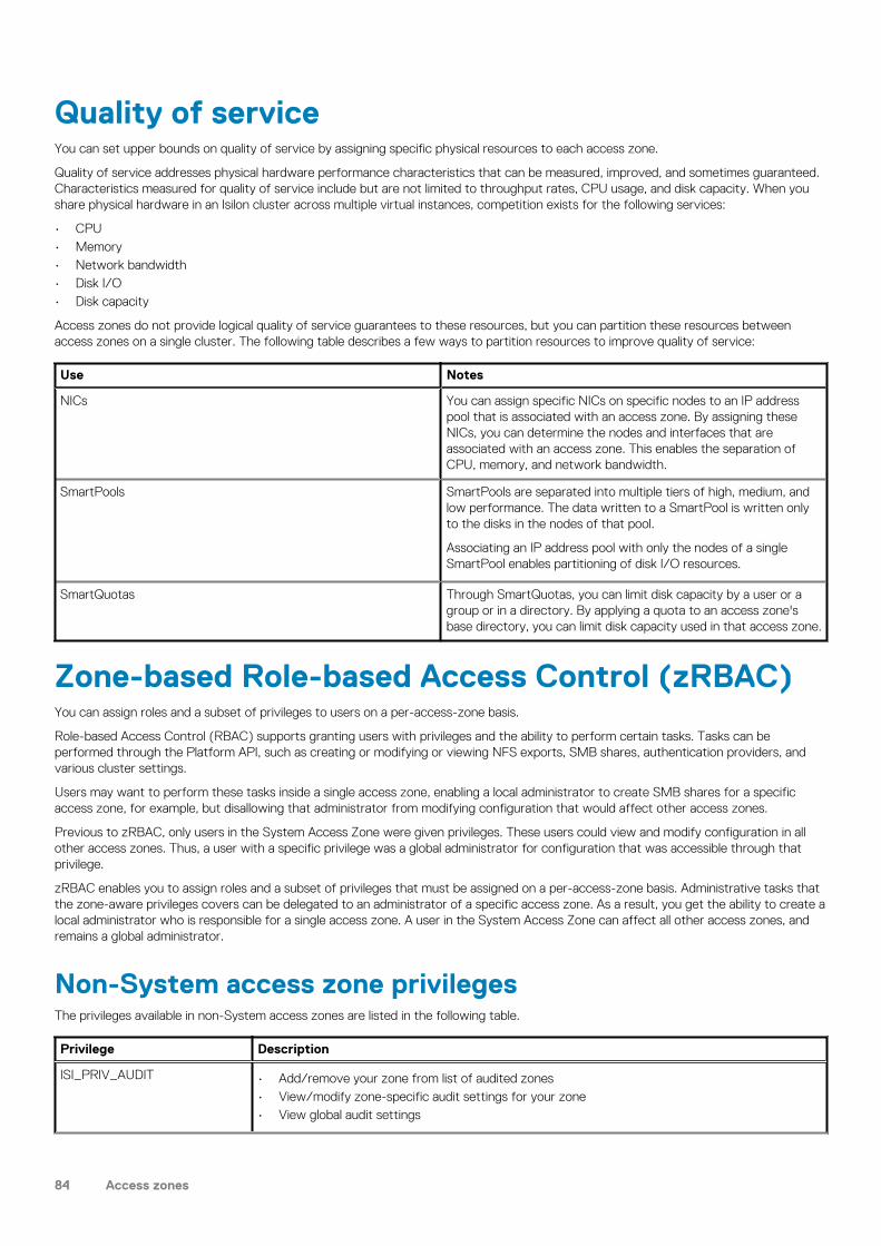
Quality of serviceYou can set upper bounds on quality of service by assigning specific physical resources to each access zone.
Quality of service addresses physical hardware performance characteristics that can be measured, improved, and sometimes guaranteed.Characteristics measured for quality of service include but are not limited to throughput rates, CPU usage, and disk capacity. When youshare physical hardware in an Isilon cluster across multiple virtual instances, competition exists for the following services:
• CPU• Memory• Network bandwidth• Disk I/O• Disk capacity
Access zones do not provide logical quality of service guarantees to these resources, but you can partition these resources betweenaccess zones on a single cluster. The following table describes a few ways to partition resources to improve quality of service:
Use Notes
NICs You can assign specific NICs on specific nodes to an IP addresspool that is associated with an access zone. By assigning theseNICs, you can determine the nodes and interfaces that areassociated with an access zone. This enables the separation ofCPU, memory, and network bandwidth.
SmartPools SmartPools are separated into multiple tiers of high, medium, andlow performance. The data written to a SmartPool is written onlyto the disks in the nodes of that pool.
Associating an IP address pool with only the nodes of a singleSmartPool enables partitioning of disk I/O resources.
SmartQuotas Through SmartQuotas, you can limit disk capacity by a user or agroup or in a directory. By applying a quota to an access zone'sbase directory, you can limit disk capacity used in that access zone.
Zone-based Role-based Access Control (zRBAC)You can assign roles and a subset of privileges to users on a per-access-zone basis.
Role-based Access Control (RBAC) supports granting users with privileges and the ability to perform certain tasks. Tasks can beperformed through the Platform API, such as creating or modifying or viewing NFS exports, SMB shares, authentication providers, andvarious cluster settings.
Users may want to perform these tasks inside a single access zone, enabling a local administrator to create SMB shares for a specificaccess zone, for example, but disallowing that administrator from modifying configuration that would affect other access zones.
Previous to zRBAC, only users in the System Access Zone were given privileges. These users could view and modify configuration in allother access zones. Thus, a user with a specific privilege was a global administrator for configuration that was accessible through thatprivilege.
zRBAC enables you to assign roles and a subset of privileges that must be assigned on a per-access-zone basis. Administrative tasks thatthe zone-aware privileges covers can be delegated to an administrator of a specific access zone. As a result, you get the ability to create alocal administrator who is responsible for a single access zone. A user in the System Access Zone can affect all other access zones, andremains a global administrator.
Non-System access zone privilegesThe privileges available in non-System access zones are listed in the following table.
Privilege Description
ISI_PRIV_AUDIT • Add/remove your zone from list of audited zones• View/modify zone-specific audit settings for your zone• View global audit settings
84 Access zones

Privilege Description
ISI_PRIV_AUTH • View/edit your access zone• Create/modify/view roles in your access zone• View/modify auth mapping settings for your zone• View global settings that are related to authentication
ISI_PRIV_FILE_FILTER Use all functionalities that are associated with this privilege, in your own zone.
ISI_PRIV_HDFS Use all functionalities that are associated with this privilege, in your own zone.
ISI_PRIV_NFS • View global NFS settings, but do not modify them.• Otherwise, use all functionality that is associated with this privilege, in your own zone.
ISI_PRIV_ROLE Use all functionalities that are associated with this privilege, but only in your own zone.
ISI_PRIV_SMB • View global SMB settings, but do not modify them.• Otherwise, use all functionalities that are associated with this privilege, in your own zone.
ISI_PRIV_SWIFT Use all functionalities that are associated with this privilege, in your own zone.
ISI_PRIV_VCENTER Configure VMware vCenter
ISI_PRIV_LOGIN_PAPI Access the WebUI from a non-System access zone
ISI_PRIV_BACKUP Bypass file permission checks and grant all read permissions.
ISI_PRIV_RESTORE Bypass file permission checks and grant all write permissions.
ISI_PRIV_NS_TRAVERSE Traverse and view directory metadata inside the zone base path.
ISI_PRIV_NS_IFS_ACCESS Access directories inside the zone base path through RAN
Built-in roles in non-System zonesIn the non-System access zone, two integrated roles are provided. The roles with their privileges are listed below:
Role Description Privileges
ZoneAdmin Allows administration of configurationaspects that are related to the currentaccess zone.
• ISI_PRIV_LOGIN_PAPI• ISI_PRIV_AUDIT• ISI_PRIV_FILE_FILTER• ISI_PRIV_HDFS• ISI_PRIV_NFS• ISI_PRIV_SMB• ISI_PRIV_SWIFT• ISI_PRIV_VCENTER• ISI_PRIV_NS_TRAVERSE• ISI_PRIV_NS_IFS_ACCESS
ZoneSecurityAdmin Allows administration of securityconfiguration aspects that are related tothe current access zone.
• ISI_PRIV_LOGIN_PAPI• ISI_PRIV_AUTH• ISI_PRIV_ROLE
NOTE: These roles do not have any default users who are automatically assigned to them.
Zone-specific authentication providersSome information about how authentication providers work with zRBAC.
Authentication providers are global objects in a OneFS cluster. However, as part of the zRBAC feature, an authentication provider isimplicitly associated with the access zone from which it was created, and has certain behaviors that are based on that association.
Access zones 85

• All access zones can view and use an authentication provider that is created from the System zone. However, only a request from theSystem access zone can modify or delete it.
• An authentication provider that is created from (or on behalf of) a non-System access zone can only be viewed or modified or deletedby that access zone and the System zone.
• A local authentication provider is implicitly created whenever an access zone is created, and is associated with that access zone.• A local authentication provider for a non-System access zone may no longer be used by another access zone. If you would like to
share a local authentication provider among access zones, then it must be the System zone's local provider.• The name of an authentication provider is still global. Therefore, authentication providers must have unique names. Thus, you cannot
create two LDAP providers named ldap5 in different access zones, for example.• The Kerberos provider can only be created from the System access zone.• Creating two distinct Active Directory (AD) providers to the same AD may require the use of the AD multi-instancing feature. To
assign a unique name to the AD provider, use --instance.
Managing access zonesYou can create access zones on an Isilon cluster, view and modify access zone settings, and delete access zones.
Create an access zoneYou can create an access zone to isolate data and restrict which users can access the data.
Run the isi zone zones create command.The following command creates an access zone named zone3 and sets the base directory to /ifs/hr/data:
isi zone zones create zone3 /ifs/hr/data
The following command creates an access zone named zone3, sets the base directory to /ifs/hr/data and creates the directory onthe cluster if it does not already exist:
isi zone zones create zone3 /ifs/hr/data --create-path
The following command creates an access zone named zone3, sets the base directory to /ifs/hr/data, and associates the accesszone with groupnet2:
isi zone zones create zone3 /ifs/hr/data --groupnet=groupnet2
Assign an overlapping base directoryYou can create overlapping base directories between access zones for cases where your workflows require shared data.
Run the isi zone zones create command.The following command creates an access zone named zone5 and sets the base directory to /ifs/hr/data even though the samebase directory was set for zone3:
isi zone zones create zone5 --path=/ifs/hr/data --force-overlap
Manage authentication providers in an access zoneYou modify an access zone to add and remove authentication providers. When you add an authentication provider, it must belong to thesame groupnet referenced by the access zone. When you remove an authentication provider from an access zone, the provider is notremoved from the system and remains available for future use.
The order in which authentication providers are added to access zone designates the order in which providers are searched duringauthentication and user lookup.
1. To add an authentication provider, run the isi zone zones modify command with the --add-auth-providers option.
You must specify the name of the authentication provider in the following format: <provider-type>:<provider-name>.
86 Access zones

The following command adds a file authentication provider named HR-Users to the zone3 access zone:
isi zone zones modify zone3 --add-auth-providers=file:hr-users2. To remove an authentication provider, run the isi zone zones modify command with the --remove-auth-providers
option.
You must specify the name of the authentication provider in the following format: <provider-type>:<provider-name>.
The following command removes the file authentication provider named HR-Users from the zone3 access zone:
isi zone zones modify zone3 --remove-auth-providers=file:hr-users
The following command removes all authentication providers from the zone3 access zone:
isi zone zones modify zone3 --clear-auth-providers
Associate an IP address pool with an access zoneYou can associate an IP address pool with an access zone to ensure that clients can connect to the access zone only through the range ofIP addresses assigned to the pool.
The IP address pool must belong to the same groupnet referenced by the access zone.
Run the isi network pools modify command.
Specify the pool ID you want to modify in the following format:
<groupnet_name>.<subnet_name>.<pool_name>
The following command associates zone3 with pool1 which is under groupnet1 and subnet1:
isi network pools modify groupnet1.subnet1.pool1 --access-zone=zone3
Modify an access zoneYou can modify the properties of any access zone except the name of the built-in System zone.
Run the isi zone zones modify command.The following command renames the zone3 access zone to zone5 and removes all current authentication providers from the access zone:
isi zone zones modify zone3 --name=zone5 --clear-auth-providers
Delete an access zoneYou can delete any access zone except the built-in System zone. When you delete an access zone, all associated authentication providersremain available to other access zones, but IP addresses are not reassigned to other access zones. SMB shares, NFS exports, and HDFSdata paths are deleted when you delete an access zone; however, the directories and data still exist, and you can map new shares,exports, or paths in another access zone.
Run the isi zone zones delete command.The following command deletes the zone3 access zone :
isi zone zones delete zone3
View a list of access zonesYou can view a list of all access zones on a cluster, or you can view details for a specific access zone.
1. To view a list of all access zones on the cluster, run the isi zone zones list command.
The system displays output similar to the following example:
Name Path------------------------
Access zones 87

System /ifszone3 /ifs/hr/benefitszone5 /ifs/marketing/collateral------------------------
2. To view the details of a specific access zone, run the isi zone zones view command and specify the zone name.The following command displays the setting details of zone5:
isi zone zones view zone5
The system displays output similar to the following example:
Name: zone5 Path: /ifs/marketing/collateral Groupnet: groupnet0 Map Untrusted: - Auth Providers: lsa-local-provider:zone5 NetBIOS Name: - User Mapping Rules: -Home Directory Umask: 0077 Skeleton Directory: /usr/share/skel Cache Entry Expiry: 4H Zone ID: 3
Create one or more access zonesYou can create one or more access zones.
1. Run the isi zone zones create command.The following commands create three access zones, named zone1, zone2, and zone3, sets the base directory to /ifs/access-zones/zone1,ifs/access-zones/zone2, and ifs/access-zones/zone3 and creates the directory on the cluster incase it does not exist:
isi zone zones create zone1 /ifs/access-zones/zone1 --create-pathisi zone zones create zone2 /ifs/access-zones/zone2 --create-pathisi zone zones create zone3 /ifs/access-zones/zone3 --create-path
2. Run the isi zone list command to view all the zones you have created:
isi zone listName Path------------------------------System /ifszone1 /ifs/access-zones/zone1zone2 /ifs/access-zones/zone2zone3 /ifs/access-zones/zone3------------------------------Total: 4
Create local users in an access zoneYou can create local users for different access zones.
1. Run the isi auth users create command.The following commands create three users in each access zone.
isi auth users create z1-user1 --enabled yes --password a --zone zone1isi auth users create z1-user2 --enabled yes --password a --zone zone1isi auth users create z1-user3 --enabled yes --password a --zone zone1isi auth users create z2-user1 --enabled yes --password a --zone zone2isi auth users create z2-user2 --enabled yes --password a --zone zone2 isi auth users create z2-user3 --enabled yes --password a --zone zone2isi auth users create z3-user1 --enabled yes --password a --zone zone3isi auth users create z3-user2 --enabled yes --password a --zone zone3isi auth users create z3-user3 --enabled yes --password a --zone zone3
88 Access zones

2. Run the isi auth users list command to view all users created in zone1:
isi auth users list --zone zone1Name--------Guestz1-user1z1-user2z1-user3rootnobody--------Total: 6
NOTE: To view users in zone2 and zone3, use the isi auth users list --zone zone2 and isi auth userslist --zone zone3 commands respectively.
Access files through the RESTful Access to Namespace(RAN) in non-System zonesYou can access data on the OneFS file system through RAN.
1. To access a file, you must make an HTTP call to /namespace/<path>.
curl -u user:password -k https://cluster.ip.addr:8080/namespace/ifs/data/file.txt2. When accessing files through a non-System zone, the path name must be within the base path of the access zone through which you
are accessing the data.For example, if IP address 1.2.3.4 is in zone2, which has a base path of /ifs/data/zone2, and then the following error is displayed:
NOTE: The user: password must be a valid user and password in access zone, zone2 in order to access RAN through
zone2.
# curl -u user:password -k 'https://1.2.3.4:8080/namespace/ifs/data/other-zone'
{"errors" : [
{"code" : "AEC_FORBIDDEN","message" : "Cannot access file/directory path outside base path of access zone"}]}
Access zones 89

AuthenticationThis section contains the following topics:
Topics:
• Authentication overview• Authentication provider features• Security Identifier (SID) history overview• Supported authentication providers• Active Directory• LDAP• NIS• Kerberos authentication• File provider• Local provider• Multi-factor Authentication (MFA)• Multi-instance active directory• LDAP public keys• Managing Active Directory providers• Managing LDAP providers• Managing NIS providers• Managing MIT Kerberos authentication• Managing file providers• Managing local users and groups• SSH Authentication and Configuration
Authentication overviewYou can manage authentication settings for your cluster, including authentication providers, Active Directory domains, LDAP, NIS, andKerberos authentication, file and local providers, multi-factor authentication, and more.
Authentication provider featuresYou can configure authentication providers for your environment.
Authentication providers support a mix of the features described in the following table.
Feature Description
Authentication All authentication providers support cleartext authentication. Youcan configure some providers to support NTLM or Kerberosauthentication also.
Users and groups OneFS provides the ability to manage users and groups directly onthe cluster.
Netgroups Specific to NFS, netgroups restrict access to NFS exports.
UNIX-centric user and group properties Login shell, home directory, UID, and GID. Missing information issupplemented by configuration templates or additionalauthentication providers.
Windows-centric user and group properties NetBIOS domain and SID. Missing information is supplemented byconfiguration templates.
6
90 Authentication

Security Identifier (SID) history overviewSID history preserves the membership and access rights of users and groups during an Active Directory domain migration.
Security identifier (SID) history preserves the membership and access rights of users and groups during an Active Directory domainmigration. When an object is moved to a new domain, the new domain generates a new SID with a unique prefix and records the previousSID information in an LDAP field. This process ensures that users and groups retain the same access rights and privileges in the newdomain that they had in the previous domain.
Note the following when working with historical SIDS.
• Use historical SIDs only to maintain historical file access and authentication privileges.• Do not use historical SIDs to add new users, groups, or roles.• Always use the current object SID as defined by the domain to modify a user or to add a user to any role or group.
Supported authentication providersYou can configure local and remote authentication providers to authenticate or deny user access to a cluster.
The following table compares features that are available with each of the authentication providers that OneFS supports. In the followingtable, an x indicates that a feature is fully supported by a provider; an asterisk (*) indicates that additional configuration or support fromanother provider is required.
Authenticationprovider
NTLM Kerberos User/groupmanagement
Netgroups UNIXproperties(RFC2307)
Windowsproperties
Active Directory x x * x
LDAP * x x x *
NIS x x
Local x x x x
File x x x
MIT Kerberos x * * *
Active DirectoryActive Directory is a Microsoft implementation of Lightweight Directory Access Protocol (LDAP), Kerberos, and DNS technologies thatcan store information about network resources. Active Directory can serve many functions, but the primary reason for joining the clusterto an Active Directory domain is to perform user and group authentication.
You can join the cluster to an Active Directory (AD) domain by specifying the fully qualified domain name, which can be resolved to anIPv4 or an IPv6 address, and a user name with join permission. When the cluster joins an AD domain, a single AD machine account iscreated. The machine account establishes a trust relationship with the domain and enables the cluster to authenticate and authorize usersin the Active Directory forest. By default, the machine account is named the same as the cluster. If the cluster name is more than 15characters long, the name is hashed and displayed after joining the domain.
OneFS supports NTLM and Microsoft Kerberos for authentication of Active Directory domain users. NTLM client credentials are obtainedfrom the login process and then presented in an encrypted challenge/response format to authenticate. Microsoft Kerberos clientcredentials are obtained from a key distribution center (KDC) and then presented when establishing server connections. For greatersecurity and performance, we recommend that you implement Kerberos, according to Microsoft guidelines, as the primary authenticationprotocol for Active Directory.
Each Active Directory provider must be associated with a groupnet. The groupnet is a top-level networking container that manageshostname resolution against DNS nameservers and contains subnets and IP address pools. The groupnet specifies which networkingproperties the Active Directory provider will use when communicating with external servers. The groupnet associated with the ActiveDirectory provider cannot be changed. Instead you must delete the Active Directory provider and create it again with the new groupnetassociation.
You can add an Active Directory provider to an access zone as an authentication method for clients connecting through the access zone.OneFS supports multiple instances of Active Directory on an Isilon cluster; however, you can assign only one Active Directory provider peraccess zone. The access zone and the Active Directory provider must reference the same groupnet. Configure multiple Active Directory
Authentication 91

instances only to grant access to multiple sets of mutually-untrusted domains. Otherwise, configure a single Active Directory instance if alldomains have a trust relationship. You can discontinue authentication through an Active Directory provider by removing the provider fromassociated access zones.
LDAPThe Lightweight Directory Access Protocol (LDAP) is a networking protocol that enables you to define, query, and modify directoryservices and resources.
OneFS can authenticate users and groups against an LDAP repository in order to grant them access to the cluster. OneFS supportsKerberos authentication for an LDAP provider.
The LDAP service supports the following features:
• Users, groups, and netgroups.• Configurable LDAP schemas. For example, the ldapsam schema allows NTLM authentication over the SMB protocol for users with
Windows-like attributes.• Simple bind authentication, with and without TLS.• Redundancy and load balancing across servers with identical directory data.• Multiple LDAP provider instances for accessing servers with different user data.• Encrypted passwords.• IPv4 and IPv6 server URIs.
Each LDAP provider must be associated with a groupnet. The groupnet is a top-level networking container that manages hostnameresolution against DNS nameservers and contains subnets and IP address pools. The groupnet specifies which networking properties theLDAP provider will use when communicating with external servers. The groupnet associated with the LDAP provider cannot be changed.Instead you must delete the LDAP provider and create it again with the new groupnet association.
You can add an LDAP provider to an access zone as an authentication method for clients connecting through the access zone. An accesszone may include at most one LDAP provider. The access zone and the LDAP provider must reference the same groupnet. You candiscontinue authentication through an LDAP provider by removing the provider from associated access zones.
NISThe Network Information Service (NIS) provides authentication and identity uniformity across local area networks. OneFS includes an NISauthentication provider that enables you to integrate the cluster with your NIS infrastructure.
NIS, designed by Sun Microsystems, can authenticate users and groups when they access the cluster. The NIS provider exposes thepasswd, group, and netgroup maps from an NIS server. Hostname lookups are also supported. You can specify multiple servers forredundancy and load balancing.
Each NIS provider must be associated with a groupnet. The groupnet is a top-level networking container that manages hostnameresolution against DNS nameservers and contains subnets and IP address pools. The groupnet specifies which networking properties theNIS provider will use when communicating with external servers. The groupnet associated with the NIS provider cannot be changed.Instead you must delete the NIS provider and create it again with the new groupnet association.
You can add an NIS provider to an access zone as an authentication method for clients connecting through the access zone. An accesszone may include at most one NIS provider. The access zone and the NIS provider must reference the same groupnet. You candiscontinue authentication through an NIS provider by removing the provider from associated access zones.
NOTE: NIS is different from NIS+, which OneFS does not support.
Kerberos authenticationKerberos is a network authentication provider that negotiates encryption tickets for securing a connection. OneFS supports MicrosoftKerberos and MIT Kerberos authentication providers on a cluster. If you configure an Active Directory provider, support for MicrosoftKerberos authentication is provided automatically. MIT Kerberos works independently of Active Directory.
For MIT Kerberos authentication, you define an administrative domain known as a realm. Within this realm, an authentication server hasthe authority to authenticate a user, host, or service; the server can resolve to either IPv4 or IPv6 addresses. You can optionally define aKerberos domain to allow additional domain extensions to be associated with a realm.
The authentication server in a Kerberos environment is called the Key Distribution Center (KDC) and distributes encrypted tickets. When auser authenticates with an MIT Kerberos provider within a realm, an encrypted ticket with the user's service principal name (SPN) iscreated and validated to securely pass the user's identification for the requested service.
92 Authentication

Each MIT Kerberos provider must be associated with a groupnet. The groupnet is a top-level networking container that manageshostname resolution against DNS nameservers and contains subnets and IP address pools. The groupnet specifies which networkingproperties the Kerberos provider will use when communicating with external servers. The groupnet associated with the Kerberos providercannot be changed. Instead you must delete the Kerberos provider and create it again with the new groupnet association.
You can add an MIT Kerberos provider to an access zone as an authentication method for clients connecting through the access zone. Anaccess zone may include at most one MIT Kerberos provider. The access zone and the Kerberos provider must reference the samegroupnet. You can discontinue authentication through an MIT Kerberos provider by removing the provider from associated access zones.
Keytabs and SPNs overviewA Key Distribution Center (KDC) is an authentication server that stores accounts and keytabs for users connecting to a network servicewithin a cluster. A keytab is a key table that stores keys to validate and encrypt Kerberos tickets.
One of the fields in a keytab entry is a service principal name (SPN). An SPN identifies a unique service instance within a cluster. EachSPN is associated with a specific key in the KDC. Users can use the SPN and its associated keys to obtain Kerberos tickets that enableaccess to various services on the cluster. A member of the SecurityAdmin role can create new keys for the SPNs and modify them later asnecessary. An SPN for a service typically appears as <service>/<fqdn>@<realm>.
NOTE: SPNs must match the SmartConnect zone name and the FQDN hostname of the cluster. If the SmartConnect
zone settings are changed, you must update the SPNs on the cluster to match the changes.
MIT Kerberos protocol supportMIT Kerberos supports certain standard network communication protocols such as HTTP, HDFS, and NFS. MIT Kerberos does notsupport SMB, SSH, and FTP protocols.
For the NFS protocol support, MIT Kerberos must be enabled for an export and also a Kerberos provider must be included within theaccess zone.
File providerA file provider enables you to supply an authoritative third-party source of user and group information to an Isilon cluster. A third-partysource is useful in UNIX and Linux environments that synchronize /etc/passwd, /etc/group, and etc/netgroup files acrossmultiple servers.
Standard BSD /etc/spwd.db and /etc/group database files serve as the file provider backing store on a cluster. You generate thespwd.db file by running the pwd_mkdb command in the OneFS command-line interface (CLI). You can script updates to the databasefiles.
On an Isilon cluster, a file provider hashes passwords with libcrypt. For the best security, we recommend that you use the ModularCrypt Format in the source /etc/passwd file to determine the hashing algorithm. OneFS supports the following algorithms for theModular Crypt Format:
• MD5• NT-Hash• SHA-256• SHA-512
For information about other available password formats, run the man 3 crypt command in the CLI to view the crypt man pages.
NOTE: The built-in System file provider includes services to list, manage, and authenticate against system accounts
such as root, admin, and nobody. We recommended that you do not modify the System file provider.
Local providerThe local provider provides authentication and lookup facilities for user accounts added by an administrator.
Local authentication is useful when Active Directory, LDAP, or NIS directory services are not configured or when a specific user orapplication needs access to the cluster. Local groups can include built-in groups and Active Directory groups as members.
In addition to configuring network-based authentication sources, you can manage local users and groups by configuring a local passwordpolicy for each node in the cluster. OneFS settings specify password complexity, password age and re-use, and password-attempt lockoutpolicies.
Authentication 93

Multi-factor Authentication (MFA)Multi-factor authentication (MFA) is a method of computer access control in which you are only granted access after successfullypresenting several separate pieces of evidence to an authentication mechanism. Typically, authentication uses at least two of the followingcategories: Knowledge (something you know); possession (something you have), and inherence (something you are).
MFA is a great way to increase the security of a cluster. Increasing the security of privileged account access (For example, administrators)to a cluster is the best way to prevent unauthorized access.
MFA enables the LSASS daemon to require and accept multiple forms of credentials other than a username or password combination forsome forms of authentication. There exist many ways to implement MFA with the most common being public or private keyauthentication.
The MFA feature adds PAPI support for SSH configuration using public keys that are stored in LDAP and Multi-Factor Authenticationsupport for SSH through the Duo security platform. Duo MFA supports the Duo App, SMS, and Voice.
The use of Duo requires an account with the Duo service. Duo provides a host, ikey, and skey to use for configuration (skey should betreated as a secure credential).
Duo MFA is on top of existing password and/or public key requirements. If the SSH configuration type is set to any or custom, Duo cannotbe configured. Only specific users or groups may be enabled to bypass MFA if specified on the Duo server. Duo enables the creation ofone time or date/time limited bypass keys for a specific user. Also, the bypass keys can be permanent.
Multi-instance active directoryIf you are a zone-local administrator, you can create your own AD instance, even if the AD instance for the same domain is already createdglobally or in another access zone.
Previously, only one connection to Active Directory was enabled, and the name of the Active Directory provider had to be the same as thename of the domain to which it was connecting. With the introduction of zone-local authentication providers, zone-local administratorscan create their own Active Directory provider, and be able to modify its parameters. To perform this action, you must do two things:
• Create a new provider instance name for this provider• Create a new machine account for this provider connection
An AD provider may have a name different than its domain name, using -instance. Then commands can use the instance name to find theparticular AD provider. Each access zone can have only one AD provider.
LDAP public keysYou can now use public SSH keys from LDAP rather than that of user's home directory on the OneFS cluster.
The LDAP create and modify commands support the --ssh-public-key-attribute option.
You can view your public key by adding --show-ssh-key.
Multiple keys may be specified in the LDAP configuration. The key that corresponds to the private key that is presented in the ssh sessionis used.
Nonetheless, you need a home directory on the cluster or you could get an error when you log in.
Managing Active Directory providersYou can view, configure, modify, and delete Active Directory providers. OneFS includes a Kerberos configuration file for Active Directory inaddition to the global Kerberos configuration file, both of which you can configure through the command-line interface. You candiscontinue authentication through an Active Directory provider by removing it from all access zones that are using it.
Configure an Active Directory providerYou can configure one or more Active Directory providers, each of which must be joined to a separate Active Directory domain. By default,when you configure an Active Directory provider, it is automatically added to the System access zone.
NOTE: Consider the following information when you configure an Active Directory (AD) provider:
94 Authentication

• When you join Active Directory from OneFS, cluster time is updated from the Active Directory server, as long as an
NTP server has not been configured for the cluster.
• The Active Directory provider must be associated with a groupnet.
• The Active Directory domain can be resolved to an IPv4 or an IPv6 address.
Run the isi auth ads create command to create an Active Directory provider by specifying the domain name of the ActiveDirectory server and the name of an AD user that has permission to join machines to the AD domain.The following command specifies adserver.company.com as the fully-qualified domain name of the Active Directory server to be created inthe system, specifies "administrator" as the AD user that has permission to join the cluster to the AD domain, and associates the providerwith groupnet3:
isi auth ads create --name=adserver.company.com \ --user=administrator --groupnet=groupnet3
Modify an Active Directory providerYou can modify the advanced settings for an Active Directory provider.
Run the following command to modify an Active Directory provider, where <provider-name> is a placeholder for the name of the providerthat you want to modify.
isi auth ads modify <provider-name>
Delete an Active Directory providerWhen you delete an Active Directory provider, you disconnect the cluster from the Active Directory domain that is associated with theprovider, disrupting service for users who are accessing it. After you leave an Active Directory domain, users can no longer access thedomain from the cluster.
Run the following command to Delete an Active Directory provider, where <name> is a placeholder for the Active Directory name that youwant to delete.
isi auth ads delete <name>
Managing LDAP providersYou can view, configure, modify, and delete LDAP providers. You can discontinue authentication through an LDAP provider by removing itfrom all access zones that are using it.
Configure an LDAP providerBy default, when you configure an LDAP provider, it is automatically added to the System access zone.
Run the isi auth ldap create command to create an LDAP provider.The following command creates an LDAP provider called test-ldap and associates it with groupnet3. The command also sets a basedistinguished name, which specifies the root of the tree in which to search for identities, and specifies ldap://2001:DB8:170:7cff::c001 asthe server URI:
isi auth ldap create test-ldap \ --base-dn="dc=test-ldap,dc=example,dc=com" \ --server-uris="ldap://[2001:DB8:170:7cff::c001]" \ --groupnet=groupnet3
NOTE: The base distinguished name is specified as a sequence of relative distinguished name values, separated by
commas. Specify a base distinguished name if the LDAP server allows anonymous queries.
The following command creates an LDAP provider called test-ldap and associates it with groupnet3. It also specifies a bind distinguishedname and bind password, which are used to join the LDAP server, and specifies ldap://test-ldap.example.com as the server URI:
isi auth ldap create test-ldap \ --base-dn="dc=test-ldap,dc=example,dc=com" \
Authentication 95

--bind-dn="cn=test,ou=users,dc=test-ldap,dc=example,dc=com" \ --bind-password="mypasswd" \ --server-uris="ldap://test-ldap.example.com" \ --groupnet=groupnet3
NOTE: The bind distinguished name is specified as a sequence of relative distinguished name values, separated by
commas, and must have the proper permissions to join the LDAP server to the cluster. Specify a bind distinguished
name if the LDAP server does not allow anonymous queries.
Modify an LDAP providerYou can modify any setting for an LDAP provider except its name. You must specify at least one server for the provider to be enabled.
Run the following command to modify an LDAP provider, where <provider-name> is a placeholder for the name of the provider that youwant to modify:
isi auth ldap modify <provider-name>
Delete an LDAP providerWhen you delete an LDAP provider, it is removed from all access zones. As an alternative, you can stop using an LDAP provider byremoving it from each access zone that contains it so that the provider remains available for future use.
For information about the parameters and options that are available for this procedure, run the isi auth ldap delete --helpcommand.
Run the following command to delete an LDAP provider, where <name> is a placeholder for the name of the LDAP provider that you wantto delete.
isi auth ldap delete <name>
Managing NIS providersYou can view, configure, and modify NIS providers or delete providers that are no longer needed. You can discontinue authenticationthrough an NIS provider by removing it from all access zones that are using it.
Configure an NIS providerYou can configure multiple NIS providers, each with its own settings, and add them to one or more access zones.
Configure an NIS provider by running the isi auth nis create command.The following example creates an NIS provider called nistest that is associated with groupnet3, specifies nistest.company.com as the NISserver and company.com as the domain:
isi auth nis create nistest --groupnet=groupnet3\--servers="nistest.example.com" --nis-domain="example.com"
Modify an NIS providerYou can modify any setting for an NIS provider except its name. You must specify at least one server for the provider to be enabled.
Run the following command to modify an NIS provider, where <provider-name> is a placeholder for provider that you want to modify.
isi auth nis modify <provider-name>
96 Authentication

Delete an NIS providerWhen you delete an NIS provider, it is removed from all access zones. As an alternative, you can stop using an NIS provider by removing itfrom each access zone that contains it, so that the provider remains available for future use.
Run the following command to delete an NIS provider, where <name> is a placeholder for the name of the NIS provider that you want todelete.
isi auth nis delete <name>
Managing MIT Kerberos authenticationYou can configure an MIT Kerberos provider for authentication without Active Directory. Configuring an MIT Kerberos provider involvescreating an MIT Kerberos realm, creating a provider, and joining a predefined realm. Optionally, you can configure an MIT Kerberos domainfor the provider. You can also update the encryption keys if there are any configuration changes to the Kerberos provider. You can includethe provider in one or more access zones.
Managing MIT Kerberos realmsAn MIT Kerberos realm is an administrative domain that defines the boundaries within which an authentication server has the authority toauthenticate a user or service. You can create, view, edit, or delete a realm. As a best practice, specify a realm name using uppercasecharacters.
Create an MIT Kerberos realmYou can create an MIT Kerberos realm by defining a Key Distribution Center (KDC) and an administrative server.
You must be a member of a role that has ISI_PRIV_AUTH privileges to create an MIT Kerberos realm.
Run the isi auth krb5 realm create command to create an MIT Kerberos realm.The following command creates an MIT Kerberos realm called TEST.COMPANY.COM, specifies admin.test.company.com as theadministrative server, and specifies keys.test.company.com as a key distribution center:
isi auth krb5 realm create --realm=TEST.COMPANY.COM \ --kdc=keys.test.company.com --admin-server=admin.test.company.com
The realm name is case-sensitive and must be specified in uppercase letters. The administrative server and key distribution center can bespecified as an IPv4 address, an IPv6 address, or a hostname.
Modify an MIT Kerberos realmYou can modify an MIT Kerberos realm by modifying the Key Distribution Center (KDC), the domain (optional), and the administrativeserver settings for that realm.
You must be a member of a role that has ISI_PRIV_AUTH privileges to delete an MIT Kerberos provider.
Run the isi auth krb5 realm modify command to modify an MIT Kerberos realm.The following command modifies the MIT Kerberos realm called TEST.COMPANY.COM by adding a KDC specified as an IPv6 address:
isi auth krb5 realm modify --realm=TEST.COMPANY.COM \ --kdc=2001:DB8:170:7cff::c001
The realm name is case-sensitive and must be specified in uppercase letters. The key distribution center can be specified as an IPv4address, an IPv6 address, or a host name.
View an MIT Kerberos realmYou can view details related to the name, Key Distribution Centers (KDCs), and the administrative server associated with an MIT Kerberosrealm.
1. To view a list of all Kerberos realms configured on the cluster, run the isi auth krb5 realm list command.
Authentication 97

The system displays output similar to the following example:
Realm---------------TEST.COMPANY.COMENGKERB.COMPANY.COMOPSKERB.COMPANY.COM---------------Total: 3
2. To view the setting details for a specific Kerberos realm, run the isi auth krb5 realm view command followed by the realmname.
The specified realm name is case-sensitive.
The following command displays setting details for the realm called TEST.COMPANY.COM:
isi auth krb realm view TEST.COMPANY.COM
The systems displays output similar to the following example:
Realm: TEST.COMPANY.COMIs Default Realm: Yes KDC: 2001:DB8:170:7cff::c001, keys.test.company.com Admin Server: admin.test.company.com
NOTE: The KDC and the admin server can be specified as an IPv4 or IPv6 address, or a hostname.
Delete an MIT Kerberos realmYou can delete one or more MIT Kerberos realms and all the associated MIT Kerberos domains.
Kerberos realms are referenced by Kerberos providers. Before you can delete a realm for which you have created a provider, you mustfirst delete that provider.
You must be a member of a role that has ISI_PRIV_AUTH privileges to delete an MIT Kerberos realm.
Run the isi auth krb5 realm delete command to delete an MIT Kerberos realm.
For example, run the following command to delete a realm:
isi auth krb5 realm delete <realm>
Managing MIT Kerberos providersYou can create view, delete, or modify an MIT Kerberos provider. You can also configure the Kerberos provider settings.
Creating an MIT Kerberos providerYou can create an MIT Kerberos provider by obtaining the credentials for accessing a cluster through the Key Distribution Center (KDC)of the Kerberos realm. This process is also known as joining a realm. Thus when you create a Kerberos provider you also join a realm thathas been previously defined.
Depending on how OneFS manages your Kerberos environment, you can create a Kerberos provider through one of the followingmethods:
• Accessing the Kerberos administration server and creating keys for services on the OneFS cluster.• Manually transferring the Kerberos key information in the form of keytabs.
Create an MIT Kerberos provider and join a realm with administrator credentialsYou can create an MIT Kerberos provider and join an MIT Kerberos realm using the credentials authorized to access the Kerberosadministration server. You can then create keys for the various services on the cluster. This is the recommended method for creating aKerberos provider and joining a Kerberos realm.
You must be a member of a role that has ISI_PRIV_AUTH privileges to access the Kerberos administration server.
98 Authentication

Run the isi auth krb5 create command to create a Kerberos provider and join a Kerberos realm; , where <realm> is the name ofthe Kerberos realm which already exists or is created if it does not exist:
The realm name is case-sensitive and must be specified in uppercase letters.
In the following example command, the Kerberos realm TEST.COMPANY.COM is created and joined to the provider, which is associatedwith groupnet3. The command also specifies admin.test.company.com as the administrative server and keys.test.company.com as theKDC, and specifies a username and password that are authorized to access to the administration server:
isi auth krb5 create --realm=TEST.COMPANY.COM \--user=administrator --password=secretcode \--kdc=keys.test.company.com \--admin-server=admin.test.company.com \--groupnet=groupnet3
NOTE: The KDC and the admin server can be specified as an IPv4 or IPv6 address, or a hostname.
Create an MIT Kerberos provider and join a realm with a keytab fileYou can create an MIT Kerberos provider and join an MIT Kerberos realm through a keytab file. Follow this method only if your Kerberosenvironment is managed by manually transferring the Kerberos key information through the keytab files.
Make sure that the following prerequisites are met:
• The Kerberos realm must already exist on the cluster• A keytab file must exist on the cluster.• You must be a member of a role that has ISI_PRIV_AUTH privileges to access the Kerberos administration server.
Run the isi auth krb5 create command.The following command creates a Kerberos provider that is associated with groupnet3, joins the Kerberos realm called cluster-name.company.com and specifies a keytab file located at /tmp/krb5.keytab:
isi auth krb5 create cluster-name.company.com \--keytab-file=/tmp/krb5.keytab --groupnet=groupnet3
View an MIT Kerberos providerYou can view the properties of an MIT Kerberos provider after creating it.
Run the following command to view the properties of a Kerberos provider:
isi auth krb5 view <provider-name>
List the MIT Kerberos providersYou can list one or more MIT Kerberos providers and display the list in a specific format. You can also specify a limit for the number ofproviders to be listed.
Run the isi auth krb5 list command to list one or more Kerberos providers.
For example, run the following command to list the first five Kerberos providers in a tabular format without any headers or footers:
isi auth krb5 list -l 5 --format table --no-header --no-footer
Delete an MIT Kerberos providerYou can delete an MIT Kerberos provider and remove it from all the referenced access zones. When you delete a provider, you also leavean MIT Kerberos realm.
You must be a member of a role that has ISI_PRIV_AUTH privileges to delete a Kerberos provider.
Run the isi auth krb5 delete command as follows to delete a Kerberos provider.
isi auth krb5 delete <provider-name>
Authentication 99

Configure MIT Kerberos provider settingsYou can configure the settings of a Kerberos provider to allow the DNS records to locate the Key Distribution Center (KDC), Kerberosrealms, and the authentication servers associated with a Kerberos realm. These settings are global to all Kerberos users across all nodes,services, and zones. Some settings are applicable only to client-side Kerberos and are independent of the Kerberos provider.
You must be a member of a role that has ISI_PRIV_AUTH privileges to view or modify the settings of a Kerberos provider.
1. Run the isi auth settings krb5 command with the view or modify subcommand.
2. Specify the settings to modify.
Managing MIT Kerberos domainsYou can optionally define MIT Kerberos domains to allow additional domain extensions to be associated with an MIT Kerberos realm. Youcan always specify a default domain for a realm.
You can create, modify, delete, and view an MIT Kerberos domain. A Kerberos domain name is a DNS suffix that you specify typically usinglowercase characters.
Add an MIT Kerberos domain to a realmYou can optionally add an MIT Kerberos domain to an MIT Kerberos realm to enable additional Kerberos domain extensions to beassociated with a Kerberos realm.
You must be a member of a role that has ISI_PRIV_AUTH privileges to associate a Kerberos domain with a Kerberos realm.
Add a Kerberos domain by running the isi auth krb5 domain create command.
For example, run the following command to add a Kerberos domain to a Kerberos realm:
isi auth krb5 domain create <domain>
Modify an MIT Kerberos domainYou can modify an MIT Kerberos domain by modifying the realm settings.
You must be a member of a role that has ISI_PRIV_AUTH privileges to modify an MIT Kerberos domain.
Run the isi auth krb5 domain modify command to modify a Kerberos domain.
For example, run the following command to modify a Kerberos domain by specifying an alternate Kerberos realm:
isi auth krb5 domain modify <domain> --realm <realm>
View an MIT Kerberos domain mappingYou can view the properties of an MIT Kerberos domain mapping.
Run the isi auth krb5 domain view command with a value specified for the <domain> variable to view the properties of aKerberos domain mapping:
isi auth krb5 domain view <domain>
List MIT Kerberos domainsYou can list one or more MIT Kerberos domains and display the list in a tabular, JSON, CSV, or list format. You can also specify a limit forthe number of domains to be listed.
Run the isi auth krb5 domain list command to list one or more MIT Kerberos domains.
For example, run the following command to list the first ten MIT Kerberos domains in a tabular format without any headers or footers:
isi auth krb5 domain list -l=10 --format=table --no-header --no-footer
100 Authentication

Delete an MIT Kerberos domain mappingYou can delete one or more MIT Kerberos domain mappings.
You must be a member of a role that has ISI_PRIV_AUTH privileges to delete an MIT Kerberos domain mapping.
Run the isi auth krb5 domain delete command to delete an MIT Kerberos domain mapping.
For example, run the following command to delete a domain mapping:
isi auth krb5 domain delete <domain>
Managing SPNs and keysA service principal name (SPN) is the name referenced by a client to identify an instance of a service on a cluster. An MIT Kerberosprovider authenticates services on a cluster through SPNs.
You can perform the following operations on SPNs and their associated keys:
• Update the SPNs if there are any changes to the SmartConnect zone settings that are based on those SPNs• List the registered SPNs to compare them against a list of discovered SPNs• Update keys associated with the SPNs either manually or automatically• Import keys from a keytab table• Delete specific key versions or delete all the keys associated with an SPN
View SPNs and keysYou can view the service principal names (SPNs) and their associated keys that are registered for an MIT Kerberos provider. Clientsobtain Kerberos tickets and access services on clusters through SPNs and their associated keys.
You must be a member of a role that has ISI_PRIV_AUTH privileges to view SPNs and keys.
Run the isi auth krb5 spn list command to list one or more SPNs and their associated keys and the Key version numbers(Kvnos).
For example, run the following command to list the first five SPNs for an MIT Kerberos provider in a tabular format without any headers orfooters:
isi auth krb5 list <provider-name> -l 5 --format table --no-header --no-footer <spn-list>
Delete keysYou can delete specific key versions or all the keys associated with a service principal name (SPN).
You must be a member of a role that has ISI_PRIV_AUTH privileges to delete keys.
After creating new keys due to security reasons or to match configuration changes, follow this procedure to delete older version of thekeys so that the keytab table is not populated with redundant keys.
Run the isi auth krb5 spn delete command to delete all keys for a specified SPN or a specific version of a key.For example, run the following command to delete all the keys associated with an SPN for an MIT Kerberos provider:
isi auth krb5 spn delete <provider-name> <spn> --all
The <provider-name> is the name of the MIT Kerberos provider. You can delete a specific version of the key by specifying a key versionnumber value for the kvno argument and including that value in the command syntax.
Manually add or update a key for an SPNYou can manually add or update keys for a service principal name (SPN). This process creates a new key for the specified SPN.
You must be a member of a role that has ISI_PRIV_AUTH privileges to add or update a key for an SPN.
Run the isi auth krb5 spn create command to add or update keys for an SPN.
Authentication 101

For example, run the following command to add or update a key for an SPN by specifying the <provider-name>, <user>, and <spn>positional arguments:
isi auth krb5 spn create <provider-name> <user> <spn>
Automatically update an SPNYou can automatically update or add a service principal name (SPN) if it is registered with an MIT Kerberos provider but does not appearin the list of discovered SPNs.
You must be a member of a role that has ISI_PRIV_AUTH privileges to automatically update an SPN.
1. Run the isi auth krb5 spn check command to compare the list of registered SPNs against the list of discovered SPNs.
Proceed to the next step if the comparison does not show similar results.
2. Run the isi auth krb5 spn fix command to fix the missing SPNs.
For example, run the following command to add missing SPNs for an MIT Kerberos service provider:
isi auth krb5 spn fix <provider-name> <user>
You can optionally specify a password for <user> which is the placeholder for a user who has the permission to join clients to the givendomain.
Import a keytab fileAn MIT Kerberos provider joined through a legacy keytab file might not have the ability to manage keys through the Kerberos admincredentials. In such a case, import a new keytab file and then add the keytab file keys to the provider.
Make sure that the following pre-requisites are met before you import a keytab file:
• You must create and copy a keytab file to a node on the cluster where you will perform this procedure.• You must be a member of a role that has ISI_PRIV_AUTH privileges to import a keytab file.
Import the keys of a keytab file by running the isi auth krb5 spn import command.
For example, run the following command to import the keys of the <keytab-file> to the provider referenced as <provider-name>:
isi auth krb5 spn import <provider-name> <keytab-file>
Managing file providersYou can configure one or more file providers, each with its own combination of replacement files, for each access zone. Passworddatabase files, which are also called user database files, must be in binary format.
Each file provider pulls directly from up to three replacement database files: a group file that has the same format as /etc/group; anetgroups file; and a binary password file, spwd.db, which provides fast access to the data in a file that has the /etc/master.passwd format. You must copy the replacement files to the cluster and reference them by their directory path.
NOTE: If the replacement files are located outside the /ifs directory tree, you must distribute them manually to every
node in the cluster. Changes that are made to the system provider's files are automatically distributed across the
cluster.
Configure a file providerYou can specify replacement files for any combination of users, groups, and netgroups.
Run the following command to configure a file provider, where <name> is your name for the file provider.
isi auth file create <name>
102 Authentication

Generate a password filePassword database files, which are also called user database files, must be in binary format.
This procedure must be performed through the command-line interface (CLI). For command-usage guidelines, run the man pwd_mkdbcommand.
1. Establish an SSH connection to any node in the cluster.2. Run the pwd_mkdb <file> command, where <file> is the location of the source password file.
NOTE: By default, the binary password file, spwd.db, is created in the /etc directory. You can override the location
to store the spwd.db file by specifying the -d option with a different target directory.
The following command generates an spwd.db file in the /etc directory from a password file that is located at /ifs/test.passwd:
pwd_mkdb /ifs/test.passwd
The following command generates an spwd.db file in the /ifs directory from a password file that is located at /ifs/test.passwd:
pwd_mkdb -d /ifs /ifs/test.passwd
Modify a file providerYou can modify any setting for a file provider, including its name.
NOTE: Although you can rename a file provider, there are two caveats: you can rename a file provider through only the
web administration interface and you cannot rename the System file provider.
Run the following command to modify a file provider, where <provider-name> is a placeholder for the name that you supplied for theprovider.
isi auth file modify <provider-name>
Delete a file providerTo stop using a file provider, you can clear all of its replacement file settings or you can permanently delete the provider.
NOTE: You cannot delete the System file provider.
Run the following command to delete a file provider, where <name> is a placeholder for the name of the provider that you want to delete.
isi auth file delete <name>
Password file formatThe file provider uses a binary password database file, spwd.db. You can generate a binary password file from a master.passwd-formatted file by running the pwd_mkdb command.
The master.passwd file contains ten colon-separated fields, as shown in the following example:
admin:*:10:10::0:0:Web UI Administrator:/ifs/home/admin:/bin/zsh
The fields are defined below in the order in which they appear in the file.
NOTE: UNIX systems often define the passwd format as a subset of these fields, omitting the Class, Change, and Expiry
fields. To convert a file from passwd to master.passwd format, add :0:0: between the GID field and the Gecos field.
Username The user name. This field is case-sensitive. OneFS does not limit the length; many applications truncate the nameto 16 characters, however.
Authentication 103

Password The user’s encrypted password. If authentication is not required for the user, you can substitute an asterisk (*)for a password. The asterisk character is guaranteed to not match any password.
UID The UNIX user identifier. This value must be a number in the range 0-4294967294 that is not reserved oralready assigned to a user. Compatibility issues occur if this value conflicts with an existing account's UID.
GID The group identifier of the user’s primary group. All users are a member of at least one group, which is used foraccess checks and can also be used when creating files.
Class This field is not supported by OneFS and should be left empty.
Change OneFS does not support changing the passwords of users in the file provider. This field is ignored.
Expiry OneFS does not support the expiration of user accounts in the file provider. This field is ignored.
Gecos This field can store a variety of information but is usually used to store the user’s full name.
Home The absolute path to the user’s home directory, beginning at /ifs.
Shell The absolute path to the user’s shell. If this field is set to /sbin/nologin, the user is denied command-lineaccess.
Group file formatThe file provider uses a group file in the format of the /etc/group file that exists on most UNIX systems.
The group file consists of one or more lines containing four colon-separated fields, as shown in the following example:
admin:*:10:root,admin
The fields are defined below in the order in which they appear in the file.
Group name The name of the group. This field is case-sensitive. Although OneFS does not limit the length of the group name,many applications truncate the name to 16 characters.
Password This field is not supported by OneFS and should contain an asterisk (*).
GID The UNIX group identifier. Valid values are any number in the range 0-4294967294 that is not reserved oralready assigned to a group. Compatibility issues occur if this value conflicts with an existing group's GID.
Group members A comma-delimited list of user names.
Netgroup file formatA netgroup file consists of one or more netgroups, each of which can contain members. Hosts, users, or domains, which are members of anetgroup, are specified in a member triple. A netgroup can also contain another netgroup.
Each entry in a netgroup file consists of the netgroup name, followed by a space-delimited set of member triples and nested netgroupnames. If you specify a nested netgroup, it must be defined on a separate line in the file.
A member triple takes the following form:
(<host>, <user>, <domain>)
Where <host> is a placeholder for a machine name, <user> is a placeholder for a user name, and <domain> is a placeholder for a domainname. Any combination is valid except an empty triple: (,,).
The following sample file contains two netgroups. The rootgrp netgroup contains four hosts: two hosts are defined in member triples andtwo hosts are contained in the nested othergrp netgroup, which is defined on the second line.
rootgrp (myserver, root, somedomain.com) (otherserver, root, somedomain.com) othergrpothergrp (other-win,, somedomain.com) (other-linux,, somedomain.com)
NOTE: A new line signifies a new netgroup. You can continue a long netgroup entry to the next line by typing a backslash
character (\) in the right-most position of the first line.
104 Authentication

Managing local users and groupsWhen you create an access zone, each zone includes a local provider that allows you to create and manage local users and groups.Although you can view the users and groups of any authentication provider, you can create, modify, and delete users and groups in thelocal provider only.
View a list of users and groups by providerYou can view users and groups by a provider type.
1. Run the following command to view a list of users and groups for a specified provider, where <provider-type> is a placeholder for yourprovider-type string and <provider-name> is a placeholder for the name that you assigned the specific provider:
isi auth users list --provider="<provider-type>:<provider-name>"
2. To list users and groups for an LDAP provider type that is named Unix LDAP, run a command similar to the following example:
isi auth users list --provider="lsa-ldap-provider:Unix LDAP"
Create a local userEach access zone includes a local provider that allows you to create and manage local users and groups. When creating a local useraccount, you can configure its name password, home directory, UNIX user identifier (UID), UNIX login shell, and group memberships.
Run the following command to create a local user, where <name> is your name for the user, <provider-name> specifies the provider forthis user, and <string> is the password for this user.
isi auth users create <name> --provider="local:<provider-name>" \ --password="<string>"
NOTE: A user account is disabled if no password is specified. If you do not create a password when you create the user
account, you can add a password later by running the isi auth users modify command, specifying the appropriate
user by username, UID, or SID.
Create a local groupIn the local provider of an access zone, you can create groups and assign members to them.
Run the following command to create a local group, where <name> and <provider-name> are values that you provide to define the group.
isi auth groups create <name> --provider "local:<provider-name>"
Naming rules for local users and groupsLocal user and group names must follow naming rules in order to ensure proper authentication and access to the cluster.
You must adhere to the following naming rules when creating and modifying local users and groups:
• The maximum name length is 104 characters. It is recommended that names do not exceed 64 characters.• Names cannot contain the following invalid characters:
" / \ [ ] : ; | = , + * ? < >• Names can contain any special character that is not in the list of invalid characters. It is recommend that names do not contain spaces.• Names are not case sensitive.
Configure or modify a local password policyYou can configure and modify a local password policy for a local provider.
This procedure must be performed through the command-line interface (CLI).
Authentication 105

NOTE: Separate password policies are configured for each access zone. Each access zone in the cluster contains a
separate instance of the local provider, which allows each access zone to have its own list of local users who can
authenticate. Password complexity is configured for each local provider, not for each user.
1. Establish an SSH connection to any node in the cluster.2. Optional: Run the following command to view the current password settings:
isi auth local view system
3. Run the isi auth local modify command, choosing from the parameters described in Local password policy default settings.
The --password-complexity parameter must be specified for each setting.
isi auth local modify system --password-complexity=lowercase \ --password-complexity=uppercase -–password-complexity=numeric \ --password-complexity=symbol
The following command configures a local password policy for a local provider:
isi auth local modify <provider-name> \ --min-password-length=20 \ --lockout-duration=20m \ --lockout-window=5m \ --lockout-threshold=5 \ --add-password-complexity=uppercase \ --add-password-complexity=numeric
Local password policy settingsYou can configure local password policy settings and specify the default for each setting through the isi auth local modifycommand. Password complexity increases the number of possible passwords that an attacker must check before the correct password isguessed.
Setting Description Comments
min-password-length Minimum password length incharacters.
Long passwords are best. The minimum lengthshould not be so long that users have a difficult timeentering or remembering the password.
password-complexity A list of cases that a new passwordmust contain. By default, the list isempty.
You can specify as many as four cases. The followingcases are valid:
• uppercase• lowercase• numeric• symbol (excluding # and @)
min-password-age The minimum password age. You canset this value using characters forunits; for example, 4W for 4 weeks, 2dfor 2 Days.
A minimum password age ensures that a user cannotenter a temporary password and then immediatelychange it to the previous password. Attempts tocheck or set a password before the time expires aredenied.
max-password-age The maximum password age. You canset this value using characters forunits; for example, 4W for 4 weeks, 2dfor 2 Days.
Attempts to login after a password expires forces apassword change. If a password change dialogcannot be presented, the user is not allowed to login.
password-history-length The number of historical passwords tokeep. New passwords are checkedagainst this list and rejected if thepassword is already present. The maxhistory length is 24.
To avoid recycling of passwords, you can specify thenumber of previous passwords to remember. If anew password matches a remembered previouspassword, it is rejected.
106 Authentication

Setting Description Comments
lockout-duration The length of time in seconds that anaccount is locked after a configurablenumber of bad passwords are entered.
After an account is locked, it is unavailable from allsources until it is unlocked. OneFS provides twoconfigurable options to avoid administratorinteraction for every locked account:
• Specify how much time must elapse before theaccount is unlocked.
• Automatically reset the incorrect-passwordcounter after a specified time, in seconds.
lockout-threshold The number of incorrect passwordattempts before an account is locked.A value of zero disables accountlockout.
After an account is locked, it is unavailable from allsources until it is unlocked.
lockout-window The time that elapses before theincorrect password attempts count isreset.
If the configured number of incorrect passwordattempts is reached, the account is locked andlockout-duration determines the length of time thatthe account is locked. A value of zero disables thewindow.
Modify a local userYou can modify any setting for a local user account except the user name.
Run the following command to modify a local group, where <name> or <gid> or <sid> are placeholders for the user identifiers and<provider-name> is a placeholder for the name of the local provider associated with the user:
isi auth users modify (<name> or --gid <gid> or --sid <sid>) \ --provider "local:<provider-name>"
Modify a local groupYou can add or remove members from a local group.
Run the following command to modify a local group, where <name> or <gid> or <sid> are placeholders for the group identifiers and<provider-name> is a placeholder for the name of the local provider associated with the group:
isi auth groups modify (<name> or --gid <gid> or --sid <sid>) \ --provider "local:<provider-name>"
Delete a local userA deleted user can no longer access the cluster through the command-line interface, web administration interface, or file access protocol.When you delete a local user account, its home directory remains in place.
Run the following command to delete a local user, where <uid> and <sid> are placeholders for the UID and SID of the user that you wantto delete, and <provider-name> is a placeholder for the local provider associated with the user.
isi auth users delete <name> --uid <uid> --sid <sid> \ --provider "local:<provider-name>"
Delete a local groupYou can delete a local group even if members are assigned to it. Deleting a group does not affect the members of that group.
Run the following command to delete a local group, where <group> is a placeholder for the name of the group that you want to delete:
isi auth groups delete <group>
Authentication 107

NOTE: You can run the command with <gid> or <sid> instead of <group>.
SSH Authentication and ConfigurationMulti-Factor Authentication (MFA) adds PAPI support for SSH configuration using public keys stored in LDAP and Multi-FactorAuthentication support for SSH via the Duo security platform.
Pre-requisites for Multi-factor Authentication (MFA)In order to successfully authenticate through the MFA feature, the following must be true regarding the target user:
• The user identity on cluster must belong to a role that enables SSH access.• The auth-settings-template SSH setting must be set to anything but any or custom.• If the user-auth-method SSH setting is set to publickey, all users that need SSH access must have a valid public key value for
sshPublicKey in their LDAP entry.• If the user-auth-method SSH setting is set to password, all users that need SSH access must have a valid password value for
userPassword in their LDAP entry.
Also, the host, ikey, and skey must be set. You must set the enabled option in the isi auth duo command.
NOTE: This feature will only work as expected if the previous conditions are met. If any of the conditions above are not
met, you could risk locking yourself out of your node.
SSH configuration using passwordYou can provide CLI support for SSH configuration using a password.
1. To provide support for SSH configuration using a password, run the isi ssh settings modify command.
isi ssh settings modify --auth-settings-template=password2. To configure the Duo security platform, run the isi auth duo modify command.
isi auth duo modify --ikey=<key> --host=api-example.duosecurity.com
You are asked to enter the secret key and confirm the same.
Enter skey: Confirm:
3. To enable the Duo provider, run the isi auth duo modify command.
isi auth duo modify --enabled=true4. To establish an SSH connection to a cluster node, run the following commands:
$ ssh [email protected] Duo two-factor login for someuser Enter a passcode or select one of the following options: 1. Duo Push to XXX-XXX-XXXX 2. Phone call to XXX-XXX-XXXX 3. SMS passcodes to XXX-XXX-XXXX Passcode or option (1-3): 1
If the SSH connection is established, it logs you in and asks for the password.
Success. Logging you in... Password:
108 Authentication

SSH Configuration using public keysYou can provide CLI support for SSH configuration using public keys that are stored in LDAP.
1. To provide support for SSH configuration using a public key, run the isi ssh settings modify command.
isi ssh settings modify --auth-settings-template=publickey2. To configure the Duo security platform, run the isi auth duo modify command.
isi auth duo modify --ikey=<key> --host=api-example.duosecurity.com
You are asked to enter the secret key and confirm the same.
Enter skey: Confirm:
3. To enable the Duo provider, run the isi auth duo modify command.
isi auth duo modify --enabled=true4. To establish an SSH connection to a cluster node, run the following commands:
$ ssh [email protected] -i<location of the public key> Duo two-factor login for someuser Enter a passcode or select one of the following options: 1. Duo Push to XXX-XXX-XXXX 2. Phone call to XXX-XXX-XXXX 3. SMS passcodes to XXX-XXX-XXXX Passcode or option (1-3): 1
If the SSH connection is established, it logs you in.
Success. Logging you in...
Authentication 109

Administrative roles and privilegesThis section contains the following topics:
Topics:
• Role-based access• Roles• Privileges• Managing roles
Role-based accessYou can assign role-based access to delegate administrative tasks to selected users.
Role based access control (RBAC) allows the right to perform particular administrative actions to be granted to any user who canauthenticate to a cluster. Roles are created by a Security Administrator, assigned privileges, and then assigned members. Alladministrators, including those given privileges by a role, must connect to the System zone to configure the cluster. When these memberslog in to the cluster through a configuration interface, they have these privileges. All administrators can configure settings for accesszones, and they always have control over all access zones on the cluster.
Roles also give you the ability to assign privileges to member users and groups. By default, only the root user and the admin user can log into the web administration interface through HTTP or the command-line interface through SSH. Using roles, the root and admin users canassign others to built-in or custom roles that have login and administrative privileges to perform specific administrative tasks.
NOTE: As a best practice, assign users to roles that contain the minimum set of necessary privileges. For most
purposes, the default permission policy settings, system access zone, and built-in roles are sufficient. You can create
role-based access management policies as necessary for your particular environment.
RolesYou can permit and limit access to administrative areas of your cluster on a per-user basis through roles. OneFS includes several built-inadministrator roles with predefined sets of privileges that cannot be modified. You can also create custom roles and assign privileges.
The following list describes what you can and cannot do through roles:
• You can assign privileges to a role.• You can create custom roles and assign privileges to those roles.• You can copy an existing role.• You can add any user or group of users, including well-known groups, to a role as long as the users can authenticate to the cluster.• You can add a user or group to more than one role.• You cannot assign privileges directly to users or groups.
NOTE: When OneFS is first installed, only users with root- or admin-level access can log in and assign users to roles.
Custom rolesCustom roles supplement built-in roles.
You can create custom roles and assign privileges mapped to administrative areas in your cluster environment. For example, you cancreate separate administrator roles for security, auditing, storage provisioning, and backup.
You can designate certain privileges as read-only or read/write when adding the privilege to a role. You can modify this option at any timeto add or remove privileges as user responsibilities grow and change.
7
110 Administrative roles and privileges

Built-in rolesBuilt-in roles are included in OneFS and have been configured with the most likely privileges necessary to perform common administrativefunctions. You cannot modify the list of privileges assigned to each built-in role; however, you can assign users and groups to built-in roles.
SecurityAdmin built-in roleThe SecurityAdmin built-in role enables security configuration on the cluster, including authentication providers, local users and groups,and role membership.
Privileges Read/write access
ISI_PRIV_LOGIN_CONSOLE N/A
ISI_PRIV_LOGIN_PAPI N/A
ISI_PRIV_LOGIN_SSH N/A
ISI_PRIV_AUTH Read/write
ISI_PRIV_ROLE Read/write
SystemAdmin built-in roleThe SystemAdmin built-in role enables administration of all cluster configuration that is not specifically handled by the SecurityAdmin role.
Privileges Read/write access
ISI_PRIV_LOGIN_CONSOLE N/A
ISI_PRIV_LOGIN_PAPI N/A
ISI_PRIV_LOGIN_SSH N/A
ISI_PRIV_SYS_SHUTDOWN N/A
ISI_PRIV_SYS_SUPPORT N/A
ISI_PRIV_SYS_TIME Read/write
ISI_PRIV_SYS_UPGRADE Read/write
ISI_PRIV_ANTIVIRUS Read/write
ISI_PRIV_AUDIT Read/write
ISI_PRIV_CLOUDPOOLS Read/write
ISI_PRIV_CLUSTER Read/write
ISI_PRIV_DEVICES Read/write
ISI_PRIV_EVENT Read/write
ISI_PRIV_FILE_FILTER Read/write
ISI_PRIV_FTP Read/write
ISI_PRIV_HARDENING Read/write
ISI_PRIV_HDFS Read/write
ISI_PRIV_HTTP Read/write
ISI_PRIV_JOB_ENGINE Read/write
ISI_PRIV_LICENSE Read/write
ISI_PRIV_MONITORING Read/write
ISI_PRIV_NDMP Read/write
Administrative roles and privileges 111

Privileges Read/write access
ISI_PRIV_NETWORK Read/write
ISI_PRIV_NFS Read/write
ISI_PRIV_NTP Read/write
ISI_PRIV_QUOTA Read/write
ISI_PRIV_REMOTE_SUPPORT Read/write
ISI_PRIV_SMARTPOOLS Read/write
ISI_PRIV_SMB Read/write
ISI_PRIV_SNAPSHOT Read/write
ISI_PRIV_SNMP Read/write
ISI_PRIV_STATISTICS Read/write
ISI_PRIV_SWIFT Read/write
ISI_PRIV_SYNCIQ Read/write
ISI_PRIV_VCENTER Read/write
ISI_PRIV_WORM Read/write
ISI_PRIV_NS_TRAVERSE N/A
ISI_PRIV_NS_IFS_ACCESS N/A
AuditAdmin built-in roleThe AuditAdmin built-in role enables you to view all system configuration settings.
Privileges Read/write access
ISI_PRIV_LOGIN_CONSOLE N/A
ISI_PRIV_LOGIN_PAPI N/A
ISI_PRIV_LOGIN_SSH N/A
ISI_PRIV_SYS_TIME Read-only
ISI_PRIV_SYS_UPGRADE Read-only
ISI_PRIV_ANTIVIRUS Read-only
ISI_PRIV_AUDIT Read-only
ISI_PRIV_CLOUDPOOLS Read-only
ISI_PRIV_CLUSTER Read-only
ISI_PRIV_DEVICES Read-only
ISI_PRIV_EVENT Read-only
ISI_PRIV_FILE_FILTER Read-only
ISI_PRIV_FTP Read-only
ISI_PRIV_HARDENING Read-only
ISI_PRIV_HDFS Read-only
ISI_PRIV_HTTP Read-only
ISI_PRIV_JOB_ENGINE Read-only
112 Administrative roles and privileges

Privileges Read/write access
ISI_PRIV_LICENSE Read-only
ISI_PRIV_MONITORING Read-only
SI_PRIV_NDMP Read-only
ISI_PRIV_NETWORK Read-only
ISI_PRIV_NFS Read-only
ISI_PRIV_NTP Read-only
ISI_PRIV_QUOTA Read-only
ISI_PRIV_REMOTE_SUPPORT Read-only
ISI_PRIV_SMARTPOOLS Read-only
ISI_PRIV_SMB Read-only
ISI_PRIV_SNAPSHOT Read-only
ISI_PRIV_SNMP Read-only
ISI_PRIV_STATISTICS Read-only
ISI_PRIV_SWIFT Read-only
ISI_PRIV_SYNCIQ Read-only
ISI_PRIV_VCENTER Read-only
ISI_PRIV_WORM Read-only
BackupAdmin built-in roleThe BackupAdmin built-in role enables backup and restore of files from /ifs.
Privileges Read/write access
ISI_PRIV_IFS_BACKUP Read-only
ISI_PRIV_IFS_RESTORE Read/write
VMwareAdmin built-in roleThe VMwareAdmin built-in role enables remote administration of storage needed by VMware vCenter.
Privileges Read/write access
ISI_PRIV_LOGIN_PAPI N/A
ISI_PRIV_NETWORK Read/write
ISI_PRIV_SMARTPOOLS Read/write
ISI_PRIV_SNAPSHOT Read/write
ISI_PRIV_SYNCIQ Read/write
ISI_PRIV_VCENTER Read/write
ISI_PRIV_NS_TRAVERSE N/A
ISI_PRIV_NS_IFS_ACCESS N/A
Administrative roles and privileges 113

PrivilegesPrivileges permit users to complete tasks on a cluster.
Privileges are associated with an area of cluster administration such as Job Engine, SMB, or statistics.
Privileges have one of two forms:
Action Allows a user to perform a specific action on a cluster. For example, the ISI_PRIV_LOGIN_SSH privilege allows auser to log in to a cluster through an SSH client.
Read/Write Allows a user to view or modify a configuration subsystem such as statistics, snapshots, or quotas. For example,the ISI_PRIV_SNAPSHOT privilege allows an administrator to create and delete snapshots and snapshotschedules. A read/write privilege can grant either read-only or read/write access. Read-only access allows a userto view configuration settings; read/write access allows a user to view and modify configuration settings.
Privileges are granted to the user on login to a cluster through the OneFS API, the web administration interface, SSH, or a consolesession. A token is generated for the user, which includes a list of all privileges granted to the user. Each URI, web-administration interfacepage, and command requires a specific privilege to view or modify the information available through any of these interfaces.
In some cases, privileges cannot be granted or there are privilege limitations.
• Privileges are not granted to users that do not connect to the System Zone during login or to users that connect through thedeprecated Telnet service, even if they are members of a role.
• Privileges do not provide administrative access to configuration paths outside of the OneFS API. For example, the ISI_PRIV_SMBprivilege does not grant a user the right to configure SMB shares using the Microsoft Management Console (MMC).
• Privileges do not provide administrative access to all log files. Most log files require root access.
Supported OneFS privilegesPrivileges supported by OneFS are categorized by the type of action or access that is granted to the user—for example, login, security,and configuration privileges.
Login privilegesThe login privileges listed in the following table either allow the user to perform specific actions or grants read or write access to an area ofadministration on the cluster.
Privilege Description Type
ISI_PRIV_LOGIN_CONSOLE Log in from the console. Action
ISI_PRIV_LOGIN_PAPI Log in to the Platform API and the webadministration interface.
Action
ISI_PRIV_LOGIN_SSH Log in through SSH. Action
System privilegesThe system privileges listed in the following table either allow the user to perform specific actions or grants read or write access to an areaof administration on the cluster.
Privilege Description Type
ISI_PRIV_SYS_SHUTDOWN Shut down the system. Action
ISI_PRIV_SYS_SUPPORT Run cluster diagnostic tools. Action
ISI_PRIV_SYS_TIME Change the system time. Read/write
ISI_PRIV_SYS_UPGRADE Upgrades the OneFS system. Read/write
114 Administrative roles and privileges

Security privilegesThe security privileges listed in the following table either allow the user to perform specific actions or grants read or write access to anarea of administration on the cluster.
Privilege Description Type
ISI_PRIV_AUTH Configure external authentication providers,including root-level accounts.
Read/write
ISI_PRIV_ROLE Create new roles and assign privileges,including root-level accounts.
Read/write
Configuration privilegesThe configuration privileges listed in the following table either allow the user to perform specific actions or grants read or write access toan area of administration on the cluster.
Privilege Description Type
ISI_PRIV_ANTIVIRUS Configure antivirus scanning. Read/write
ISI_PRIV_AUDIT Configure audit capabilities. Read/write
ISI_PRIV_CLOUDPOOLS Configure CloudPools. Read/write
ISI_PRIV_CLUSTER Configure cluster identity and generalsettings.
Read/write
ISI_PRIV_DEVICES Create new roles and assign privileges. Read/write
ISI_PRIV_EVENT View and modify system events. Read/write
ISI_PRIV_FILE_FILTER Configure file filtering settings. Read/write
ISI_PRIV_FTP Configure FTP server. Read/write
ISI_PRIV_HDFS Configure HDFS server. Read/write
ISI_PRIV_HTTP Configure HTTP server. Read/write
ISI_PRIV_JOB_ENGINE Schedule cluster-wide jobs. Read/write
ISI_PRIV_LICENSE Activate OneFS software licenses. Read/write
ISI_PRIV_MONITORING Register applications monitoring the cluster. Read/write
ISI_PRIV_NDMP Configure NDMP server. Read/write
ISI_PRIV_NETWORK Configure network interfaces. Read/write
ISI_PRIV_NFS Configure the NFS server. Read/write
ISI_PRIV_NTP Configure NTP. Read/write
ISI_PRIV_QUOTA Configure file system quotas. Read/write
ISI_PRIV_REMOTE_SUPPORT Configure remote support. Read/write
ISI_PRIV_SMARTPOOLS Configure storage pools. Read/write
ISI_PRIV_SMB Configure the SMB server. Read/write
ISI_PRIV_SNAPSHOT Schedule, take, and view snapshots. Read/write
ISI_PRIV_SNMP Configure SNMP server. Read/write
ISI_PRIV_STATISTICS View file system performance statistics. Read/write
ISI_PRIV_SWIFT Configure Swift. Read/write
ISI_PRIV_SYNCIQ Configure SyncIQ. Read/write
Administrative roles and privileges 115

Privilege Description Type
ISI_PRIV_VCENTER Configure VMware for vCenter. Read/write
ISI_PRIV_WORM Configure SmartLock directories. Read/write
File access privilegesThe file access privileges listed in the following table either allow the user to perform specific actions or grants read or write access to anarea of administration on the cluster.
Privilege Description Type
ISI_PRIV_IFS_BACKUP Back up files from /ifs.NOTE: This privilege circumventstraditional file access checks, suchas mode bits or NTFS ACLs.
Action
ISI_PRIV_IFS_RESTORE Restore files from /ifs.NOTE: This privilege circumventstraditional file access checks, suchas mode bits or NTFS ACLs.
Action
ISI_PRIV_IFS_WORM_DELETE Perform privileged delete operation onWORM committed files.
NOTE: If you are not logged inthrough the root user account, youmust also have theISI_PRIV_NS_IFS_ACCESSprivilege.
Action
Namespace privilegesThe namespace privileges listed in the following table either allow the user to perform specific actions or grants read or write access to anarea of administration on the cluster.
Privilege Description Type
ISI_PRIV_NS_TRAVERSE Traverse and view directory metadata. Action
ISI_PRIV_NS_IFS_ACCESS Access the /ifs directory through theOneFS API.
Action
Data backup and restore privilegesYou can assign privileges to a user that are explicitly for cluster data backup and restore actions.
Two privileges allow a user to backup and restore cluster data over supported client-side protocols: ISI_PRIV_IFS_BACKUP andISI_PRIV_IFS_RESTORE.
CAUTION: These privileges circumvent traditional file access checks, such as mode bits or NTFS ACLs.
Most cluster privileges allow changes to cluster configuration in some manner. The backup and restore privileges allow access to clusterdata from the System zone, the traversing of all directories, and reading of all file data and metadata regardless of file permissions.
Users assigned these privileges use the protocol as a backup protocol to another machine without generating access-denied errors andwithout connecting as the root user. These two privileges are supported over the following client-side protocols:
• SMB• NFS• OneFS API• FTP• SSH
116 Administrative roles and privileges

Over SMB, the ISI_PRIV_IFS_BACKUP and ISI_PRIV_IFS_RESTORE privileges emulate the Windows privileges SE_BACKUP_NAME andSE_RESTORE_NAME. The emulation means that normal file-open procedures are protected by file system permissions. To enable thebackup and restore privileges over the SMB protocol, you must open files with the FILE_OPEN_FOR_BACKUP_INTENT option, whichoccurs automatically through Windows backup software such as Robocopy. Application of the option is not automatic when files areopened through general file browsing software such as Windows File Explorer.
Both ISI_PRIV_IFS_BACKUP and ISI_PRIV_IFS_RESTORE privileges primarily support Windows backup tools such as Robocopy. A usermust be a member of the BackupAdmin built-in role to access all Robocopy features, which includes copying file DACL and SACLmetadata.
Command-line interface privilegesYou can perform most tasks granted by a privilege through the command-line interface (CLI). Some OneFS commands require rootaccess.
Command-to-privilege mappingEach CLI command is associated with a privilege. Some commands require root access.
isi command Privilege
isi antivirus ISI_PRIV_ANTIVIRUS
isi audit ISI_PRIV_AUDIT
isi auth, excluding isi auth roles ISI_PRIV_AUTH
isi auth roles ISI_PRIV_ROLE
isi batterystatus ISI_PRIV_DEVICES
isi cloud ISI_PRIV_CLOUDPOOLS
isi config root
isi dedupe, excluding isi dedupe stats ISI_PRIV_JOB_ENGINE
isi dedupe stats ISI_PRIV_STATISTICS
isi devices ISI_PRIV_DEVICES
isi email ISI_PRIV_CLUSTER
isi event ISI_PRIV_EVENT
isi fc ISI_PRIV_NDMP
isi file-filter ISI_PRIV_FILE_FILTER
isi filepool ISI_PRIV_SMARTPOOLS
isi ftp ISI_PRIV_FTP
isi get root
isi hardening ISI_PRIV_HARDENING
isi hdfs ISI_PRIV_HDFS
isi http ISI_PRIV_HTTP
isi job ISI_PRIV_JOB_ENGINE
isi license ISI_PRIV_LICENSE
isi ndmp ISI_PRIV_NDMP
isi network ISI_PRIV_NETWORK
isi nfs ISI_PRIV_NFS
Administrative roles and privileges 117

isi command Privilege
ifs ntp ISI_PRIV_NTP
isi quota ISI_PRIV_QUOTA
isi readonly ISI_PRIV_DEVICES
isi remotesupport ISI_PRIV_REMOTE_SUPPORT
isi servicelight ISI_PRIV_DEVICES
isi services root
isi set root
isi smb ISI_PRIV_SMB
isi snapshot ISI_PRIV_SNAPSHOT
isi snmp ISI_PRIV_SNMP
isi statistics ISI_PRIV_STATISTICS
isi status ISI_PRIV_EVENT
ISI_PRIV_DEVICES
ISI_PRIV_JOB_ENGINE
ISI_PRIV_NETWORK
ISI_PRIV_SMARTPOOLS
ISI_PRIV_STATISTICS
isi storagepool ISI_PRIV_SMARTPOOLS
isi swift ISI_PRIV_SWIFT
isi sync ISI_PRIV_SYNCIQ
isi tape ISI_PRIV_NDMP
isi time ISI_PRIV_SYS_TIME
isi upgrade ISI_PRIV_SYS_UPGRADE
isi version ISI_PRIV_CLUSTER
isi worm excluding isi worm files delete ISI_PRIV_WORM
isi worm files delete ISI_PRIV_IFS_WORM_DELETE
isi zone ISI_PRIV_AUTH
Privilege-to-command mappingEach privilege is associated with one or more commands. Some commands require root access.
Privilege isi commands
ISI_PRIV_ANTIVIRUS isi antivirus
ISI_PRIV_AUDIT isi audit
ISI_PRIV_AUTH isi auth - excluding isi auth role
isi zone
ISI_PRIV_CLOUDPOOLS isi cloud
ISI_PRIV_CLUSTER isi email
isi version
118 Administrative roles and privileges

Privilege isi commands
ISI_PRIV_DEVICES isi batterystatus
isi devices
isi readonly
isi servicelight
isi status
ISI_PRIV_EVENT isi event
isi status
ISI_PRIV_FILE_FILTER isi file-filter
ISI_PRIV_FTP isi ftp
ISI_PRIV_HARDENING isi hardening
ISI_PRIV_HDFS isi hdfs
ISI_PRIV_HTTP isi http
ISI_PRIV_JOB_ENGINE isi job
isi dedupe
isi status
ISI_PRIV_LICENSE isi license
ISI_PRIV_NDMP isi fc
isi tape
isi ndmp
ISI_PRIV_NETWORK isi network
isi status
ISI_PRIV_NFS isi nfs
ISI_PRIV_NTP isi ntp
ISI_PRIV_QUOTA isi quota
ISI_PRIV_REMOTE_SUPPORT isi remotesupport
ISI_PRIV_ROLE isi auth role
ISI_PRIV_SMARTPOOLS isi filepool
isi storagepool
isi status
ISI_PRIV_SMB isi smb
ISI_PRIV_SNAPSHOT isi snapshot
ISI_PRIV_SNMP isi snmp
ISI_PRIV_STATISTICS isi status
isi statistics
isi dedupe stats
ISI_PRIV_SWIFT isi swift
ISI_PRIV_SYNCIQ isi sync
ISI_PRIV_SYS_TIME isi time
Administrative roles and privileges 119

Privilege isi commands
ISI_PRIV_SYS_UPGRADE isi upgrade
ISI_PRIV_WORM isi worm excluding isi worm files delete
ISI_PRIV_IFS_WORM_DELETE isi worm files delete
root • isi config• isi get• isi services• isi set
Managing rolesYou can view, add, or remove members of any role. Except for built-in roles, whose privileges you cannot modify, you can add or removeOneFS privileges on a role-by-role basis.
NOTE: Roles take both users and groups as members. If a group is added to a role, all users who are members of that
group are assigned the privileges associated with the role. Similarly, members of multiple roles are assigned the
combined privileges of each role.
View rolesYou can view information about built-in and custom roles.
Run one of the following commands to view roles.
• To view a basic list of all roles on the cluster, run the following command:
isi auth roles list• To view detailed information about each role on the cluster, including member and privilege lists, run the following command:
isi auth roles list --verbose• To view detailed information about a single role, run the following command, where <role> is the name of the role:
isi auth roles view <role>
View privilegesYou can view user privileges.
This procedure must be performed through the command-line interface (CLI). You can view a list of your privileges or the privileges ofanother user using the following commands:
1. Establish an SSH connection to any node in the cluster.2. To view privileges, run one of the following commands.
• To view a list of all privileges, run the following command:
isi auth privileges --verbose• To view a list of your privileges, run the following command:
isi auth id• To view a list of privileges for another user, run the following command, where <user> is a placeholder for another user by name:
isi auth mapping token <user>
120 Administrative roles and privileges

Create and modify a custom roleYou can create an empty custom role and then add users and privileges to the role.
1. Establish an SSH connection to any node in the cluster.2. Run the following command to create a role, where <name> is the name that you want to assign to the role and <string> specifies an
optional description:
isi auth roles create <name> [--description <string>]
3. Run the following command to add a user to the role, where <role> is the name of the role and <string> is the name of the user:
isi auth roles modify <role> [--add-user <string>]
NOTE: You can also modify the list of users assigned to a built-in role.
4. Run the following command to add a privilege with read/write access to the role, where <role> is the name of the role and <string> isthe name of the privilege:
isi auth roles modify <role> [--add-priv <string>]
5. Run the following command to add a privilege with read-only access to the role, where <role> is the name of the role and <string> isthe name of the privilege:
isi auth roles modify <role> [--add-priv-ro <string>]
Delete a custom roleDeleting a role does not affect the privileges or users that are assigned to it. Built-in roles cannot be deleted.
Run the following command to delete a custom role, where <name> is the name of the role that you want to delete:
isi auth roles delete <name>
Add a user to built-in rolesYou can assign a built-in role to a new user.
1. To view the list of roles, run the isi auth roles list command.The following authentication roles' list is displayed:
isi auth roles listName---------------AuditAdminBackupAdminSecurityAdminStatisticsAdminSystemAdminVMwareAdmin---------------Total: 6
2. Run the isi auth roles list --zone zone1 command to view the roles available in zone1The roles available in zone1 are displayed:
isi auth roles list --zone zone1Name-----------------ZoneAdminZoneSecurityAdmin-----------------Total: 2
Administrative roles and privileges 121
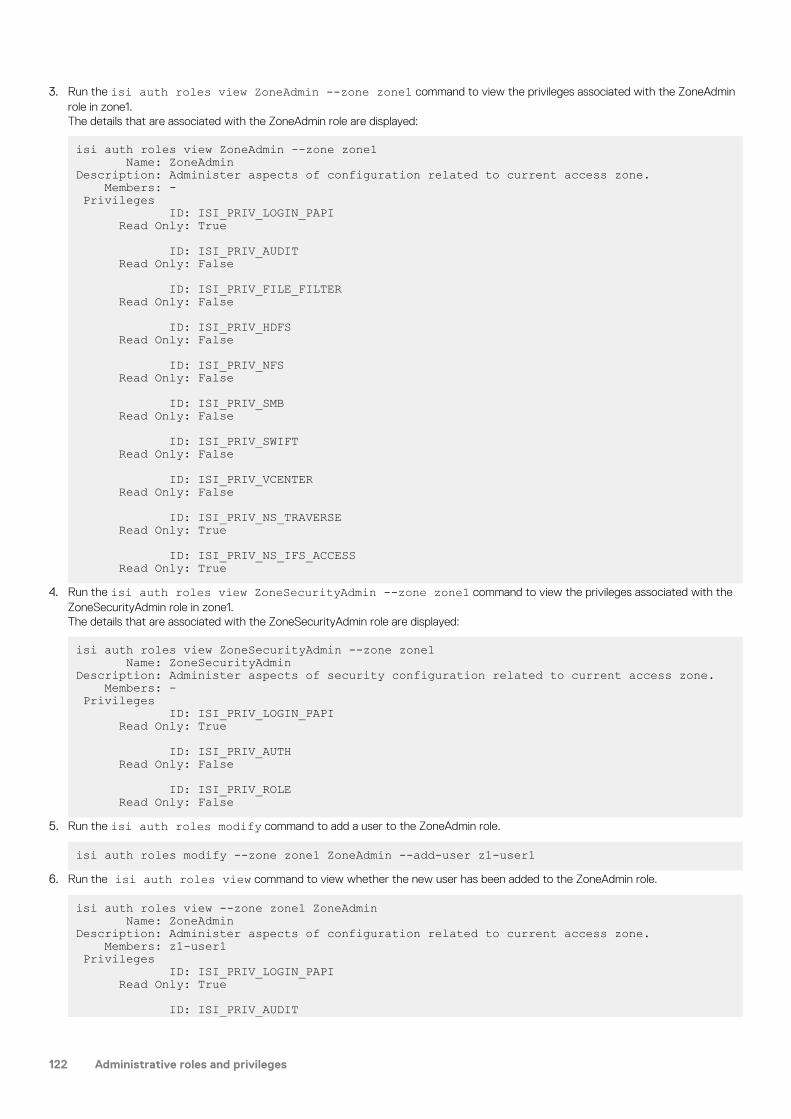
3. Run the isi auth roles view ZoneAdmin --zone zone1 command to view the privileges associated with the ZoneAdminrole in zone1.The details that are associated with the ZoneAdmin role are displayed:
isi auth roles view ZoneAdmin --zone zone1 Name: ZoneAdminDescription: Administer aspects of configuration related to current access zone. Members: - Privileges ID: ISI_PRIV_LOGIN_PAPI Read Only: True
ID: ISI_PRIV_AUDIT Read Only: False
ID: ISI_PRIV_FILE_FILTER Read Only: False
ID: ISI_PRIV_HDFS Read Only: False
ID: ISI_PRIV_NFS Read Only: False
ID: ISI_PRIV_SMB Read Only: False
ID: ISI_PRIV_SWIFT Read Only: False
ID: ISI_PRIV_VCENTER Read Only: False
ID: ISI_PRIV_NS_TRAVERSE Read Only: True
ID: ISI_PRIV_NS_IFS_ACCESS Read Only: True
4. Run the isi auth roles view ZoneSecurityAdmin --zone zone1 command to view the privileges associated with theZoneSecurityAdmin role in zone1.The details that are associated with the ZoneSecurityAdmin role are displayed:
isi auth roles view ZoneSecurityAdmin --zone zone1 Name: ZoneSecurityAdminDescription: Administer aspects of security configuration related to current access zone. Members: - Privileges ID: ISI_PRIV_LOGIN_PAPI Read Only: True
ID: ISI_PRIV_AUTH Read Only: False
ID: ISI_PRIV_ROLE Read Only: False
5. Run the isi auth roles modify command to add a user to the ZoneAdmin role.
isi auth roles modify --zone zone1 ZoneAdmin --add-user z1-user16. Run the isi auth roles view command to view whether the new user has been added to the ZoneAdmin role.
isi auth roles view --zone zone1 ZoneAdmin Name: ZoneAdminDescription: Administer aspects of configuration related to current access zone. Members: z1-user1 Privileges ID: ISI_PRIV_LOGIN_PAPI Read Only: True
ID: ISI_PRIV_AUDIT
122 Administrative roles and privileges

Read Only: False
ID: ISI_PRIV_FILE_FILTER Read Only: False
ID: ISI_PRIV_HDFS Read Only: False
ID: ISI_PRIV_NFS Read Only: False
ID: ISI_PRIV_SMB Read Only: False
ID: ISI_PRIV_SWIFT Read Only: False
ID: ISI_PRIV_VCENTER Read Only: False
ID: ISI_PRIV_NS_TRAVERSE Read Only: True
ID: ISI_PRIV_NS_IFS_ACCESS Read Only: True
7. Run the isi auth roles modify command to add a user to the ZoneSecurityAdmin role.
isi auth roles modify --zone zone1 ZoneSecurityAdmin --add-user z1-user28. Run the isi auth roles view command to view whether the new user has been added to the ZoneSecurityAdmin role.
isi auth roles view ZoneSecurityAdmin --zone zone1 Name: ZoneSecurityAdminDescription: Administer aspects of security configuration related to current access zone. Members: z1-user2 Privileges ID: ISI_PRIV_LOGIN_PAPI Read Only: True
ID: ISI_PRIV_AUTH Read Only: False
ID: ISI_PRIV_ROLE Read Only: False
Create a new role and add a userYou can create a new role and then add a user to the new role.
1. To create a new role, run the isi auth roles create command in zone1.
isi auth roles create --name Zone1SMBAdmin --zone zone12. To view the newly added role in the authentication list, run the isi auth roles list command.
isi auth roles list --zone zone1Name-----------------Zone1SMBAdminZoneAdminZoneSecurityAdmin-----------------Total: 3
3. To view the details associated with the new role, run the isi auth roles view command.
isi auth roles view Zone1SMBAdmin --zone zone1 Name: Zone1SMBAdminDescription: -
Administrative roles and privileges 123

Members: - Privileges ID: - Read Only: -
4. To add a privilege to the new role, run the isi auth roles modify command.
isi auth roles modify --zone zone1 Zone1SMBAdmin --add-priv ISI_PRIV_SMB
NOTE: You can also add a description to the new role using the isi auth roles modify command.
isi auth roles modify --zone zone1 Zone1SMBAdmin --description "Zone1 SMB Admin"5. To view whether the privilege and description of the new role were added, run the following command.
isi auth roles view Zone1SMBAdmin --zone zone1 Name: Zone1SMBAdminDescription: Zone1 SMB Admin Members: - Privileges ID: ISI_PRIV_SMB Read Only: False
6. To add a user to the new role, run the isi auth roles modify command again.
isi auth roles modify --zone zone1 SMBAdmin --add-user z1-user3
NOTE: You can also add a read-only privilege to the new user using the isi auth roles modify command.
isi auth roles modify --zone zone1 Zone1SMBAdmin --add-priv-ro ISI_PRIV_LOGIN_PAPI7. To view whether the new user was assigned the new role along with the read-only privilege, run the following command:
isi auth roles view Zone1SMBAdmin --zone zone1 Name: Zone1SMBAdminDescription: Zone1 SMB Admin Members: - Privileges ID: ISI_PRIV_LOGIN_PAPI Read Only: True
ID: ISI_PRIV_SMB Read Only: False
124 Administrative roles and privileges

Identity managementThis section contains the following topics:
Topics:
• Identity management overview• Identity types• Access tokens• Access token generation• Managing ID mappings• Managing user identities
Identity management overviewIn environments with several different types of directory services, OneFS maps the users and groups from the separate services toprovide a single unified identity on a cluster and uniform access control to files and directories, regardless of the incoming protocol. Thisprocess is called identity mapping.
Isilon clusters are frequently deployed in multiprotocol environments with multiple types of directory services, such as Active Directory andLDAP. When a user with accounts in multiple directory services logs in to a cluster, OneFS combines the user’s identities and privilegesfrom all the directory services into a native access token.
You can configure OneFS settings to include a list of rules for access token manipulation to control user identity and privileges. Forexample, you can set a user mapping rule to merge an Active Directory identity and an LDAP identity into a single token that works foraccess to files stored over both SMB and NFS. The token can include groups from Active Directory and LDAP. The mapping rules that youcreate can solve identity problems by manipulating access tokens in many ways, including the following examples:
• Authenticate a user with Active Directory but give the user a UNIX identity.• Select a primary group from competing choices in Active Directory or LDAP.• Disallow login of users that do not exist in both Active Directory and LDAP.
For more information about identity management, see the white paper Managing identities with the Isilon OneFS user mapping service at .
Identity typesOneFS supports three primary identity types, each of which you can store directly on the file system. Identity types are user identifier andgroup identifier for UNIX, and security identifier for Windows.
When you log on to a cluster, the user mapper expands your identity to include your other identities from all the directory services,including Active Directory, LDAP, and NIS. After OneFS maps your identities across the directory services, it generates an access tokenthat includes the identity information associated with your accounts. A token includes the following identifiers:
• A UNIX user identifier (UID) and a group identifier (GID). A UID or GID is a 32-bit number with a maximum value of 4,294,967,295.• A security identifier (SID) for a Windows user account. A SID is a series of authorities and sub-authorities ending with a 32-bit relative
identifier (RID). Most SIDs have the form S-1-5-21-<A>-<B>-<C>-<RID>, where <A>, <B>, and <C> are specific to a domain orcomputer and <RID> denotes the object in the domain.
• A primary group SID for a Windows group account.• A list of supplemental identities, including all groups in which the user is a member.
The token also contains privileges that stem from administrative role-based access control.
On an Isilon cluster, a file contains permissions, which appear as an access control list (ACL). The ACL controls access to directories, files,and other securable system objects.
When a user tries to access a file, OneFS compares the identities in the user’s access token with the file’s ACL. OneFS grants accesswhen the file’s ACL includes an access control entry (ACE) that allows the identity in the token to access the file and that does notinclude an ACE that denies the identity access. OneFS compares the access token of a user with the ACL of a file.
8
Identity management 125

NOTE: For more information about access control lists, including a description of the permissions and how they
correspond to POSIX mode bits, see the white paper titled EMC Isilon Multiprotocol Data Access with a Unified SecurityModel on the Dell EMC Isilon Technical Support web site.
When a name is provided as an identifier, it is converted into the corresponding user or group object and the correct identity type. You canenter or display a name in various ways:
• UNIX assumes unique case-sensitive namespaces for users and groups. For example, Name and name represent different objects.• Windows provides a single, case-insensitive namespace for all objects and also specifies a prefix to target an Active Directory domain;
for example, domain\name.• Kerberos and NFSv4 define principals, which require names to be formatted the same way as email addresses; for example,
Multiple names can reference the same object. For example, given the name support and the domain example.com, support, EXAMPLE\support and [email protected] are all names for a single object in Active Directory.
Access tokensAn access token is created when the user first makes a request for access.
Access tokens represent who a user is when performing actions on the cluster and supply the primary owner and group identities duringfile creation. Access tokens are also compared against the ACL or mode bits during authorization checks.
During user authorization, OneFS compares the access token, which is generated during the initial connection, with the authorization dataon the file. All user and identity mapping occurs during token generation; no mapping takes place during permissions evaluation.
An access token includes all UIDs, GIDs, and SIDs for an identity, in addition to all OneFS privileges. OneFS reads the information in thetoken to determine whether a user has access to a resource. It is important that the token contains the correct list of UIDs, GIDs, andSIDs. An access token is created from one of the following sources:
Source Authentication
Username • SMB impersonate user• Kerberized NFSv3• Kerberized NFSv4• NFS export user mapping• HTTP• FTP• HDFS
Privilege Attribute Certificate (PAC) • SMB NTLM• Active Directory Kerberos
User identifier (UID) • NFS AUTH_SYS mapping
Access token generationFor most protocols, the access token is generated from the username or from the authorization data that is retrieved duringauthentication.
The following steps present a simplified overview of the complex process through which an access token is generated:
Step 1: Useridentity lookup
Using the initial identity, the user is looked up in all configured authentication providers in the access zone, in theorder in which they are listed. The user identity and group list are retrieved from the authenticating provider. Next,additional group memberships that are associated with the user and group list are looked up for all otherauthentication providers. All of these SIDs, UIDs, or GIDs are added to the initial token.
NOTE: An exception to this behavior occurs if the AD provider is configured to call other
providers, such as LDAP or NIS.
Step 2: IDmapping
The user's identifiers are associated across directory services. All SIDs are converted to their equivalent UID/GIDand vice versa. These ID mappings are also added to the access token.
Step 3: Usermapping
Access tokens from other directory services are combined. If the username matches any user mapping rules, therules are processed in order and the token is updated accordingly.
126 Identity management

Step 4: On-diskidentitycalculation
The default on-disk identity is calculated from the final token and the global setting. These identities are used fornewly created files.
ID mappingThe Identity (ID) mapping service maintains relationship information between mapped Windows and UNIX identifiers to provide consistentaccess control across file sharing protocols within an access zone.
NOTE: ID mapping and user mapping are different services, despite the similarity in names.
During authentication, the authentication daemon requests identity mappings from the ID mapping service in order to create accesstokens. Upon request, the ID mapping service returns Windows identifiers mapped to UNIX identifiers or UNIX identifiers mapped toWindows identifiers. When a user authenticates to a cluster over NFS with a UID or GID, the ID mapping service returns the mappedWindows SID, allowing access to files that another user stored over SMB. When a user authenticates to the cluster over SMB with a SID,the ID mapping service returns the mapped UNIX UID and GID, allowing access to files that a UNIX client stored over NFS.
Mappings between UIDs or GIDs and SIDs are stored according to access zone in a cluster-distributed database called the ID map. Eachmapping in the ID map is stored as a one-way relationship from the source to the target identity type. Two-way mappings are stored ascomplementary one-way mappings.
Mapping Windows IDs to UNIX IDsWhen a Windows user authenticates with an SID, the authentication daemon searches the external Active Directory provider to look upthe user or group associated with the SID. If the user or group has only an SID in the Active Directory, the authentication daemon requestsa mapping from the ID mapping service.
NOTE: User and group lookups may be disabled or limited, depending on the Active Directory settings. You enable user
and group lookup settings through the isi auth ads modify command.
If the ID mapping service does not locate and return a mapped UID or GID in the ID map, the authentication daemon searches otherexternal authentication providers configured in the same access zone for a user that matches the same name as the Active Directory user.
If a matching user name is found in another external provider, the authentication daemon adds the matching user's UID or GID to theaccess token for the Active Directory user, and the ID mapping service creates a mapping between the UID or GID and the ActiveDirectory user's SID in the ID map. This is referred to as an external mapping.
NOTE: When an external mapping is stored in the ID map, the UID is specified as the on-disk identity for that user.
When the ID mapping service stores a generated mapping, the SID is specified as the on-disk identity.
If a matching user name is not found in another external provider, the authentication daemon assigns a UID or GID from the ID mappingrange to the Active Directory user's SID, and the ID mapping service stores the mapping in the ID map. This is referred to as a generatedmapping. The ID mapping range is a pool of UIDs and GIDs allocated in the mapping settings.
After a mapping has been created for a user, the authentication daemon retrieves the UID or GID stored in the ID map upon subsequentlookups for the user.
Mapping UNIX IDs to Windows IDsThe ID mapping service creates temporary UID-to-SID and GID-to-SID mappings only if a mapping does not already exist. The UNIX SIDsthat result from these mappings are never stored on disk.
UIDs and GIDs have a set of predefined mappings to and from SIDs.
If a UID-to-SID or GID-to-SID mapping is requested during authentication, the ID mapping service generates a temporary UNIX SID in theformat S-1-22-1-<UID> or S-1-22-2-<GID> by applying the following rules:
• For UIDs, the ID mapping service generates a UNIX SID with a domain of S-1-22-1 and a resource ID (RID) matching the UID. Forexample, the UNIX SID for UID 600 is S-1-22-1-600.
• For GIDs, the ID mapping service generates a UNIX SID with a domain of S-1-22-2 and an RID matching the GID. For example, theUNIX SID for GID 800 is S-1-22-2-800.
ID mapping rangesIn access zones with multiple external authentication providers, such as Active Directory and LDAP, it is important that the UIDs and GIDsfrom different providers that are configured in the same access zone do not overlap. Overlapping UIDs and GIDs between providers withinan access zone might result in some users gaining access to other users' directories and files.
Identity management 127

The range of UIDs and GIDs that can be allocated for generated mappings is configurable in each access zone through the isi authsettings mappings modify command. The default range for both UIDs and GIDs is 1000000–2000000 in each access zone.
Do not include commonly used UIDs and GIDs in your ID ranges. For example, UIDs and GIDs below 1000 are reserved for system accountsand should not be assigned to users or groups.
User mappingUser mapping provides a way to control permissions by specifying a user's security identifiers, user identifiers, and group identifiers. OneFSuses the identifiers to check file or group ownership.
With the user-mapping feature, you can apply rules to modify which user identity OneFS uses, add supplemental user identities, andmodify a user's group membership. The user-mapping service combines a user’s identities from different directory services into a singleaccess token and then modifies it according to the rules that you create.
NOTE: You can configure mapping rules on a per-zone basis. Mapping rules must be configured separately in each
access zone that uses them. OneFS maps users only during login or protocol access.
Default user mappingsDefault user mappings determine access if explicit user-mapping rules are not created.
If you do not configure rules, a user who authenticates with one directory service receives the identity information in other directoryservices when the account names are the same. For example, a user who authenticates with an Active Directory domain as Desktop\janeautomatically receives identities in the final access token for the corresponding UNIX user account for jane from LDAP or NIS.
In the most common scenario, OneFS is connected to two directory services, Active Directory and LDAP. In such a case, the defaultmapping provides a user with the following identity attributes:
• A UID from LDAP• The user SID from Active Directory• An SID from the default group in Active Directory
The user's groups come from Active Directory and LDAP, with the LDAP groups and the autogenerated group GID added to the list. Topull groups from LDAP, the mapping service queries the memberUid attribute. The user’s home directory, gecos, and shell come fromActive Directory.
Elements of user-mapping rulesYou combine operators with user names to create a user-mapping rule.
The following elements affect how the user mapper applies a rule:
• The operator, which determines the operation that a rule performs• Fields for usernames• Options• A parameter• Wildcards
User-mapping best practicesYou can follow best practices to simplify user mapping.
Use ActiveDirectory withRFC 2307 andWindows Servicesfor UNIX
Use Microsoft Active Directory with Windows Services for UNIX and RFC 2307 attributes to manage Linux, UNIX,and Windows systems. Integrating UNIX and Linux systems with Active Directory centralizes identity managementand eases interoperability, reducing the need for user-mapping rules. Make sure your domain controllers arerunning Windows Server 2003 or later.
Employ aconsistentusername strategy
The simplest configurations name users consistently, so that each UNIX user corresponds to a similarly namedWindows user. Such a convention allows rules with wildcard characters to match names and map them withoutexplicitly specifying each pair of accounts.
Do not useoverlapping IDranges
In networks with multiple identity sources, such as LDAP and Active Directory with RFC 2307 attributes, youshould ensure that UID and GID ranges do not overlap. It is also important that the range from which OneFSautomatically allocates UIDs and GIDs does not overlap with any other ID range. OneFS automatically allocates
128 Identity management

UIDs and GIDs from the range 1,000,000-2,000,000. If UIDs and GIDs overlap multiple directory services, someusers might gain access to other users’ directories and files.
Avoid commonUIDs and GIDs
Do not include commonly used UIDs and GIDs in your ID ranges. For example, UIDs and GIDs below 1000 arereserved for system accounts; do not assign them to users or groups.
Do not use UPNsin mapping rules
You cannot use a user principal name (UPN) in a user mapping rule. A UPN is an Active Directory domain andusername that are combined into an Internet-style name with an @ symbol, such as an email address:jane@example. If you include a UPN in a rule, the mapping service ignores it and may return an error. Instead,specify names in the format DOMAIN\user.com.
Group rules bytype and orderthem
The system processes every mapping rule by default, which can present problems when you apply a deny-all rule—for example, to deny access to all unknown users. In addition, replacement rules might interact with rules thatcontain wildcard characters. To minimize complexity, it is recommended that you group rules by type and organizethem in the following order:
1. Replacement rules: Specify all rules that replace an identity first to ensure that OneFS replaces all instances ofthe identity.
2. Join, add, and insert rules: After the names are set by any replacement operations, specify join, add, and insertrules to add extra identifiers.
3. Allow and deny rules: Specify rules that allow or deny access last.NOTE: Stop all processing before applying a default deny rule. To do so, create a rule that
matches allowed users but does nothing, such as an add operator with no field options, and has
the break option. After enumerating the allowed users, you can place a catchall deny at the end
to replace anybody unmatched with an empty user.
To prevent explicit rules from being skipped, in each group of rules, order explicit rules before rules that containwildcard characters.
Add the LDAP orNIS primary groupto thesupplementalgroups
When an Isilon cluster is connected to Active Directory and LDAP, a best practice is to add the LDAP primarygroup to the list of supplemental groups. This lets OneFS honor group permissions on files created over NFS ormigrated from other UNIX storage systems. The same practice is advised when an Isilon cluster is connected toboth Active Directory and NIS.
On-disk identityAfter the user mapper resolves a user's identities, OneFS determines an authoritative identifier for it, which is the preferred on-diskidentity.
OnesFS stores either UNIX or Windows identities in file metadata on disk. On-disk identity types are UNIX, SID, and native. Identities areset when a file is created or a file's access control data is modified. Almost all protocols require some level of mapping to operate correctly,so choosing the preferred identity to store on disk is important. You can configure OneFS to store either the UNIX or the Windowsidentity, or you can allow OneFS to determine the optimal identity to store.
On-disk identity types are UNIX, SID, and native. Although you can change the type of on-disk identity, the native identity is best for anetwork with UNIX and Windows systems. In native on-disk identity mode, setting the UID as the on-disk identity improves NFSperformance.
NOTE: The SID on-disk identity is for a homogeneous network of Windows systems managed only with Active Directory.
When you upgrade from a version earlier than OneFS 6.5, the on-disk identity is set to UNIX. When you upgrade from
OneFS 6.5 or later, the on-disk identity setting is preserved. On new installations, the on-disk identity is set to native.
The native on-disk identity type allows the OneFS authentication daemon to select the correct identity to store on disk by checking forthe identity mapping types in the following order:
Order Mapping type Description
1 Algorithmic mapping An SID that matches S-1-22-1-UID or S-1-22-2-GID in the internal ID mappingdatabase is converted back to the corresponding UNIX identity, and the UID andGID are set as the on-disk identity.
2 External mapping A user with an explicit UID and GID defined in a directory service (such as ActiveDirectory with RFC 2307 attributes, LDAP, NIS, or the OneFS file provider orlocal provider) has the UNIX identity set as the on-disk identity.
Identity management 129

Order Mapping type Description
3 Persistent mapping Mappings are stored persistently in the identity mapper database. An identitywith a persistent mapping in the identity mapper database uses the destinationof that mapping as the on-disk identity, which occurs primarily with manual IDmappings. For example, if there is an ID mapping of GID:10000 to S-1-5-32-545,a request for the on-disk storage of GID:10000 returns S-1-5-32-545.
4 No mapping If a user lacks a UID or GID even after querying the other directory services andidentity databases, its SID is set as the on-disk identity. In addition, to make surea user can access files over NFS, OneFS allocates a UID and GID from a presetrange of 1,000,000 to 2,000,000. In native on-disk identity mode, a UID or GIDthat OneFS generates is never set as the on-disk identity.
NOTE: If you change the on-disk identity type, you should run the PermissionRepair job with the Convert repair type
selected to make sure that the disk representation of all files is consistent with the changed setting. For more
information, see the Run the PermissionRepair job section.
Managing ID mappingsYou can create, modify, and delete identity mappings and configure ID mapping settings.
Create an identity mappingYou can create a manual identity mapping between source and target identities or automatically generate a mapping for a source identity.
This procedure is available only through the command-line interface.
1. Open a secure shell (SSH) connection to any node in the cluster and log in.2. Run the isi auth mapping create command.
The following command specifies IDs of source and target identities in the zone3 access zone to create a two-way mapping betweenthe identities:
isi auth mapping create --2way --source-sid=S-1-5-21-12345 \--target-uid=5211 --zone=zone3
Modify an identity mappingYou can modify the configuration of an identity mapping.
This procedure is available only through the command-line interface.
1. Open a secure shell (SSH) connection to any node in the cluster and log in.2. Run the isi auth mapping modify command.
The following command modifies the mapping of the user with UID 4236 in the zone3 access zone to include a reverse, 2-waymapping between the source and target identities:
isi auth mapping modify --source-uid=4236 \--target-sid=S-1-5-21-12345 --zone=zone3 --2way
Delete an identity mappingYou can delete one or more identity mappings.
This procedure is available only through the command-line interface.
1. Open a secure shell (SSH) connection to any node in the cluster and log in.2. Run the isi auth mapping delete command.
The following command deletes all identity mappings in the zone3 access zone:
isi auth mapping delete --all --zone=zone3
130 Identity management

The following command deletes all identity mappings in the zone3 access zone that were both created automatically and include a UIDor GID from an external authentication source:
isi auth mapping delete --all --only-external --zone=zone3
The following command deletes the identity mapping of the user with UID 4236 in the zone3 access zone:
isi auth mapping delete --source-uid=4236 --zone=zone3
View an identity mappingYou can display mapping information for a specific identity.
This procedure is available only through the command-line interface.
1. Open a secure shell (SSH) connection to any node in the cluster and log in.2. Run the isi auth mapping view command.
The following command displays mappings for the user with UID 4236 in the zone3 access zone:
isi auth mapping view --uid=4236 --zone=zone3
The system displays output similar to the following example:
Name: user_36 On-disk: UID: 4236Unix uid: 4236Unix gid: -100000 SMB: S-1-22-1-4236
Flush the identity mapping cacheYou can flush the ID map cache to remove in-memory copies of all or specific identity mappings.
Modifications to ID mappings may cause the cache to become out of sync and users might experience slowness or stalls whenauthenticating. You can flush the cache to synchronize the mappings.
This procedure is available only through the command-line interface.
1. Open a secure shell (SSH) connection to any node in the cluster and log in.2. Run the isi auth mapping flush command.
The following command flushes all identity mappings on the cluster:
isi auth mapping flush --all
The following command flushes the mapping of the user with UID 4236 in the zone3 access zone:
isi auth mapping flush --source-uid-4236 --zone=zone3
View a user tokenYou can view the contents of an access token generated for a user during authentication.
This procedure is available only through the command-line interface.
1. Open a secure shell (SSH) connection to any node in the cluster and log in.2. Run the isi auth mapping token command.
The following command displays the access token of a user with UID 4236 in the zone3 access zone:
isi auth mapping token --uid=4236 --zone=zone3
The system displays output similar to the following example:
User Name: user_36 UID: 4236 SID: S-1-22-1-4236
Identity management 131

On Disk: 4236ZID: 3Zone: zone3Privileges: -Primary Group Name: user_36 GID: 4236 SID: S-1-22-2-4236 On Disk: 4236
Configure identity mapping settingsYou can enable or disable automatic allocation of UIDs and GIDS and customize the range of ID values in each access zone. The defaultrange is 1000000–2000000.
This procedure is available only through the command-line interface.
1. Open a secure shell (SSH) connection to any node in the cluster and log in.2. Run the isi auth settings mapping modify command.
The following command enables automatic allocation of both UIDs and GIDs in the zone3 access zone and sets their allocation rangesto 25000–50000:
isi auth settings mapping modify --gid-range-enabled=yes \--gid-range-min=25000 --gid-range-max=50000 --uid-range-enabled=yes \--uid-range-min=25000 --uid-range-max=50000 --zone=zone3
View identity mapping settingsYou can view the current configuration of identity mapping settings in each zone.
This procedure is available only through the command-line interface.
1. Open a secure shell (SSH) connection to any node in the cluster and log in.2. Run the isi auth settings mapping view command.
The following command displays the current settings in the zone3 access zone:
isi auth settings mapping view --zone=zone3
The system displays output similar to the following example:
GID Range Enabled: Yes GID Range Min: 25000 GID Range Max: 50000UID Range Enabled: Yes UID Range Min: 25000 UID Range Max: 50000
Managing user identitiesYou can manage user identities by creating user-mapping rules.
When you create user-mapping rules, it is important to remember the following information:
• You can only create user-mapping rules if you are connected to the cluster through the System zone; however, you can apply user-mapping rules to specific access zones. If you create a user-mapping rule for a specific access zone, the rule applies only in thecontext of its zone.
• When you change user-mapping on one node, OneFS propagates the change to the other nodes.• After you make a user-mapping change, the OneFS authentication service reloads the configuration.
132 Identity management

View user identityYou can view the identities and group membership that a specified user has within the Active Directory and LDAP directory services,including the user's security identifier (SID) history.
This procedure must be performed through the command-line interface (CLI).
NOTE: The OneFS user access token contains a combination of identities from Active Directory and LDAP if both
directory services are configured. You can run the following commands to discover the identities that are within each
specific directory service.
1. Establish an SSH connection to any node in the cluster.2. View a user identity from Active Directory only by running the isi auth users view command.
The following command displays the identity of a user named stand in the Active Directory domain named YORK:
isi auth users view --user=YORK\\stand --show-groups
The system displays output similar to the following example:
Name: YORK\stand DN: CN=stand,CN=Users,DC=york,DC=hull,DC=example,DC=com DNS Domain: york.hull.example.com Domain: YORK Provider: lsa-activedirectory-provider:YORK.HULL.EXAMPLE.COMSam Account Name: stand UID: 4326 SID: S-1-5-21-1195855716-1269722693-1240286574-591111 Primary Group ID : GID:1000000 Name : YORK\york_sh_udg Additional Groups: YORK\sd-york space group YORK\york_sh_udg YORK\sd-york-group YORK\sd-group YORK\domain users
3. View a user identity from LDAP only by running the isi auth users view command.The following command displays the identity of an LDAP user named stand:
isi auth user view --user=stand --show-groups
The system displays output similar to the following example:
Name: stand DN: uid=stand,ou=People,dc=colorado4,dc=hull,dc=example,dc=comDNS Domain: - Domain: LDAP_USERS Provider: lsa-ldap-provider:Unix LDAPSam Account Name: stand UID: 4326 SID: S-1-22-1-4326 Primary Group ID : GID:7222 Name : stand Additional Groups: stand sd-group sd-group2
Create a user-mapping ruleYou can create user-mapping rules to manage user identities on the cluster.
You can create the first mapping rule with the --user-mapping-rules option for the isi zone zones modify Systemcommand. If you try to add a second rule with the command above, however, it replaces the existing rule rather than adding the new ruleto the list of rules. To add more rules to the list of rules, you must use the --add-user-mapping-rules option with the isi zonezones modify System command.
NOTE: If you do not specify an access zone, user-mapping rules are created in the System zone.
Identity management 133

1. To create a rule to merge the Active Directory user with a user from LDAP, run the following command, where <user-a> and <user-b>are placeholders for the identities to be merged; for example, user_9440 and lduser_010, respectively:
isi zone zones modify System --add-user-mapping-rules \ "<DOMAIN> <user-a> &= <user-b>"
Run the following command to view the rule:
isi zone zones view System
If the command runs successfully, the system displays the mapping rule, which is visible in the User Mapping Rules line of the output:
Name: System Cache Size: 4.77M Map Untrusted: SMB Shares: - Auth Providers: - Local Provider: Yes NetBIOS Name: All SMB Shares: Yes All Auth Providers: Yes User Mapping Rules: <DOMAIN>\<user_a> &= <user_b>Home Directory Umask: 0077 Skeleton Directory: /usr/share/skel Zone ID: 1
2. To verify the changes to the token, run a command similar to the following example:
isi auth mapping token <DOMAIN>\\<user-a>
If the command runs successfully, the system displays output similar to the following example:
User Name : <DOMAIN>\<user-a> UID : 1000201 SID : S-1-5-21-1195855716-1269722693-1240286574-11547 ZID: 1 Zone: System Privileges: -Primary Group Name : <DOMAIN>\domain users GID : 1000000 SID : S-1-5-21-1195855716-1269722693-1240286574-513Supplemental Identities Name : Users GID : 1545 SID : S-1-5-32-545
Name : lduser_010 UID : 10010 SID : S-1-22-1-10010
Name : example GID : 10000 SID : S-1-22-2-10000
Name : ldgroup_20user GID : 10026 SID : S-1-22-2-10026
Merge Windows and UNIX tokensYou can use either the join or append operator to merge two user names into a single token.
When Windows and UNIX user names do not match across directory services, you can write user-mapping rules that use either the join orthe append operator to merge two user names into a single token. For example, if a user's Windows username is win_bob and the usersUNIX username is UNIX_bob, you can join or append them.
When you append an account to another account, the append operator adds information from one identity to another. OneFS appendsthe fields that the options specify from the source identity to the target identity. OneFS appends the identifiers to the additional group list.
134 Identity management

1. Establish an SSH connection to any node in the cluster.2. Write a rule similar to the following example to join the Windows and UNIX user names, where <win-username> and <UNIX-
username> are placeholders for the user's Windows and UNIX accounts:
MYDOMAIN\<win-username> &= <UNIX-username> []
3. Write a rule similar to the following example to append the UNIX account to the Windows account with the groups option:
MYDOMAIN\<win-username> ++ <UNIX-username> [groups]
Retrieve the primary group from LDAPYou can create a user-mapping rule to insert or append primary group information from LDAP into a user's access token.
By default, the user-mapping service combines information from AD and LDAP but gives precedence to the information from AD. Mappingrules control how OneFS combines the information. You can retrieve the primary group information from LDAP instead of AD.
1. Establish an SSH connection to any node in the cluster.2. Write a rule similar to the following example to insert information from LDAP into a user's access token:
*\* += * [group]
3. Write a rule similar to the following example to append other information from LDAP to a user's access token:
*\* ++ * [user,groups]
Mapping rule optionsMapping rules can contain options that target the fields of an access token.
A field represents an aspect of a cross-domain access token, such as the primary UID and primary user SID from a user that you select.You can see some of the fields in the OneFS web administration interface. User in the web administration interface is the same asusername. You can also see fields in an access token by running the command isi auth mapping token.
When you create a rule, you can add an option to manipulate how OneFS combines aspects of two identities into a single token. Forexample, an option can force OneFS to append the supplement groups to a token.
A token includes the following fields that you can manipulate with user mapping rules:
• username• unix_name• primary_uid• primary_user_sid• primary_gid• primary_group_sid• additional_ids (includes supplemental groups)
Options control how a rule combines identity information in a token. The break option is the exception: It stops OneFS from processingadditional rules.
Although several options can apply to a rule, not all options apply to all operators. The following table describes the effect of each optionand the operators that they work with.
Option Operator Description
user insert, append Copies the primary UID and primary user SID, if they exist, to thetoken.
groups insert, append Copies the primary GID and primary group SID, if they exist, to thetoken.
Identity management 135

Option Operator Description
groups insert, append Copies all the additional identifiers to the token. The additionalidentifiers exclude the primary UID, the primary GID, the primaryuser SID, and the primary group SID.
default_user all operators except removegroups
If the mapping service fails to find the second user in a rule, theservice tries to find the username of the default user. The name ofthe default user cannot include wildcards. When you set the optionfor the default user in a rule with the command-line interface, youmust set it with an underscore: default_user.
break all operators Stops the mapping service from applying rules that follow theinsertion point of the break option. The mapping service generatesthe final token at the point of the break.
Mapping rule operatorsThe operator determines what a mapping rule does.
You can create user-mapping rules through either the web-administration interface, where the operators are spelled out in a list, or fromthe command-line interface.
When you create a mapping rule with the OneFS command-line interface (CLI), you must specify an operator with a symbol. The operatoraffects the direction in which the mapping service processes a rule. For more information about creating a mapping rule, see the whitepaper Managing identities with the Isilon OneFS user mapping service. The following table describes the operators that you can use in amapping rule.
A mapping rule can contain only one operator.
Operator Web interface CLI Direction Description
append Append fields from auser
++ Left-to-right Modifies an access tokenby adding fields to it. Themapping service appendsthe fields that arespecified in the list ofoptions (user, group,groups) to the firstidentity in the rule. Thefields are copied from thesecond identity in therule. All appendedidentifiers becomemembers of theadditional groups list. Anappend rule without anoption performs only alookup operation; youmust include an option toalter a token.
insert Insert fields from auser
+= Left-to-right Modifies an existingaccess token by addingfields to it. Fieldsspecified in the optionslist (user, group, groups)are copied from the newidentity and inserted intothe identity in the token.When the rule inserts aprimary user or primarygroup, it become the newprimary user and primarygroup in the token. Theprevious primary user
136 Identity management

Operator Web interface CLI Direction Description
and primary group moveto the additionalidentifiers list. Modifyingthe primary user leavesthe token’s usernameunchanged. Wheninserting the additionalgroups from an identity,the service adds the newgroups to the existinggroups.
replace Replace one user witha different user
=> Left-to-right Removes the token andreplaces it with the newtoken that is identified bythe second username. Ifthe second username isempty, the mappingservice removes the firstusername in the token,leaving no username. If atoken contains nousername, OneFS deniesaccess with a no suchuser error.
remove groups Remove supplementalgroups from a user
-- Unary Modifies a token byremoving thesupplemental groups.
join Join two userstogether
&= Bidirectional Inserts the new identityinto the token. If the newidentity is the seconduser, the mapping serviceinserts it after theexisting identity;otherwise, the serviceinserts it before theexisting identity. Thelocation of the insertionpoint is relevant whenthe existing identity isalready the first in the listbecause OneFS uses thefirst identity to determinethe ownership of new filesystem objects.
Identity management 137

Home directoriesThis section contains the following topics:
Topics:
• Home directories overview• Home directory permissions• Authenticating SMB users• Home directory creation through SMB• Home directory creation through SSH and FTP• Home directory creation in a mixed environment• Interactions between ACLs and mode bits• Default home directory settings in authentication providers• Supported expansion variables• Domain variables in home directory provisioning
Home directories overviewWhen you create a local user, OneFS automatically creates a home directory for the user. OneFS also supports dynamic home directoryprovisioning for users who access the cluster by connecting to an SMB share or by logging in through FTP or SSH.
Regardless of the method by which a home directory was created, you can configure access to the home directory through a combinationof SMB, SSH, and FTP.
Home directory permissionsYou can set up a user's home directory with a Windows ACL or with POSIX mode bits, which are then converted into a synthetic ACL.The method by which a home directory is created determines the initial permissions that are set on the home directory.
When you create a local user, the user's home directory is created with mode bits by default.
For users who authenticate against external sources, you can specify settings to create home directories dynamically at login time. If ahome directory is created during a login through SSH or FTP, it is set up with mode bits; if a home directory is created during an SMBconnection, it receives either mode bits or an ACL. For example, if an LDAP user first logs in through SSH or FTP, the user's homedirectory is created with mode bits. If the same user first connects through an SMB share, the home directory is created with thepermissions indicated by the configured SMB settings. If the --inheritable-path-acl option is enabled, an ACL is generated;otherwise, mode bits are used.
Authenticating SMB usersYou can authenticate SMB users from authentication providers that can handle NT hashes.
SMB sends an NT password hash to authenticate SMB users, so only users from authentication providers that can handle NT hashes canlog in over SMB. The following OneFS-supported authentication providers can handle NT hashes:
• Active Directory• Local• LDAPSAM (LDAP with Samba extensions enabled)
9
138 Home directories

Home directory creation through SMBYou can create SMB shares by including expansion variables in the share path. Expansion variables give users to access their homedirectories by connecting to the share. You can also enable dynamic provisioning of home directories that do not exist at SMB connectiontime.
NOTE: Share permissions are checked when files are accessed, before the underlying file system permissions are
checked. Either of these permissions can prevent access to the file or directory.
Create home directories with expansion variablesYou can configure settings with expansion variables to create SMB share home directories.
When users access the cluster over SMB, home directory access is through SMB shares. You can configure settings with a path that usesa variable expansion syntax, allowing a user to connect to their home directory share.
NOTE: Home directory share paths must begin with /ifs/ and must be in the root path of the access zone in which the
home directory SMB share is created.
In the following commands, the --allow-variable-expansion option is enabled to indicate that %U should be expanded to theuser name, which is user411 in this example. The --auto-create-directory option is enabled to create the directory if it does notexist:
isi smb shares create HOMEDIR --path=/ifs/home/%U \ --allow-variable-expansion=yes --auto-create-directory=yes isi smb shares permission modify HOMEDIR --wellknown Everyone \ --permission-type allow --permission full isi smb shares view HOMEDIR
The system displays output similar to the following example:
Share Name: HOMEDIR Path: /ifs/home/%U Description: Client-side Caching Policy: manualAutomatically expand user names or domain names: TrueAutomatically create home directories for users: True Browsable: TruePermissions:Account Account Type Run as Root Permission Type Permission------------------------------------------------------------Everyone wellknown False allow full ------------------------------------------------------------Total: 1...When user411 connects to the share with the net use command, the user's home directory is created at /ifs/home/user411. Onuser411's Windows client, the net use m: command connects /ifs/home/user411 through the HOMEDIR share:
net use m: \\cluster.company.com\HOMEDIR /u:user4111. Run the following commands on the cluster with the --allow-variable-expansion option enabled. The %U expansion variable
expands to the user name, and the --auto-create-directory option is enabled to create the directory if it does not exist:
isi smb shares create HOMEDIR --path=/ifs/home/%U \ --allow-variable-expansion=yes --auto-create-directory=yes isi smb shares permission modify HOMEDIR --wellknown Everyone \ --permission-type allow --permission full
2. Run the following command to view the home directory settings:
isi smb shares view HOMEDIR
The system displays output similar to the following example:
Share Name: HOMEDIR Path: /ifs/home/%U Description: Client-side Caching Policy: manual
Home directories 139

Automatically expand user names or domain names: TrueAutomatically create home directories for users: True Browsable: TruePermissions:Account Account Type Run as Root Permission Type Permission------------------------------------------------------------Everyone wellknown False allow full ------------------------------------------------------------Total: 1...If user411 connects to the share with the net use command, user411's home directory is created at /ifs/home/user411. Onuser411's Windows client, the net use m: command connects /ifs/home/user411 through the HOMEDIR share, mapping theconnection similar to the following example:
net use m: \\cluster.company.com\HOMEDIR /u:user411
Create home directories with the --inheritable-path-acloptionYou can enable the --inheritable-path-acl option on a share to specify that it is to be inherited on the share path if the parentdirectory has an inheritable ACL.
To perform most configuration tasks, you must log on as a member of the SecurityAdmin role.
By default, an SMB share's directory path is created with a synthetic ACL based on mode bits. You can enable the --inheritable-path-acl option to use the inheritable ACL on all directories that are created, either at share creation time or for those dynamicallyprovisioned when connecting to that share.
1. Run commands similar to the following examples to enable the --inheritable-path-acl option on the cluster to dynamicallyprovision a user home directory at first connection to a share on the cluster:
isi smb shares create HOMEDIR_ACL --path=/ifs/home/%U \ --allow-variable-expansion=yes --auto-create-directory=yes \ --inheritable-path-acl=yes
isi smb shares permission modify HOMEDIR_ACL \ --wellknown Everyone \ --permission-type allow --permission full
2. Run a net use command, similar to the following example, on a Windows client to map the home directory for user411:
net use q: \\cluster.company.com\HOMEDIR_ACL /u:user4113. Run a command similar to the following example on the cluster to view the inherited ACL permissions for the user411 share:
cd /ifs/home/user411ls -lde .
The system displays output similar to the following example:
drwx------ + 2 user411 Isilon Users 0 Oct 19 16:23 ./ OWNER: user:user411 GROUP: group:Isilon Users CONTROL:dacl_auto_inherited,dacl_protected 0: user:user411 allow dir_gen_all,object_inherit,container_inherit
Create special home directories with the SMB share %UvariableThe special SMB share name %U enables you to create a home-directory SMB share that appears the same as a user's user name.
You typically set up a %U SMB share with a share path that includes the %U expansion variable. If a user attempts to connect to a sharematching the login name and it does not exist, the user connects to the %U share instead and is directed to the expanded path for the%U share.
140 Home directories

NOTE: If another SMB share exists that matches the user's name, the user connects to the explicitly named share
rather than to the %U share.
Run the following command to create a share that matches the authenticated user login name when the user connects to the share:
isi smb share create %U /ifs/home/%U \ --allow-variable-expansion=yes --auto-create-directory=yes \ --zone=System
After running this command, user Zachary will see a share named 'zachary' rather than '%U', and when Zachary tries to connect to theshare named 'zachary', he will be directed to /ifs/home/zachary. On a Windows client, if Zachary runs the following commands, hesees the contents of his /ifs/home/zachary directory:
net use m: \\cluster.ip\zachary /u:zachary cd m:dir
Similarly, if user Claudia runs the following commands on a Windows client, she sees the directory contents of /ifs/home/claudia:
net use m: \\cluster.ip\claudia /u:claudia cd m: dir
Zachary and Claudia cannot access one another's home directory because only the share 'zachary' exists for Zachary and only the share'claudia' exists for Claudia.
Home directory creation through SSH and FTPYou can configure home directory support for users who access the cluster through SSH or FTP by modifying authentication providersettings.
Set the SSH or FTP login shellYou can use the --login-shell option to set the default login shell for the user.
By default, the --login-shell option, if specified, overrides any login-shell information provided by the authentication provider, exceptwith Active Directory. If the --login-shell option is specified with Active Directory, it simply represents the default login shell if theActive Directory server does not provide login-shell information.
NOTE: The following examples refer to setting the login shell to /bin/bash. You can also set the shell to /bin/rbash.
1. Run the following command to set the login shell for all local users to /bin/bash:
isi auth local modify System --login-shell /bin/bash
2. Run the following command to set the default login shell for all Active Directory users in your domain to /bin/bash:
isi auth ads modify YOUR.DOMAIN.NAME.COM --login-shell /bin/bash
Set SSH/FTP home directory permissionsYou can specify home directory permissions for a home directory that is accessed through SSH or FTP by setting a umask value.
To perform most configuration tasks, you must log on as a member of the SecurityAdmin role.
When a user's home directory is created at login through SSH or FTP, it is created using POSIX mode bits. The permissions setting on auser's home directory is set to 0755, then masked according to the umask setting of the user's access zone to further limit permissions.You can modify the umask setting for a zone with the --home-directory-umask option, specifying an octal number as the umaskvalue.
Home directories 141

1. Run the following command to view umask setting:
isi zone zones view System
The system displays output similar to the following example:
Name: System Path: /ifs Groupnet: groupnet0 Map Untrusted: - Auth Providers: lsa-local-provider:System, lsa-file-provider:System NetBIOS Name: - User Mapping Rules: - Home Directory Umask: 0077 Skeleton Directory: /usr/share/skel Cache Entry Expiry: 4H Negative Cache Entry Expiry: 1m Zone ID: 1In the command result, you can see the default setting for Home Directory Umask for the created home directory is 0700, whichis equivalent to (0755 & ~(077)). You can modify the Home Directory Umask setting for a zone with the --home-directory-umask option, specifying an octal number as the umask value. This value indicates the permissions that are to bedisabled, so larger mask values indicate fewer permissions. For example, a umask value of 000 or 022 yields created home directorypermissions of 0755, whereas a umask value of 077 yields created home directory permissions of 0700.
2. Run a command similar to the following example to allow a group/others write/execute permission in a home directory:
isi zone zones modify System --home-directory-umask=022
In this example, user home directories will be created with mode bits 0755 masked by the umask field, set to the value of 022.Therefore, user home directories will be created with mode bits 0755, which is equivalent to (0755 & ~(022)).
Set SSH/FTP home directory creation optionsYou can configure home directory support for a user who accesses the cluster through SSH or FTP by specifying authentication provideroptions.
1. Run the following command to view settings for an Active Directory authentication provider on the cluster:
isi auth ads list
The system displays output similar to the following example:
Name Authentication Status DC Name Site ---------------------------------------------------------YOUR.DOMAIN.NAME.COM Yes online - SEA---------------------------------------------------------Total: 1
2. Run the isi auth ads modify command with the --home-directory-template and --create-home-directoryoptions.
isi auth ads modify YOUR.DOMAIN.NAME.COM \--home-directory-template=/ifs/home/ADS/%D/%U \--create-home-directory=yes
3. Run the isi auth ads view command with the --verbose option.The system displays output similar to the following example:
Name: YOUR.DOMAIN.NAME.COM NetBIOS Domain: YOUR ... Create Home Directory: Yes Home Directory Template: /ifs/home/ADS/%D/%U Login Shell: /bin/sh
4. Run the id command.The system displays output similar to the following example:
142 Home directories

uid=1000008(<your-domain>\user_100) gid=1000000(<your-domain>\domain users) groups=1000000(<your-domain>\domain users),1000024(<your-domain>\c1t),1545(Users)
5. Optional: To verify this information from an external UNIX node, run the ssh command from an external UNIX node.For example, the following command would create /ifs/home/ADS/<your-domain>/user_100 if it did not previously exist:
ssh <your-domain>\\[email protected]
Provision home directories with dot filesYou can provision home directories with dot files.
To perform most configuration tasks, you must log on as a member of the SecurityAdmin role.
The skeleton directory, which is located at /usr/share/skel by default, contains a set of files that are copied to the user's homedirectory when a local user is created or when a user home directory is dynamically created during login. Files in the skeleton directory thatbegin with dot. are renamed to remove the dot prefix when they are copied to the user's home directory. For example, dot.cshrc iscopied to the user's home directory as .cshrc. This format enables dot files in the skeleton directory to be viewable through thecommand-line interface without requiring the ls -a command.
For SMB shares that might use home directories that were provisioned with dot files, you can set an option to prevent users who connectto the share through SMB from viewing the dot files.
1. Run the following command to display the default skeleton directory in the System access zone:
isi zone zones view System
The system displays output similar to the following example:
Name: System... Skeleton Directory: /usr/share/skel
2. Run the isi zone zones modify command to modify the default skeleton directory.The following command modifies the default skeleton directory, /usr/share/skel, in an access zone, where System is the valuefor the <zone> option and /usr/share/skel2 is the value for the <path> option:
isi zone zones modify System --skeleton-directory=/usr/share/skel2
Home directory creation in a mixed environmentIf a user logs in through both SMB and SSH, it is recommended that you configure home directory settings so the path template is thesame for the SMB share and each authentication provider against which the user is authenticating through SSH.
Interactions between ACLs and mode bitsHome directory setup is determined by several factors, including how users authenticate and the options that specify home directorycreation.
A user's home directory may be set up with either ACLs or POSIX mode bits, which are converted into a synthetic ACL. The directory of alocal user is created when the local user is created, and the directory is set up with POSIX mode bits by default. Directories can bedynamically provisioned at log in for users who authenticate against external sources, and in some cases for users who authenticateagainst the File provider. In this situation, the user home directory is created according to how the user first logs in.
For example, if an LDAP user first logs in through SSH or FTP and the user home directory is created, it is created with POSIX mode bits.If that same user first connects through an SMB home directory share, the home directory is created as specified by the SMB optionsettings. If the --inherited-path-acl option is enabled, ACLs are generated. Otherwise, POSIX mode bits are used.
Home directories 143

Default home directory settings in authenticationprovidersThe default settings that affect how home directories are set up differ, based on the authentication provider that the user authenticatesagainst.
Authentication provider Home directory Home directory creation UNIX login shell
Local • --home-directory-template=/ifs/home/%U
• --create-home-directory=yes
• --login-shell=/bin/sh
Enabled /bin/sh
File • --home-directory-template=""
• --create-home-directory=no
Disabled None
Active Directory • --home-directory-template=/ifs/home/%D/%U
• --create-home-directory=no
• --login-shell=/bin/shNOTE: If available,provider informationoverrides this value.
Disabled /bin/sh
LDAP • --home-directory-template=""
• --create-home-directory=no
Disabled None
NIS • --home-directory-template=""
• --create-home-directory=no
Disabled None
Related References
Supported expansion variables on page 144
Supported expansion variablesYou can include expansion variables in an SMB share path or in an authentication provider's home directory template.
OneFS supports the following expansion variables. You can improve performance and reduce the number of shares to be managed whenyou configure shares with expansion variables. For example, you can include the %U variable for a share rather than create a share foreach user. When a %U is included in the name so that each user's path is different, security is still ensured because each user can viewand access only his or her home directory.
NOTE: When you create an SMB share through the web administration interface, you must select the Allow Variable
Expansion check box or the string is interpreted literally by the system.
144 Home directories

Variable Value Description
%U User name (for example,user_001)
Expands to the user name to allow different users to use differenthome directories. This variable is typically included at the end ofthe path. For example, for a user named user1, the path /ifs/home/%U is mapped to /ifs/home/user1.
%D NetBIOS domain name (forexample, YORK forYORK.EAST.EXAMPLE.COM)
Expands to the user's domain name, based on the authenticationprovider:
• For Active Directory users, %D expands to the Active DirectoryNetBIOS name.
• For local users, %D expands to the cluster name in uppercasecharacters. For example, for a cluster named cluster1, %Dexpands to CLUSTER1.
• For users in the System file provider, %D expands toUNIX_USERS.
• For users in other file providers, %D expands to FILE_USERS.• For LDAP users, %D expands to LDAP_USERS.• For NIS users, %D expands to NIS_USERS.
%Z Zone name (for example,ZoneABC)
Expands to the access zone name. If multiple zones are activated,this variable is useful for differentiating users in separate zones.For example, for a user named user1 in the System zone, thepath /ifs/home/%Z/%U is mapped to /ifs/home/System/user1.
%L Host name (cluster host namein lowercase)
Expands to the host name of the cluster, normalized to lowercase.Limited use.
%0 First character of the user name Expands to the first character of the user name.
%1 Second character of the username
Expands to the second character of the user name.
%2 Third character of the username
Expands to the third character of the user name.
NOTE: If the user name includes fewer than three characters, the %0, %1, and %2 variables wrap around. For example,
for a user named ab, the variables maps to a, b, and a, respectively. For a user named a, all three variables map to a.
Domain variables in home directory provisioningYou can use domain variables to specify authentication providers when provisioning home directories.
The domain variable (%D) is typically used for Active Directory users, but it has a value set that can be used for other authenticationproviders. %D expands as described in the following table for the various authentication providers.
Authenticated user %D expansion
Active Directory user Active Directory NetBIOS name—for example, YORK for provider YORK.EAST.EXAMPLE.COM.
Local user The cluster name in all-uppercase characters—for example, if the cluster is named MyCluster, %Dexpands to MYCLUSTER.
File user • UNIX_USERS (for System file provider)• FILE_USERS (for all other file providers)
LDAP user LDAP_USERS (for all LDAP authentication providers)
NIS user NIS_USERS (for all NIS authentication providers)
Related References
Supported expansion variables on page 144
Home directories 145
Data access controlThis section contains the following topics:
Topics:
• Data access control overview• ACLs• UNIX permissions• Mixed-permission environments• Managing access permissions
Data access control overviewOneFS supports two types of permissions data on files and directories that control who has access: Windows-style access control lists(ACLs) and POSIX mode bits (UNIX permissions). You can configure global policy settings that enable you to customize default ACL andUNIX permissions to best support your environment.
The OneFS file system installs with UNIX permissions as the default. You can give a file or directory an ACL by using Windows Explorer orOneFS administrative tools. Typically, files created over SMB or in a directory that has an ACL, receive an ACL. If a file receives an ACL,OneFS stops enforcing the file's mode bits; the mode bits are provided for only protocol compatibility, not for access control.
OneFS supports multiprotocol data access over Network File System (NFS) and Server Message Block (SMB) with a unified securitymodel. A user is granted or denied the same access to a file when using SMB for Windows file sharing as when using NFS for UNIX filesharing.
NFS enables Linux and UNIX clients to remotely mount any subdirectory, including subdirectories created by Windows or SMB users. Linuxand UNIX clients also can mount ACL-protected subdirectories created by a OneFS administrator. SMB provides Windows users access tofiles, directories and other file system resources stored by UNIX and Linux systems. In addition to Windows users, ACLs can affect local,NIS, and LDAP users.
By default, OneFS maintains the same file permissions regardless of the client’s operating system, the user’s identity management system,or the file sharing protocol. When OneFS must transform a file’s permissions from ACLs to mode bits or vice versa, it merges thepermissions into an optimal representation that uniquely balances user expectations and file security.
ACLsIn Windows environments, file and directory permissions, referred to as access rights, are defined in access control lists (ACLs). AlthoughACLs are more complex than mode bits, ACLs can express much more granular sets of access rules. OneFS checks the ACL processingrules commonly associated with Windows ACLs.
A Windows ACL contains zero or more access control entries (ACEs), each of which represents the security identifier (SID) of a user or agroup as a trustee. In OneFS, an ACL can contain ACEs with a UID, GID, or SID as the trustee. Each ACE contains a set of rights thatallow or deny access to a file or folder. An ACE can optionally contain an inheritance flag to specify whether the ACE should be inheritedby child folders and files.
NOTE: Instead of the standard three permissions available for mode bits, ACLs have 32 bits of fine-grained access
rights. Of these, the upper 16 bits are general and apply to all object types. The lower 16 bits vary between files and
directories but are defined in a way that allows most applications to apply the same bits for files and directories.
Rights grant or deny access for a given trustee. You can block user access explicitly through a deny ACE or implicitly by ensuring that auser does not directly, or indirectly through a group, appear in an ACE that grants the right.
10
146 Data access control

UNIX permissionsIn a UNIX environment, file and directory access is controlled by POSIX mode bits, which grant read, write, or execute permissions to theowning user, the owning group, and everyone else.
OneFS supports the standard UNIX tools for viewing and changing permissions, ls, chmod, and chown. For more information, run theman ls, man chmod, and man chown commands.
All files contain 16 permission bits, which provide information about the file or directory type and the permissions. The lower 9 bits aregrouped as three 3-bit sets, called triples, which contain the read, write, and execute (rwx) permissions for each class of users—owner,group, and other. You can set permissions flags to grant permissions to each of these classes.
Unless the user is root, OneFS checks the class to determine whether to grant or deny access to the file. The classes are not cumulative:The first class matched is applied. It is therefore common to grant permissions in decreasing order.
Mixed-permission environmentsWhen a file operation requests an object’s authorization data, for example, with the ls -l command over NFS or with the Security tabof the Properties dialog box in Windows Explorer over SMB, OneFS attempts to provide that data in the requested format. In anenvironment that mixes UNIX and Windows systems, some translation may be required when performing create file, set security, getsecurity, or access operations.
NFS access of Windows-created filesIf a file contains an owning user or group that is a SID, the system attempts to map it to a corresponding UID or GID before returning it tothe caller.
In UNIX, authorization data is retrieved by calling stat(2) on a file and examining the owner, group, and mode bits. Over NFSv3, theGETATTR command functions similarly. The system approximates the mode bits and sets them on the file whenever its ACL changes.Mode bit approximations need to be retrieved only to service these calls.
NOTE:
SID-to-UID and SID-to-GID mappings are cached in both the OneFS ID mapper and the stat cache. If a mapping has
recently changed, the file might report inaccurate information until the file is updated or the cache is flushed.
SMB access of UNIX-created filesNo UID-to-SID or GID-to-SID mappings are performed when creating an ACL for a file; all UIDs and GIDs are converted to SIDs orprincipals when the ACL is returned.
OneFS initiates a two-step process for returning a security descriptor, which contains SIDs for the owner and primary group of an object:
1. The current security descriptor is retrieved from the file. If the file does not have a discretionary access control list (DACL), a syntheticACL is constructed from the file’s lower 9 mode bits, which are separated into three sets of permission triples—one each for owner,group, and everyone. For details about mode bits, see the UNIX permissions topic.
2. Two access control entries (ACEs) are created for each triple: the allow ACE contains the corresponding rights that are grantedaccording to the permissions; the deny ACE contains the corresponding rights that are denied. In both cases, the trustee of the ACEcorresponds to the file owner, group, or everyone. After all of the ACEs are generated, any that are not needed are removed beforethe synthetic ACL is returned.
Managing access permissionsThe internal representation of identities and permissions can contain information from UNIX sources, Windows sources, or both. Becauseaccess protocols can process the information from only one of these sources, the system may need to make approximations to presentthe information in a format the protocol can process.
View expected user permissionsYou can view the expected permissions for user access to a file or directory.
This procedure must be performed through the command-line interface (CLI).
Data access control 147

1. Establish an SSH connection to any node in the cluster.2. View expected user permissions by running the isi auth access command.
The following command displays permissions in /ifs/ for the user that you specify in place of <username>:
isi auth access <username> /ifs/
The system displays output similar to the following example:
User Name : <username> UID : 2018 SID : SID:S-1-5-21-2141457107-1514332578-1691322784-1018 File Owner : user:root Group : group:wheel Mode : drwxrwxrwx Relevant Mode : d---rwx--- Permissions Expected : user:<username> \ allow dir_gen_read,dir_gen_write,dir_gen_execute,delete_child
3. View mode-bits permissions for a user by running the isi auth access command.The following command displays verbose-mode file permissions information in /ifs/ for the user that you specify in place of<username>:
isi auth access <username> /ifs/ -v
The system displays output similar to the following example:
User Name : <username> UID \: 2018 SID : SID:S-1-5-21-2141457107-1514332578-1691322784-1018 File Owner : user:root Group : group:wheel Mode : drwxrwxrwx Relevant Mode : d---rwx--- Permissions Expected : user:<username>allow dir_gen_read,dir_gen_write,dir_gen_execute,delete_child
4. View expected ACL user permissions on a file for a user by running the isi auth access command.The following command displays verbose-mode ACL file permissions for the file file_with_acl.tx in /ifs/data/ for the userthat you specify in place of <username>:
isi auth access <username> /ifs/data/file_with_acl.tx -v
The system displays output similar to the following example:
User Name : <username> \UID : 2097 SID : SID:S-1-7-21-2141457107-1614332578-1691322789-1018 File Owner : user:<username> Group : group:wheel Permissions Expected : user:<username> allow file_gen_read,file_gen_write,std_write_dac Relevant Acl: group:<group-name> Users allow file_gen_read user:<username> allow std_write_dac,file_write,append,file_write_ext_attr,file_write_attr group:wheel allow file_gen_read,file_gen_write
Configure access management settingsDefault access settings include whether to send NTLMv2 responses for SMB connections, the identity type to store on disk, the Windowsworkgroup name for running in local mode, and character substitution for spaces encountered in user and group names.
Configure access management settings by running the isi auth settings global modify command.
The following command modifies global settings for a workgroup:
isi auth settings global modify \ --send-ntlmv2=false --on-disk-identity=native \ --space-replacement="_" --workgroup=WORKGROUP
148 Data access control
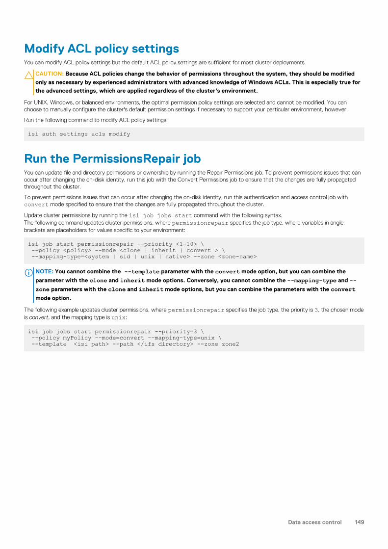
Modify ACL policy settingsYou can modify ACL policy settings but the default ACL policy settings are sufficient for most cluster deployments.
CAUTION: Because ACL policies change the behavior of permissions throughout the system, they should be modified
only as necessary by experienced administrators with advanced knowledge of Windows ACLs. This is especially true for
the advanced settings, which are applied regardless of the cluster's environment.
For UNIX, Windows, or balanced environments, the optimal permission policy settings are selected and cannot be modified. You canchoose to manually configure the cluster's default permission settings if necessary to support your particular environment, however.
Run the following command to modify ACL policy settings:
isi auth settings acls modify
Run the PermissionsRepair jobYou can update file and directory permissions or ownership by running the Repair Permissions job. To prevent permissions issues that canoccur after changing the on-disk identity, run this job with the Convert Permissions job to ensure that the changes are fully propagatedthroughout the cluster.
To prevent permissions issues that can occur after changing the on-disk identity, run this authentication and access control job withconvert mode specified to ensure that the changes are fully propagated throughout the cluster.
Update cluster permissions by running the isi job jobs start command with the following syntax.The following command updates cluster permissions, where permissionrepair specifies the job type, where variables in anglebrackets are placeholders for values specific to your environment:
isi job start permissionrepair --priority <1-10> \ --policy <policy> --mode <clone | inherit | convert > \ --mapping-type=<system | sid | unix | native> --zone <zone-name>
NOTE: You cannot combine the --template parameter with the convert mode option, but you can combine the
parameter with the clone and inherit mode options. Conversely, you cannot combine the --mapping-type and --zone parameters with the clone and inherit mode options, but you can combine the parameters with the convertmode option.
The following example updates cluster permissions, where permissionrepair specifies the job type, the priority is 3, the chosen modeis convert, and the mapping type is unix:
isi job jobs start permissionrepair --priority=3 \ --policy myPolicy --mode=convert --mapping-type=unix \ --template <isi path> --path </ifs directory> --zone zone2
Data access control 149

File sharingThis section contains the following topics:
Topics:
• File sharing overview• SMB• NFS• FTP• HTTP and HTTPS
File sharing overviewMulti-protocol support in OneFS enables files and directories on the Isilon cluster to be accessed through SMB for Windows file sharing,NFS for UNIX file sharing, secure shell (SSH), FTP, and HTTP. By default, only the SMB and NFS protocols are enabled.
OneFS creates the /ifs directory, which is the root directory for all file system data on the cluster. The /ifs directory is configured asan SMB share and an NFS export by default. You can create additional shares and exports within the /ifs directory tree.
NOTE: We recommend that you do not save data to the root /ifs file path but in directories below /ifs. The design of
your data storage structure should be planned carefully. A well-designed directory structure optimizes cluster
performance and administration.
You can set Windows- and UNIX-based permissions on OneFS files and directories. Users who have the required permissions andadministrative privileges can create, modify, and read data on the cluster through one or more of the supported file sharing protocols.
• SMB. Allows Microsoft Windows and Mac OS X clients to access files that are stored on the cluster.• NFS. Allows Linux and UNIX clients that adhere to the RFC1813 (NFSv3) and RFC3530 (NFSv4) specifications to access files that are
stored on the cluster.• HTTP and HTTPS (with optional DAV). Allows clients to access files that are stored on the cluster through a web browser.• FTP. Allows any client that is equipped with an FTP client program to access files that are stored on the cluster through the FTP
protocol.
Mixed protocol environmentsThe /ifs directory is the root directory for all file system data in the cluster, serving as an SMB share, an NFS export, and a documentroot directory. You can create additional shares and exports within the /ifs directory tree. You can configure your OneFS cluster to useSMB or NFS exclusively, or both. You can also enable HTTP, FTP, and SSH.
Access rights are consistently enforced across access protocols on all security models. A user is granted or denied the same rights to a filewhether using SMB or NFS. Clusters running OneFS support a set of global policy settings that enable you to customize the defaultaccess control list (ACL) and UNIX permissions settings.
OneFS is configured with standard UNIX permissions on the file tree. Through Windows Explorer or OneFS administrative tools, you cangive any file or directory an ACL. In addition to Windows domain users and groups, ACLs in OneFS can include local, NIS, and LDAP usersand groups. After a file is given an ACL, the mode bits are no longer enforced and exist only as an estimate of the effective permissions.
NOTE: We recommend that you configure ACL and UNIX permissions only if you fully understand how they interact with
one another.
11
150 File sharing

Write caching with SmartCacheWrite caching accelerates the process of writing data to the cluster. OneFS includes a write-caching feature called SmartChache, which isenabled by default for all files and directories.
If write caching is enabled, OneFS writes data to a write-back cache instead of immediately writing the data to disk. OneFS can write thedata to disk at a time that is more convenient.
NOTE: We recommend that you keep write caching enabled. You should also enable write caching for all file pool
policies.
OneFS interprets writes to the cluster as either synchronous or asynchronous, depending on a client's specifications. The impacts andrisks of write caching depend on what protocols clients use to write to the cluster, and whether the writes are interpreted as synchronousor asynchronous. If you disable write caching, client specifications are ignored and all writes are performed synchronously.
The following table explains how clients' specifications are interpreted, according to the protocol.
Protocol Synchronous Asynchronous
NFS The stable field is set to data_sync orfile_sync.
The stable field is set to unstable.
SMB The write-through flag has beenapplied.
The write-through flag has not beenapplied.
Write caching for asynchronous writesWriting to the cluster asynchronously with write caching is the fastest method of writing data to your cluster.
Write caching for asynchronous writes requires fewer cluster resources than write caching for synchronous writes, and will improveoverall cluster performance for most workflows. However, there is some risk of data loss with asynchronous writes.
The following table describes the risk of data loss for each protocol when write caching for asynchronous writes is enabled:
Protocol Risk
NFS If a node fails, no data will be lost except in the unlikely event thata client of that node also crashes before it can reconnect to thecluster. In that situation, asynchronous writes that have not beencommitted to disk will be lost.
SMB If a node fails, asynchronous writes that have not been committedto disk will be lost.
We recommend that you do not disable write caching, regardless of the protocol that you are writing with. If you are writing to the clusterwith asynchronous writes, and you decide that the risks of data loss are too great, we recommend that you configure your clients to usesynchronous writes, rather than disable write caching.
Write caching for synchronous writesWrite caching for synchronous writes costs cluster resources, including a negligible amount of storage space. Although it is not as fast aswrite caching with asynchronous writes, unless cluster resources are extremely limited, write caching with synchronous writes is fasterthan writing to the cluster without write caching.
Write caching does not affect the integrity of synchronous writes; if a cluster or a node fails, none of the data in the write-back cache forsynchronous writes is lost.
SMBOneFS includes a configurable SMB service to create and manage SMB shares. SMB shares provide Windows clients network access tofile system resources on the cluster. You can grant permissions to users and groups to carry out operations such as reading, writing, andsetting access permissions on SMB shares.
The /ifs directory is configured as an SMB share and is enabled by default. OneFS supports both user and anonymous security modes. Ifthe user security mode is enabled, users who connect to a share from an SMB client must provide a valid user name with propercredentials.
File sharing 151

SMB shares act as checkpoints, and users must have access to a share in order to access objects in a file system on a share. If a user hasaccess granted to a file system, but not to the share on which it resides, that user will not be able to access the file system regardless ofprivileges. For example, assume a share named ABCDocs contains a file named file1.txt in a path such as: /ifs/data/ABCDocs/file1.txt. If a user attempting to access file1.txt does not have share privileges on ABCDocs, that user cannot access the fileeven if originally granted read and/or write privileges to the file.
The SMB protocol uses security identifiers (SIDs) for authorization data. All identities are converted to SIDs during retrieval and areconverted back to their on-disk representation before they are stored on the cluster.
When a file or directory is created, OneFS checks the access control list (ACL) of its parent directory. If the ACL contains any inheritableaccess control entries (ACEs), a new ACL is generated from those ACEs. Otherwise, OneFS creates an ACL from the combined file anddirectory create mask and create mode settings.
OneFS supports the following SMB clients:
SMB version Supported operating systems
3.0 - Multichannel only Windows 8 or later
Windows Server 2012 or later
2.1 Windows 7 or later
Windows Server 2008 R2 or later
2.0 Windows Vista or later
Windows Server 2008 or later
Mac OS X 10.9 or later
1.0 Windows 2000 or later
Windows XP or later
Mac OS X 10.5 or later
SMB shares in access zonesYou can create and manage SMB shares within access zones.
You can create access zones that partition storage on the cluster into multiple virtual containers. Access zones support all configurationsettings for authentication and identity management services on the cluster, so you can configure authentication providers and provisionSMB shares on a zone-by-zone basis. When you create an access zone, a local provider is created automatically, which allows you toconfigure each access zone with a list of local users and groups. You can also authenticate through a different Active Directory provider ineach access zone, and you can control data access by directing incoming connections to the access zone from a specific IP address in apool. Associating an access zone with an IP address pool restricts authentication to the associated access zone and reduces the numberof available and accessible SMB shares.
Here are a few ways to simplify SMB management with access zones:
• Migrate multiple SMB servers, such as Windows file servers or NetApp filers, to a single Isilon cluster, and then configure a separateaccess zone for each SMB server.
• Configure each access zone with a unique set of SMB share names that do not conflict with share names in other access zones, andthen join each access zone to a different Active Directory domain.
• Reduce the number of available and accessible shares to manage by associating an IP address pool with an access zone to restrictauthentication to the zone.
• Configure default SMB share settings that apply to all shares in an access zone.
The cluster includes a built-in access zone named System, where you manage all aspects of the cluster and other access zones. If youdon't specify an access zone when managing SMB shares, OneFS will default to the System zone.
SMB MultichannelSMB Multichannel supports establishing a single SMB session over multiple network connections.
SMB Multichannel is a feature of the SMB 3.0 protocol that provides the following capabilities:
152 File sharing

Increasedthroughput
OneFS can transmit more data to a client through multiple connections over high speed network adapters or overmultiple network adapters.
Connection failuretolerance
When an SMB Multichannel session is established over multiple network connections, the session is not lost if oneof the connections has a network fault, which enables the client to continue to work.
Automaticdiscovery
SMB Multichannel automatically discovers supported hardware configurations on the client that have multipleavailable network paths and then negotiates and establishes a session over multiple network connections. You arenot required to install components, roles, role services, or features.
SMB Multichannel requirementsYou must meet software and NIC configuration requirements to support SMB Multichannel on a cluster.
OneFS can only support SMB Multichannel when the following software requirements are met:
• Windows Server 2012, 2012 R2 or Windows 8, 8.1 clients• SMB Multichannel must be enabled on both the cluster and the Windows client computer. It is enabled on the cluster by default.
SMB Multichannel establishes a single SMB session over multiple network connections only on supported network interface card (NIC)configurations. SMB Multichannel requires at least one of the following NIC configurations on the client computer:
• Two or more network interface cards.• One or more network interface cards that support Receive Side Scaling (RSS).• One or more network interface cards configured with link aggregation. Link aggregation enables you to combine the bandwidth of
multiple NICs on a node into a single logical interface.
Client-side NIC configurations supported by SMB MultichannelSMB Multichannel automatically discovers supported hardware configurations on the client that have multiple available network paths.
Each node on the cluster has at least one RSS-capable network interface card (NIC). Your client-side NIC configuration determines howSMB Multichannel establishes simultaneous network connections per SMB session.
Client-side NICConfiguration
Description
Single RSS-capable NIC SMB Multichannel establishes a maximum of four network connections to the Isilon cluster over the NIC.The connections are more likely to be spread across multiple CPU cores, which reduces the likelihood ofperformance bottleneck issues and achieves the maximum speed capability of the NIC.
Multiple NICs If the NICs are RSS-capable, SMB Multichannel establishes a maximum of four network connections tothe Isilon cluster over each NIC. If the NICs on the client are not RSS-capable, SMB Multichannelestablishes a single network connection to the Isilon cluster over each NIC. Both configurations allowSMB Multichannel to leverage the combined bandwidth of multiple NICs and provides connection faulttolerance if a connection or a NIC fails.
NOTE: SMB Multichannel cannot establish more than eight simultaneous networkconnections per session. In a multiple NIC configuration, this might limit the numberconnections allowed per NIC. For example, if the configuration contains three RSS-capable NICs, SMB Multichannel might establish three connections over the first NIC,three connections over the second NIC and two connections over the third NIC.
Aggregated NICs SMB Multichannel establishes multiple network connections to the Isilon cluster over aggregated NICs,which results in balanced connections across CPU cores, effective consumption of combinedbandwidth, and connection fault tolerance.
NOTE: The aggregated NIC configuration inherently provides NIC fault tolerance that isnot dependent upon SMB.
SMB share management through MMCOneFS supports the Shared Folders snap-in for the Microsoft Management Console (MMC), which allows SMB shares on the cluster tobe managed using the MMC tool.
Typically, you connect to the global System zone through the web administration interface or the command line interface to manage andconfigure shares. If you configure access zones, you can connect to a zone through the MMC Shared Folders snap-in to directly manageall shares in that zone.
File sharing 153

You can establish a connection through the MMC Shared Folders snap-in to an Isilon node and perform the following SMB sharemanagement tasks:
• Create and delete shared folders• Configure access permission to an SMB share• View a list of active SMB sessions• Close open SMB sessions• View a list of open files• Close open files
When you connect to a zone through the MMC Shared Folders snap-in, you can view and manage all SMB shares assigned to that zone;however, you can only view active SMB sessions and open files on the specific node that you are connected to in that zone. Changes youmake to shares through the MMC Shared Folders snap-in are propagated across the cluster.
MMC connection requirementsYou can connect to a cluster through the MMC Shared Folders snap-in if you meet access requirements.
The following conditions are required to establish a connection through the MMC Shared Folders snap-in:
• You must run the Microsoft Management Console (MMC) from a Windows workstation that is joined to the domain of an ActiveDirectory (AD) provider configured on the cluster.
• You must be a member of the local <cluster>\Administrators group.NOTE: Role-based access control (RBAC) privileges do not apply to the MMC. A role with SMB privileges is not
sufficient to gain access.
• You must log in to a Windows workstation as an Active Directory user that is a member of the local <cluster>\Administrators group.
SMBv3 encryptionCertain Microsoft Windows and Apple Mac client/server combinations can support data encryption in SMBv3 environments.
You can configure SMBv3 encryption on a per-share, per-zone, or cluster-wide basis. You can allow encrypted and unencrypted clientsaccess. Globally and for access zones, you can also require that all client connections are encrypted.
If you set encryption settings on a per-zone basis, those settings will override global server settings.
NOTE: Per-zone and per-share encryption settings can only be configured through the OneFS command line interface.
Enable SMBv3 encryption for an SMB shareYou can enable or disable SMBv3 encryption on a share.
To enable SMBv3 encryption for an share:
• isi smb settings shares modify --support-smb3-encryption yesSMBv3 encryption is enabled. To disable SMBv3 encryption, use the --revert-support-smb3-encryption option.
Enable SMBv3 encryption for an access zoneYou can enable SMBv3 encryption on a per access zone basis. Zone-specific encryption settings override global encryption settings.
To enable SMBv3 encryption for an access zone:
• isi smb settings zone modify --zone=<zone> --support-smb3-encryption yesSMBv3 encryption is enabled for the specific access zone. To disable SMBv3 encryption, use the --revert-support-smb3-encryption option.
Enable SMBv3 encryption globallyYou can enable SMBv3 encryption on a global basis. However, if you later set or modify encryption settings on an access zone level, thosesettings will override the global settings.
To enable SMBv3 encryption globally:
• isi smb settings global modify --support-smb3-encryption yesSMBv3 encryption is enabled globally on the cluster. To disable SMBv3 encryption, use the --revert-support-smb3-encryption option.
154 File sharing

Enforce SMBv3 encryptionYou can require that all client connections to a cluster or access zone are encrypted for SMBv3.
For example, to require that all connections to an access zone are encrypted:
• isi smb settings zone modify --zone=<zone> --reject-unencrypted-access yesSMBv3 encryption is required for a client to connect to the specific access zone. To disable SMBv3 encryption requirement, use the--revert-reject-unencrypted access option.
SMB server-side copyIn order to increase system performance, SMB 2 and later clients can utilize the server-side copy feature in OneFS.
Windows clients making use of server-side copy support may experience performance improvements for file copy operations, because filedata no longer needs to traverse the network. The server-side copy feature reads and writes files only on the server, avoiding the networkround-trip and duplication of file data. This feature only affects file copy or partial copy operations in which the source and destination filehandles are open on the same share, and does not work for cross-share operations.
This feature is enabled by default across OneFS clusters, and can only be disabled system-wide across all zones. Additionally, server-sidecopy in OneFS is incompatible with the SMB continuous availability feature. If continuous availability is enabled for a share and the clientopens a persistent file handle, server-side copy is automatically disabled for that file.
NOTE: You can only disable or enable SMB server-side copy for OneFS using the command line interface (CLI).
Enable or disable SMB server-side copyYou can enable or disable the SMB server-side copy feature.
The SMB server-side copy feature is enabled in OneFS by default.
1. Open a secure shell (SSH) connection to the cluster.2. Run the isi smb settings global modify command.
3. Modify the --server-side-copy option as necessary.
This feature is enabled by default.
For example, the following command disables SMB server-side copy:
isi smb settings global modify --server-side-copy=no
SMB continuous availabilityIf you are running OneFS in an SMB 3.0 environment, you allow certain Windows clients to open files on a server with continuousavailability enabled.
If a server is using Windows 8 or Windows Server 2012, clients can create persistent file handles that can be reclaimed after an outagesuch as a network-related disconnection or a server failure. You can specify how long the persistent handle is retained after adisconnection or server failure, and also force strict lockouts on users attempting to open a file belonging to another handle. Furthermore,through the OneFS command-line interface (CLI), you can configure write integrity settings to control the stability of writes to the share.
If continuous availability is enabled for a share and the client opens a persistent file handle, server-side copy is automatically disabled forthat file.
NOTE: You can only enable continuous availability when creating a share, but you can update timeout, lockout, and write
integrity settings when creating or modifying a share.
Enable SMB continuous availabilityYou can enable SMB 3.0 continuous availability and configure settings when you create a share.
You can also update continuous availability timeout, lockout, and write integrity settings when you modify a share.
• Run isi smb shares create to enable this feature and configure settings, and isi smb shares modify or isi smbsettings shares modify to change settings.
File sharing 155

The following command enables continuous availability on a new share named Share4, sets the timeout for the handle to three minutes(180 seconds), enforces a strict lockout, and changes the write integrity setting to full:
isi smb shares create --name=Share4 --path=/ifs/data/Share4 \--continuously-available=yes --ca-timeout=180 \--strict-ca-lockout=yes --ca-write-integrity=full
SMB file filteringYou can use SMB file filtering to allow or deny file writes to a share or access zone.
This feature enables you to deny certain types of files that might cause throughput issues, security problems, storage clutter, orproductivity disruptions. You can restrict writes by allowing writes of certain file types to a share.
• If you choose to deny file writes, you can specify file types by extension that are not allowed to be written. OneFS permits all other filetypes to be written to the share.
• If you choose to allow file writes, you can specify file types by extension that are allowed to be written. OneFS denies all other filetypes to be written to the share.
You can add or remove file extensions if your restriction policies change.
Enable SMB file filteringYou can enable or disable SMB file filtering when you create or modify a share.
• Run isi smb shares create or isi smb shares modify.The following command enables file filtering on a share named Share2 and denies writes by the file types .wav and .mpg:
isi smb shares modify Share2 --file-filtering-enabled=yes \file-filter-extensions=.wav,.mpg
The following command enables file filtering on a share named Share3, specifies the file type .xml, and specifies to allow writes forthat file type:
isi smb shares modify Share3 --file-filtering-enabled=yes \file-filter-extensions=.xml --file-filter-type=allow
Symbolic links and SMB clientsOneFS enables SMB2 clients to access symbolic links in a seamless manner. Many administrators deploy symbolic links to virtually reorderfile system hierarchies, especially when crucial files or directories are scattered around an environment.
In an SMB share, a symbolic link (also known as a symlink or a soft link) is a type of file that contains a path to a target file or directory.Symbolic links are transparent to applications running on SMB clients, and they function as typical files and directories. Support for relativeand absolute links is enabled by the SMB client. The specific configuration depends on the client type and version.
A symbolic link that points to a network file or directory that is not in the path of the active SMB session is referred to as an absolute (orremote) link. Absolute links always point to the same location on a file system, regardless of the present working directory, and usuallycontain the root directory as part of the path. Conversely, a relative link is a symbolic link that points directly to a user's or application'sworking directory, so you do not have to specify the full absolute path when creating the link.
OneFS exposes symbolic links through the SMB2 protocol, enabling SMB2 clients to resolve the links instead of relying on OneFS toresolve the links on behalf of the clients. To transverse a relative or absolute link, the SMB client must be authenticated to the SMBshares that the link can be followed through. However, if the SMB client does not have permission to access the share, access to thetarget is denied and Windows will not prompt the user for credentials.
SMB2 and NFS links are interoperable for relative links only. For maximum compatibility, create these links from a POSIX client.
NOTE: SMB1 clients (such as Windows XP or 2002) may still use relative links, but they are traversed on the server side
and referred to as "shortcut files." Absolute links do not work in these environments.
156 File sharing

Enabling symbolic linksBefore you can fully use symbolic links in an SMB environment, you must enable them.
For Windows SMB clients to traverse each type of symbolic link, you must enable them on the client. Windows supports the following linktypes:
• local to local• remote to remote• local to remote• remote to local
You must run the following Windows command to enable all four link types:
fsutil behavior set SymlinkEvaluation L2L:1 R2R:1 L2R:1 R2L:1
For POSIX clients using Samba, you must set the following options in the [global] section of your Samba configuration file(smb.conf) to enable Samba clients to traverse relative and absolute links:
follow symlinks=yes wide links=yes
In this case, "wide links" in the smb.conf file refers to absolute links. The default setting in this file is no.
Managing symbolic linksAfter enabling symbolic links, you can create or delete them from the Windows command prompt or a POSIX command line.
Create symbolic links using the Windows mklink command on an SMB2 client or the ln command from a POSIX command-lineinterface. For example, an administrator may want to give a user named User1 access to a file named File1.doc in the /ifs/data/directory without giving specific access to that directory by creating a link named Link1:
mklink \ifs\home\users\User1\Link1 \ifs\data\Share1\File1.doc
When you create a symbolic link, it is designated as a file link or directory link. Once the link is set, the designation cannot be changed. Youcan format symbolic link paths as either relative or absolute.
To delete symbolic links, use the del command in Windows, or the rm command in a POSIX environment.
Keep in mind that when you delete a symbolic link, the target file or directory still exists. However, when you delete a target file ordirectory, a symbolic link continues to exist and still points to the old target, thus becoming a broken link.
Anonymous access to SMB sharesYou can configure anonymous access to SMB shares by enabling the local Guest user and allowing impersonation of the guest user.
For example, if you store files such as browser executables or other data that is public on the internet, anonymous access allows any userto access the SMB share without authenticating.
Managing SMB settingsYou can enable or disable the SMB service, configure global settings for the SMB service, and configure default SMB share settings thatare specific to each access zone.
View global SMB settingsYou can view the global SMB settings that are applied to all nodes on the cluster. This task can only be performed through the OneFScommand-line interface.
1. Establish an SSH connection to any node in the cluster.2. Run the isi smb settings global view command.
The system displays output similar to the following example:
Access Based Share Enum: No Dot Snap Accessible Child: Yes Dot Snap Accessible Root: Yes Dot Snap Visible Child: No
File sharing 157
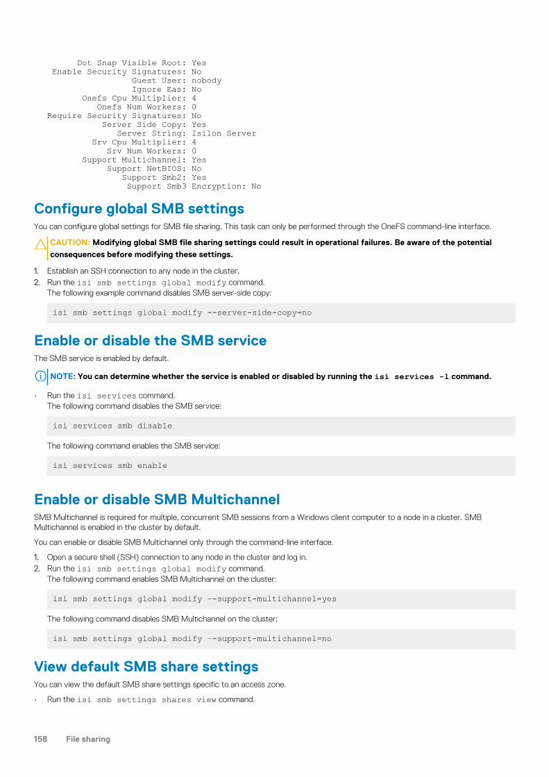
Dot Snap Visible Root: Yes Enable Security Signatures: No Guest User: nobody Ignore Eas: No Onefs Cpu Multiplier: 4 Onefs Num Workers: 0Require Security Signatures: No Server Side Copy: Yes Server String: Isilon Server Srv Cpu Multiplier: 4 Srv Num Workers: 0 Support Multichannel: Yes Support NetBIOS: No Support Smb2: Yes Support Smb3 Encryption: No
Configure global SMB settingsYou can configure global settings for SMB file sharing. This task can only be performed through the OneFS command-line interface.
CAUTION: Modifying global SMB file sharing settings could result in operational failures. Be aware of the potential
consequences before modifying these settings.
1. Establish an SSH connection to any node in the cluster.2. Run the isi smb settings global modify command.
The following example command disables SMB server-side copy:
isi smb settings global modify --server-side-copy=no
Enable or disable the SMB serviceThe SMB service is enabled by default.
NOTE: You can determine whether the service is enabled or disabled by running the isi services -l command.
• Run the isi services command.The following command disables the SMB service:
isi services smb disable
The following command enables the SMB service:
isi services smb enable
Enable or disable SMB MultichannelSMB Multichannel is required for multiple, concurrent SMB sessions from a Windows client computer to a node in a cluster. SMBMultichannel is enabled in the cluster by default.
You can enable or disable SMB Multichannel only through the command-line interface.
1. Open a secure shell (SSH) connection to any node in the cluster and log in.2. Run the isi smb settings global modify command.
The following command enables SMB Multichannel on the cluster:
isi smb settings global modify –-support-multichannel=yes
The following command disables SMB Multichannel on the cluster:
isi smb settings global modify –-support-multichannel=no
View default SMB share settingsYou can view the default SMB share settings specific to an access zone.
• Run the isi smb settings shares view command.
158 File sharing

The following example command displays the default SMB share settings configured for zone5 :
isi smb settings shares view --zone=zone5
The system displays output similar to the following example:
Access Based Enumeration: NoAccess Based Enumeration Root Only: No Allow Delete Readonly: No Allow Execute Always: No Ca Timeout: 120 Strict Ca Lockout: No Change Notify: norecurse Create Permissions: default acl Directory Create Mask: 0700 Directory Create Mode: 0000 File Create Mask: 0700 File Create Mode: 0100 File Filtering Enabled: Yes File Filter Extensions: .wav File Filter Type: deny Hide Dot Files: No Host ACL: - Impersonate Guest: never Impersonate User: - Mangle Byte Start: 0XED00 Mangle Map: 0x01-0x1F:-1, 0x22:-1, 0x2A:-1, 0x3A:-1, 0x3C:-1, 0x3E:-1, 0x3F:-1, 0x5C:-1 Ntfs ACL Support: Yes Oplocks: Yes Strict Flush: Yes Strict Locking: No
Configure default SMB share settingsYou can configure SMB share settings specific to each access zone.
The default settings are applied to all new shares that are added to the access zone.
CAUTION: If you modify the default settings, the changes are applied to all existing shares in the access zone.
Run the isi smb settings shares modify command.The following command specifies that guests are never allowed access to shares in zone5:
isi smb settings global modify --zone=zone5 --impersonate-guest=never
Managing SMB sharesYou can configure the rules and other settings that govern the interaction between your Windows network and individual SMB shares onthe cluster.
OneFS supports %U, %D, %Z, %L, %0, %1, %2, and %3 variable expansion and automatic provisioning of user home directories.
You can configure the users and groups that are associated with an SMB share, and view or modify their share-level permissions.
NOTE: We recommend that you configure advanced SMB share settings only if you have a solid understanding of the
SMB protocol.
Create an SMB shareWhen you create an SMB share, you can override the default permissions, performance, and access settings. You can configure SMBhome directory provisioning by including expansion variables in the share path to automatically create and redirect users to their ownhome directories.
You must specify a path to use as the SMB share. Shares are specific to access zones and the share path must exist under the zone path.You can specify an existing path or create the path at the time you create the share. Create access zones before you create SMB shares.
File sharing 159

You can specify one or more expansion variables in the directory path but you must set the flags to true for both the --allow-variable-expansion and --auto-create-directory parameters. If you do not specify these settings, the variable expansionstring is interpreted literally by the system.
1. Run the isi smb shares create command.The following commands creates a directory at /ifs/zone5/data/share1, creates a share named share1 using that path, andadds the share to the existing access zone named zone5:
mkdir /ifs/data/share1 isi smb shares create --name=share1 \--path=/ifs/data/share1 --zone=zone5 --browsable=true \--description="Example Share 1"
NOTE: Share names can contain up to 80 characters, except for the following: " \ / [ ] : | < > + = ; , * ?
Also, if the cluster character encoding is not set to UTF-8, SMB share names are case-sensitive.
The following command creates a directory at /ifs/data/share2, converts it to an SMB share, and adds the share to the defaultSystem zone because no zone is specified:
isi smb shares create share2 --path=/ifs/data/share2 \--create-path --browsable=true --description="Example Share 2"
The following command creates a directory at /ifs/data/share3 and converts it to an SMB share. The command also applies anACL to the share:
isi smb shares create share3 --path=/ifs/data/share3 \--create-path --browsable=true --description="Example Share 3" \ --inheritable-path-acl=true --create-permissions="default acl"
NOTE: If no default ACL is configured and the parent directory does not have an inheritable ACL, an ACL is created
for the share with the directory-create-mask and directory-create-mode settings.
The following command creates the directory /ifs/data/share4 and converts it to a non-browsable SMB share. The commandalso configures the use of mode bits for permissions control:
isi smb shares create --name=share4 --path=/ifs/data/share4 \--create-path --browsable=false --description="Example Share 4" \--inheritable-path-acl=true --create-permissions="use create \mask and mode"
2. The following command creates home directories for each user that connects to the share, based on the user's NetBIOS domain anduser name.In this example, if a user is in a domain named DOMAIN and has a username of user_1, the path /ifs/home/%D/%U expandsto /ifs/home/DOMAIN/user_1.
isi smb shares modify HOMEDIR --path=/ifs/home/%D/%U \--allow-variable-expansion=yes --auto-create-directory=yes
The following command creates a share named HOMEDIR with the existing path /ifs/share/home:
isi smb shares create HOMEDIR /ifs/share/home3. Run the isi smb shares permission modify command to enable access to the share.
The following command allows the well-known user Everyone full permissions to the HOMEDIR share:
isi smb shares permission modify HOMEDIR --wellknown Everyone \ --permission-type allow --permission full
Modify an SMB shareYou can modify the settings of individual SMB shares.
SMB shares are zone-specific. When you modify a share, you must identify the access zone that the share belongs to. If you do notidentify the access zone, OneFS defaults to the System zone. If the share you want to modify has the same name as a share in theSystem zone, the share in the System zone is modified.
Run the isi smb shares modify command.
160 File sharing

In the following example, the file path for share1 in zone5 points to /ifs/zone5/data. The following commands modifies the file pathof share1 to /ifs/zone5/etc, which is another directory in the zone5 path:
isi smb shares modify share1 --zone=zone5 \ --path=/ifs/zone5/etc
NOTE: If the cluster character encoding is not set to UTF-8, SMB share names are case-sensitive.
Delete an SMB shareYou can delete SMB shares that are no longer needed.
SMB shares are zone-specific. When you delete a share, you must identify the access zone that the share belongs to. If you do notidentify the access zone, OneFS defaults to the System zone. If the share you want to delete has the same name as a share in the Systemzone, the share in the System zone is deleted.
If you delete an SMB share, the share path is deleted but the directory it referenced still exists. If you create a new share with the samepath as the share that was deleted, the directory that the previous share referenced will be accessible again through the new share.
1. Run the isi smb shares delete command.The following command deletes a share named Share1 from the access zone named zone-5:
isi smb shares delete Share1 --zone=zone-52. Type yes at the confirmation prompt.
Limit access to /ifs share for the Everyone accountBy default, the /ifs root directory is configured as an SMB share in the System access zone. It is recommended that you restrict theEveryone account of this share to read-only access.
1. Run the isi smb shares permission modify command.
The following example changes the Everyone account permissions to read-only on the SMB share configured for the /ifs directory:
isi smb shares permission modify ifs --wellknown=Everyone \ -d allow -p read
2. Optional: Verify the change by running the following command to list permissions on the share:
isi smb shares permission list ifs
Configure anonymous access to a single SMB shareYou can configure anonymous access to data stored on a single share through Guest user impersonation.
1. Enable the Guest user account in the access zone that contains the share you want by running the isi auth users modifycommand.The following command enables the guest user in the access zone named zone3:
isi auth users modify Guest --enabled=yes --zone=zone32. Set guest impersonation on the share you want to allow anonymous access to by running the isi smb share modify command.
The following command configures guest impersonation on a share named share1 in zone3:
isi smb share modify share1 --zone=zone3 \--impersonate-guest=always
3. Verify that the Guest user account has permission to access the share by running the isi smb share permission listcommand.The following command list the permissions for share1 in zone3:
isi smb share permission list share1 --zone=zone3
The system displays output similar to the following example
File sharing 161

Account Account Type Run as Root Permission Type Permission----------------------------------------------------------------Everyone wellknown False allow readGuest user False allow full----------------------------------------------------------------
Configure anonymous access to all SMB shares in an access zoneYou can configure anonymous access to data stored in an access zone through Guest user impersonation.
1. Enable the Guest user account in the access zone that contains the share you want by running the isi auth users modifycommand.The following command enables the guest user in the access zone named zone3:
isi auth users modify Guest --enabled=yes --zone=zone32. Set guest impersonation as the default value for all shares in the access zone by running the isi smb settings share modify
command.The following command configures guest impersonation for all shares in zone3:
isi smb settings share modify --zone=zone3 \--impersonate-guest=always
3. Verify that the Guest user account has permission to each share in the access zone by running the isi smb share permissionlist command.The following command list the permissions for share1 in zone3:
isi smb share permission list share1 --zone=zone3
The system displays output similar to the following example
Account Account Type Run as Root Permission Type Permission----------------------------------------------------------------Everyone wellknown False allow readGuest user False allow full----------------------------------------------------------------
Configure multi-protocol home directory accessFor users who will access this share through FTP or SSH, you can make sure that their home directory path is the same whether theyconnect through SMB or they log in through FTP or SSH. This task may only be performed at the OneFS command-line interface.
This command directs the SMB share to use the home directory template that is specified in the user's authentication provider. Thisprocedure is available only through the command-line interface.
1. Establish an SSH connection to any node in the cluster.2. Run the following command, where <share> is the name of the SMB share and --path is the directory path of the home directory
template specified by the user's authentication provider:
isi smb shares modify <share> --path=""
Supported expansion variablesYou can include expansion variables in an SMB share path or in an authentication provider's home directory template.
OneFS supports the following expansion variables. You can improve performance and reduce the number of shares to be managed whenyou configure shares with expansion variables. For example, you can include the %U variable for a share rather than create a share foreach user. When a %U is included in the name so that each user's path is different, security is still ensured because each user can viewand access only his or her home directory.
NOTE: When you create an SMB share through the web administration interface, you must select the Allow Variable
Expansion check box or the string is interpreted literally by the system.
Variable Value Description
%U User name (for example,user_001)
Expands to the user name to allow different users to use differenthome directories. This variable is typically included at the end of
162 File sharing

Variable Value Description
the path. For example, for a user named user1, the path /ifs/home/%U is mapped to /ifs/home/user1.
%D NetBIOS domain name (forexample, YORK forYORK.EAST.EXAMPLE.COM)
Expands to the user's domain name, based on the authenticationprovider:
• For Active Directory users, %D expands to the Active DirectoryNetBIOS name.
• For local users, %D expands to the cluster name in uppercasecharacters. For example, for a cluster named cluster1, %Dexpands to CLUSTER1.
• For users in the System file provider, %D expands toUNIX_USERS.
• For users in other file providers, %D expands to FILE_USERS.• For LDAP users, %D expands to LDAP_USERS.• For NIS users, %D expands to NIS_USERS.
%Z Zone name (for example,ZoneABC)
Expands to the access zone name. If multiple zones are activated,this variable is useful for differentiating users in separate zones.For example, for a user named user1 in the System zone, thepath /ifs/home/%Z/%U is mapped to /ifs/home/System/user1.
%L Host name (cluster host namein lowercase)
Expands to the host name of the cluster, normalized to lowercase.Limited use.
%0 First character of the user name Expands to the first character of the user name.
%1 Second character of the username
Expands to the second character of the user name.
%2 Third character of the username
Expands to the third character of the user name.
NOTE: If the user name includes fewer than three characters, the %0, %1, and %2 variables wrap around. For example,
for a user named ab, the variables maps to a, b, and a, respectively. For a user named a, all three variables map to a.
NFSOneFS provides an NFS server so you can share files on your cluster with NFS clients that adhere to the RFC1813 (NFSv3) and RFC3530(NFSv4) specifications.
In OneFS, the NFS server is fully optimized as a multi-threaded service running in user space instead of the kernel. This architecture loadbalances the NFS service across all nodes of the cluster, providing the stability and scalability necessary to manage up to thousands ofconnections across multiple NFS clients.
NFS mounts execute and refresh quickly, and the server constantly monitors fluctuating demands on NFS services and makesadjustments across all nodes to ensure continuous, reliable performance. Using a built-in process scheduler, OneFS helps ensure fairallocation of node resources so that no client can seize more than its fair share of NFS services.
The NFS server also supports access zones defined in OneFS, so that clients can access only the exports appropriate to their zone. Forexample, if NFS exports are specified for Zone 2, only clients assigned to Zone 2 can access these exports.
To simplify client connections, especially for exports with large path names, the NFS server also supports aliases, which are shortcuts tomount points that clients can specify directly.
For secure NFS file sharing, OneFS supports NIS and LDAP authentication providers.
NFS exportsYou can manage individual NFS export rules that define mount-points (paths) available to NFS clients and how the server should performwith these clients.
In OneFS, you can create, delete, list, view, modify, and reload NFS exports.
File sharing 163

NFS export rules are zone-aware. Each export is associated with a zone, can only be mounted by clients on that zone, and can onlyexpose paths below the zone root. By default, any export command applies to the client's current zone.
Each rule must have at least one path (mount-point), and can include additional paths. You can also specify that all subdirectories of thegiven path or paths are mountable. Otherwise, only the specified paths are exported, and child directories are not mountable.
An export rule can specify a particular set of clients, enabling you to restrict access to certain mount-points or to apply a unique set ofoptions to these clients. If the rule does not specify any clients, then the rule applies to all clients that connect to the server. If the ruledoes specify clients, then that rule is applied only to those clients.
NFS aliasesYou can create and manage aliases as shortcuts for directory path names in OneFS. If those path names are defined as NFS exports, NFSclients can specify the aliases as NFS mount points.
NFS aliases are designed to give functional parity with SMB share names within the context of NFS. Each alias maps a unique name to apath on the file system. NFS clients can then use the alias name in place of the path when mounting.
Aliases must be formed as top-level Unix path names, having a single forward slash followed by name. For example, you could create analias named /q4 that maps to /ifs/data/finance/accounting/winter2015 (a path in OneFS). An NFS client could mount thatdirectory through either of:
mount cluster_ip:/q4
mount cluster_ip:/ifs/data/finance/accounting/winter2015
Aliases and exports are completely independent. You can create an alias without associating it with an NFS export. Similarly, an NFSexport does not require an alias.
Each alias must point to a valid path on the file system. While this path is absolute, it must point to a location beneath the zone root (/ifson the System zone). If the alias points to a path that does not exist on the file system, any client trying to mount the alias would bedenied in the same way as attempting to mount an invalid full pathname.
NFS aliases are zone-aware. By default, an alias applies to the client's current access zone. To change this, you can specify an alternativeaccess zone as part of creating or modifying an alias.
Each alias can only be used by clients on that zone, and can only apply to paths below the zone root. Alias names are unique per zone, butthe same name can be used in different zones—for example, /home.
When you create an alias in the web administration interface, the alias list displays the status of the alias. Similarly, using the --checkoption of the isi nfs aliases command, you can check the status of an NFS alias (status can be: good, illegal path, name conflict,not exported, or path not found).
NFS log filesOneFS writes log messages associated with NFS events to a set of files in /var/log.
With the log level option, you can now specify the detail at which log messages are output to log files. The following table describes thelog files associated with NFS.
Log file Description
nfs.log Primary NFS server functionality (v3, v4, mount)
rpc_lockd.log NFS v3 locking events through the NLM protocol
rpc_statd.log NFS v3 reboot detection through the NSM protocol
isi_netgroup_d.log Netgroup resolution and caching
Managing the NFS serviceYou can enable or disable the NFS service and specify the NFS versions to support, including NFSv3 and NFSv4. NFS settings are appliedacross all nodes in the cluster.
NOTE: NFSv4 can be enabled non-disruptively on a OneFS cluster, and it will run concurrently with NFSv3. Any existing
NFSv3 clients will not be impacted by enabling NFSv4.
164 File sharing

View NFS settingsYou can view the global NFS settings that are applied to all nodes in the cluster.
• Run the isi nfs settings global view command.The system displays output similar to the following example:
NFSv3 Enabled: Yes NFSv4 Enabled: No NFS Service Enabled: Yes
Configure NFS file sharingYou can enable or disable the NFS service, and set the lock protection level and security type. These settings are applied across all nodesin the cluster. You can change the settings for individual NFS exports that you define.
• Run the isi nfs settings global modify command.The following command enables NFSv4 support:
isi nfs settings global modify --nfsv4-enabled=yes
Enable or disable the NFS serviceIn OneFS, the NFSv3 service is enabled by default. You can also enable NFSv4.
NOTE: You can determine whether NFS services are enabled or disabled by running the isi nfs settings globalview command.
• Run the isi nfs settings global modify command.The following command disables the NFSv3 service:
isi nfs settings global modify --nfsv3-enabled=no
The following command enables the NFSv4 service:
isi nfs settings global modify --nfsv4-enabled=yes
Managing NFS exportsYou can create NFS exports, view and modify export settings, and delete exports that are no longer needed.
The /ifs directory is the top-level directory for data storage in OneFS, and is also the path defined in the default export. By default,the /ifs export disallows root access, but allows other UNIX clients to mount this directory and any subdirectories beneath it.
NOTE: We recommend that you modify the default export to limit access only to trusted clients, or to restrict access
completely. To help ensure that sensitive data is not compromised, other exports that you create should be lower in the
OneFS file hierarchy, and can be protected by access zones or limited to specific clients with either root, read-write, or
read-only access, as appropriate.
Configure default NFS export settingsThe default NFS export settings are applied to new NFS exports. You can override these settings when you create or modify an export.
You can view the current default export settings by running the isi nfs settings export view command.
CAUTION: We recommend that you not modify default export settings unless you are sure of the result.
• Run the isi nfs settings export modify command.The following command specifies a maximum export file size of one terabyte:
isi nfs settings export modify --max-file-size 1099511627776
File sharing 165

The following command restores the maximum export file size to the system default:
isi nfs settings export modify --revert-max-file-size
Create a root-squashing rule for an exportBy default, the NFS service implements a root-squashing rule for the default NFS export. This prevents root users on NFS clients fromexercising root privileges on the NFS server.
In OneFS, the default NFS export is /ifs, the top-level directory where cluster data is stored.
1. Use the isi nfs exports view command to view the current settings of the default export.The following command displays the settings of the default export:
isi nfs exports view 12. Confirm the following default values for these settings, which show that root is mapped to nobody, thereby restricting root access:
Map Root Enabled: True User: Nobody Primary Group: -Secondary Groups: -
3. If the root-squashing rule, for some reason, is not in effect, you can implement it for the default NFS export by running the isi nfsexport modify command, as follows:
isi nfs exports modify 1 --map-root-enabled true --map-root nobody
With these settings, regardless of the users' credentials on the NFS client, they would not be able to gain root privileges on the NFSserver.
Create an NFS exportYou can create NFS exports to share files in OneFS with UNIX-based clients.
Each directory path that you designate for an export must already exist in the /ifs directory tree. A directory path can be used by morethan one export, provided those exports do not have any of the same explicit clients.
The NFS service runs in user space and distributes the load across all nodes in the cluster. This enables the service to be highly scalableand support thousands of exports. As a best practice, however, you should avoid creating a separate export for each client on yournetwork. It is more efficient to create fewer exports, and to use access zones and user mapping to control access.
NOTE: The default security flavor (UNIX) relies upon having a trusted network. If you do not completely trust
everything on your network, create the NFS export with Kerberos using the isi nfs exports create command's
[--security-flavors (unix | krb5 | krb5i | krb5p)] option. If the system does not support Kerberos, it will
not be fully protected because NFS without Kerberos trusts everything on the network and sends all packets in
cleartext. If you cannot use Kerberos, you should find another way to protect the Internet connection. At a minimum, do
the following:
• Limit root access to the cluster to trusted host IP addresses.
• Make sure that all new devices that you add to the network are trusted. Methods for ensuring trust include, but are
not limited to, the following:
○ Use an IPsec tunnel. This option is very secure because it authenticates the devices using secure keys.
○ Configure all of the switch ports to go inactive if they are physically disconnected. In addition, make sure that the
switch ports are MAC limited.
1. Run the isi nfs exports create command.The following command creates an export supporting client access to multiple paths and their subdirectories:
isi nfs exports create /ifs/data/projects,/ifs/home --all-dirs=yes2. Optional: To view the export ID, which is required for modifying or deleting the export, run the isi nfs exports list command.
166 File sharing

Check NFS exports for errorsYou can check for errors in NFS exports, such as conflicting export rules, invalid paths, and unresolvable hostnames and netgroups. Thistask may be performed only through the OneFS command-line interface.
1. Establish an SSH connection to any node in the cluster.2. Run the isi nfs exports check command.
In the following example output, no errors were found:
ID Message--------------------Total: 0In the following example output, export 1 contains a directory path that does not currently exist:
ID Message-----------------------------------1 '/ifs/test' does not exist-----------------------------------Total: 1
Modify an NFS exportYou can modify the settings for an existing NFS export.
CAUTION: Changing export settings may cause performance issues. Make sure you understand the potential impact of
any settings alterations prior to committing any changes.
Run the isi nfs exports modify command.For example, the following adds a client with read-write access to NFS export 2:
isi nfs exports modify 2 --add-read-write-clients 10.1.249.137
This command would override the export's access-restriction setting if there was a conflict. For example, if the export was created withread-write access disabled, the client, 10.1.249.137, would still have read-write permissions on the export.
Delete an NFS exportYou can delete unneeded NFS exports. Any current NFS client connections to these exports become invalid.
You need the export ID number to delete the export. Run the isi nfs exports list command to display a list of exports and theirID numbers.
1. Run the isi nfs exports delete command.In the following example, the command deletes an export whose ID is 2:
isi nfs exports delete 2
In the following example, isi nfs exports delete deletes an export whose ID is 3 without displaying a confirmation prompt. Becareful when using the --force option.
isi nfs exports delete 3 --force2. If you did not specify the --force option, type yes at the confirmation prompt.
Managing NFS aliasesYou can create NFS aliases to simplify exports that clients connect to. An NFS alias maps an absolute directory path to a simple directorypath.
For example, suppose you created an NFS export to /ifs/data/hq/home/archive/first-quarter/finance. You could createthe alias /finance1 to map to that directory path.
NFS aliases can be created in any access zone, including the System zone.
File sharing 167
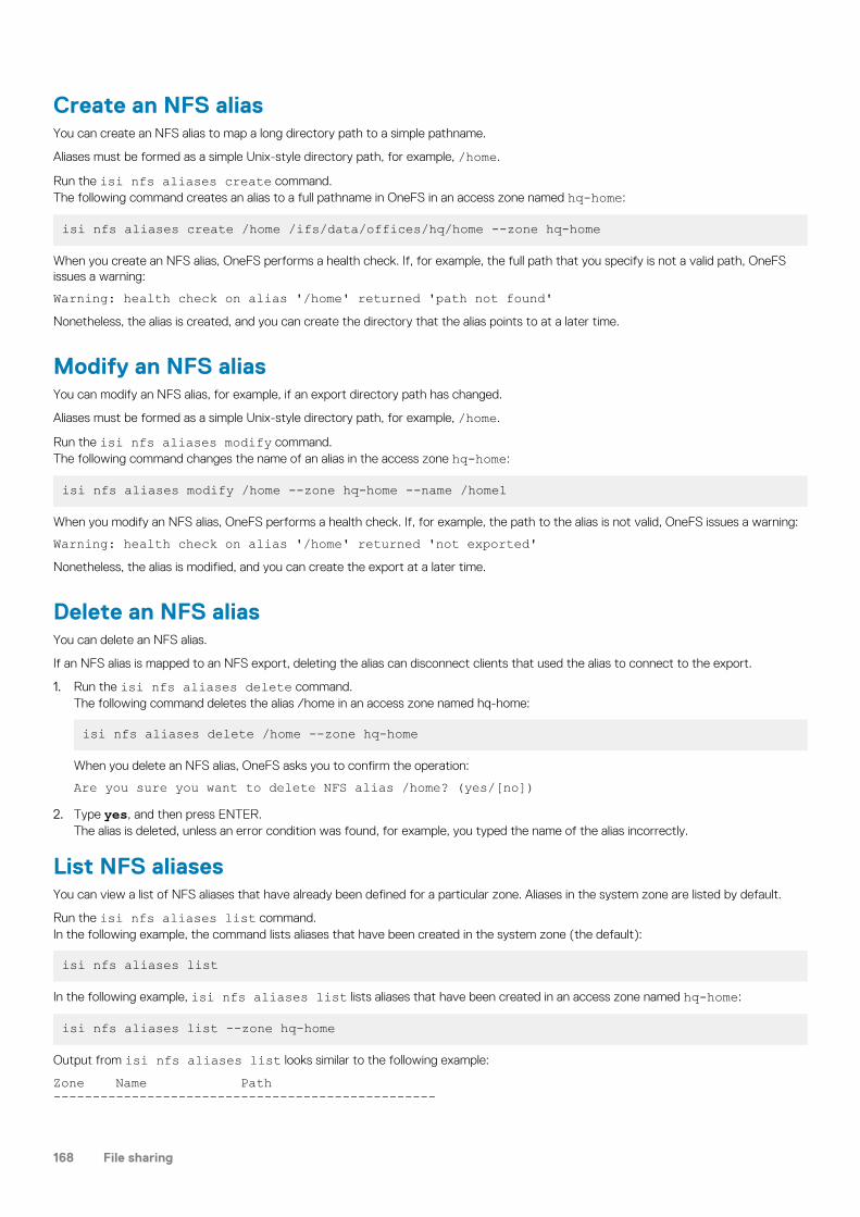
Create an NFS aliasYou can create an NFS alias to map a long directory path to a simple pathname.
Aliases must be formed as a simple Unix-style directory path, for example, /home.
Run the isi nfs aliases create command.The following command creates an alias to a full pathname in OneFS in an access zone named hq-home:
isi nfs aliases create /home /ifs/data/offices/hq/home --zone hq-home
When you create an NFS alias, OneFS performs a health check. If, for example, the full path that you specify is not a valid path, OneFSissues a warning:
Warning: health check on alias '/home' returned 'path not found'Nonetheless, the alias is created, and you can create the directory that the alias points to at a later time.
Modify an NFS aliasYou can modify an NFS alias, for example, if an export directory path has changed.
Aliases must be formed as a simple Unix-style directory path, for example, /home.
Run the isi nfs aliases modify command.The following command changes the name of an alias in the access zone hq-home:
isi nfs aliases modify /home --zone hq-home --name /home1
When you modify an NFS alias, OneFS performs a health check. If, for example, the path to the alias is not valid, OneFS issues a warning:
Warning: health check on alias '/home' returned 'not exported'Nonetheless, the alias is modified, and you can create the export at a later time.
Delete an NFS aliasYou can delete an NFS alias.
If an NFS alias is mapped to an NFS export, deleting the alias can disconnect clients that used the alias to connect to the export.
1. Run the isi nfs aliases delete command.The following command deletes the alias /home in an access zone named hq-home:
isi nfs aliases delete /home --zone hq-home
When you delete an NFS alias, OneFS asks you to confirm the operation:
Are you sure you want to delete NFS alias /home? (yes/[no])2. Type yes, and then press ENTER.
The alias is deleted, unless an error condition was found, for example, you typed the name of the alias incorrectly.
List NFS aliasesYou can view a list of NFS aliases that have already been defined for a particular zone. Aliases in the system zone are listed by default.
Run the isi nfs aliases list command.In the following example, the command lists aliases that have been created in the system zone (the default):
isi nfs aliases list
In the following example, isi nfs aliases list lists aliases that have been created in an access zone named hq-home:
isi nfs aliases list --zone hq-home
Output from isi nfs aliases list looks similar to the following example:
Zone Name Path -------------------------------------------------
168 File sharing

hq-home /home /ifs/data/offices/newyorkhq-home /root_alias /ifs/data/officeshq-home /project /ifs/data/offices/project-------------------------------------------------Total: 3
View an NFS aliasYou can view the settings of an NFS alias in the specified access zone.
Run the isi nfs aliases view command.The following command provides information on an alias in the access zone, hq-home, including the health of the alias:
isi nfs aliases view /projects --zone hq-home --check
Output from the command looks similar to the following example:
Zone Name Path Health--------------------------------------------------------hq-home /projects /ifs/data/offices/project good--------------------------------------------------------Total: 1
FTPOneFS includes a secure FTP service called vsftpd, which stands for Very Secure FTP Daemon, that you can configure for standard FTPand FTPS file transfers.
View FTP settingsYou can view a list of current FTP configuration settings.
• Run the isi ftp settings view command.
The system displays output similar to the following example:
Accept Timeout: 1m Allow Anon Access: No Allow Anon Upload: Yes Allow Dirlists: Yes Allow Downloads: Yes Allow Local Access: Yes Allow Writes: Yes Always Chdir Homedir: Yes Anon Chown Username: root Anon Password List: - Anon Root Path: /ifs/home/ftp Anon Umask: 0077 Ascii Mode: offChroot Exception List: - Chroot Local Mode: none Connect Timeout: 1m Data Timeout: 5m Denied User List: - Dirlist Localtime: No Dirlist Names: hide File Create Perm: 0666 Limit Anon Passwords: Yes Local Root Path: - Local Umask: 0077 Server To Server: No Session Support: Yes Session Timeout: 5m User Config Dir: - FTP Service Enabled: Yes
File sharing 169

Enable FTP file sharingThe FTP service, vsftpd, is disabled by default.
NOTE: You can determine whether the service is enabled or disabled by running the isi services -l command.
Run the following command:
isi services vsftpd enable
The system displays the following confirmation message:
The service 'vsftpd' has been enabled.
You can configure FTP settings by running the isi ftp command.
Configure FTP file sharingYou can set the FTP service to allow any node in the cluster to respond to FTP requests through a standard user account.
You must enable the FTP service before you can use it.
You can enable the transfer of files between remote FTP servers and enable anonymous FTP service on the root by creating a local usernamed anonymous or ftp.
When configuring FTP access, make sure that the specified FTP root is the home directory of the user who logs in. For example, the FTProot for local user jsmith should be ifs/home/jsmith.
• Run the isi ftp settings modify command.
You must run this command separately for each action.
The following command enables server-to-server transfers:
isi ftp settings modify --server-to-server=yes
The following command disables anonymous uploads:
isi ftp settings modify --allow-anon-upload=no
You must run this command separately for each action.
HTTP and HTTPSOneFS includes a configurable Hypertext Transfer Protocol (HTTP) service, which is used to request files that are stored on the clusterand to interact with the web administration interface.
OneFS supports both HTTP and its secure variant, HTTPS. Each node in the cluster runs an instance of the Apache HTTP Server toprovide HTTP access. You can configure the HTTP service to run in different modes.
Both HTTP and HTTPS are supported for file transfer, but only HTTPS is supported for API calls. The HTTPS-only requirement includesthe web administration interface. In addition, OneFS supports a form of the web-based DAV (WebDAV) protocol that enables users tomodify and manage files on remote web servers. OneFS performs distributed authoring, but does not support versioning and does notperform security checks. You can enable DAV in the web administration interface.
Enable and configure HTTPYou can configure HTTP and WebDAV to enable users to edit and manage files collaboratively across remote web servers.
You can use the isi http settings modify command to configure HTTP related settings.
• Run the isi http settings modify command.
The following command enables the HTTP service, WebDAV, and basic authentication:
isi http settings modify --service=enabled --dav=yes \basic-authentication=yes
170 File sharing

Enable HTTPS through the Apache serviceYou can access an Isilon cluster through the Apache service over HTTPS.
• To enable HTTPS, run the following command:
isi_gconfig -t http-config https_enabled=true
The HTTPS service is enabled.NOTE: It might take up to 10 seconds for the configuration change to take effect. As a result, data transfers that are in
progress over HTTP might be interrupted.
Disable HTTPS through the Apache serviceYou can disable access to an Isilon cluster through the Apache service over HTTPS.
• To disable HTTPS, run the following command:
isi_gconfig -t http-config https_enabled=false
The HTTPS service is disabled.NOTE: It might take up to 10 seconds for the configuration change to take effect. As a result, data transfers that are in
progress over HTTP might be interrupted.
File sharing 171

File filteringThis section contains the following topics:
Topics:
• File filtering in an access zone• Enable and configure file filtering in an access zone• Disable file filtering in an access zone• View file filtering settings
File filtering in an access zoneIn an access zone, you can use file filtering to allow or deny file writes based on file type.
If some file types might cause throughput issues, security problems, storage clutter, or productivity disruptions on your cluster, or if yourorganizations must adhere to specific file policies, you can restrict writes to specified file types or only allow writes to a specified list of filetypes. When you enable file filtering in an access zone, OneFS applies file filtering rules only to files in that access zone.
• If you choose to deny file writes, you can specify file types by extension that are not allowed to be written. OneFS permits all other filetypes to be written.
• If you choose to allow file writes, you can specify file types by extension that are allowed to be written. OneFS denies all other filetypes to be written.
OneFS does not take into consideration which file sharing protocol was used to connect to the access zone when applying file filteringrules; however, you can apply additional file filtering at the SMB share level. See "SMB file filtering" in the File sharing chapter of thisguide.
Enable and configure file filtering in an accesszoneYou can enable file filtering per access zone and specify which file types users are denied or allowed write access to within the accesszone.
Run the isi file-filter settings modify command.The following command enables file filtering in the zone3 access zone and allows users to write only to specific file types:
isi file-filter settings modify --zone=zone3 \ file-filtering-enabled=yes file-filter-type=allow \ file-filter-extensions=.xml,.html,.txt
File types are designated by their extension and should start with a "." such as .txt.
The following command enables file filtering in zone3 and denies users write access only to specific file types:
isi file-filter settings modify --zone=zone3 \ file-filtering-enabled=yes file-filter-type=deny \ file-filter-extensions=.xml,.html,.txt
Disable file filtering in an access zoneYou can disable file filtering per access zone. Previous settings that specify filter type and file type extensions are preserved but no longerapplied.
Run the isi file-filter settings modify command.
12
172 File filtering

The following command disables file filtering in the zone3 access zone:
isi file-filter settings modify --zone=zone3 \ file-filtering-enabled=no
View file filtering settingsYou can view file filtering settings in an access zone.
Run the isi file-filter settings view command.The following command displays file filtering settings in the zone3 access zone:
isi file-filter settings view --zone=zone3
The system displays output similar to the following example:
File Filtering Enabled: YesFile Filter Extensions: xml, html, txt File Filter Type: deny
File filtering 173

Auditing and loggingThis section contains the following topics:
Topics:
• Auditing overview• Syslog• Protocol audit events• Supported audit tools• Delivering protocol audit events to multiple CEE servers• Supported event types• Sample audit log• Managing audit settings• Integrating with the Common Event Enabler• Tracking the delivery of protocol audit events
Auditing overviewYou can audit system configuration changes and protocol activity on an Isilon cluster. All audit data is stored and protected in the clusterfile system and organized by audit topics.
Auditing can detect many potential sources of data loss, including fraudulent activities, inappropriate entitlements, and unauthorizedaccess attempts. Customers in industries such as financial services, health care, life sciences, and media and entertainment, as well as ingovernmental agencies, must meet stringent regulatory requirements developed to protect against these sources of data loss.
System configuration auditing tracks and records all configuration events that are handled by the OneFS HTTP API. The process involvesauditing the command-line interface (CLI), web administration interface, and OneFS APIs. When you enable system configuration auditing,no additional configuration is required. System configuration auditing events are stored in the config audit topic directories.
Protocol auditing tracks and stores activity performed through SMB, NFS, and HDFS protocol connections. You can enable and configureprotocol auditing for one or more access zones in a cluster. If you enable protocol auditing for an access zone, file-access events throughthe SMB, NFS, and HDFS protocols are recorded in the protocol audit topic directories. You can specify which events to log in eachaccess zone. For example, you might want to audit the default set of protocol events in the System access zone but audit onlysuccessful attempts to delete files in a different access zone.
The audit events are logged on the individual nodes where the SMB, NFS, or HDFS client initiated the activity. The events are then storedin a binary file under /ifs/.ifsvar/audit/logs. The logs automatically roll over to a new file after the size reaches 1 GB. The logsare then compressed to reduce space.
The protocol audit log file is consumable by auditing applications that support the Common Event Enabler (CEE).
SyslogSyslog is a protocol that is used to convey certain event notification messages. You can configure an Isilon cluster to log audit events andforward them to syslog by using the syslog forwarder.
By default, all protocol events that occur on a particular node are forwarded to the /var/log/audit_protocol.log file, regardlessof the access zone the event originated from. All the config audit events are logged to /var/log/audit_config.log by default.
Syslog is configured with an identity that depends on the type of audit event that is being sent to it. It uses the facility daemon and apriority level of info. The protocol audit events are logged to syslog with the identity audit_protocol. The config audit events arelogged to syslog with the identity audit_config.
To configure auditing on an Isilon cluster, you must either be a root user or you must be assigned to an administrative role that includesauditing privileges (ISI_PRIV_AUDIT).
13
174 Auditing and logging

Syslog forwardingThe syslog forwarder is a daemon that, when enabled, retrieves configuration changes and protocol audit events in an access zone andforwards the events to syslog. Only user-defined audit success and failure events are eligible for being forwarded to syslog.
On each node there is an audit syslog forwarder daemon running that will log audit events to the same node's syslog daemon.
Protocol audit eventsBy default, audited access zones track only certain events on the Isilon cluster, including successful and failed attempts to access files anddirectories.
The default tracked events are create, close, delete, rename, and set_security.
The names of generated events are loosely based on the Windows I/O request packet (IRP) model in which all operations begin with acreate event to obtain a file handle. A create event is required before all I/O operations, including the following: close, create, delete,get_security, read, rename, set_security, and write. A close event marks when the client is finished with the file handle that was producedby a create event.
NOTE: For the NFS and HDFS protocols, the rename and delete events might not be enclosed with the create and close
events.
These internally stored events are translated to events that are forwarded through the CEE to the auditing application. The CEE exportfacilities on OneFS perform this mapping. The CEE can be used to connect to any third party application that supports the CEE.
NOTE: The CEE does not support forwarding HDFS protocol events to a third-party application.
Different SMB, NFS, and HDFS clients issue different requests, and one particular version of a platform such as Windows or Mac OS Xusing SMB might differ from another. Similarly, different versions of an application such as Microsoft Word or Windows Explorer mightmake different protocol requests. For example, a client with a Windows Explorer window open might generate many events if anautomatic or manual refresh of that window occurs. Applications issue requests with the logged-in user's credentials, but you should notassume that all requests are purposeful user actions.
When enabled, OneFS audit will track all changes that are made to the files and directories in SMB shares, NFS exports, and HDFS data.
Supported audit toolsYou can configure OneFS to send protocol auditing logs to servers that support the Common Event Enabler (CEE).
CEE has been tested and verified to work on several third-party software vendors.NOTE: We recommend that you install and configure third-party auditing applications before you enable the OneFS
auditing feature. Otherwise, all the events that are logged are forwarded to the auditing application, and a large backlog
causes a delay in receiving the most current events.
Delivering protocol audit events to multiple CEEserversOneFS supports concurrent delivery of protocol audit events to multiple CEE servers running the CEE service.
You can establish up to 20 HTTP 1.1 connections across a subset of CEE servers. Each node in an Isilon cluster can select up to five CEEservers for delivery. The CEE servers are shared in a global configuration and are configured with OneFS by adding the URI of each serverto the OneFS configuration.
After configuring the CEE servers, a node in an Isilon cluster automatically selects the CEE servers from a sorted list of CEE URIs. Theservers are selected starting from the node's logical node number offset within the sorted list. When a CEE server is unavailable, the nextavailable server is selected in the sorted order. All the connections are evenly distributed between the selected servers. When a node ismoved because a CEE server was previously unavailable, checks are made every 15 minutes for the availability of the CEE server. Thenode is moved back as soon as the CEE Server is available.
Follow some of these best practices before configuring the CEE servers:
• We recommend that you provide only one CEE server per node. You can use extra CEE servers beyond theIsilon cluster size only whenthe selected CEE server goes offline.
NOTE: In a global configuration, there should be one CEE server per node.
Auditing and logging 175

• Configure the CEE server and enable protocol auditing at the same time. If not, a backlog of events might accumulate causing staledelivery for a period of time.
You can either receive a global view of the progress of delivery of the protocol audit events or you can receive a logical node number viewof the progress by running the isi audit progress view command.
Supported event typesYou can view or modify the event types that are audited in an access zone.
Event name Example protocol activity Audited by default Can be exportedthrough CEE
Cannot be exportedthrough CEE
create • Create a file or directory• Open a file, directory, or
share• Mount a share• Delete a file
NOTE: While the SMBprotocol allows you toset a file for deletionwith the createoperation, you mustenable the deleteevent in order for theauditing tool to log theevent.
X X
close • Close a directory• Close a modified or
unmodified file
X X
rename Rename a file or directory X X
delete Delete a file or directory X X
set_security Attempt to modify file ordirectory permissions
X X
read The first read request on an openfile handle
X
write The first write request on anopen file handle
X
get_security The client reads securityinformation for an open filehandle
X
logon SMB session create request by aclient
X
logoff SMB session logoff X
tree_connect SMB first attempt to access ashare
X
Sample audit logYou can view both configuration audit and protocol audit logs by running the isi_audit_viewer command on any node in the Isiloncluster.
You can view protocol access audit logs by running isi_audit_viewer -t protocol. You can view system configuration logs byrunning isi_audit_viewer -t config. The following output is an example of a system configuration log:
176 Auditing and logging

[0: Fri Jan 23 16:17:03 2015] {"id":"524e0928-a35e-11e4-9d0c-005056302134","timestamp":1422058623106323,"payload":"PAPI config logging started."}
[1: Fri Jan 23 16:17:03 2015] {"id":"5249b99d-a35e-11e4-9d0c-005056302134","timestamp":1422058623112992,"payload":{"user":{"token": {"UID":0, "GID":0, "SID": "SID:S-1-22-1-0", "GSID": "SID:S-1-22-2-0", "GROUPS": ["SID:S-1-5-11", "GID:5", "GID:20", "GID:70", "GID:10"], "protocol": 17, "zone id": 1, "client": "10.7.220.97", "local": "10.7.177.176" }},"uri":"/1/protocols/smb/shares","method":"POST","args":"","body":{"path": "/ifs/data", "name": "Test"}}}
[2: Fri Jan 23 16:17:05 2015] {"id":"5249b99d-a35e-11e4-9d0c-005056302134","timestamp":1422058625144567,"payload":{"status":201,"statusmsg":"Created","body":{"id":"Test"}}}
[3: Fri Jan 23 16:17:39 2015] {"id":"67e7ca62-a35e-11e4-9d0c-005056302134","timestamp":1422058659345539,"payload":{"user":{"token": {"UID":0, "GID":0, "SID": "SID:S-1-22-1-0", "GSID": "SID:S-1-22-2-0", "GROUPS": ["SID:S-1-5-11", "GID:5", "GID:20", "GID:70", "GID:10"], "protocol": 17, "zone id": 1, "client": "10.7.220.97", "local": "10.7.177.176" }},"uri":"/1/audit/settings","method":"PUT","args":"","body":{"config_syslog_enabled": true}}}
[4: Fri Jan 23 16:17:39 2015] {"id":"67e7ca62-a35e-11e4-9d0c-005056302134","timestamp":1422058659387928,"payload":{"status":204,"statusmsg":"No Content","body":{}}}Configuration audit events come in pairs; a pre event is logged before the command is carried out and a post event is logged after theevent is triggered. Protocol audit events are logged as post events after an operation has been carried out. Configuration audit events canbe correlated by matching the id field.
The pre event always comes first, and contains user token information, the PAPI path, and whatever arguments were passed to the PAPIcall. In event 1, a POST request was made to /1/protocols/smb/shares with arguments path=/ifs/data and name=Test. Thepost event contains the HTTP return status and any output returned from the server.
Managing audit settingsYou can enable and disable system configuration and protocol access audit settings, in addition to configuring integration with theCommon Event Enabler.
Enable protocol access auditingYou can audit SMB, NFS, and HDFS protocol access to generate events on a per-access zone basis and forward the events to theCommon Event Enabler (CEE) for export to third-party products.
NOTE: Because each audited event consumes system resources, we recommend that you only configure zones for
events that are needed by your auditing application. In addition, we recommend that you install and configure third-
party auditing applications before you enable the OneFS auditing feature. Otherwise, the large backlog performed by
this feature may cause results to not be up-to-date for a considerable amount of time. Additionally, you can manually
configure the time that you want audit events to be forwarded by running the isi audit settings global modify--cee-log-time command.
Run the isi audit settings global modify command.The following command enables auditing of protocol access events in the zone3 and zone5 access zones, and forwards logged events toa CEE server:
isi audit settings global modify --protocol-auditing-enabled=yes \ --cee-server-uris=http://sample.com:12228/cee \ --hostname=cluster.domain.com --audited-zones=zone3,zone5
OneFS logs audited protocol events to a binary file within /ifs/.ifsvar/audit/logs. The CEE service forwards the logged eventsthrough an HTTP PUT operation to a defined endpoint.
You can modify the types of protocol access events to be audited by running the isi audit settings modify command. You canalso enable forwarding of protocol access events to syslog by running the isi audit settings modify command with the --syslog-forwarding-enabled option.
Auditing and logging 177

Forward protocol access events to syslogYou can enable or disable forwarding of audited protocol access events to syslog in each access zone. Forwarding is not enabled bydefault when protocol access auditing is enabled. This procedure is available only through the command-line interface.
To enable forwarding of protocol access events in an access zone, you must first enable protocol access auditing in the access zone.
The --audit-success and --audit-failure options define the event types that are audited, and the --syslog-audit-events option defines the event types that are forwarded to syslog. Only the audited event types are eligible for forwarding to syslog. Ifsyslog forwarding is enabled, protocol access events are written to the /var/log/audit_protocol.log file.
1. Open a Secure Shell (SSH) connection to any node in the cluster and log in.2. Run the isi audit settings modify command with the --syslog-forwarding-enabled option to enable or disable
audit syslog.The following command enables forwarding of the audited protocol access events in the zone3 access zone and specifies that the onlyevent types forwarded are close, create, and delete events:
isi audit settings modify --syslog-forwarding-enabled=yes --syslog-audit-events=close,create,delete --zone=zone3
The following command disables forwarding of audited protocol access events from the zone3 access zone:
isi audit settings modify --syslog-forwarding-enabled=no --zone=zone3
Enable system configuration auditingOneFS can audit system configuration events on your Isilon cluster. When enabled, OneFS records all system configuration events that arehandled by the platform API including writes, modifications, and deletions. System configuration change logs are populated in the configtopic in the audit back-end store under /ifs/.ifsvar/audit.
NOTE: Configuration events are not forwarded to the Common Event Enabler (CEE).
1. Open a Secure Shell (SSH) connection to any node in the cluster and log in.2. Run the isi audit settings global modify command.
The following command enables system configuration auditing on the cluster:
isi audit settings global modify --config-auditing-enabled=yes
You can enable forwarding of system configuration changes to syslog by running the isi audit settings global modifycommand with the --config-syslog-enabled option.
Set the audit hostnameYou can optionally set the audit hostname for some of the third-party auditing applications that require a unified hostname. If you do notset a hostname for these applications, each node in an Isilon cluster sends its hostname as the server name to the CEE server. Otherwise,the configured audit hostname is used as the global server name.
1. Open a Secure Shell (SSH) connection to any node in the cluster and log in.2. Run the isi audit settings global modify command with the --hostname option to set the audit hostname.
The following command sets mycluster as the audit hostname:
isi audit settings global modify --hostname=mycluster
Configure protocol audited zonesOnly the protocol audit events within an audited zone are captured and sent to the CEE server. Therefore, you must configure a protocolaudited zone to send audit events.
1. Open a Secure Shell (SSH) connection to any node in the cluster and log in.2. Run the isi audit settings global modify command with the --audited-zones option to configure protocol audited
zones.
178 Auditing and logging

The following command configures HomeDirectory and Misc as the protocol audited zones:
isi audit settings global modify --audited-zones=HomeDirectory,Misc
Forward system configuration changes to syslogYou can enable or disable forwarding of system configuration changes on the Isilon cluster to syslog, which is saved to /var/log/audit_config.log. This procedure is available only through the command-line interface.
Forwarding is not enabled by default when system configuration auditing is enabled. To enable forwarding of system configurationchanges to syslog, you must first enable system configuration auditing on the cluster.
1. Open a Secure Shell (SSH) connection to any node in the cluster and log in.2. Run the isi audit settings global modify command with the --config-syslog-enabled option to enable or disable
forwarding of system configuration changes.The following command enables forwarding of system configuration changes to syslog:
isi audit settings global modify --config-syslog-enabled=yes
The following command disables forwarding of system configuration changes to syslog:
isi audit settings global modify --config-syslog-enabled=no
Configure protocol event filtersYou can filter the types of protocol access events to be audited in an access zone. You can create filters for successful events and failedevents. The following protocol events are collected for audited access zones by default: create, delete, rename, close, and set_security.This procedure is available only through the command-line interface.
To create protocol event filters, you should first enable protocol access auditing in the access zone.
1. Open a Secure Shell (SSH) connection to any node in the cluster and log in.2. Run the isi audit settings modify command
The following command creates a filter that audits the failure of create, close, and delete events in the zone3 access zone:
isi audit settings modify --audit-failure=create,close,delete --zone=zone3
The following command creates a filter that audits the success of create, close, and delete events in the zone5 access zone:
isi audit settings modify --audit-success=create,close,delete --zone=zone5
Integrating with the Common Event EnablerOneFS integration with the Common Event Enabler (CEE) enables third-party auditing applications to collect and analyze protocol auditinglogs.
OneFS supports the Common Event Publishing Agent (CEPA) component of CEE for Windows. For integration with OneFS, you mustinstall and configure CEE for Windows on a supported Windows client.
NOTE: We recommend that you install and configure third-party auditing applications before you enable the OneFS
auditing feature. Otherwise, the large backlog performed by this feature may cause results to not be up-to-date for a
considerable time.
Install CEE for WindowsTo integrate CEE with OneFS, you must first install CEE on a computer that is running the Windows operating system.
Be prepared to extract files from the .iso file, as described in the following steps. If you are not familiar with the process, considerchoosing one of the following methods:
1. Install WinRAR or another suitable archival program that can open .iso files as an archive, and copy the files.
Auditing and logging 179

2. Burn the image to a CD-ROM, and then copy the files.3. Install SlySoft Virtual CloneDrive, which allows you to mount an ISO image as a drive that you can copy files from.
NOTE: You should install a minimum of two servers. We recommend that you install CEE 6.6.0 or later.
1. Download the CEE framework software from Online Support:
a. Go to Online Support.b. In the search field, type Common Event Enabler for Windows, and then click the Search icon.
c. Click Common Event Enabler <Version> for Windows, where <Version> is 6.2 or later, and then follow the instructions to openor save the .iso file.
2. From the .iso file, extract the 32-bit or 64-bit EMC_CEE_Pack executable file that you need.After the extraction completes, the CEE installation wizard opens.
3. Click Next to proceed to the License Agreement page.4. Select the I accept... option to accept the terms of the license agreement, and then click Next.5. On the Customer Information page, type your user name and organization, select your installation preference, and then click Next.6. On the Setup Type page, select Complete, and then click Next.7. Click Install to begin the installation.
The progress of the installation is displayed. When the installation is complete, the InstallShield Wizard Completed page appears.8. Click Finish to exit the wizard.9. Restart the system.
Configure CEE for WindowsAfter you install CEE for Windows on a client computer, you must configure additional settings through the Windows Registry Editor(regedit.exe).
1. Open the Windows Registry Editor.2. Configure the following registry keys, if supported by your audit application:
Setting Registry location Key Value
CEE HTTP listenport
[HKEY_LOCAL_MACHINE\SOFTWARE\EMC\CEE\Configuration] HttpPort 12228
Enable auditremoteendpoints
[HKEY_LOCAL_MACHINE\SOFTWARE\EMC\CEE\CEPP\Audit\Configuration]
Enabled 1
Audit remoteendpoints
[HKEY_LOCAL_MACHINE\SOFTWARE\EMC\CEE\CEPP\Audit\Configuration]
EndPoint <EndPoint>
NOTE:
• The HttpPort value must match the port in the CEE URIs that you specify during OneFS protocol audit
configuration.
• The EndPoint value must be in the format <EndPoint_Name>@<IP_Address>. You can specify multiple endpoints
by separating each value with a semicolon (;).
The following key specifies a single remote endpoint:
[HKEY_LOCAL_MACHINE\SOFTWARE\EMC\CEE\CEPP\Audit\Configuration] EndPoint = [email protected] following key specifies multiple remote endpoints:
[HKEY_LOCAL_MACHINE\SOFTWARE\EMC\CEE\CEPP\Audit\Configuration] EndPoint [email protected];[email protected]
3. Close the Windows Registry Editor.
180 Auditing and logging

Configure CEE servers to deliver protocol audit eventsYou can configure CEE servers with OneFS to deliver protocol audit events by adding the URI of each server to the OneFS configuration.
• Run the isi audit settings global modify command with the --cee-server-uris option to add the URIs of the CEEservers to the OneFS configuration.The following command adds the URIs of three CEE servers to the OneFS configuration:
isi audit settings global modify --cee-server-uris=http://server1.example.com:12228/vee,http://server2.example.com:12228/vee,http://server3.example.com:12228/vee
Tracking the delivery of protocol audit eventsThe processes of capturing protocol audit events and their delivery to the CEE server do not happen simultaneously. Therefore, evenwhen no CEE servers are available, protocol audit events are still captured and stored for delivery to the CEE server at a later time.
You can view the time of the last captured protocol audit event and the event time of the last event that was sent to the CEE server. Youcan also move the log position of the CEE forwarder to a desired time.
View the time stamps of delivery of events to the CEEserver and syslogYou can view the time stamps of delivery of events to the CEE server and syslog on the node on which you are running the isi auditprogress view command.
This setting is available only through the command-line interface.
• Run the isi audit progress view command to view the time stamps of delivery of events to the CEE server and syslog on thenode on which you are running the command.A sample output of the isi audit progress view is shown:
Protocol Audit Log Time: Tue Mar 29 13:32:38 2016Protocol Audit Cee Time: Tue Mar 29 13:32:38 2016Protocol Audit Syslog Time: Fri Mar 25 17:00:28 2016You can run the isi audit progress view command with the --lnn option to view the time stamps of delivery of the auditevents on a node specified through its logical node number.
The following command displays the progress of delivery of the audit events on a node with logical node number 2:
isi audit progress view --lnn=2
The output appears as shown:
Protocol Audit Log Time: Tue Mar 29 13:32:38 2016Protocol Audit Cee Time: Tue Mar 29 13:32:38 2016Protocol Audit Syslog Time: Fri Mar 25 17:00:28 2016
Display a global view of delivery of protocol audit events tothe CEE server and syslogYou can display the latest protocol audit event log time for a cluster. You can also view the time stamp of delivery of the oldest unsentprotocol audit event to the CEE server and the time stamp of delivery of the oldest non-forwarded protocol audit event to syslog in thecluster.
This setting is available only through the command-line interface.
• Run the isi audit progress global view command to view the time stamps of delivery of the oldest unsent protocol auditevents to the CEE server and the oldest unsent syslog in the cluster.A sample output of the isi audit progress global view is shown:
Protocol Audit Latest Log Time: Fri Sep 2 10:06:36 2016Protocol Audit Oldest Cee Time: Fri Sep 2 10:02:28 2016Protocol Audit Oldest Syslog Time: Fri Sep 2 10:02:28 2016
Auditing and logging 181

Move the log position of the CEE forwarderYou can manually move the log position of the CEE forwarder if the event time in the audit log indicates a lag in comparison to the currenttime. This action globally moves the event time in all of the logs of the CEE forwarder within an Isilon cluster to the closest time.
NOTE: The events that are skipped will not be forwarded to the CEE server even though they might still be available on
the cluster.
• Run the isi audit settings global modify command with the --cee-log-time option to move the log position of theCEE forwarder.The following command moves the log position of the CEE forwarder manually:
isi audit settings global modify --cee-log-time='protocol@2016-01-27 01:03:02'
View the rate of delivery of protocol audit events to theCEE serverYou can view the rate of delivery of protocol audit events to the CEE server.
• Run the isi statistics query command to view the current rate of delivery of the protocol audit events to the CEE server ona node.The following command displays the current rate of delivery of the protocol audit events to the CEE server:
isi statistics query current list --keys=node.audit.cee.export.rate
The output appears as shown:
Node node.audit.cee.export.rate--------------------------------- 1 3904.600000---------------------------------Total: 1
182 Auditing and logging

SnapshotsThis section contains the following topics:
Topics:
• Snapshots overview• Data protection with SnapshotIQ• Snapshot disk-space usage• Snapshot schedules• Snapshot aliases• File and directory restoration• Best practices for creating snapshots• Best practices for creating snapshot schedules• File clones• Snapshot locks• Snapshot reserve• SnapshotIQ license functionality• Creating snapshots with SnapshotIQ• Managing snapshots• Restoring snapshot data• Managing snapshot schedules• Managing snapshot aliases• Managing with snapshot locks• Configure SnapshotIQ settings• Set the snapshot reserve• Managing changelists
Snapshots overviewA OneFS snapshot is a logical pointer to data that is stored on a cluster at a specific point in time.
A snapshot references a directory on a cluster, including all data stored in the directory and its subdirectories. If the data referenced by asnapshot is modified, the snapshot stores a physical copy of the data that was modified. Snapshots are created according to userspecifications or are automatically generated by OneFS to facilitate system operations.
To create and manage snapshots, you must activate a SnapshotIQ license on the cluster. Some applications must generate snapshots tofunction but do not require you to activate a SnapshotIQ license; by default, these snapshots are automatically deleted when OneFS nolonger needs them. However, if you activate a SnapshotIQ license, you can retain these snapshots. You can view snapshots generated byother modules without activating a SnapshotIQ license.
You can identify and locate snapshots by name or ID. A snapshot name is specified by a user and assigned to the virtual directory thatcontains the snapshot. A snapshot ID is a numerical identifier that OneFS automatically assigns to a snapshot.
Data protection with SnapshotIQYou can create snapshots to protect data with the SnapShotIQ software module. Snapshots protect data against accidental deletion andmodification by enabling you to restore deleted and modified files. To use SnapshotIQ, you must activate a SnapshotIQ license on thecluster.
Snapshots are less costly than backing up your data on a separate physical storage device in terms of both time and storage consumption.The time required to move data to another physical device depends on the amount of data being moved, whereas snapshots are alwayscreated almost instantaneously regardless of the amount of data referenced by the snapshot. Also, because snapshots are available locally,end-users can often restore their data without requiring assistance from a system administrator. Snapshots require less space than aremote backup because unaltered data is referenced rather than recreated.
14
Snapshots 183

Snapshots do not protect against hardware or file-system issues. Snapshots reference data that is stored on a cluster, so if the data onthe cluster becomes unavailable, the snapshots will also be unavailable. Because of this, it is recommended that you back up your data toseparate physical devices in addition to creating snapshots.
Snapshot disk-space usageThe amount of disk space that a snapshot consumes depends on both the amount of data stored by the snapshot and the amount of datathe snapshot references from other snapshots.
Immediately after OneFS creates a snapshot, the snapshot consumes a negligible amount of disk space. The snapshot does not consumeadditional disk space unless the data referenced by the snapshot is modified. If the data that a snapshot references is modified, thesnapshot stores read-only copies of the original data. A snapshot consumes only the space that is necessary to restore the contents adirectory to the state it was in when the snapshot was taken.
To reduce disk-space usage, snapshots that reference the same directory reference each other, with older snapshots referencing newersnapshots. If a file is deleted, and several snapshots reference the file, a single snapshot stores a copy the file, and the other snapshotsreference the file from the snapshot that stored the copy. The reported size of a snapshot reflects only the amount of data stored by thesnapshot and does not include the amount of data referenced by the snapshot.
Because snapshots do not consume a set amount of storage space, there is no available-space requirement for creating a snapshot. Thesize of a snapshot grows according to how the data referenced by the snapshot is modified. A cluster cannot contain more than 20,000snapshots.
Snapshot schedulesYou can automatically generate snapshots according to a snapshot schedule.
With snapshot schedules, you can periodically generate snapshots of a directory without having to manually create a snapshot every time.You can also assign an expiration period that determines when SnapshotIQ deletes each automatically generated snapshot.
Snapshot aliasesA snapshot alias is a logical pointer to a snapshot. If you specify an alias for a snapshot schedule, the alias will always point to the mostrecent snapshot generated by that schedule. Assigning a snapshot alias allows you to quickly identify and access the most recentsnapshot generated according to a snapshot schedule.
If you allow clients to access snapshots through an alias, you can reassign the alias to redirect clients to other snapshots. In addition toassigning snapshot aliases to snapshots, you can also assign snapshot aliases to the live version of the file system. This can be useful ifclients are accessing snapshots through a snapshot alias, and you want to redirect the clients to the live version of the file system.
File and directory restorationYou can restore the files and directories that are referenced by a snapshot alias by copying data from the snapshot, cloning a file from thesnapshot, or reverting the entire snapshot.
Copying a file from a snapshot duplicates the file, which roughly doubles the amount of storage space consumed. Even if you delete theoriginal file from the non-snapshot directory, the copy of the file remains in the snapshot.
Cloning a file from a snapshot also duplicates the file. However, unlike a copy, which immediately consumes additional space on thecluster, a clone does not consume any additional space on the cluster unless the clone or cloned file is modified.
Reverting a snapshot replaces the contents of a directory with the data stored in the snapshot. Before a snapshot is reverted, SnapshotIQcreates a snapshot of the directory that is being replaced, which enables you to undo the snapshot revert later. Reverting a snapshot canbe useful if you want to undo a large number of changes that you made to files and directories. If new files or directories have beencreated in a directory since a snapshot of the directory was created, those files and directories are deleted when the snapshot is reverted.
NOTE: If you move a directory, you cannot revert snapshots of the directory that were taken before the directory was
moved.
184 Snapshots

Best practices for creating snapshotsConsider the following snapshot best practices when working with a large number of snapshots.
It is recommended that you do not create more than 1,000 snapshots of a single directory to avoid performance degradation. If you createa snapshot of a root directory, that snapshot counts towards the total number of snapshots for any subdirectories of the root directory.For example, if you create 500 snapshots of /ifs/data and 500 snapshots of /ifs/data/media, you have created 1,000 snapshotsof /ifs/data/media. Avoid creating snapshots of directories that are already referenced by other snapshots.
It is recommended that you do not create more than 1,000 hard links per file in a snapshot to avoid performance degradation. Alwaysattempt to keep directory paths as shallow as possible. The deeper the depth of directories referenced by snapshots, the greater theperformance degradation.
Creating snapshots of directories higher on a directory tree will increase the amount of time it takes to modify the data referenced by thesnapshot and require more cluster resources to manage the snapshot and the directory. However, creating snapshots of directories loweron directories trees will require more snapshot schedules, which can be difficult to manage. It is recommended that you do not createsnapshots of /ifs or /ifs/data.
You can create up to 20,000 snapshots on a cluster at a time. If your workflow requires a large number of snapshots on a consistent basis,you might find that managing snapshots through the OneFS command-line interface is preferable to managing snapshots through theOneFS web administration Interface. In the CLI, you can apply a wide variety of sorting and filtering options and redirect lists into text files.
You should mark snapshots for deletion when they are no longer needed, and make sure that the SnapshotDelete system job is enabled.Disabling the SnapshotDelete job prevents unused disk space from being recaptured and can also cause performance degradation overtime.
If the system clock is set to a time zone other than Coordinated Universal Time (UTC), SnapShotIQ modifies snapshot duration periods tomatch Daylight Savings Time (DST). Upon entering DST, snapshot durations are increased by an hour to adhere to DST; when exitingDST, snapshot durations are decreased by an hour to adhere to standard time.
Best practices for creating snapshot schedulesSnapshot schedule configurations can be categorized by how they delete snapshots: ordered deletions and unordered deletions.
An ordered deletion is the deletion of the oldest snapshot of a directory. An unordered deletion is the deletion of a snapshot that is not theoldest snapshot of a directory. Unordered deletions take approximately twice as long to complete and consume more cluster resourcesthan ordered deletions. However, unordered deletions can save space by retaining a smaller total number of snapshots.
The benefits of unordered deletions versus ordered deletions depend on how often the data referenced by the snapshots is modified. Ifthe data is modified frequently, unordered deletions will save space. However, if data remains unmodified, unordered deletions will mostlikely not save space, and it is recommended that you perform ordered deletions to free cluster resources.
To implement ordered deletions, assign the same duration period for all snapshots of a directory. The snapshots can be created by one ormultiple snapshot schedules. Always ensure that no more than 1000 snapshots of a directory are created.
To implement unordered snapshot deletions, create several snapshot schedules for a single directory, and then assign different snapshotduration periods for each schedule. Ensure that all snapshots are created at the same time when possible.
NOTE: Snapshot schedules with frequency of "Every Minute" are not recommended and are to be avoided.
The following table describes snapshot schedules that follow snapshot best practices:
Table 6. Snapshot schedule configurations
Deletion type Snapshot frequency Snapshot time Snapshot expiration Max snapshots retained
Ordereddeletion (formostly staticdata)
Every hour Beginning at 12:00 AMEnding at 11:59 AM
1 month 720
Unordereddeletion (forfrequentlymodified data)
Every other hour Beginning at 12:00 AMEnding at 11:59 PM
1 day 27
Every day At 12:00 AM 1 week
Every week Saturday at 12:00 AM 1 month
Snapshots 185

Table 6. Snapshot schedule configurations(continued)
Deletion type Snapshot frequency Snapshot time Snapshot expiration Max snapshots retained
Every month The first Saturday of themonth at 12:00 AM
3 months
File clonesSnapshotIQ enables you to create file clones that share blocks with existing files in order to save space on the cluster. A file clone usuallyconsumes less space and takes less time to create than a file copy. Although you can clone files from snapshots, clones are primarily usedinternally by OneFS.
The blocks that are shared between a clone and cloned file are contained in a hidden file called a shadow store. Immediately after a clone iscreated, all data originally contained in the cloned file is transferred to a shadow store. Because both files reference all blocks from theshadow store, the two files consume no more space than the original file; the clone does not take up any additional space on the cluster.However, if the cloned file or clone is modified, the file and clone will share only blocks that are common to both of them, and themodified, unshared blocks will occupy additional space on the cluster.
Over time, the shared blocks contained in the shadow store might become useless if neither the file nor clone references the blocks. Thecluster routinely deletes blocks that are no longer needed. You can force the cluster to delete unused blocks at any time by running theShadowStoreDelete job.
Clones cannot contain alternate data streams (ADS). If you clone a file that contains alternate data streams, the clone will not contain thealternate data streams.
Shadow-store considerationsShadow stores are hidden files that are referenced by cloned and deduplicated files. Files that reference shadow stores behave differentlythan other files.
• Reading shadow-store references might be slower than reading data directly. Specifically, reading non-cached shadow-storereferences is slower than reading non-cached data. Reading cached shadow-store references takes no more time than reading cacheddata.
• When files that reference shadow stores are replicated to another Isilon cluster or backed up to a Network Data ManagementProtocol (NDMP) backup device, the shadow stores are not transferred to the target Isilon cluster or backup device. The files aretransferred as if they contained the data that they reference from shadow stores. On the target Isilon cluster or backup device, thefiles consume the same amount of space as if they had not referenced shadow stores.
• When OneFS creates a shadow store, OneFS assigns the shadow store to a storage pool of a file that references the shadow store. Ifyou delete the storage pool that a shadow store resides on, the shadow store is moved to a pool occupied by another file thatreferences the shadow store.
• OneFS does not delete a shadow-store block immediately after the last reference to the block is deleted. Instead, OneFS waits untilthe ShadowStoreDelete job is run to delete the unreferenced block. If a large number of unreferenced blocks exist on the cluster,OneFS might report a negative deduplication savings until the ShadowStoreDelete job is run.
• Shadow stores are protected at least as much as the most protected file that references it. For example, if one file that references ashadow store resides in a storage pool with +2 protection and another file that references the shadow store resides in a storage poolwith +3 protection, the shadow store is protected at +3.
• Quotas account for files that reference shadow stores as if the files contained the data referenced from shadow stores; from theperspective of a quota, shadow-store references do not exist. However, if a quota includes data protection overhead, the quota doesnot account for the data protection overhead of shadow stores.
Snapshot locksA snapshot lock prevents a snapshot from being deleted. If a snapshot has one or more locks applied to it, the snapshot cannot be deletedand is referred to as a locked snapshot. If the duration period of a locked snapshot expires, OneFS will not delete the snapshot until alllocks on the snapshot have been deleted.
OneFS applies snapshot locks to ensure that snapshots generated by OneFS applications are not deleted prematurely. For this reason, it isrecommended that you do not delete snapshot locks or modify the duration period of snapshot locks.
A limited number of locks can be applied to a snapshot at a time. If you create snapshot locks, the limit for a snapshot might be reached,and OneFS could be unable to apply a snapshot lock when necessary. For this reason, it is recommended that you do not create snapshotlocks.
186 Snapshots

Snapshot reserveThe snapshot reserve enables you to set aside a minimum percentage of the cluster storage capacity specifically for snapshots. Ifspecified, all other OneFS operations are unable to access the percentage of cluster capacity that is reserved for snapshots.
NOTE: The snapshot reserve does not limit the amount of space that snapshots can consume on the cluster. Snapshots
can consume a greater percentage of storage capacity specified by the snapshot reserve. It is recommended that you do
not specify a snapshot reserve.
SnapshotIQ license functionalityYou can create snapshots only if you activate a SnapshotIQ license on a cluster. However, you can view snapshots and snapshot locksthat are created for internal use by OneFS without activating a SnapshotIQ license.
The following table describes what snapshot functionality is available depending on whether the SnapshotIQ license is active:
Functionality Inactive Active
Create snapshots and snapshotschedules
No Yes
Configure SnapshotIQ settings No Yes
View snapshot schedules Yes Yes
Delete snapshots Yes Yes
Access snapshot data Yes Yes
View snapshots Yes Yes
If you a SnapshotIQ license becomes inactive, you will no longer be able to create new snapshots, all snapshot schedules will be disabled,and you will not be able to modify snapshots or snapshot settings. However, you will still be able to delete snapshots and access datacontained in snapshots.
Creating snapshots with SnapshotIQTo create snapshots, you must configure the SnapshotIQ licence on the cluster. You can create snapshots either by creating a snapshotschedule or manually generating an individual snapshot.
Manual snapshots are useful if you want to create a snapshot immediately, or at a time that is not specified in a snapshot schedule. Forexample, if you plan to make changes to your file system, but are unsure of the consequences, you can capture the current state of thefile system in a snapshot before you make the change.
Before creating snapshots, consider that reverting a snapshot requires that a SnapRevert domain exist for the directory that is beingreverted. If you intend on reverting snapshots for a directory, it is recommended that you create SnapRevert domains for those directorieswhile the directories are empty. Creating a domain for a directory that contains less data takes less time.
Create a SnapRevert domainBefore you can revert a snapshot that contains a directory, you must create a SnapRevert domain for the directory. It is recommendedthat you create SnapRevert domains for a directory while the directory is empty.
The root path of the SnapRevert domain must be the same root path of the snapshot. For example, a domain with a root path of /ifs/data/media cannot be used to revert a snapshot with a root path of /ifs/data/media/archive. To revert /ifs/data/media/archive, you must create a SnapRevert domain with a root path of /ifs/data/media/archive.
Run the isi job jobs start command.The following command creates a SnapRevert domain for /ifs/data/media:
isi job jobs start domainmark --root /ifs/data/media \--dm-type SnapRevert
Snapshots 187

Create a snapshot scheduleYou can create a snapshot schedule to continuously generate snapshots of directories.
Run the isi snapshot schedules create command.The following command creates a snapshot schedule for /ifs/data/media:
isi snapshot schedules create hourly /ifs/data/media \HourlyBackup_%m-%d-%Y_%H:%M "Every day every hour" \--duration 1M
The following commands create multiple snapshot schedules for /ifs/data/media that generate and expire snapshots at differentrates:
isi snapshot schedules create every-other-hour \/ifs/data/media EveryOtherHourBackup_%m-%d-%Y_%H:%M \"Every day every 2 hours" --duration 1Disi snapshot schedules create daily /ifs/data/media \Daily_%m-%d-%Y_%H:%M "Every day at 12:00 AM" --duration 1Wisi snapshot schedules create weekly /ifs/data/media \Weekly_%m-%d-%Y_%H:%M "Every Saturday at 12:00 AM" --duration 1M isi snapshot schedules create monthly /ifs/data/media \Monthly_%m-%d-%Y_%H:%M \"The 1 Saturday of every month at 12:00 AM" --duration 3M
Create a snapshotYou can create a snapshot of a directory.
Run the isi snapshot snapshots create command.The following command creates a snapshot for /ifs/data/media:
isi snapshot snapshots create /ifs/data/media --name media-snap
Snapshot naming patternsIf you schedule snapshots to be automatically generated, either according to a snapshot schedule or a replication policy, you must assign asnapshot naming pattern that determines how the snapshots are named. Snapshot naming patterns contain variables that includeinformation about how and when the snapshot was created.
The following variables can be included in a snapshot naming pattern:
Variable Description
%A The day of the week.
%a The abbreviated day of the week. For example, if the snapshot isgenerated on a Sunday, %a is replaced with Sun.
%B The name of the month.
%b The abbreviated name of the month. For example, if the snapshotis generated in September, %b is replaced with Sep.
%C The first two digits of the year. For example, if the snapshot iscreated in 2014, %C is replaced with 20.
%c The time and day. This variable is equivalent to specifying %a %b%e %T %Y.
%d The two digit day of the month.
%e The day of the month. A single-digit day is preceded by a blankspace.
%F The date. This variable is equivalent to specifying %Y-%m-%d.
188 Snapshots

Variable Description
%G The year. This variable is equivalent to specifying %Y. However, ifthe snapshot is created in a week that has less than four days inthe current year, the year that contains the majority of the days ofthe week is displayed. The first day of the week is calculated asMonday. For example, if a snapshot is created on Sunday, January1, 2017, %G is replaced with 2016, because only one day of thatweek is in 2017.
%g The abbreviated year. This variable is equivalent to specifying %y.However, if the snapshot was created in a week that has less thanfour days in the current year, the year that contains the majority ofthe days of the week is displayed. The first day of the week iscalculated as Monday. For example, if a snapshot is created onSunday, January 1, 2017, %g is replaced with 16, because only oneday of that week is in 2017.
%H The hour. The hour is represented on the 24-hour clock. Single-digit hours are preceded by a zero. For example, if a snapshot iscreated at 1:45 AM, %H is replaced with 01.
%h The abbreviated name of the month. This variable is equivalent tospecifying %b.
%I The hour represented on the 12-hour clock. Single-digit hours arepreceded by a zero. For example, if a snapshot is created at 1:45PM, %I is replaced with 01.
%j The numeric day of the year. For example, if a snapshot is createdon February 1, %j is replaced with 32.
%k The hour represented on the 24-hour clock. Single-digit hours arepreceded by a blank space.
%l The hour represented on the 12-hour clock. Single-digit hours arepreceded by a blank space. For example, if a snapshot is created at1:45 AM, %I is replaced with 1.
%M The two-digit minute.
%m The two-digit month.
%p AM or PM.
%{PolicyName} The name of the replication policy that the snapshot was createdfor. This variable is valid only if you are specifying a snapshotnaming pattern for a replication policy.
%R The time. This variable is equivalent to specifying %H:%M.
%r The time. This variable is equivalent to specifying %I:%M:%S %p.
%S The two-digit second.
%s The second represented in UNIX or POSIX time.
%{SrcCluster} The name of the source cluster of the replication policy that thesnapshot was created for. This variable is valid only if you arespecifying a snapshot naming pattern for a replication policy.
%T The time. This variable is equivalent to specifying %H:%M:%S
%U The two-digit numerical week of the year. Numbers range from 00to 53. The first day of the week is calculated as Sunday.
%u The numerical day of the week. Numbers range from 1 to 7. Thefirst day of the week is calculated as Monday. For example, if asnapshot is created on Sunday, %u is replaced with 7.
Snapshots 189

Variable Description
%V The two-digit numerical week of the year that the snapshot wascreated in. Numbers range from 01 to 53. The first day of theweek is calculated as Monday. If the week of January 1 is four ormore days in length, then that week is counted as the first week ofthe year.
%v The day that the snapshot was created. This variable is equivalentto specifying %e-%b-%Y.
%W The two-digit numerical week of the year that the snapshot wascreated in. Numbers range from 00 to 53. The first day of theweek is calculated as Monday.
%w The numerical day of the week that the snapshot was created on.Numbers range from 0 to 6. The first day of the week is calculatedas Sunday. For example, if the snapshot was created on Sunday,%w is replaced with 0.
%X The time that the snapshot was created. This variable is equivalentto specifying %H:%M:%S.
%Y The year that the snapshot was created in.
%y The last two digits of the year that the snapshot was created in.For example, if the snapshot was created in 2014, %y is replacedwith 14.
%Z The time zone that the snapshot was created in.
%z The offset from coordinated universal time (UTC) of the time zonethat the snapshot was created in. If preceded by a plus sign, thetime zone is east of UTC. If preceded by a minus sign, the timezone is west of UTC.
%+ The time and date that the snapshot was created. This variable isequivalent to specifying %a %b %e %X %Z %Y.
%% Escapes a percent sign. For example, 100%% is replaced with100%.
Managing snapshotsYou can delete and view snapshots. You can also modify the name, duration period, and snapshot alias of an existing snapshot. However,you cannot modify the data contained in a snapshot; the data contained in a snapshot is read-only.
Reducing snapshot disk-space usageIf multiple snapshots contain the same directories, deleting one of the snapshots might not free the entire amount of space that thesystem reports as the size of the snapshot. The size of a snapshot is the maximum amount of data that might be freed if the snapshot isdeleted.
Deleting a snapshot frees only the space that is taken up exclusively by that snapshot. If two snapshots reference the same stored data,that data is not freed until both snapshots are deleted. Remember that snapshots store data contained in all subdirectories of the rootdirectory; if snapshot_one contains /ifs/data/, and snapshot_two contains /ifs/data/dir, the two snapshots most likely sharedata.
If you delete a directory, and then re-create it, a snapshot containing the directory stores the entire re-created directory, even if the filesin that directory are never modified.
Deleting multiple snapshots that contain the same directories is more likely to free data than deleting multiple snapshots that containdifferent directories.
If multiple snapshots contain the same directories, deleting older snapshots is more likely to free disk-space than deleting newersnapshots.
190 Snapshots

Snapshots that are assigned expiration dates are automatically marked for deletion by the snapshot daemon. If the daemon is disabled,snapshots will not be automatically deleted by the system. It is recommended that you do not disable the snapshot daemon.
Delete a snapshotYou can delete a snapshot if you no longer want to access the data contained in the snapshot.
OneFS frees disk space occupied by deleted snapshots when the SnapshotDelete job is run. Also, if you delete a snapshot that containsclones or cloned files, data in a shadow store might no longer be referenced by files on the cluster; OneFS deletes unreferenced data in ashadow store when the ShadowStoreDelete job is run. OneFS routinely runs both the shadow store delete and SnapshotDelete jobs.However, you can also manually run the jobs at any time.
1. Delete a snapshot by running the isi snapshot snapshots delete command.The following command deletes a snapshot named OldSnapshot:
isi snapshot snapshots delete OldSnapshot2. Optional: To increase the speed at which deleted snapshot data is freed on the cluster, start the SnapshotDelete job by running the
following command:
isi job jobs start snapshotdelete
3. To increase the speed at which deleted data shared between deduplicated and cloned files is freed on the cluster, start theShadowStoreDelete job by running the following command:
isi job jobs start shadowstoredelete
Modify snapshot attributesYou can modify the name and expiration date of a snapshot.
Run the isi snapshot snapshots modify command.The following command causes HourlyBackup_07-15-2014_22:00 to expire on 1:30 PM on July 25th, 2014:
isi snapshot snapshots modify HourlyBackup_07-15-2014_22:00 \--expires 2014-07-25T01:30
Modify a snapshot aliasYou can modify the alias of a snapshot to assign an alternative name for the snapshot.
Run the isi snapshot snapshots modify command.The following command assigns an alias of LastKnownGood to HourlyBackup_07-15-2013_22:00:
isi snapshot snapshots modify HourlyBackup_07-15-2013_22:00 \--alias LastKnownGood
View snapshotsYou can view a list of snapshots or detailed information about a specific snapshot.
1. View all snapshots by running the following command:
isi snapshot snapshots list
The system displays output similar to the following example:
ID Name Path-------------------------------------------------------------------2 SIQ-c68839394a547b3fbc5c4c4b4c5673f9-latest /ifs/data/source6 SIQ-c68839394a547b3fbc5c4c4b4c5673f9-restore /ifs/data/target8 SIQ-Failover-newPol-2013-07-11_18-47-08 /ifs/data/target
Snapshots 191

12 HourlyBackup_07-15-2013_21:00 /ifs/data/media14 HourlyBackup_07-15-2013_22:00 /ifs/data/media16 EveryOtherHourBackup_07-15-2013_22:00 /ifs/data/media18 HourlyBackup_07-15-2013_23:00 /ifs/data/media20 HourlyBackup_07-16-2013_15:00 /ifs/data/media22 EveryOtherHourBackup_07-16-2013_14:00 /ifs/data/media-------------------------------------------------------------------
2. Optional: To view detailed information about a specific snapshot, run the isi snapshot snapshots view command.The following command displays detailed information about HourlyBackup_07-15-2013_22:00:
isi snapshot snapshots view HourlyBackup_07-15-2013_22:00
The system displays output similar to the following example:
ID: 14 Name: HourlyBackup_07-15-2013_22:00 Path: /ifs/data/media Has Locks: No Schedule: hourly Alias: - Created: 2013-07-15T22:00:10 Expires: 2013-08-14T22:00:00 Size: 0bShadow Bytes: 0b % Reserve: 0.00%% Filesystem: 0.00% State: active
Snapshot informationYou can view information about snapshots through the output of the isi snapshot snapshots list command.
ID The ID of the snapshot.
Name The name of the snapshot.
Path The path of the directory contained in the snapshot.
Restoring snapshot dataYou can restore snapshot data through various methods. You can revert a snapshot or access snapshot data through the snapshotsdirectory.
From the snapshots directory, you can either clone a file or copy a directory or a file. The snapshots directory can be accessed throughWindows Explorer or a UNIX command line. You can disable and enable access to the snapshots directory for any of these methodsthrough snapshots settings.
Revert a snapshotYou can revert a directory back to the state it was in when a snapshot was taken.
• Create a SnapRevert domain for the directory.• Create a snapshot of a directory.
1. Optional: To identify the ID of the snapshot you want to revert, run the isi snapshot snapshots view command.The following command displays the ID of HourlyBackup_07-15-2014_23:00:
isi snapshot snapshots view HourlyBackup_07-15-2014_23:00
The system displays output similar to the following example:
ID: 18 Name: HourlyBackup_07-15-2014_23:00 Path: /ifs/data/media Has Locks: No Schedule: hourly Alias: - Created: 2014-07-15T23:00:05
192 Snapshots

Expires: 2014-08-14T23:00:00 Size: 0bShadow Bytes: 0b % Reserve: 0.00%% Filesystem: 0.00% State: active
2. Revert a snapshot by running the isi job jobs start command.The following command reverts HourlyBackup_07-15-2014_23:00:
isi job jobs start snaprevert --snapid 18
Restore a file or directory using Windows ExplorerIf the Microsoft Shadow Copy Client is installed on your computer, you can use it to restore files and directories that are stored insnapshots.
This method of restoring files and directories does not preserve the original permissions. Instead, this method assigns the file or directorythe same permissions as the directory you are copying that file or directory into. To preserve permissions while restoring data from asnapshot, run the cp command with the -a option on a UNIX command line.
NOTE: You can access up to 64 snapshots of a directory through Windows explorer, starting with the most recent
snapshot. To access more than 64 snapshots for a directory, access the cluster through a UNIX command line.
1. In Windows Explorer, navigate to the directory that you want to restore or the directory that contains the file that you want to restore.
If the directory has been deleted, you must recreate the directory.
2. Right-click the folder, and then click Properties.3. In the Properties window, click the Previous Versions tab.4. Select the version of the folder that you want to restore or the version of the folder that contains the version of the file that you want
to restore.5. Restore the version of the file or directory.
• To restore all files in the selected directory, click Restore.• To copy the selected directory to another location, click Copy, and then specify a location to copy the directory to.• To restore a specific file, click Open, and then copy the file into the original directory, replacing the existing copy with the snapshot
version.
Restore a file or directory through a UNIX command lineYou can restore a file or directory from a snapshot through a UNIX command line.
1. Open a connection to the cluster through a UNIX command line.2. Optional: To view the contents of the snapshot you want to restore a file or directory from, run the ls command for a directory
contained in the snapshots root directory.For example, the following command displays the contents of the /archive directory contained in Snapshot2014Jun04:
ls /ifs/.snapshot/Snapshot2014Jun04/archive3. Copy the file or directory by using the cp command.
For example, the following command creates a copy of the file1 file:
cp -a /ifs/.snapshot/Snapshot2014Jun04/archive/file1 \ /ifs/archive/file1_copy
Clone a file from a snapshotYou can clone a file from a snapshot.
1. Open a secure shell (SSH) connection to any node in the cluster and log in.2. To view the contents of the snapshot you want to restore a file or directory from, run the ls command for a subdirectory of the
snapshots root directory.
Snapshots 193

For example, the following command displays the contents of the /archive directory contained in Snapshot2014Jun04:
ls /ifs/.snapshot/Snapshot2014Jun04/archive3. Clone a file from the snapshot by running the cp command with the -c option.
For example, the following command clones test.txt from Snapshot2014Jun04:
cp -c /ifs/.snapshot/Snapshot2014Jun04/archive/test.txt \/ifs/archive/test_clone.text
Managing snapshot schedulesYou can modify, delete, and view snapshot schedules.
Modify a snapshot scheduleYou can modify a snapshot schedule. Any changes to a snapshot schedule are applied only to snapshots generated after the modificationsare made. Existing snapshots are not affected by schedule modifications.
If you modify the alias of a snapshot schedule, the alias is assigned to the next snapshot generated based on the schedule. However, if youdo this, the old alias is not removed from the last snapshot that it was assigned to. Unless you manually remove the old alias, the alias willremain attached to the last snapshot that it was assigned to.
Run the isi snapshot schedules modify command.The following command causes snapshots created according to the snapshot schedule hourly_media_snap to be deleted 15 days afterthey are created:
isi snapshot schedules modify hourly_media_snap --duration 15D
Delete a snapshot scheduleYou can delete a snapshot schedule. Deleting a snapshot schedule will not delete snapshots that were previously generated according tothe schedule.
Run the isi snapshot schedules delete command.The following command deletes a snapshot schedule named hourly_media_snap:
isi snapshot schedules delete hourly_media_snap
View snapshot schedulesYou can view snapshot schedules.
1. View snapshot schedules by running the following command:
isi snapshot schedules list
The system displays output similar to the following example:
ID Name---------------------1 every-other-hour2 daily3 weekly4 monthly---------------------
2. Optional: View detailed information about a specific snapshot schedule by running the isi snapshot schedules viewcommand.The following command displays detailed information about the snapshot schedule every-other-hour:
isi snapshot schedules view every-other-hour
194 Snapshots

The system displays output similar to the following example:
ID: 1 Name: every-other-hour Path: /ifs/data/media Pattern: EveryOtherHourBackup_%m-%d-%Y_%H:%M Schedule: Every day every 2 hours Duration: 1D Alias: - Next Run: 2013-07-16T18:00:00Next Snapshot: EveryOtherHourBackup_07-16-2013_18:00
Managing snapshot aliasesYou can configure snapshot schedules to assign a snapshot alias to the most recent snapshot created by a snapshot schedule. You canalso manually assign snapshot aliases to specific snapshots or the live version of the file system.
Configure a snapshot alias for a snapshot scheduleYou can configure a snapshot schedule to assign a snapshot alias to the most recent snapshot created by the schedule.
If you configure an alias for a snapshot schedule, the alias is assigned to the next snapshot generated based on the schedule. However, ifyou do this, the old alias is not removed from the last snapshot that it was assigned to. Unless you manually remove the old alias, the aliaswill remain attached to the last snapshot that it was assigned to.
Run the isi snapshot schedules modify command.The following command configures the alias LatestWeekly for the snapshot schedule WeeklySnapshot:
isi snapshot schedules modify WeeklySnapshot --alias LatestWeekly
Assign a snapshot alias to a snapshotYou can assign a snapshot alias to a snapshot.
Run the isi snapshot aliases create command.The following command creates a snapshot alias for Weekly-01-30-2015:
isi snapshot aliases create latestWeekly Weekly-01-30-2015
Reassign a snapshot alias to the live file systemYou can reassign a snapshot alias to redirect clients from a snapshot to the live file system.
This procedure is available only through the command-line interface (CLI).
1. Open a secure shell (SSH) connection to any node in the cluster and log in.2. Run the isi snapshot aliases modify command.
The following command reassigns the latestWeekly alias to the live file system:
isi snapshot aliases modify latestWeekly --target LIVE
View snapshot aliasesYou can view a list of all snapshot aliases.
This procedure is available only through the command-line interface (CLI).
1. Open a secure shell (SSH) connection to any node in the cluster and log in.2. View a list of all snapshot aliases by running the following command:
isi snapshot aliases list
Snapshots 195

If a snapshot alias references the live version of the file system, the Target ID is -1.
3. Optional: View information about a specific snapshot by running the isi snapshot aliases view command.The following command displays information about latestWeekly:
isi snapshot aliases view latestWeekly
Snapshot alias informationYou can view information about snapshot aliases through the output of the isi snapshot aliases view command.
ID The numerical ID of the snapshot alias.
Name The name of the snapshot alias.
Target ID The numerical ID of the snapshot that is referenced by the alias.
Target Name The name of the snapshot that is referenced by the alias.
Created The date that the snapshot alias was created.
Managing with snapshot locksYou can delete, create, and modify the expiration date of snapshot locks.
CAUTION:
It is recommended that you do not create, delete, or modify snapshot locks unless you are instructed to do so by Isilon
Technical Support.
Deleting a snapshot lock that was created by OneFS might result in data loss. If you delete a snapshot lock that was created by OneFS, itis possible that the corresponding snapshot might be deleted while it is still in use by OneFS. If OneFS cannot access a snapshot that isnecessary for an operation, the operation will malfunction and data loss might result. Modifying the expiration date of a snapshot lockcreated by OneFS can also result in data loss because the corresponding snapshot can be deleted prematurely.
Create a snapshot lockYou can create snapshot locks that prevent snapshots from being deleted.
Although you can prevent a snapshot from being automatically deleted by creating a snapshot lock, it is recommended that you do notcreate snapshot locks. To prevent a snapshot from being automatically deleted, it is recommended that you extend the duration period ofthe snapshot.
This procedure is available only through the command-line interface (CLI).
1. Open a secure shell (SSH) connection to any node in the cluster and log in.2. Create a snapshot lock by running the isi snapshot locks create command.
For example, the following command applies a snapshot lock to SnapshotApril2016, sets the lock to expire in one month, and adds adescription of "Maintenance Lock":
isi snapshot locks create SnapshotApril2016 --expires 1M \--comment "Maintenance Lock"
Modify a snapshot lock expiration dateYou can modify the expiration date of a snapshot lock.
CAUTION: It is recommended that you do not modify the expiration dates of snapshot locks.
This procedure is available only through the command-line interface (CLI).
1. Open a secure shell (SSH) connection to any node in the cluster and log in.2. Run the isi snapshot locks modify command.
196 Snapshots

The following command sets an expiration date two days from the present date for a snapshot lock with an ID of 1 that is applied to asnapshot named SnapshotApril2014:
isi snapshot locks modify SnapshotApril2014 1 --expires 2D
Delete a snapshot lockYou can delete a snapshot lock.
CAUTION: It is recommended that you do not delete snapshot locks.
This procedure is available only through the command-line interface (CLI).
1. Open a secure shell (SSH) connection to any node in the cluster and log in.2. Delete a snapshot lock by running the isi snapshot locks delete command.
The following command deletes a snapshot lock that is applied to SnapshotApril2014 and has a lock ID of 1:
isi snapshot locks delete Snapshot2014Apr16 1
The system prompts you to confirm that you want to delete the snapshot lock.3. Type yes and then press ENTER.
Snapshot lock informationYou can view snapshot lock information through the isi snapshot locks view and isi snapshot locks list commands.
ID Numerical identification number of the snapshot lock.
Comment Description of the snapshot lock. This can be any string specified by a user.
Expires The date that the snapshot lock will be automatically deleted by OneFS.
Count The number of times the snapshot lock is held.
The file clone operation can hold a single snapshot lock multiple times. If multiple file clones are createdsimultaneously, the file clone operation holds the same lock multiple times, rather than creating multiple locks. Ifyou delete a snapshot lock that is held more than once, you will delete only one of the instances that the lock isheld. In order to delete a snapshot lock that is held multiple times, you must delete the snapshot lock the samenumber of times as displayed in the count field.
Configure SnapshotIQ settingsYou can configure SnapshotIQ settings that determine how snapshots can be created and the methods that users can access snapshotdata.
1. Optional: View current SnapshotIQ settings by running the following command:
isi snapshot settings view
The system displays output similar to the following example:
Service: Yes Autocreate: Yes Autodelete: Yes Reserve: 0.00%Global Visible Accessible: Yes NFS Root Accessible: Yes NFS Root Visible: Yes NFS Subdir Accessible: Yes SMB Root Accessible: Yes SMB Root Visible: Yes SMB Subdir Accessible: Yes Local Root Accessible: Yes Local Root Visible: Yes Local Subdir Accessible: Yes
Snapshots 197

2. Configure SnapshotIQ settings by running the isi snapshot settings modify command:The following command prevents snapshots from being created on the cluster:
isi snapshot settings modify --service disable
SnapshotIQ settingsSnapshotIQ settings determine how snapshots behave and can be accessed.
The following settings are displayed in the output of the isi snapshot settings view command:
Service Determines whether SnapshotIQ is enabled on the cluster.
Autocreate Determines whether snapshots are automatically generated according to snapshot schedules.NOTE: Disabling snapshot generation might cause some OneFS operations to fail. It is
recommended that you do not disable this setting.
Autodelete Determines whether snapshots are automatically deleted according to their expiration dates.
Reserve Specifies the percentage of disk space on the cluster that is reserved for snapshots.
NFS RootAccessible
Determines whether snapshot directories are accessible through NFS.
NFS Root Visible Determines whether snapshot directories are visible through NFS.
NFS SubdirAccessible
Determines whether snapshot subdirectories are accessible through NFS.
SMB RootAccessible
Determines whether snapshot directories are accessible through SMB.
SMB Root Visible Determines whether snapshot directories are visible through SMB.
SMB SubdirAccessible
Determines whether snapshot subdirectories are accessible through SMB.
Local RootAccessible
Determines whether snapshot directories are accessible through an SSH connection or the local console.
Local Root Visible Determines whether snapshot directories are visible through the an SSH connection or the local console.
Local SubdirAccessible
Determines whether snapshot subdirectories are accessible through an SSH connection or the local console.
Set the snapshot reserveYou can specify a minimum percentage of cluster-storage capacity that you want to reserve for snapshots.
The snapshot reserve does not limit the amount of space that snapshots are allowed to consume on the cluster. Snapshots can consumemore than the percentage of capacity specified by the snapshot reserve. It is recommended that you do not specify a snapshot reserve.
This procedure is available only through the command-line interface (CLI).
1. Open a secure shell (SSH) connection to any node in the cluster and log in.2. Set the snapshot reserve by running the isi snapshot settings modify command with the --reserve option.
For example, the following command sets the snapshot reserve to 20%:
isi snapshot settings modify --reserve 20
198 Snapshots

Managing changelistsYou can create and view changelists that describe the differences between two snapshots. You can create a changelist for any twosnapshots that have a common root directory.
Changelists are most commonly accessed by applications through the OneFS Platform API. For example, a custom application couldregularly compare the two most recent snapshots of a critical directory path to determine whether to back up the directory, or to triggerother actions.
Create a changelistYou can create a changelist that shows what data was changed between snapshots.
1. Optional: To view the IDs of the snapshots you want to create a changelist for, run the following command:
isi snapshot snapshots list
2. Create a changelist by running the isi job jobs start command with the ChangelistCreate option.The following command creates a changelist:
isi job jobs start ChangelistCreate --older-snapid 2 --newer-snapid 6
Delete a changelistYou can delete a changelist
Run the isi_changelist_mod command with the -k option.
The following command deletes changelist 22_24:
isi_changelist_mod -k 22_24
View a changelistYou can view a changelist that describes the differences between two snapshots. This procedure is available only through the command-line interface (CLI).
1. View the IDs of changelists by running the following command:
isi_changelist_mod -l
Changelist IDs include the IDs of both snapshots used to create the changelist. If OneFS is still in the process of creating a changelist,inprog is appended to the changelist ID.
2. Optional: View all contents of a changelist by running the isi_changelist_mod command with the -a option.The following command displays the contents of a changelist named 2_6:
isi_changelist_mod -a 2_6
Changelist informationYou can view the information contained in changelists.
NOTE: The information contained in changelists is meant to be consumed by applications through the OneFS Platform
API.
The following information is displayed for each item in the changelist when you run the isi_changelist_mod command:
st_ino Displays the inode number of the specified item.
st_mode Displays the file type and permissions for the specified item.
Snapshots 199
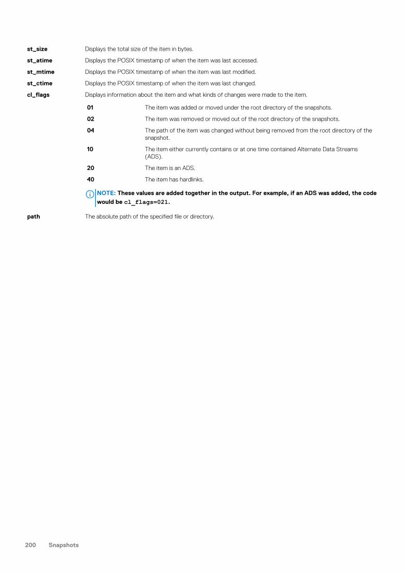
st_size Displays the total size of the item in bytes.
st_atime Displays the POSIX timestamp of when the item was last accessed.
st_mtime Displays the POSIX timestamp of when the item was last modified.
st_ctime Displays the POSIX timestamp of when the item was last changed.
cl_flags Displays information about the item and what kinds of changes were made to the item.
01 The item was added or moved under the root directory of the snapshots.
02 The item was removed or moved out of the root directory of the snapshots.
04 The path of the item was changed without being removed from the root directory of thesnapshot.
10 The item either currently contains or at one time contained Alternate Data Streams(ADS).
20 The item is an ADS.
40 The item has hardlinks.
NOTE: These values are added together in the output. For example, if an ADS was added, the code
would be cl_flags=021.
path The absolute path of the specified file or directory.
200 Snapshots

Deduplication with SmartDedupeThis section contains the following topics:
Topics:
• Deduplication overview• Deduplication jobs• Data replication and backup with deduplication• Snapshots with deduplication• Deduplication considerations• Shadow-store considerations• SmartDedupe license functionality• Managing deduplication
Deduplication overviewSmartDedupe enables you to save storage space on your cluster by reducing redundant data. Deduplication maximizes the efficiency ofyour cluster by decreasing the amount of storage required to store multiple files with identical blocks.
The SmartDedupe software module deduplicates data by scanning an Isilon cluster for identical data blocks. Each block is 8 KB. IfSmartDedupe finds duplicate blocks, SmartDedupe moves a single copy of the blocks to a hidden file called a shadow store. SmartDedupethen deletes the duplicate blocks from the original files and replaces the blocks with pointers to the shadow store.
Deduplication is applied at the directory level, targeting all files and directories underneath one or more root directories. SmartDedupe notonly deduplicates identical blocks in different files, it also deduplicates identical blocks within a single file.
You can first assess a directory for deduplication and determine the estimated amount of space you can expect to save. You can thendecide whether to deduplicate the directory. After you begin deduplicating a directory, you can monitor how much space is saved bydeduplication in real time.
For two or more files to be deduplicated, the files must have the same disk pool policy ID and protection policy. If one or both of theseattributes differs between two or more identical files, or files with identical 8K blocks, the files are not deduplicated.
Because it is possible to specify protection policies on a per-file or per-directory basis, deduplication can further be impacted. Consider theexample of two files, /ifs/data/projects/alpha/logo.jpg and /ifs/data/projects/beta/logo.jpg. Even though thelogo.jpg files in both directories are identical, if one has a different protection policy from the other, the two files would not bededuplicated.
In addition, if you have activated a SmartPools license on your cluster, you can specify custom file pool policies. These file pool policesmight cause files that are identical or have identical 8K blocks to be stored in different node pools. Consequently, those files would havedifferent disk pool policy IDs and would not be deduplicated.
SmartDedupe also does not deduplicate files that are 32 KB or smaller, because doing so would consume more cluster resources than thestorage savings are worth. The default size of a shadow store is 2 GB. Each shadow store can contain up to 256,000 blocks. Each block ina shadow store can be referenced up to 32,000 times.
Deduplication jobsDeduplication is performed by a system maintenance job referred to as a deduplication job. You can monitor and control deduplication jobsas you would any other maintenance job on the cluster. Although the overall performance impact of deduplication is minimal, thededuplication job consumes 400 MB of memory per node.
When a deduplication job runs for the first time on a cluster, SmartDedupe samples blocks from each file and creates index entries forthose blocks. If the index entries of two blocks match, SmartDedupe scans the blocks adjacent to the matching pair and then deduplicatesall duplicate blocks. After a deduplication job samples a file once, new deduplication jobs will not sample the file again until the file ismodified.
The first deduplication job that you run might take significantly longer to complete than subsequent deduplication jobs. The firstdeduplication job must scan all files under the specified directories to generate the initial index. If subsequent deduplication jobs take a long
15
Deduplication with SmartDedupe 201

time to complete, this most likely indicates that a large amount of data is being deduplicated. However, it can also indicate that users arestoring large amounts of new data on the cluster. If a deduplication job is interrupted during the deduplication process, the job willautomatically restart the scanning process from where the job was interrupted.
NOTE: You should run deduplication jobs when users are not modifying data on the cluster. If users are continually
modifying files on the cluster, the amount of space saved by deduplication is minimal because the deduplicated blocks
are constantly removed from the shadow store.
How frequently you should run a deduplication job on your Isilon cluster varies, depending on the size of your data set, the rate of changes,and opportunity. For most clusters, we recommend that you start a deduplication job every 7-10 days. You can start a deduplication jobmanually or schedule a recurring job at specified intervals. By default, the deduplication job is configured to run at a low priority. However,you can specify job controls, such as priority and impact, on deduplication jobs that run manually or by schedule.
The permissions required to modify deduplication settings are not the same as those needed to run a deduplication job. Although a usermust have the maintenance job permission to run a deduplication job, the user must have the deduplication permission to modifydeduplication settings. By default, the root user and SystemAdmin user have the necessary permissions for all deduplication operations.
Data replication and backup with deduplicationWhen deduplicated files are replicated to another Isilon cluster or backed up to a tape device, the deduplicated files no longer share blockson the target Isilon cluster or backup device. However, although you can deduplicate data on a target Isilon cluster, you cannot deduplicatedata on an NDMP backup device.
Shadows stores are not transferred to target clusters or backup devices. Because of this, deduplicated files do not consume less spacethan non-deduplicated files when they are replicated or backed up. To avoid running out of space, you must ensure that target clustersand tape devices have enough free space to store deduplicated data as if the data had not been deduplicated. To reduce the amount ofstorage space consumed on a target Isilon cluster, you can configure deduplication for the target directories of your replication policies.Although this will deduplicate data on the target directory, it will not allow SyncIQ to transfer shadow stores. Deduplication is stillperformed by deduplication jobs running on the target cluster.
The amount of cluster resources required to backup and replicate deduplicated data is the same as for non-deduplicated data. You candeduplicate data while the data is being replicated or backed up.
Snapshots with deduplicationYou cannot deduplicate the data stored in a snapshot. However, you can create snapshots of deduplicated data.
If you create a snapshot for a deduplicated directory, and then modify the contents of that directory, the references to shadow stores willbe transferred to the snapshot over time. Therefore, if you enable deduplication before you create snapshots, you will save more space onyour cluster. If you implement deduplication on a cluster that already has a significant amount of data stored in snapshots, it will take timebefore the snapshot data is affected by deduplication. Newly created snapshots can contain deduplicated data, but snapshots createdbefore deduplication was implemented cannot.
If you plan on reverting a snapshot, it is best to revert the snapshot before running a deduplication job. Restoring a snapshot can overwritemany of the files on the cluster. Any deduplicated files are reverted back to normal files if they are overwritten by a snapshot revert.However, after the snapshot revert is complete, you can deduplicate the directory and the space savings persist on the cluster.
Deduplication considerationsDeduplication can significantly increase the efficiency at which you store data. However, the effect of deduplication varies depending onthe cluster.
You can reduce redundancy on a cluster by running SmartDedupe. Deduplication creates links that can impact the speed at which you canread from and write to files. In particular, sequentially reading chunks smaller than 512 KB of a deduplicated file can be significantly slowerthan reading the same small, sequential chunks of a non-deduplicated file. This performance degradation applies only if you are readingnon-cached data. For cached data, the performance for deduplicated files is potentially better than non-deduplicated files. If you streamchunks larger than 512 KB, deduplication does not significantly impact the read performance of the file. If you intend on streaming 8 KB orless of each file at a time, and you do not plan on concurrently streaming the files, it is recommended that you do not deduplicate the files.
Deduplication is most effective when applied to static or archived files and directories. The less files are modified, the less negative effectdeduplication has on the cluster. For example, virtual machines often contain several copies of identical files that are rarely modified.Deduplicating a large number of virtual machines can greatly reduce consumed storage space.
202 Deduplication with SmartDedupe

Shadow-store considerationsShadow stores are hidden files that are referenced by cloned and deduplicated files. Files that reference shadow stores behave differentlythan other files.
• Reading shadow-store references might be slower than reading data directly. Specifically, reading non-cached shadow-storereferences is slower than reading non-cached data. Reading cached shadow-store references takes no more time than reading cacheddata.
• When files that reference shadow stores are replicated to another Isilon cluster or backed up to a Network Data ManagementProtocol (NDMP) backup device, the shadow stores are not transferred to the target Isilon cluster or backup device. The files aretransferred as if they contained the data that they reference from shadow stores. On the target Isilon cluster or backup device, thefiles consume the same amount of space as if they had not referenced shadow stores.
• When OneFS creates a shadow store, OneFS assigns the shadow store to a storage pool of a file that references the shadow store. Ifyou delete the storage pool that a shadow store resides on, the shadow store is moved to a pool occupied by another file thatreferences the shadow store.
• OneFS does not delete a shadow-store block immediately after the last reference to the block is deleted. Instead, OneFS waits untilthe ShadowStoreDelete job is run to delete the unreferenced block. If a large number of unreferenced blocks exist on the cluster,OneFS might report a negative deduplication savings until the ShadowStoreDelete job is run.
• Shadow stores are protected at least as much as the most protected file that references it. For example, if one file that references ashadow store resides in a storage pool with +2 protection and another file that references the shadow store resides in a storage poolwith +3 protection, the shadow store is protected at +3.
• Quotas account for files that reference shadow stores as if the files contained the data referenced from shadow stores; from theperspective of a quota, shadow-store references do not exist. However, if a quota includes data protection overhead, the quota doesnot account for the data protection overhead of shadow stores.
SmartDedupe license functionalityYou can deduplicate data only if you activate a SmartDedupe license on a cluster. However, you can assess deduplication savings withoutactivating a SmartDedupe license.
If you activate a SmartDedupe license, and then deduplicate data, the space savings are not lost if the license becomes inactive. You canalso still view deduplication savings while the license is inactive. However, you will not be able to deduplicate additional data until you re-activate the SmartDedupe license.
Managing deduplicationYou can manage deduplication on a cluster by first assessing how much space you can save by deduplicating individual directories. Afteryou determine which directories are worth deduplicating, you can configure SmartDedupe to deduplicate those directories specifically. Youcan then monitor the actual amount of disk space you are saving.
Assess deduplication space savingsYou can assess the amount of disk space you will save by deduplicating a directory.
1. Specify which directory to assess by running the isi dedupe settings modify command.
The following command configures SmartDedupe to assess deduplication savings for /ifs/data/archive:
isi dedupe settings modify --assess-paths /ifs/data/archive
If you assess multiple directories, disk savings will not be differentiated by directory in the deduplication report.
2. Start the assessment job by running the following command:
isi job jobs start DedupeAssessment
3. Identify the ID of the assessment report by running the following command:
isi dedupe reports list
4. View prospective space savings by running the isi dedupe reports view command:
Deduplication with SmartDedupe 203

The following command displays the prospective savings recorded in a deduplication report with an ID of 46:
isi dedupe reports view 46
Specify deduplication settingsYou can specify which directories you want to deduplicate.
1. Specify which directories you want to deduplicate by running the isi dedupe settings modify command.
The following command targets /ifs/data/archive and /ifs/data/media for deduplication:
isi dedupe settings modify --paths /ifs/data/media,/ifs/data/archive
2. Optional: To modify the settings of the deduplication job, run the isi job types modify command.
The following command configures the deduplication job to be run every Friday at 10:00 PM:
isi job types modify Dedupe --schedule "Every Friday at 10:00 PM"
View deduplication space savingsYou can view the amount of disk space that you are currently saving with deduplication.
Run the following command:
isi dedupe stats
View a deduplication reportAfter a deduplication job completes, you can view information about the job in a deduplication report.
1. Optional: To identify the ID of the deduplication report you want to view, run the following command:
isi dedupe reports list
2. View a deduplication report by running the isi dedupe reports view command.
The following command displays a deduplication report with an ID of 44:
isi dedupe reports view 44
Deduplication job report informationYou can view the following deduplication specific information in deduplication job reports:
Start time The time the deduplication job started.
End time The time the deduplication job ended.
Iteration Count The number of times that SmartDedupe interrupted the sampling process. If SmartDedupe is sampling a largeamount of data, SmartDedupe might interrupt sampling in order to start deduplicating the data. AfterSmartDedupe finishes deduplicating the sampled data, SmartDedupe will continue sampling the remaining data.
Scanned blocks The total number of blocks located underneath the specified deduplicated directories.
Sampled blocks The number of blocks that SmartDedupe created index entries for.
Deduped blocks The number of blocks that were deduplicated.
Dedupe percent The percentage of scanned blocks that were deduplicated.
204 Deduplication with SmartDedupe

Created deduperequests
The total number of deduplication requests created. A deduplication request is created for each matching pair ofdata blocks. For example, if you have 3 data blocks that all match, SmartDedupe creates 2 requests. One of therequests could pair file1 and file2 together and the other request could pair file2 and file3 together.
Successful deduperequests
The number of deduplication requests that completed successfully.
Failed deduperequests
The number of deduplication requests that failed. If a deduplication request fails, it doesn't mean that the job failedtoo. A deduplication request can fail for any number of reasons. For example, the file might have been modifiedsince it was sampled.
Skipped files The number of files that were not scanned by the deduplication job. SmartDedupe skips files for a number ofreasons. For example, SmartDedupe skips files that have already been scanned and haven't been modified since.SmartDedupe also skips all files that are smaller than 4 KB.
Index entries The number of entries that currently exist in the index.
Index lookupattempts
The total number of lookups that have been done by earlier deduplication jobs plus the number of lookups done bythis deduplication job. A lookup is when the deduplication job attempts to match a block that was indexed with ablock that hasn't been indexed.
Index lookup hits The number of blocks that matched index entries.
Deduplication informationYou can view information about how much disk space is being saved by deduplication.
The following information is displayed in the output of the isi dedupe stats command:
Cluster PhysicalSize
The total amount of physical disk space on the cluster.
Cluster Used Size The total amount of disk space currently occupied by data on the cluster.
Logical SizeDeduplicated
The amount of disk space that has been deduplicated in terms of reported file sizes. For example, if you havethree identical files that are all 5 GB, the logical size deduplicated is 15 GB.
Logical Saving The amount of disk space saved by deduplication in terms of reported file sizes. For example, if you have threeidentical files that are all 5 GB, the logical saving is 10 GB.
Estimated SizeDeduplicated
The total amount of physical disk space that has been deduplicated, including protection overhead and metadata.For example, if you have three identical files that are all 5 GB, the estimated size deduplicated would be greaterthan 15 GB, because of the disk space consumed by file metadata and protection overhead.
EstimatedPhysical Saving
The total amount of physical disk space saved by deduplication, including protection overhead and metadata. Forexample, if you have three identical files that are all 5 GB, the estimated physical saving would be greater than 10GB, because deduplication saved space that would have been occupied by file metadata and protection overhead.
Deduplication with SmartDedupe 205

Inline Data DeduplicationInline data deduplication performs deduplication of data before the data is committed to disk.
Topics:
• Inline Data Deduplication overview• Inline deduplication interoperability• Considerations for using inline deduplication• Enable inline deduplication• Verify inline deduplication is enabled• View inline deduplication reports• Disable or pause inline deduplication• Remove deduplication• Assess inline deduplication space savings• Troubleshoot index allocation issues
Inline Data Deduplication overviewInline data deduplication for Generation 6 F810 nodes deduplicates data before the data is committed to disk. Deduplicating data before itis committed avoids redundant writes to disk and improves the wear life of flash drives.
Inline data deduplication (inline deduplication) includes inline zero block elimination, asynchronous data deduplication, and an in-memory,non-persistent index table. Inline deduplication is supported only on F810 disk pools and requires OneFS 8.2.1 or later on all nodes.
Depending on workload, the data reduction rate with inline compression and inline data deduplication enabled is typically around 3:1.
No license is required for inline data deduplication.
Inline deduplication is a cluster-wide setting and is disabled by default. After you enable the feature, it is always on, applies globally, andapplies to all files on disk pools that support data reduction. Exceptions include:
• Packed files• Writes to snapshots, though deduplicated data can be copied on write to snapshots• Shadow stores• Stubbed files, such as CloudPools files• Files with the no_dedupe attribute set
You cannot selectively enable inline deduplication on individual files.
Two files with identical data blocks or a file and a shadow store with identical data blocks must have the same disk pool policy ID to bededuplicated. Data is deduplicated to a shadow store using a protection policy that is at least as high as the protection policy of the files tobe deduplicated.
NOTE: The "always on" aspect of inline deduplication can affect performance. Inline deduplication may not be suitable
for performance-sensitive workloads. More guidance is available in Considerations for using inline deduplication.
You must have the ISI_PRIV_CLUSTER privilege to enable or disable inline deduplication.
You enable inline deduplication from the command line:
isi dedupe inline settings modify --mode enabled
Comparing inline deduplication with SmartDedupeThe following table compares inline deduplication with the SmartDedupe service.
16
206 Inline Data Deduplication

Inline deduplication SmartDedupe
Globally enabled Directory tree based
Processes small files Skips files less than 32KB by default
Deduplicates sequential runs of blocks of matching data to singleblocks
Can only deduplicate between files
Per node, non-persistent in-memory index Large persistent on-disk index
Can convert copy operations to clone Post process only
Opportunistic Exhaustive
No license required License required
Inline deduplication workflowInline deduplication begins when data is flushed from the SmartCache (also referred to as the coalescer). The stages are:
• SmartCache (coalescer) flush• Determine the data to copy on write to snapshots• Remove zero blocks• Replace duplicate data with shadow store references• Compress the data• Write to storage
Zero block elimination is performed before inline deduplication. Files that are not eligible for deduplication may still have zero blocksremoved. Data blocks that contain only zeros are detected and prevented from being written to disk. This can reduce the work requiredby inline deduplication and data compression.
The in-memory index tableInline deduplication uses an in-memory index table to track dedupable data blocks. The index table is allocated on each node that supportsthe feature. Allocating the index table depends on available resources.
Inline deduplication is an opportunistic best effort service and is not a substitute for the SmartDedupe service. However, inlinededuplication can reduce the amount of work that SmartDedupe has to do.
The default size of the index table is 10% of RAM up to a maximum of 16 GB. Each node has its own index: there is no sharing betweennodes. Because the index is in-memory only, its contents are lost on reboot.
If you enable inline deduplication on a system that is just booting up, index allocation should happen quickly. If the system has been runningfor a while, locating the memory required for the index table may be difficult. In that case, index allocation can take longer and, if there isinsufficient memory, can fail. See Troubleshoot index allocation issues for guidance.
The newly-allocated index table is empty. Inline deduplication hashes data blocks as they are read and records the results in the indextable. Data is deduplicated immediately if inline deduplication encounters matching data blocks right away. Over time, finding matchingdata becomes more effective as the index accumulates file system data.
The following describes the deduplication process when an initial data match is found between two files.
1. The data being written is redirected to a shadow store2. Shadow references are inserted into the current file3. Inline deduplication queues an asynchronous worker process to deduplicate the matching file with the shadow store
After the initial match, inline deduplication compares data being written with the data in the shadow store. If it finds a match, it updatesthe current file with shadow references: there is no need to write data to storage. Subsequent data matches are typically much fasterthan the initial match since they involve less work.
Inline deduplication upgrade considerationsThe following are upgrade considerations for using inline deduplication.
• OneFS 8.2.1 or later must be running on all nodes in the cluster.• Disk pools that can support inline deduplication must have the data_reduce flag set.
Inline Data Deduplication 207

• The data_reduce flag is set automatically on upgrade commit on all disk pools that support compression and inline deduplication
• Use the disi diskpool list -v command to see the data_reduce flag.
Inline deduplication interoperabilityInline deduplication interoperates with OneFS as follows.
SmartDedupe Use to find deduplication matches not found by inline deduplication.
Data compression Inline deduplication operates on uncompressed data. Data written to shadow stores is compressed.
Snapshots Writes to snapshots are not inline deduplicated, but deduplicated data can be copied on write to snapshots.
Packing (SmallFile StorageEfficiency)
Packed files are skipped by inline deduplication, though zero block elimination still occurs.
Backup andrestore
Backup and inline deduplication interoperate in the same way that backup and SmartDedupe interoperate. Filesthat were deduplicated using inline deduplication are indistinguishable from files that were deduplicated usingSmartDedupe, and the same conditions apply. The local file remains deduplicated on disk. Files are rehydrated onread and the full file contents are backed up. As with SmartDedupe, ensure that the target clusters or backupdevices have enough space to accommodate un-deduplicated files. However, transferring data to another Isiloncluster that has inline deduplication enabled can help you to avoid requiring the full rehydrated capacity on thetarget cluster.
Considerations for using inline deduplicationThis section describes considerations for using (or not using) inline deduplication.
Enabling inline deduplication can be advantageous if your users or workload have characteristics such as the following.
• If your users frequently copy files, either large files or whole data sets. In this case, inline deduplication can effectively turn theseoperations into clone operations.
• If you want to reduce writes to storage to preserve flash drive wear life, inline deduplication can help.• If your workloads involve lots of small files (such as EDA), those small files are deduplicated more efficiently with inline deduplication.
By default, SmartDedupe skips small files.• If your data sets contain a large amount of zeroed data, storage savings are available from that alone.
You may not need inline deduplication if:
• Your data sets have little or no deduplication.• You prefer to run SmartDedupe during off hours. Inline deduplication is always on.• Your workload is performance sensitive. Inline deduplication may add too much overhead.
Enable inline deduplicationEnable inline deduplication from the command line.
You can enable inline deduplication only on F810 nodes. Once inline deduplication is enabled, it is always on and applies globally, cluster-wide.
You must have the ISI_PRIV_CLUSTER privilege to administer inline deduplication.
1. Log in to your cluster as a user with the administrator role.2. Enter the following command: isi dedupe inline settings modify --mode enabledInline deduplication is enabled.
Verify inline deduplication is enabledYou can verify that inline deduplication is enabled either globally or by checking each node manually.
You must have the ISI_PRIV_CLUSTER privilege to administer inline deduplication.
1. Log in to your cluster as a user with the administrator role.
208 Inline Data Deduplication

2. To check whether inline deduplication is enabled globally, enter the following command:
# isi_for_array isi_inline_dedupe_status
If the command returns OK, inline deduplication is globally enabled.3. To check each node manually, enter the following command:
# isi_for_array sysctl efs.sfm.inline_dedupe.mode
Each node returns its status. If the status is enabled, inline deduplication is active on that node. For example:
node-1: efs.sfm.inline_dedupe.mode: enablednode-2: efs.sfm.inline_dedupe.mode:enablednode-3: efs.sfm.inline_dedupe.mode:enabled
View inline deduplication reportsYou can view reports to monitor the results of inline deduplication on your F810 clusters.
You must have the ISI_PRIV_CLUSTER privilege to administer inline deduplication.
1. Log in to your cluster as a user with the administrator role.2. To view data reduction statistics, enter the following command:
# isi statistics data-reduction
A report similar to the following appears.
Recent Writes (5 mins) Cluster Data Reduction ----------------------------------- -----------------------------------------Logical data 9.93M Est. logical data 1.31TZero-removal saved 0 Deduplication saved 16.00k Dedupe saved 611.10GCompression saved 7.93M Est. compression saved 543.21GPreprotected physical 1.98M Est. preprotected physical 186.70GProtection overhead 4.40M Est. protection overhead 62.23GProtected physical 6.38M Protected physical 248.93G Duplication ratio 1.00 : 1 Est. dedupe ratio 1.84 : 1Compression ratio 5.00 : 1 Est. compression ratio 3.91 : 1Data reduction ratio 5.00 : 1 Est. data reduction ratio 7.18 : 1Efficiency ratio 1.55 : 1 Est. storage efficiency ratio 5.39 : 1
3. To view inline deduplication statistics, enter the following command:
# isi dedupe stats
Statistics similar to the following appear:
Cluster Physical Size: 86.14T Cluster Used Size: 248.93G Logical Size Deduplicated: 1.17T Logical Saving: 611.10G Estimated Size Deduplicated: 124.11G Estimated Physical Saving: 63.20G
Disable or pause inline deduplicationYou can disable or pause inline deduplication.
Disabling inline deduplication deactivates inline deduplication and de-allocates the index table. Pausing inline deduplication deactivates inlinededuplication but leaves the index table intact.
Inline Data Deduplication 209

NOTE: Disabling inline deduplication does not remove the effects of deduplication. See Remove deduplication.
You must have the ISI_PRIV_CLUSTER privilege to administer inline deduplication.
1. Log in to your cluster as a user with the administrator role.2. To disable inline deduplication, enter the following command:
# isi dedupe inline settings modify --mode disabled
3. To pause deduplication, enter the following command:
# isi dedupe inline settings modify --mode paused
Remove deduplicationYou can remove the effects of inline deduplication.
Disabling inline deduplication does not remove its effects. To reverse deduplication, you must manually un-deduplicate the affected databy running the undedupe job on each affected path.
You must have the ISI_PRIV_CLUSTER privilege to administer inline deduplication.
1. Log in to the cluster as a user with the adminstrator role.2. Run the undedupe job on each affected path, similar to the following:
# isi job start undedupe --paths <path>
Where <path> is an absolute path within the /ifs file system.
Assess inline deduplication space savingsYou can assess potential space savings from inline deduplication by running the DedupeAssessment job or by enabling inline deduplicationin assessment mode.
You must have the ISI_PRIV_CLUSTER privilege to administer inline deduplication.
1. Enable inline deduplication in assessment mode:
# isi dedupe inline settings modify --assess
2. Check the following statistics from each node:
# sysctl efs.sfm.inline_dedupe.stats.zero_block# sysctl efs.sfm.inline_dedupe.stats.dedupe_block# sysctl efs.sfm.inline_dedupe.stats.write_block
The approximate deduplication rate is dedupe_block/write_block * 100%.
Troubleshoot index allocation issuesThis section describes what to do if index allocation fails.
The in-memory index requires allocating chunks of physically contiguous memory. On a running system this may not be possible. Checkthe inline deduplication state:
isi_inline_dedupe_status
The isi_inline_dedupe_status command reports whether the index failed to allocate or if its allocation is not optimal. If the indexcannot be allocated, inline deduplication will attempt a non-optimal layout. If the non-optimal layout fails, inline deduplication will reduce thesize of the index until it can be successfully allocated.
Running isi_flush on the node may clear enough memory to allocate a full index.
210 Inline Data Deduplication

Data replication with SyncIQThis section contains the following topics:
Topics:
• SyncIQ data replication overview• Replication policies and jobs• Replication snapshots• Data failover and failback with SyncIQ• Recovery times and objectives for SyncIQ• Replication policy priority• SyncIQ license functionality• Creating replication policies• Managing replication to remote clusters• Initiating data failover and failback with SyncIQ• Performing disaster recovery for older SmartLock directories• Managing replication policies• Managing replication to the local cluster• Managing replication performance rules• Managing replication reports• Managing failed replication jobs
SyncIQ data replication overviewOneFS enables you to replicate data from one Isilon cluster to another through the SyncIQ software module. You must activate a SyncIQlicense on both Isilon clusters before you can replicate data between them.
You can replicate data at the directory level while optionally excluding specific files and sub-directories from being replicated. SyncIQcreates and references snapshots to replicate a consistent point-in-time image of a source directory. Metadata such as access controllists (ACL) and alternate data streams (ADS) are replicated along with data.
SyncIQ enables you to maintain a consistent replica of your data on another Isilon cluster and to control the frequency of data replication.For example, you could configure SyncIQ to back up data from your primary cluster to a secondary cluster once a day at 10 PM.Depending on the size of your data set, the first replication operation could take considerable time. After that, however, replicationoperations would complete more quickly.
SyncIQ also offers automated failover and failback capabilities so you can continue operations on the secondary Isilon cluster should yourprimary cluster become unavailable.
It is recommended that you use encryption or a pre-shared key (PSK) when using SyncIQ . See article 542907 for more information.
Replication policies and jobsData replication is coordinated according to replication policies and replication jobs. Replication policies specify what data is replicated,where the data is replicated to, and how often the data is replicated. Replication jobs are the operations that replicate data from one Isiloncluster to another. SyncIQ generates replication jobs according to replication policies.
A replication policy specifies two clusters: the source and the target. The cluster on which the replication policy exists is the sourcecluster. The cluster that data is being replicated to is the target cluster. When a replication policy starts, SyncIQ generates a replication jobfor the policy. When a replication job runs, files from a directory tree on the source cluster are replicated to a directory tree on the targetcluster; these directory trees are known as source and target directories.
After the first replication job created by a replication policy finishes, the target directory and all files contained in the target directory areset to a read-only state, and can be modified only by other replication jobs belonging to the same replication policy. We recommend thatyou do not create more than 1,000 policies on a cluster.
17
Data replication with SyncIQ 211

NOTE: To prevent permissions errors, make sure that ACL policy settings are the same across source and target
clusters.
You can create two types of replication policies: synchronization policies and copy policies. A synchronization policy maintains an exactreplica of the source directory on the target cluster. If a file or sub-directory is deleted from the source directory, the file or directory isdeleted from the target cluster when the policy is run again.
You can use synchronization policies to fail over and fail back data between source and target clusters. When a source cluster becomesunavailable, you can fail over data on a target cluster and make the data available to clients. When the source cluster becomes availableagain, you can fail back the data to the source cluster.
A copy policy maintains recent versions of the files that are stored on the source cluster. However, files that are deleted on the sourcecluster are not deleted from the target cluster. Failback is not supported for copy policies. Copy policies are most commonly used forarchival purposes.
Copy policies enable you to remove files from the source cluster without losing those files on the target cluster. Deleting files on thesource cluster improves performance on the source cluster while maintaining the deleted files on the target cluster. This can be useful if,for example, your source cluster is being used for production purposes and your target cluster is being used only for archiving.
After creating a job for a replication policy, SyncIQ must wait until the job completes before it can create another job for the policy. Anynumber of replication jobs can exist on a cluster at a given time; however, no more than 50 replication jobs can run on a source cluster atthe same time. If more than 50 replication jobs exist on a cluster, the first 50 jobs run while the others are queued to run.
There is no limit to the number of replication jobs that a target cluster can support concurrently. However, because more replication jobsrequire more cluster resources, replication will slow down as more concurrent jobs are added.
When a replication job runs, OneFS generates workers on the source and target cluster. Workers on the source cluster read and send datawhile workers on the target cluster receive and write data.
You can replicate any number of files and directories with a single replication job. You can prevent a large replication job fromoverwhelming the system by limiting the amount of cluster resources and network bandwidth that data synchronization is allowed toconsume. Because each node in a cluster is able to send and receive data, the speed at which data is replicated increases for largerclusters.
Automated replication policiesYou can manually start a replication policy at any time, but you can also configure replication policies to start automatically based on sourcedirectory modifications or schedules.
You can configure a replication policy to run according to a schedule, so that you can control when replication is performed. You can alsoconfigure policies to replicate the data captured in snapshots of a directory. You can also configure a replication policy to start whenSyncIQ detects a modification to the source directory, so that SyncIQ maintains a more current version of your data on the target cluster.
Scheduling a policy can be useful under the following conditions:
• You want to replicate data when user activity is minimal• You can accurately predict when modifications will be made to the data
If a policy is configured to run according to a schedule, you can configure the policy not to run if no changes have been made to thecontents of the source directory since the job was last run. However, if changes are made to the parent directory of the source directoryor a sibling directory of the source directory, and then a snapshot of the parent directory is taken, SyncIQ will create a job for the policy,even if no changes have been made to the source directory. Also, if you monitor the cluster through the File System Analytics (FSA)feature of InsightIQ, the FSA job will create snapshots of /ifs, which will most likely cause a replication job to start whenever the FSA jobis run.
Replicating data contained in snapshots of a directory can be useful under the following conditions:
• You want to replicate data according to a schedule, and you are already generating snapshots of the source directory through asnapshot schedule
• You want to maintain identical snapshots on both the source and target cluster• You want to replicate existing snapshots to the target cluster
To do this, you must enable archival snapshots on the target cluster. This setting can only been enabled when the policy is created.
If a policy is configured to replicate snapshots, you can configure SyncIQ to replicate only snapshots that match a specified namingpattern.
Configuring a policy to start when changes are made to the source directory can be useful under the following conditions:
• You want to retain a up-to-date copy of your data at all times• You are expecting a large number of changes at unpredictable intervals
212 Data replication with SyncIQ

For policies that are configured to start whenever changes are made to the source directory, SyncIQ checks the source directories everyten seconds. SyncIQ checks all files and directories underneath the source directory, regardless of whether those files or directories areexcluded from replication, so SyncIQ might occasionally run a replication job unnecessarily. For example, assume that newPolicyreplicates /ifs/data/media but excludes /ifs/data/media/temp. If a modification is made to /ifs/data/media/temp/file.txt, SyncIQ will run newPolicy, even though /ifs/data/media/temp/file.txt will not be replicated.
If a policy is configured to start whenever changes are made to the source directory, and a replication job fails, SyncIQ waits one minutebefore attempting to run the policy again. SyncIQ increases this delay exponentially for each failure up to a maximum of eight hours. Youcan override the delay by running the policy manually at any time. After a job for the policy completes successfully, SyncIQ will resumechecking the source directory every ten seconds.
If a policy is configured to start whenever changes are made to the source directory, you can configure SyncIQ to wait a specified periodof time after the source directory is modified before starting a job.
NOTE: To avoid frequent synchronization of minimal sets of changes, and overtaxing system resources, we strongly
advise against configuring continuous replication when the source directory is highly active. In such cases, it is often
better to configure continuous replication with a change-triggered delay of several hours to consolidate groups of
changes.
Source and target cluster associationSyncIQ associates a replication policy with a target cluster by marking the target cluster when the job runs for the first time. Even if youmodify the name or IP address of the target cluster, the mark persists on the target cluster. When a replication policy is run, SyncIQchecks the mark to ensure that data is being replicated to the correct location.
On the target cluster, you can manually break an association between a replication policy and target directory. Breaking the associationbetween a source and target cluster causes the mark on the target cluster to be deleted. You might want to manually break a targetassociation if an association is obsolete. If you break the association of a policy, the policy is disabled on the source cluster and you cannotrun the policy. If you want to run the disabled policy again, you must reset the replication policy.
Breaking a policy association causes either a full replication or differential replication to occur the next time you run the replication policy.During a full or differential replication, SyncIQ creates a new association between the source and target clusters. Depending on theamount of data being replicated, a full or differential replication can take a very long time to complete.
CAUTION: Changes to the configuration of the target cluster outside of SyncIQ can introduce an error condition that
effectively breaks the association between the source and target cluster. For example, changing the DNS record of the
target cluster could cause this problem. If you need to make significant configuration changes to the target cluster
outside of SyncIQ, make sure that your SyncIQ policies can still connect to the target cluster.
Configuring SyncIQ source and target clusters with NATSource and target clusters can use NAT (network address translation) for SyncIQ failover and failback purposes, but must be configuredappropriately.
In this scenario, source and target clusters are typically at different physical locations, use private, non-routable address space, and do nothave direct connections to the Internet. Each cluster typically is assigned a range of private IP addresses. For example, a cluster with 12nodes might be assigned IP addresses 192.168.10.11 to 192.168.10.22.
To communicate over the public Internet, source and target clusters must have all incoming and outgoing data packets appropriatelytranslated and redirected by a NAT-enabled firewall or router.
CAUTION: SyncIQ data is not encrypted. Running SyncIQ jobs over the public Internet provides no protection against
data theft.
SyncIQ enables you to limit replication jobs to particular nodes within your cluster. For example, if your cluster was made up of 12 nodes,you could limit replication jobs to just three of those nodes. For NAT support, you would need to establish a one-for-one associationbetween the source and target clusters. So, if you are limiting replication jobs to three nodes on your source cluster, you must associatethree nodes on your target cluster.
In this instance, you would need to configure static NAT, sometimes referred to as inbound mapping. On both the source and targetclusters, for the private address assigned to each node, you would associate a static NAT address. For example:
Data replication with SyncIQ 213

Source cluster Target Cluster
Node name Private address NAT address Node name Private address NAT address
source-1 192.168.10.11 10.8.8.201 target-1 192.168.55.101 10.1.2.11
source-2 192.168.10.12 10.8.8.202 target-2 192.168.55.102 10.1.2.12
source-3 192.168.10.13 10.8.8.203 target-3 192.168.55.103 10.1.2.13
To configure static NAT, you would need to edit the /etc/local/hosts file on all six nodes, and associate them with theircounterparts by adding the appropriate NAT address and node name. For example, in the /etc/local/hosts file on the three nodes ofthe source cluster, the entries would look like:
10.1.2.11 target-1
10.1.2.12 target-2
10.1.2.13 target-3Similarly, on the three nodes of the target cluster, you would edit the /etc/local/hosts file, and insert the NAT address and name ofthe associated node on the source cluster. For example, on the three nodes of the target cluster, the entries would look like:
10.8.8.201 source-1
10.8.8.202 source-2
10.8.8.203 source-3When the NAT server receives packets of SyncIQ data from a node on the source cluster, the NAT server replaces the packet headersand the node's port number and internal IP address with the NAT server's own port number and external IP address. The NAT server onthe source network then sends the packets through the Internet to the target network, where another NAT server performs a similarprocess to transmit the data to the target node. The process is reversed when the data fails back.
With this type of configuration, SyncIQ can determine the correct addresses to connect with, so that SyncIQ can send and receive data.In this scenario, no SmartConnect zone configuration is required.
For information about the ports used by SyncIQ, see the OneFS Security Configuration Guide for your OneFS version.
Full and differential replicationIf a replication policy encounters an issue that cannot be fixed (for example, if the association was broken on the target cluster), you mightneed to reset the replication policy. If you reset a replication policy, SyncIQ performs either a full replication or a differential replication thenext time the policy is run. You can specify the type of replication that SyncIQ performs.
During a full replication, SyncIQ transfers all data from the source cluster regardless of what data exists on the target cluster. A fullreplication consumes large amounts of network bandwidth and can take a very long time to complete. However, a full replication is lessstrenuous on CPU usage than a differential replication.
During a differential replication, SyncIQ first checks whether a file already exists on the target cluster and then transfers only data thatdoes not already exist on the target cluster. A differential replication consumes less network bandwidth than a full replication; however,differential replications consume more CPU. Differential replication can be much faster than a full replication if there is an adequateamount of available CPU for the replication job to consume.
Controlling replication job resource consumptionYou can create rules that limit the network traffic created by replication jobs, the rate at which files are sent by replication jobs, thepercent of CPU used by replication jobs, and the number of workers created for replication jobs.
If you limit the percentage of total workers that SyncIQ can create, the limit is applied to the total amount of workers that SyncIQ couldcreate, which is determined by cluster hardware. Workers on the source cluster read and send data while workers on the target clusterreceive and write data.
NOTE: File-operation rules might not work accurately for files that can take more than a second to transfer and for files
that are not predictably similar in size.
214 Data replication with SyncIQ

Replication policy priorityWhen creating a replication policy, you can configure a policy to have priority over other jobs.
If multiple replication jobs are queued to be run because the maximum number of jobs are already running, jobs created by policies withpriority will be run before jobs without priorities. For example, assume that 50 jobs are currently running. A job without priority is thecreated and queued to run; next, a job with priority is created and queued to run. The job with priority will run next, even though the jobwithout priority has been queued for a longer period of time.
SyncIQ will also pause replication jobs without priority to allow jobs with priority to run. For example, assume that 50 jobs are alreadyrunning, and one of them does not have priority. If a replication job with priority is created, SyncIQ will pause the replication job withoutpriority and run the job with priority.
Replication reportsAfter a replication job completes, SyncIQ generates a replication report that contains detailed information about the job, including how longthe job ran, how much data was transferred, and what errors occurred.
If a replication report is interrupted, SyncIQ might create a subreport about the progress of the job so far. If the job is then restarted,SyncIQ creates another subreport about the progress of the job until the job either completes or is interrupted again. SyncIQ creates asubreport each time the job is interrupted until the job completes successfully. If multiple subreports are created for a job, SyncIQcombines the information from the subreports into a single report.
SyncIQ routinely deletes replication reports. You can specify the maximum number of replication reports that SyncIQ retains and thelength of time that SyncIQ retains replication reports. If the maximum number of replication reports is exceeded on a cluster, SyncIQdeletes the oldest report each time a new report is created.
You cannot customize the content of a replication report.
NOTE: If you delete a replication policy, SyncIQ automatically deletes any reports that were generated for that policy.
Replication snapshotsSyncIQ generates snapshots to facilitate replication, failover, and failback between Isilon clusters. Snapshots generated by SyncIQ can alsobe used for archival purposes on the target cluster.
Source cluster snapshotsSyncIQ generates snapshots on the source cluster to ensure that a consistent point-in-time image is replicated and that unaltered data isnot sent to the target cluster.
Before running a replication job, SyncIQ creates a snapshot of the source directory. SyncIQ then replicates data according to the snapshotrather than the current state of the cluster, allowing users to modify source directory files while ensuring that an exact point-in-time imageof the source directory is replicated.
For example, if a replication job of /ifs/data/dir/ starts at 1:00 PM and finishes at 1:20 PM, and /ifs/data/dir/file ismodified at 1:10 PM, the modifications are not reflected on the target cluster, even if /ifs/data/dir/file is not replicated until 1:15PM.
You can replicate data according to a snapshot generated with the SnapshotIQ software module. If you replicate data according to aSnapshotIQ snapshot, SyncIQ does not generate another snapshot of the source directory. This method can be useful if you want toreplicate identical copies of data to multiple Isilon clusters.
SyncIQ generates source snapshots to ensure that replication jobs do not transfer unmodified data. When a job is created for a replicationpolicy, SyncIQ checks whether it is the first job created for the policy. If it is not the first job created for the policy, SyncIQ compares thesnapshot generated for the earlier job with the snapshot generated for the new job.
SyncIQ replicates only data that has changed since the last time a snapshot was generated for the replication policy. When a replicationjob is completed, SyncIQ deletes the previous source-cluster snapshot and retains the most recent snapshot until the next job is run.
Data replication with SyncIQ 215

Target cluster snapshotsWhen a replication job is run, SyncIQ generates a snapshot on the target cluster to facilitate failover operations. When the next replicationjob is created for the replication policy, the job creates a new snapshot and deletes the old one.
If a SnapshotIQ license has been activated on the target cluster, you can configure a replication policy to generate additional snapshotsthat remain on the target cluster even as subsequent replication jobs run.
SyncIQ generates target snapshots to facilitate failover on the target cluster regardless of whether a SnapshotIQ license has beenconfigured on the target cluster. Failover snapshots are generated when a replication job completes. SyncIQ retains only one failoversnapshot per replication policy, and deletes the old snapshot after the new snapshot is created.
If a SnapshotIQ license has been activated on the target cluster, you can configure SyncIQ to generate archival snapshots on the targetcluster that are not automatically deleted when subsequent replication jobs run. Archival snapshots contain the same data as thesnapshots that are generated for failover purposes. However, you can configure how long archival snapshots are retained on the targetcluster. You can access archival snapshots the same way that you access other snapshots generated on a cluster.
Data failover and failback with SyncIQSyncIQ enables you to perform automated data failover and failback operations between Isilon clusters. If your primary cluster goes offline,you can fail over to a secondary Isilon cluster, enabling clients to continue accessing their data. If the primary cluster becomes operationalagain, you can fail back to the primary cluster.
For the purposes of SyncIQ failover and failback, the cluster originally accessed by clients is referred to as the primary cluster. The clusterthat client data is replicated to is referred to as the secondary cluster.
Failover is the process that allows clients to access, view, modify, and delete data on a secondary cluster. Failback is the process thatallows clients to resume their workflow on the primary cluster. During failback, any changes made to data on the secondary cluster arecopied back to the primary cluster by means of a replication job using a mirror policy.
Failover and failback can be useful in disaster recovery scenarios. For example, if a primary cluster is damaged by a natural disaster, youcan migrate clients to a secondary cluster where they can continue normal operations. When the primary cluster is repaired and backonline, you can migrate clients back to operations on the primary cluster.
You can fail over and fail back to facilitate scheduled cluster maintenance, as well. For example, if you are upgrading the primary cluster,you might want to migrate clients to a secondary cluster until the upgrade is complete and then migrate clients back to the primarycluster.
NOTE: Data failover and failback is supported both for enterprise and compliance SmartLock directories. Compliance
SmartLock directories adhere to U.S. Securities and Exchange Commission (SEC) regulation 17a-4(f), which requires
securities brokers and dealers to preserve records in a non-rewritable, non-erasable format. SyncIQ properly maintains
compliance with the 17a-4(f) regulation during failover and failback.
Data failoverFailover is the process of preparing data on a secondary cluster and switching over to the secondary cluster for normal client operations.After you fail over to a secondary cluster, you can direct clients to access, view, and modify their data on the secondary cluster.
Before failover is performed, you must create and run a SyncIQ replication policy on the primary cluster. You initiate the failover processon the secondary cluster. To migrate data from the primary cluster that is spread across multiple replication policies, you must initiatefailover for each replication policy.
If the action of a replication policy is set to copy, any file that was deleted on the primary cluster will still be present on the secondarycluster. When the client connects to the secondary cluster, all files that were deleted on the primary cluster will be available.
If you initiate failover for a replication policy while an associated replication job is running, the failover operation completes but thereplication job fails. Because data might be in an inconsistent state, SyncIQ uses the snapshot generated by the last successful replicationjob to revert data on the secondary cluster to the last recovery point.
If a disaster occurs on the primary cluster, any modifications to data that were made after the last successful replication job started arenot reflected on the secondary cluster. When a client connects to the secondary cluster, their data appears as it was when the lastsuccessful replication job was started.
216 Data replication with SyncIQ

Data failbackFailback is the process of restoring primary and secondary clusters to the roles that they occupied before a failover operation. Afterfailback is complete, the primary cluster holds the latest data set and resumes normal operations, including hosting clients and replicatingdata to the secondary cluster through SyncIQ replication policies in place.
The first step in the failback process is updating the primary cluster with all of the modifications that were made to the data on thesecondary cluster. The next step is preparing the primary cluster to be accessed by clients. The final step is resuming data replication fromthe primary to the secondary cluster. At the end of the failback process, you can redirect users to resume data access on the primarycluster.
To update the primary cluster with the modifications that were made on the secondary cluster, SyncIQ must create a SyncIQ domain forthe source directory.
You can fail back data with any replication policy that meets all of the following criteria:
• The policy has been failed over.• The policy is a synchronization policy (not a copy policy).• The policy does not exclude any files or directories from replication.
SmartLock compliance mode failover and failbackUsing OneFS 8.0.1 and later releases, you can replicate SmartLock compliance mode domains to a target cluster. This support includesfailover and failback of these SmartLock domains.
Because SmartLock compliance mode adheres to the U.S. Securities and Exchange Commission (SEC) regulation 17a-4(f), failover andfailback of a compliance mode WORM domain requires some planning and setup.
Most importantly, both your primary (source) and secondary (target) clusters must be configured at initial setup as compliance modeclusters. This process is described in the Isilon installation guide for your node model (for example, the Isilon S210 Installation Guide).
In addition, both clusters must have directories defined as WORM domains with the compliance type. For example, if you are storing yourWORM files in the SmartLock compliance domain /ifs/financial-records/locked on the primary cluster, you must have aSmartLock compliance domain on the target cluster to fail over to. Although the source and target SmartLock compliance domains canhave the same pathname, this is not required.
In addition, you must start the compliance clock on both clusters.
SyncIQ handles conflicts during failover/failback operations on a SmartLock compliance mode domain by unlinking committed files fromthe user store and leaving a link of the file in the compliance store. The ComplianceStoreDelete job automatically tracks and removesexpired files from the compliance store if they were put there as a result of SyncIQ conflict resolution. The job runs automatically once permonth or when started manually. For information on how to start the ComplianceStoreDelete job, see Run the ComplianceStoreDelete jobin a Smartlock compliance mode domain on page 226.
SmartLock replication limitationsBe aware of the limitations of replicating and failing back SmartLock directories with SyncIQ.
If the source directory or target directory of a SyncIQ policy is a SmartLock directory, replication and failback might not be allowed. Formore information, see the following table:
Source directory type Target directory type Replication Allowed Failback allowed
Non-SmartLock Non-SmartLock Yes Yes
Non-SmartLock SmartLock enterprise Yes Yes, unless files are committed to aWORM state on the target cluster
Non-SmartLock SmartLock compliance No No
SmartLock enterprise Non-SmartLock Yes; however, retentiondates and commit statusof files will be lost.
Yes; however the files will not haveWORM status
SmartLock enterprise SmartLock enterprise Yes Yes; any newly committed WORM fileswill be included
SmartLock enterprise SmartLock compliance No No
Data replication with SyncIQ 217

Source directory type Target directory type Replication Allowed Failback allowed
SmartLock compliance Non-SmartLock No No
SmartLock compliance SmartLock enterprise No No
SmartLock compliance SmartLock compliance Yes Yes; any newly committed WORM fileswill be included
If you are replicating a SmartLock directory to another SmartLock directory, you must create the target SmartLock directory prior torunning the replication policy. Although OneFS will create a target directory automatically if a target directory does not already exist,OneFS will not create a target SmartLock directory automatically. If you attempt to replicate an enterprise directory before the targetdirectory has been created, OneFS will create a non-SmartLock target directory and the replication job will succeed. If you replicate acompliance directory before the target directory has been created, the replication job will fail.
If you replicate SmartLock directories to another Isilon cluster with SyncIQ, the WORM state of files is replicated. However, SmartLockdirectory configuration settings are not transferred to the target directory.
For example, if you replicate a directory that contains a committed file that is set to expire on March 4th, the file is still set to expire onMarch 4th on the target cluster. However, if the directory on the source cluster is set to prevent files from being committed for morethan a year, the target directory is not automatically set to the same restriction.
In the scenario where a WORM exclusion domain has been created on an enterprise mode or compliance mode directory, replication of theSmartLock exclusion on the directory will occur only if the SyncIQ policy is rooted at the SmartLock domain which contains the exclusion.If this condition is not met, only data is replicated and the SmartLock exclusion is not created on the target directory.
Recovery times and objectives for SyncIQThe Recovery Point Objective (RPO) and the Recovery Time Objective (RTO) are measurements of the impacts that a disaster can haveon business operations. You can calculate your RPO and RTO for a disaster recovery with replication policies.
RPO is the maximum amount of time for which data is lost if a cluster suddenly becomes unavailable. For an Isilon cluster, the RPO is theamount of time that has passed since the last completed replication job started. The RPO is never greater than the time it takes for twoconsecutive replication jobs to run and complete.
If a disaster occurs while a replication job is running, the data on the secondary cluster is reverted to the state it was in when the lastreplication job completed. For example, consider an environment in which a replication policy is scheduled to run every three hours, andreplication jobs take two hours to complete. If a disaster occurs an hour after a replication job begins, the RPO is four hours, because ithas been four hours since a completed job began replicating data.
RTO is the maximum amount of time required to make backup data available to clients after a disaster. The RTO is always less than orapproximately equal to the RPO, depending on the rate at which replication jobs are created for a given policy.
If replication jobs run continuously, meaning that another replication job is created for the policy before the previous replication jobcompletes, the RTO is approximately equal to the RPO. When the secondary cluster is failed over, the data on the cluster is reset to thestate it was in when the last job completed; resetting the data takes an amount of time proportional to the time it took users to modify thedata.
If replication jobs run on an interval, meaning that there is a period of time after a replication job completes before the next replication jobfor the policy starts, the relationship between RTO and RPO depends on whether a replication job is running when the disaster occurs. If ajob is in progress when a disaster occurs, the RTO is roughly equal to the RPO. However, if a job is not running when a disaster occurs, theRTO is negligible because the secondary cluster was not modified since the last replication job ran, and the failover process is almostinstantaneous.
RPO AlertsYou can configure SyncIQ to create OneFS events that alert you to the fact that a specified Recovery Point Objective (RPO) has beenexceeded. You can view these events through the same interface as other OneFS events.
The events have an event ID of 400040020. The event message for these alerts follows the following format:
SW_SIQ_RPO_EXCEEDED: SyncIQ RPO exceeded for policy <replication_policy>For example, assume you set an RPO of 5 hours; a job starts at 1:00 PM and completes at 3:00 PM; a second job starts at 3:30 PM; if thesecond job does not complete by 6:00 PM, SyncIQ will create a OneFS event.
218 Data replication with SyncIQ

Replication policy priorityWhen creating a replication policy, you can configure a policy to have priority over other jobs.
If multiple replication jobs are queued to be run because the maximum number of jobs are already running, jobs created by policies withpriority will be run before jobs without priorities. For example, assume that 50 jobs are currently running. A job without priority is thecreated and queued to run; next, a job with priority is created and queued to run. The job with priority will run next, even though the jobwithout priority has been queued for a longer period of time.
SyncIQ will also pause replication jobs without priority to allow jobs with priority to run. For example, assume that 50 jobs are alreadyrunning, and one of them does not have priority. If a replication job with priority is created, SyncIQ will pause the replication job withoutpriority and run the job with priority.
SyncIQ license functionalityYou can replicate data to another Isilon cluster only if you activate a SyncIQ license on both the local cluster and the target cluster.
If a SyncIQ license becomes inactive, you cannot create, run, or manage replication policies. Also, all previously created replication policiesare disabled. Replication policies that target the local cluster are also disabled. However, data that was previously replicated to the localcluster is still available.
Creating replication policiesYou can create replication policies that determine when data is replicated with SyncIQ.
Excluding directories in replicationYou can exclude directories from being replicated by replication policies even if the directories exist under the specified source directory.
NOTE: Failback is not supported for replication policies that exclude directories.
By default, all files and directories under the source directory of a replication policy are replicated to the target cluster. However, you canprevent directories under the source directory from being replicated.
If you specify a directory to exclude, files and directories under the excluded directory are not replicated to the target cluster. If youspecify a directory to include, only the files and directories under the included directory are replicated to the target cluster; any directoriesthat are not contained in an included directory are excluded.
If you both include and exclude directories, any excluded directories must be contained in one of the included directories; otherwise, theexcluded-directory setting has no effect. For example, consider a policy with the following settings:
• The root directory is /ifs/data• The included directories are /ifs/data/media/music and /ifs/data/media/movies• The excluded directories are /ifs/data/archive and /ifs/data/media/music/workingIn this example, the setting that excludes the /ifs/data/archive directory has no effect because the /ifs/data/archivedirectory is not under either of the included directories. The /ifs/data/archive directory is not replicated regardless of whether thedirectory is explicitly excluded. However, the setting that excludes the /ifs/data/media/music/working directory does have aneffect, because the directory would be replicated if the setting was not specified.
In addition, if you exclude a directory that contains the source directory, the exclude-directory setting has no effect. For example, if theroot directory of a policy is /ifs/data, explicitly excluding the /ifs directory does not prevent /ifs/data from being replicated.
Any directories that you explicitly include or exclude must be contained in or under the specified root directory. For example, consider apolicy in which the specified root directory is /ifs/data. In this example, you could include both the /ifs/data/media andthe /ifs/data/users/ directories because they are under /ifs/data.
Excluding directories from a synchronization policy does not cause the directories to be deleted on the target cluster. For example,consider a replication policy that synchronizes /ifs/data on the source cluster to /ifs/data on the target cluster. If the policyexcludes /ifs/data/media from replication, and /ifs/data/media/file exists on the target cluster, running the policy does notcause /ifs/data/media/file to be deleted from the target cluster.
Data replication with SyncIQ 219

Excluding files in replicationIf you do not want specific files to be replicated by a replication policy, you can exclude them from the replication process through file-matching criteria statements. You can configure file-matching criteria statements during the replication-policy creation process.
NOTE: You cannot fail back replication policies that exclude files.
A file-criteria statement can include one or more elements. Each file-criteria element contains a file attribute, a comparison operator, and acomparison value. You can combine multiple criteria elements in a criteria statement with Boolean "AND" and "OR" operators. You canconfigure any number of file-criteria definitions.
Configuring file-criteria statements can cause the associated jobs to run slowly. It is recommended that you specify file-criteria statementsin a replication policy only if necessary.
Modifying a file-criteria statement will cause a full replication to occur the next time that a replication policy is started. Depending on theamount of data being replicated, a full replication can take a very long time to complete.
For synchronization policies, if you modify the comparison operators or comparison values of a file attribute, and a file no longer matchesthe specified file-matching criteria, the file is deleted from the target the next time the job is run. This rule does not apply to copy policies.
File criteria optionsYou can configure a replication policy to exclude files that meet or do not meet specific criteria.
You can specify file criteria based on the following file attributes:
Date created Includes or excludes files based on when the file was created. This option is available for copy policies only.
You can specify a relative date and time, such as "two weeks ago", or specific date and time, such as "January 1,2012." Time settings are based on a 24-hour clock.
Date accessed Includes or excludes files based on when the file was last accessed. This option is available for copy policies only,and only if the global access-time-tracking option of the cluster is enabled.
You can specify a relative date and time, such as "two weeks ago", or specific date and time, such as "January 1,2012." Time settings are based on a 24-hour clock.
Date modified Includes or excludes files based on when the file was last modified. This option is available for copy policies only.
You can specify a relative date and time, such as "two weeks ago", or specific date and time, such as "January 1,2012." Time settings are based on a 24-hour clock.
File name Includes or excludes files based on the file name. You can specify to include or exclude full or partial names thatcontain specific text.
The following wildcard characters are accepted:
NOTE: Alternatively, you can filter file names by using POSIX regular-expression (regex) text.
Isilon clusters support IEEE Std 1003.2 (POSIX.2) regular expressions. For more information about
POSIX regular expressions, see the BSD man pages.
Table 7. Replication file matching wildcards
Wildcard character Description
* Matches any string in place of the asterisk.
For example, m* matches movies and m123.
[ ] Matches any characters contained in the brackets,or a range of characters separated by a dash.
For example, b[aei]t matches bat, bet, andbit.
For example, 1[4-7]2 matches 142, 152, 162,and 172.
You can exclude characters within brackets byfollowing the first bracket with an exclamation mark.
220 Data replication with SyncIQ
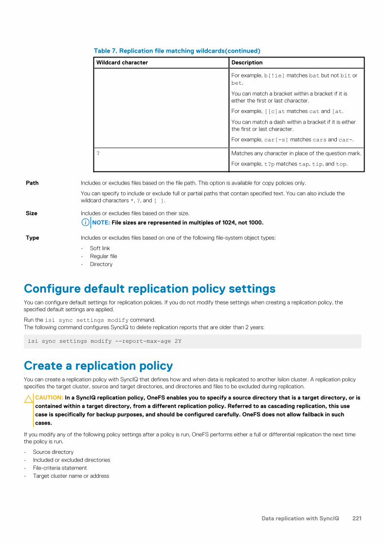
Table 7. Replication file matching wildcards(continued)
Wildcard character Description
For example, b[!ie] matches bat but not bit orbet.
You can match a bracket within a bracket if it iseither the first or last character.
For example, [[c]at matches cat and [at.
You can match a dash within a bracket if it is eitherthe first or last character.
For example, car[-s] matches cars and car-.
? Matches any character in place of the question mark.
For example, t?p matches tap, tip, and top.
Path Includes or excludes files based on the file path. This option is available for copy policies only.
You can specify to include or exclude full or partial paths that contain specified text. You can also include thewildcard characters *, ?, and [ ].
Size Includes or excludes files based on their size.
NOTE: File sizes are represented in multiples of 1024, not 1000.
Type Includes or excludes files based on one of the following file-system object types:
• Soft link• Regular file• Directory
Configure default replication policy settingsYou can configure default settings for replication policies. If you do not modify these settings when creating a replication policy, thespecified default settings are applied.
Run the isi sync settings modify command.The following command configures SyncIQ to delete replication reports that are older than 2 years:
isi sync settings modify --report-max-age 2Y
Create a replication policyYou can create a replication policy with SyncIQ that defines how and when data is replicated to another Isilon cluster. A replication policyspecifies the target cluster, source and target directories, and directories and files to be excluded during replication.
CAUTION: In a SyncIQ replication policy, OneFS enables you to specify a source directory that is a target directory, or is
contained within a target directory, from a different replication policy. Referred to as cascading replication, this use
case is specifically for backup purposes, and should be configured carefully. OneFS does not allow failback in such
cases.
If you modify any of the following policy settings after a policy is run, OneFS performs either a full or differential replication the next timethe policy is run.
• Source directory• Included or excluded directories• File-criteria statement• Target cluster name or address
Data replication with SyncIQ 221

This applies only if you modify a replication policy to specify a different target cluster. If you modify the IP or domain name of a targetcluster, and then modify the replication policy on the source cluster to match the new IP or domain name, a full replication is notperformed. Note also that SyncIQ does not support dynamically allocated IP address pools. If a replication job connects to adynamically allocated IP address, SmartConnect might reassign the address while a replication job is running, which would cause thejob to fail.
• Target directoryNOTE: If you create a replication policy for a SmartLock compliance directory, the SyncIQ and SmartLock
compliance domains must be configured at the same root directory level. A SmartLock compliance directory cannot
be nested inside a SyncIQ directory.
Run the isi sync policies create command.
The following command creates a policy that replicates the directory /ifs/data/source on the source cluster to /ifs/data/target on target cluster 10.1.99.36 every week. The command also creates archival snapshots on the target cluster:
isi sync policies create mypolicy sync /ifs/data/source 10.1.99.36 /ifs/data/target --schedule "Every Sunday at 12:00 AM" --target-snapshot-archive on --target-snapshot-expiration 1Y--target-snapshot-pattern "%{PolicyName}-%{SrcCluster}-%Y-%m-%d
Create a SyncIQ domainYou can create a SyncIQ domain to increase the speed at which failback is performed for a replication policy. Because you can fail backonly synchronization policies, it is not necessary to create SyncIQ domains for copy policies.
Failing back a replication policy requires that a SyncIQ domain be created for the source directory. OneFS automatically creates a SyncIQdomain during the failback process. However, if you intend on failing back a replication policy, it is recommended that you create a SyncIQdomain for the source directory of the replication policy while the directory is empty. Creating a domain for a directory that contains lessdata takes less time.
Run the isi job jobs start command.The following command creates a SyncIQ domain for /ifs/data/source:
isi job jobs start DomainMark --root /ifs/data/media \--dm-type SyncIQ
Assess a replication policyBefore running a replication policy for the first time, you can view statistics on the files that would be affected by the replication withouttransferring any files. This can be useful if you want to preview the size of the data set that will be transferred if you run the policy.
You can assess only replication policies that have never been run before.
1. Run the isi sync jobs start command with the --test option.The following command creates a report about how much data will be transferred when a sync job named weeklySync is run:
isi sync jobs start weeklySync --test2. To view the assessment report, run the isi sync reports view command.
The following command displays the assessment report for weeklySync:
isi sync reports view weeklySync 1
Managing replication to remote clustersYou can manually run, view, assess, pause, resume, cancel, resolve, and reset replication jobs that target other clusters.
After a policy job starts, you can pause the job to suspend replication activities. Afterwards, you can resume the job, continuing replicationfrom the point where the job was interrupted. You can also cancel a running or paused replication job if you want to free the clusterresources allocated for the job. A paused job reserves cluster resources whether or not the resources are in use. A cancelled job releasesits cluster resources and allows another replication job to consume those resources. No more than five running and paused replication jobscan exist on a cluster at a time. However, an unlimited number of canceled replication jobs can exist on a cluster. If a replication jobremains paused for more than a week, SyncIQ automatically cancels the job.
222 Data replication with SyncIQ

Start a replication jobYou can manually start a replication job for a replication policy at any time. You can also replicate data according to a snapshot created bySnapshotIQ. You cannot replicate data according to a snapshot generated by SyncIQ.
Run the isi sync jobs start command.The following command starts weeklySync:
isi sync jobs start weeklySync
The following command replicates the source directory of weeklySync according to the snapshot HourlyBackup_07-15-2013_23:00:
isi sync jobs start weeklySync \--source-snapshot HourlyBackup_07-15-2013_23:00
Pause a replication jobYou can pause a running replication job and then resume the job later. Pausing a replication job temporarily stops data from beingreplicated, but does not free the cluster resources replicating the data.
Run the isi sync jobs pause command.The following command pauses weeklySync:
isi sync jobs pause weeklySync
Resume a replication jobYou can resume a paused replication job.
Run the isi sync jobs resume command.The following command resumes weeklySync:
isi sync jobs resume weeklySync
Cancel a replication jobYou can cancel a running or paused replication job. Cancelling a replication job stops data from being replicated and frees the clusterresources that were replicating data. You cannot resume a cancelled replication job; to restart replication, you must start the replicationpolicy again.
Run the isi sync jobs cancel command.The following command cancels weeklySync:
isi sync jobs cancel weeklySync
View active replication jobsYou can view information about replication jobs that are currently running or paused.
1. View all active replication jobs by running the following command:
isi sync jobs list2. To view detailed information about a specific replication job, run the isi sync jobs view command.
The following command displays detailed information about a replication job created by weeklySync:
isi sync jobs view weeklySync
The system displays output similar to the following example:
Policy Name: weeklySync ID: 3
Data replication with SyncIQ 223

State: running Action: run Duration: 5s Start Time: 2013-07-16T23:12:00
Replication job informationYou can view information about replication jobs.
The following information is displayed in the output of the isi snapshot settings view command:
Policy Name The name of the associated replication policy.
ID The ID of the replication job.
State The status of the job.
Action The type of replication policy.
Initiating data failover and failback with SyncIQYou can fail over from one Isilon cluster to another if, for example, your primary cluster becomes unavailable. You can fail back when theprimary cluster becomes available again. You can revert failover if you decide that the failover was unnecessary, or if you failed over fortesting purposes.
NOTE: Data failover and failback are now supported for both compliance SmartLock directories and enterprise
SmartLock directories. Compliance SmartLock directories can be created only on clusters that have been set up as
compliance mode clusters during initial configuration.
Fail over data to a secondary clusterYou can fail over to a secondary Isilon cluster if, for example, your primary cluster becomes unavailable.
You must have created and successfully run a replication policy on the primary cluster. This action replicated data to the secondarycluster.
NOTE: Data failover is supported both for compliance and enterprise SmartLock directories. SmartLock compliance
directories require their own replication policies. Such directories cannot be nested inside non-compliance directories
and replicated as part of an overall policy.
Complete the following procedure for each replication policy that you want to fail over.
1. If your primary cluster is still online, complete the following steps:
a. Stop all writes to the replication policy's path, including both local and client activity.
This action ensures that new data is not written to the policy path as you prepare for failover to the secondary cluster.
b. Modify the replication policy so that it is set to run only manually.
This action prevents the policy on the primary cluster from automatically running a replication job. If the policy on the primarycluster runs a replication job while writes are allowed to the target directory, the job fails and the replication policy is deactivated. Ifthis happens, modify the policy so that it is set to run only manually, resolve the policy, and complete the failback process. Afteryou complete the failback process, you can modify the policy to run according to a schedule again.
The following command ensures that the policy weeklySync runs only manually:
isi sync policies modify weeklySync --schedule ""2. On the secondary cluster, run the isi sync recovery allow-write command.
The following command enables replicated directories and files specified in the weeklySync policy to be writable:
isi sync recovery allow-write weeklySync
NOTE: SmartLock compliance mode WORM files, although replicated, are stored in a non-writable, non-erasable
format.
3. Direct your users to the secondary cluster for data access and normal operations.
224 Data replication with SyncIQ

Revert a failover operationFailover reversion undoes a failover operation on a secondary cluster, enabling you to replicate data from the primary cluster to thesecondary cluster again. Failover reversion is useful if the primary cluster becomes available before data is modified on the secondarycluster or if you failed over to a secondary cluster for testing purposes.
Fail over a replication policy.
Reverting a failover operation does not migrate modified data back to the primary cluster. To migrate data that clients have modified onthe secondary cluster, you must fail back to the primary cluster.
NOTE:
Failover reversion is not supported for SmartLock directories.
Complete the following procedure for each replication policy that you want to fail over.
Run the isi sync recovery allow-write command with the --revert option.For example, the following command reverts a failover operation for newPolicy:
isi sync recovery allow-write newPolicy --revert
Fail back data to a primary clusterAfter you fail over to a secondary cluster, you can fail back to the primary cluster.
Before you can fail back to the primary cluster, you must already have failed over to the secondary cluster. Also, you must ensure thatyour primary cluster is back online.
1. Create mirror policies on the secondary cluster by running the isi sync recovery resync-prep command on the primarycluster.The following command creates a mirror policy for weeklySync:
isi sync recovery resync-prep weeklySync
SyncIQ names mirror policies according to the following pattern:
<replication-policy-name>_mirror
2. Before beginning the failback process, prevent clients from accessing the secondary cluster.
This action ensures that SyncIQ fails back the latest data set, including all changes that users made to data on the secondary clusterwhile the primary cluster was out of service. We recommend that you wait until clients are inactive before preventing access to thesecondary cluster.
3. On the secondary cluster, run the isi sync jobs start command to run the mirror policy and replicate data to the primarycluster.The following command runs a mirror policy named weeklySync_mirror immediately:
isi sync jobs start weeklySync_mirror
Alternatively, you can modify the mirror policy to run on a particular schedule. The following command schedules a mirror policy namedweeklySync_mirror to run daily at 12:01 AM:
isi sync policies modify weeklySync_mirror --enabled yes --schedule "every day at 12:01 AM"
If specifying a schedule for the mirror policy, you need only allow the mirror policy to run once at the scheduled time. After that, youshould set the mirror policy back to a manual schedule.
4. On the primary cluster, allow writes to the target directories of the mirror policy by running the isi sync recovery allow-write command.The following command allows writes to the directories specified in the weeklySync_mirror policy:
isi sync recovery allow-write weeklySync_mirror5. On the secondary cluster, complete the failback process by running the isi sync recovery resync-prep command for the
mirror policy.
Data replication with SyncIQ 225

The following command completes the failback process for weeklySync_mirror by placing the secondary cluster back into read-only mode and ensuring that the data sets are consistent on both the primary and secondary clusters. :
isi sync recovery resync-prep weeklySync_mirror
Direct clients back to the primary cluster for normal operations. Although not required, it is safe to remove a mirror policy after failback hascompleted successfully.
Run the ComplianceStoreDelete job in a Smartlockcompliance mode domainSyncIQ handles conflicts during failover/failback operations on a SmartLock compliance mode domain by unlinking committed files fromthe user store and leaving a link of the file in the compliance store. The ComplianceStoreDelete job automatically tracks and removesexpired files from the compliance store if they were put there as a result of SyncIQ conflict resolution.
For example, you perform a SyncIQ failover or failback on a SmartLock compliance mode domain. The operation results in a committed filebeing reverted to an uncommitted state. For conflict resolution, a copy of the committed file is stored in the compliance store. Thecommitted file in the compliance store eventually expires. The ComplianceStoreDelete job runs automatically once a month and deletesthe expired file. Expired files that are in use (referenced from outside of compliance store) will not be deleted.
The ComplianceStoreDelete job runs automatically once per month or when started manually. You can run the job manually from the CLI.
Run the isi job jobs start ComplianceStoreDelete command.
Performing disaster recovery for older SmartLockdirectoriesIf you replicated a SmartLock compliance directory to a secondary cluster running OneFS 7.2.1 or earlier, you cannot fail back theSmartLock compliance directory to a primary cluster running OneFS 8.0.1 or later. However, you can recover the SmartLock compliancedirectory stored on the secondary cluster, and migrate it back to the primary cluster.
NOTE: Data failover and failback with earlier versions of OneFS are supported for SmartLock enterprise directories.
Recover SmartLock compliance directories on a targetclusterYou can recover compliance SmartLock directories that you have replicated to a secondary cluster running OneFS 7.2.1 or earlier versions.
Complete the following procedure for each SmartLock directory that you want to recover.
1. On the secondary cluster, enable writes to the SmartLock directories that you want to recover.
• If the last replication job completed successfully and a replication job is not currently running, run the isi sync recoveryallow-write command on the secondary cluster.
For example, the following command enables writes to the target directory of SmartLockSync:
isi sync recovery allow-write SmartLockSync• If a replication job is currently running, wait until the replication job completes, and then run the isi sync recovery allow-
write command.
• If the primary cluster became unavailable while a replication job was running, run the isi sync target break command.Note that you should only break the association if the primary cluster has been taken offline permanently.
For example, the following command breaks the association for the target directory of SmartLockSync:
isi sync target break SmartLockSync2. If you ran isi sync target break, restore any files that are left in an inconsistent state.
a. Delete all files that are not committed to a WORM state from the target directory.b. Copy all files from the failover snapshot to the target directory.
Failover snapshots are named according to the following naming pattern:
226 Data replication with SyncIQ

SIQ-Failover-<policy-name>-<year>-<month>-<day>_<hour>-<minute>-<second>Snapshots are located under the hidden directory /ifs/.snapshot.
3. If any SmartLock directory configuration settings, such as an autocommit time period, were specified for the source directory of thereplication policy, apply those settings to the target directory.Because autocommit information is not transferred to the target cluster, files that were scheduled to be committed to a WORM stateon the source cluster would not be scheduled to be committed at the same time on the target cluster. To ensure that all files areretained for the appropriate time period, you can commit all files in target SmartLock directories to a WORM state. For example, thefollowing command automatically commits all files in /ifs/data/smartlock to a WORM state after one minute.
isi worm domains modify --domain /ifs/data/smartlock--autocommit-offset 1m
Migrate SmartLock compliance directoriesYou can migrate SmartLock compliance directories from a recovery cluster, either by replicating the directories back to the original sourcecluster, or to a new cluster. Migration is necessary only when the recovery cluster is running OneFS 7.2.1 or earlier. These OneFS versionsdo not support failover and failback of SmartLock compliance directories.
1. On the recovery cluster, create a replication policy for each SmartLock compliance directory that you want to migrate to anothercluster (the original primary cluster or a new cluster).
The policies must meet the following requirements:
• The source directory on the recovery cluster is the SmartLock compliance directory that you are migrating.• The target directory is an empty SmartLock compliance directory on the cluster to which the data is to be migrated. The source
and target directories must both be SmartLock compliance directories.
2. Replicate recovery data to the target directory by running the policies that you created.
You can replicate data either by manually starting the policy or by specifying a policy schedule.
3. Optional: To ensure that SmartLock protection is enforced for all files, commit all migrated files in the SmartLock target directory to aWORM state.
Because autocommit information is not transferred from the recovery cluster, commit all migrated files in target SmartLock directoriesto a WORM state.
For example, the following command automatically commits all files in /ifs/data/smartlock to a WORM state after one minute:
isi worm domains modify --domain /ifs/data/smartlock \--autocommit-offset 1m
This step is necessary only if you have not configured an autocommit time period for the SmartLock directory.
4. On the target cluster, enable writes to the replication target directories by running the isi sync recovery allow-writescommand.For example, the following command enables writes to the SmartLockSync target directory:
isi sync recovery allow-writes SmartLockSync5. If any SmartLock directory configuration settings, such as an autocommit time period, were specified for the source directories of the
replication policies, apply those settings to the target directories.6. Delete the copy of the SmartLock data on the recovery cluster.
You cannot recover the space consumed by the source SmartLock directories until all files are released from a WORM state. If youwant to free the space before files are released from a WORM state, contact Isilon Technical Support for information aboutreformatting your recovery cluster.
Managing replication policiesYou can modify, view, enable, and disable replication policies.
Data replication with SyncIQ 227

Modify a replication policyYou can modify the settings of a replication policy.
If you modify any of the following policy settings after the policy runs, OneFS performs either a full or differential replication the next timethe policy runs:
• Source directory• Included or excluded directories• File-criteria statement• Target cluster
This applies only if you target a different cluster. If you modify the IP or domain name of a target cluster, and then modify thereplication policy on the source cluster to match the new IP or domain name, a full replication is not performed.
• Target directory
Run the isi sync policies modify command.Assuming that weeklySync has been reset and has not been run since it was reset, the following command causes a differential replicationto be performed the next time weeklySync is run:
isi sync policies modify weeklySync--target-compare-initial-sync=true
Delete a replication policyYou can delete a replication policy. Once a policy is deleted, SyncIQ no longer creates replication jobs for the policy. Deleting a replicationpolicy breaks the target association on the target cluster, and allows writes to the target directory.
If you want to temporarily suspend a replication policy from creating replication jobs, you can disable the policy, and then enable the policyagain later.
Run the isi sync policies delete command.The following command deletes weeklySync from the source cluster and breaks the target association on the target cluster:
isi sync policies delete weeklySync
NOTE: The operation will not succeed until SyncIQ can communicate with the target cluster; until then, the policy will
still appear in the output of the isi sync policies list command. After the connection between the source cluster
and target cluster is reestablished, SyncIQ will delete the policy the next time that the job is scheduled to run; if the
policy is configured to run only manually, you must manually run the policy again. If SyncIQ is permanently unable to
communicate with the target cluster, run the isi sync policies delete command with the --local-only option.
This will delete the policy from the local cluster only and not break the target association on the target cluster.
Enable or disable a replication policyYou can temporarily suspend a replication policy from creating replication jobs, and then enable it again later.
NOTE: If you disable a replication policy while an associated replication job is running, the running replication job is not
interrupted. However, the policy will not create another job until the policy is enabled.
Run either the isi sync policies enable or the isi sync policies disable command.The following command enables weeklySync:
isi sync policies enable weeklySync
The following command disables weeklySync:
isi sync policies disable weeklySync
228 Data replication with SyncIQ

View replication policiesYou can view information about replication policies.
1. View information about all replication policies by running the following command:
isi sync policies list2. Optional: To view detailed information about a specific replication policy, run the isi sync policies view command.
The following command displays detailed information about weeklySync:
isi sync policies view weeklySync
The system displays output similar to the following example:
ID: dd16d277ff995a78e9affbba6f6e2919 Name: weeklySync Path: /ifs/data/archive Action: sync Enabled: No Target: localhost Description: Check Integrity: Yes Source Include Directories: - Source Exclude Directories: - Source Subnet: - Source Pool: - Source Match Criteria: Target Path: /ifs/data/sometarget Target Snapshot Archive: No Target Snapshot Pattern: SIQ-%{SrcCluster}-%{PolicyName}-%Y-%m-%d_%H-%M-%S Target Snapshot Expiration: Never Target Snapshot Alias: SIQ-%{SrcCluster}-%{PolicyName}-latestTarget Detect Modifications: Yes Source Snapshot Archive: No Source Snapshot Pattern: Source Snapshot Expiration: Never Schedule: Manually scheduled Log Level: notice Log Removed Files: No Workers Per Node: 3 Report Max Age: 2Y Report Max Count: 2000 Force Interface: No Restrict Target Network: NoTarget Compare Initial Sync: No Disable Stf: No Disable Fofb: No Resolve: - Last Job State: finished Last Started: 2013-07-17T15:39:49 Last Success: 2013-07-17T15:39:49 Password Set: No Conflicted: No Has Sync State: Yes
Replication policy informationYou can view information about replication policies through the output of the isi sync policies list command.
Name The name of the policy.
Path The path of the source directory on the source cluster.
Action The type of replication policy.
Enabled Whether the policy is enabled or disabled.
Target The IP address or fully qualified domain name of the target cluster.
Data replication with SyncIQ 229
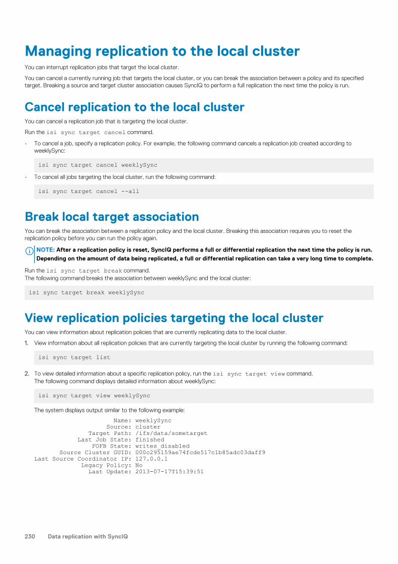
Managing replication to the local clusterYou can interrupt replication jobs that target the local cluster.
You can cancel a currently running job that targets the local cluster, or you can break the association between a policy and its specifiedtarget. Breaking a source and target cluster association causes SyncIQ to perform a full replication the next time the policy is run.
Cancel replication to the local clusterYou can cancel a replication job that is targeting the local cluster.
Run the isi sync target cancel command.
• To cancel a job, specify a replication policy. For example, the following command cancels a replication job created according toweeklySync:
isi sync target cancel weeklySync• To cancel all jobs targeting the local cluster, run the following command:
isi sync target cancel --all
Break local target associationYou can break the association between a replication policy and the local cluster. Breaking this association requires you to reset thereplication policy before you can run the policy again.
NOTE: After a replication policy is reset, SyncIQ performs a full or differential replication the next time the policy is run.
Depending on the amount of data being replicated, a full or differential replication can take a very long time to complete.
Run the isi sync target break command.The following command breaks the association between weeklySync and the local cluster:
isi sync target break weeklySync
View replication policies targeting the local clusterYou can view information about replication policies that are currently replicating data to the local cluster.
1. View information about all replication policies that are currently targeting the local cluster by running the following command:
isi sync target list
2. To view detailed information about a specific replication policy, run the isi sync target view command.The following command displays detailed information about weeklySync:
isi sync target view weeklySync
The system displays output similar to the following example:
Name: weeklySync Source: cluster Target Path: /ifs/data/sometarget Last Job State: finished FOFB State: writes_disabled Source Cluster GUID: 000c295159ae74fcde517c1b85adc03daff9Last Source Coordinator IP: 127.0.0.1 Legacy Policy: No Last Update: 2013-07-17T15:39:51
230 Data replication with SyncIQ

Remote replication policy informationYou can view information about replication policies that are currently targeting the local cluster through the output of the isi synctarget list command.
Name The name of the replication policy.
Source The name of the source cluster.
Target Path The path of the target directory on the target cluster.
Last Job State The state of the most recent replication job for the policy.
FOFB State The failover-failback state of the target directory.
Managing replication performance rulesYou can manage the impact of replication on cluster performance by creating rules that limit the network traffic created and the rate atwhich files are sent by replication jobs.
Create a network traffic ruleYou can create a network traffic rule that limits the amount of network traffic that replication policies are allowed to generate during aspecified time period.
Run the isi sync rules create command.The following command creates a network traffic rule that limits bandwidth consumption to 100 KB per second from 9:00 AM to 5:00 PMevery weekday:
isi sync rules create bandwidth 9:00-17:00 M-F 100
Create a file operations ruleYou can create a file-operations rule that limits the number of files that replication jobs can send per second.
Run the isi sync rules create command.The following command creates a file-operations rule that limits the file-send rate to 3 files per second from 9:00 AM to 5:00 PM everyweekday: :
isi sync rules create file_count 9:00-17:00 M-F 3
Modify a performance ruleYou can modify a performance rule.
1. Optional: To identify the ID of the performance rule you want to modify, run the following command:
isi sync rules list2. Modify a performance rule by running the isi sync rules modify command.
The following command causes a performance rule with an ID of bw-0 to be enforced only on Saturday and Sunday:
isi sync rules modify bw-0 --days X,S
Delete a performance ruleYou can delete a performance rule.
1. Optional: To identify the ID of the performance rule you want to modify, run the following command:
isi sync rules list
Data replication with SyncIQ 231

2. Delete a performance rule by running the isi sync rules delete command.The following command deletes a performance rule with an ID of bw-0:
isi sync rules delete bw-0
Enable or disable a performance ruleYou can disable a performance rule to temporarily prevent the rule from being enforced. You can also enable a performance rule after ithas been disabled.
1. Optional: To identify the ID of the performance rule you want to enable or disable, run the following command:
isi sync rules list
2. Run the isi sync rules modify command.The following command enables a performance rule with an ID of bw-0:
isi sync rules modify bw-0 --enabled true
The following command disables a performance rule with an ID of bw-0:
isi sync rules modify bw-0 --enabled false
View performance rulesYou can view performance rules.
1. View information about all performance rules by running the following command:
isi sync rules list
2. Optional: To view detailed information about a specific performance rule, run the isi sync rules view command.The following command displays detailed information about a performance rule with an ID of bw-0:
isi sync rules view --id bw-0
The system displays output similar to the following example:
ID: bw-0 Enabled: Yes Type: bandwidth Limit: 100 kbps Days: Sun,Sat Schedule Begin : 09:00 End : 17:00Description: Bandwidth rule for weekdays
Managing replication reportsIn addition to viewing replication reports, you can configure how long reports are retained on the cluster. You can also delete any reportsthat have passed their expiration period.
Configure default replication report settingsYou can configure the default amount of time that SyncIQ retains replication reports for. You can also configure the maximum number ofreports that SyncIQ retains for each replication policy.
Run the isi sync settings modify command.The following command causes OneFS to delete replication reports that are older than 2 years:
isi sync settings modify --report-max-age 2Y
232 Data replication with SyncIQ

Delete replication reportsReplication reports are routinely deleted by SyncIQ after the expiration date for the reports has passed. SyncIQ also deletes reports afterthe number of reports exceeds the specified limit. Excess reports are periodically deleted by SyncIQ; however, you can manually delete allexcess replication reports at any time. This procedure is available only through the command-line interface (CLI).
1. Open a secure shell (SSH) connection to any node in the cluster, and log in.2. Delete excess replication reports by running the following command:
isi sync reports rotate
View replication reportsYou can view replication reports and subreports.
1. View a list of all replication reports by running the following command:
isi sync reports list2. View a replication report by running the isi sync reports view command.
The following command displays a replication report for weeklySync:
isi sync reports view weeklySync 23. Optional: To view a list of subreports for a report, run the isi sync reports subreports list command.
The following command displays subreports for weeklySync:
isi sync reports subreports list weeklySync 14. Optional: To view a subreport, run the isi sync reports subreports view command.
The following command displays a subreport for weeklySync:
isi sync reports subreports view weeklySync 1 2
The system displays output similar to the following example:
Policy Name: weeklySync Job ID: 1 Subreport ID: 2 Start Time: 2013-07-17T21:59:10 End Time: 2013-07-17T21:59:15 Action: run State: finished Policy ID: a358db8b248bf432c71543e0f02df64e Sync Type: initial Duration: 5s Errors: - Source Directories Visited: 0 Source Directories Deleted: 0 Target Directories Deleted: 0 Source Directories Created: 0 Target Directories Created: 0 Source Directories Linked: 0 Target Directories Linked: 0 Source Directories Unlinked: 0 Target Directories Unlinked: 0 Num Retransmitted Files: 0 Retransmitted Files: - Total Files: 0 Files New: 0 Source Files Deleted: 0 Files Changed: 0 Target Files Deleted: 0 Up To Date Files Skipped: 0 User Conflict Files Skipped: 0 Error Io Files Skipped: 0 Error Net Files Skipped: 0Error Checksum Files Skipped: 0 Bytes Transferred: 245
Data replication with SyncIQ 233

Total Network Bytes: 245 Total Data Bytes: 20 File Data Bytes: 20 Sparse Data Bytes: 0 Target Snapshots: SIQ-Failover-newPol123-2013-07-17_21-59-15, newPol123-Archive-cluster-17 Total Phases: 2 Phases Phase : STF_PHASE_IDMAP_SEND Start Time : 2013-07-17T21:59:11 End Time : 2013-07-17T21:59:13
Replication report informationYou can view information about replication jobs through the Reports table.
Policy Name The name of the associated policy for the job. You can view or edit settings for the policy by clicking the policyname.
Status Displays the status of the job. The following job statuses are possible:Running
The job is currently running without error.
Paused
The job has been temporarily paused.
Finished
The job completed successfully.
Failed
The job failed to complete.
Started Indicates when the job started.
Ended Indicates when the job ended.
Duration Indicates how long the job took to complete.
Transferred The total number of files that were transferred during the job run, and the total size of all transferred files. Forassessed policies, Assessment appears.
Source Directory The path of the source directory on the source cluster.
Target Host The IP address or fully qualified domain name of the target cluster.
Action Displays any report-related actions that you can perform.
Managing failed replication jobsIf a replication job fails due to an error, SyncIQ might disable the corresponding replication policy. For example SyncIQ might disable areplication policy if the IP or hostname of the target cluster is modified. If a replication policy is disabled, the policy cannot be run.
To resume replication for a disabled policy, you must either fix the error that caused the policy to be disabled, or reset the replicationpolicy. It is recommended that you attempt to fix the issue rather than reset the policy. If you believe you have fixed the error, you canreturn the replication policy to an enabled state by resolving the policy. You can then run the policy again to test whether the issue wasfixed. If you are unable to fix the issue, you can reset the replication policy. However, resetting the policy causes a full or differentialreplication to be performed the next time the policy is run.
NOTE: Depending on the amount of data being synchronized or copied, full and differential replications can take a very
long time to complete.
234 Data replication with SyncIQ

Resolve a replication policyIf SyncIQ disables a replication policy due to a replication error, and you fix the issue that caused the error, you can resolve the replicationpolicy. Resolving a replication policy enables you to run the policy again. If you cannot resolve the issue that caused the error, you canreset the replication policy.
Run the isi sync policies resolve command.The following command resolves weeklySync:
isi sync policies resolve weeklySync
Reset a replication policyIf a replication job encounters an error that you cannot resolve, you can reset the corresponding replication policy. Resetting a policycauses OneFS to perform a full or differential replication the next time the policy is run.
Resetting a replication policy deletes the source-cluster snapshot.
NOTE: Depending on the amount of data being replicated, a full or differential replication can take a very long time to
complete. Reset a replication policy only if you cannot fix the issue that caused the replication error. If you fix the issue
that caused the error, resolve the policy instead of resetting the policy.
Run the isi sync policies reset command.The following command resets weeklySync:
isi sync policies reset weeklySync
Perform a full or differential replicationAfter you reset a replication policy, you must perform either a full or differential replication. You can do this only from the CLI.
Reset a replication policy.
1. Open a secure shell (SSH) connection to any node in the cluster and log in through the root or compliance administrator account.2. Specify the type of replication you want to perform by running the isi sync policies modify command.
• To perform a full replication, disable the --target-compare-initial-sync option.
For example, the following command disables differential synchronization for newPolicy:
isi sync policies modify newPolicy \--target-compare-initial-sync false
• To perform a differential replication, enable the --target-compare-initial-sync option.
For example, the following command enables differential synchronization for newPolicy:
isi sync policies modify newPolicy \--target-compare-initial-sync true
3. Run the policy by running the isi sync jobs start command.For example, the following command runs newPolicy:
isi sync jobs start newPolicy
Data replication with SyncIQ 235

Data Encryption with SyncIQThis section contains the following topics:
Topics:
• SyncIQ data encryption overview• SyncIQ traffic encryption• Per-policy throttling overview• Troubleshooting SyncIQ encryption
SyncIQ data encryption overviewOneFS now enables you to encrypt SyncIQ data from one Isilon cluster to another.
You can use the integrated capabilities of SyncIQ to encrypt the data during transfer between Isilon clusters and protect the data in flightduring intercluster replications. It is recommended that you use encryption or a pre-shared key (PSK) when using SyncIQ . See article542907 for more information.
SyncIQ policies now support end-to-end encryption for cross-cluster communications.
You can easily manage certificates with the help of the new SyncIQ store. Certification revocation is supported through an external OnlineCertificate Status Protocol (OCSP) responder.
Isilon clusters may now require that all incoming and outgoing SyncIQ policies be encrypted through a simple change in the SyncIQ GlobalSettings.
SyncIQ traffic encryptionSyncIQ data that is transmitted between the source and target clusters is encrypted.
SyncIQ provides additional protection from man-in-the-middle attacks and prevents unauthorized source or target relationships. Thestandard certificate configuration for SyncIQ policy encryption requires six files:
• SourceClusterCert.pem - A single end-entity certificate that identifies the Source cluster• SourceClusterKey.pem - The associated private key file that goes with the Source cluster identity cert• SourceClusterCA.pem - A self-signed root CA file that issued the Source cluster identity cert• TargetClusterCert.pem - A single end-entity certificate that identifies the Target cluster• TargetClusterKey.pem - The associated private key file that goes with the Target cluster identity cert• TargetClusterCA.pem - A self-signed root CA file that issued the Target cluster identity cert (may be the same as 3)
Because SyncIQ encryption requires mutual authentication SSL handshakes, each cluster must specify its own identity certificate and theCA certificate of the peer.
Configure certificatesYou can configure certificates for SyncIQ policy encryption.
1. On the Source cluster, install the identity certificate and private key pair to the server certificate store.
isi sync cert server import SourceClusterCert.pem SourceClusterKey.pem --certificate-key-password <string> --name myClusterCertID
2. On the Source cluster, set the newly installed ID from the server store as your SyncIQ cluster certificate. The full ID of the certificate isdisplayed when the -v option is used to the server store list command.
isi sync cert server list -v isi sync setting mod –cluster-certificate-id=<fullID>
18
236 Data Encryption with SyncIQ

3. On the Source cluster, install the Source cluster CA to the global cluster CA store. This CA was used to issue TargetClusterCert.pem.
isi cert auth import TargetClusterCA.pem --name SyncIQTargetCA4. On the Source cluster, add the Target’s certificate to the whitelist peer certificate store.
isi sync cert peer import TargetClusterCert.pem --name SyncIQTargetClusterCert
NOTE: This step requires the end-entity certificate for each SyncIQ peer be shared with the peer. This action is not
an SSL requirement. It is an implementation specific requirement to add a whitelist layer of security to SyncIQ
encryption policies. The associated private key for peer certificates should not be shared when exchanging end-
entity certificates with peers.
5. On the Target cluster, install the identity certificate and private key pair to the server certificate store.
isi sync cert server import TargetClusterCert.pem TargetClusterKey.pem --certificate-key-password<string> --name myClusterCertID
6. On the Target cluster, set the newly installed ID from the server store as your SyncIQ cluster certificate. The full ID of the certificate isdisplayed when the -v option is used to the server store list command.
isi sync cert server list -v isi sync setting mod –cluster-certificate-id=<fullID>
7. On the Target cluster, install the Source cluster CA to the global cluster CA store. This CA that was used to issueSourceClusterCert.pem.
isi cert auth import SourceClusterCA.pem --name SyncIQSourceCA8. On the Target cluster, add the Source's certificate to the whitelist peer certificate store.
isi sync cert peer import SourceClusterCert.pem --name SyncIQSourceClusterCert
NOTE: This step requires the end-entity certificate for each SyncIQ peer be shared with the peer. This action is not
an SSL requirement. It is an implementation specific requirement to add a whitelist layer of security to SyncIQ
encryption policies. The associated private key for peer certificates should not be shared when exchanging end-
entity certificates with peers.
Create encrypted SyncIQ policiesYou can create encrypted SyncIQ policies.
1. To enable encryption, associate the target certificate ID with the policy. The nominated certificate is used as the whitelist check duringthe sync job. You can see the full ID for a certificate when the -v option is used in the certificate list command.
isi sync cert peer list -v isi sync pol create foo sync /ifs/syncDir <targetIP> /ifs/syncDir –target-certificate-id=<targetFullID>
2. Optionally, force all SyncIQ policies to require encryption.
isi sync setting mod --encryption-required=True
Per-policy throttling overviewOneFS now enables you to set per-policy throttling rules.
Existing versions of OneFS enables you to configure global bandwidth throttling rules that are applied evenly across running policies. Now,you can set bandwidth reservations per policy, instead of the global level.
Data Encryption with SyncIQ 237

Create a bandwidth ruleYou can create a bandwidth rule for SyncIQ and configure policy-level reservation.
1. License SyncIQ and create one or more policies.2. Create a bandwidth rule for SyncIQ.
isi sync rules create bandwidth --limit=1000 00:00-23:59 M-F3. Configure policy-level reservation.
isi sync policies modify test --bandwidth-reservation=500
Troubleshooting SyncIQ encryptionIf you are unable to configure the SyncIQ encryption, check the report of the SyncIQ policy in question and follow the troubleshooting tipsgiven below to fix the issue.
• If the failure is due to a Transport Layer Security (TLS) authentication failure, you can find the error message from TLS library in thereport.
• If it is a TLS authentication failure, detailed information can be found at /var/log/messages on the source and target clusters. Thedetailed information includes:
○ The ID of the certificate that caused the failure○ The subject name of the certificate that caused the failure○ The depth at which the failure occurred in the certification chain○ The error code and the reason for the failure
238 Data Encryption with SyncIQ

Data Compression
Data compressionIsilon F810 nodes allow you to perform in-line data compression on your Isilon cluster.
OneFS supports in-line data compression on Isilon F810 node pools only. F810 nodes contain Network Interface Cards (NICs) thatcompress and decompress data received by the node.
Hardware compression and decompression is performed in parallel across the 40Gb Ethernet interfaces of F810 nodes as clients read andwrite data to the cluster. This distributed interface model allows compression to scale linearly across the all-flash F810 node pool as anIsilon cluster grows and additional F810 nodes are added.
You can enable in-line data compression on a cluster that:
• contains an F810 node pool• offers a 40Gb Ethernet back-end network• is running OneFS 8.1.3 or OneFS 8.2.1 and later releases
Mixed ClustersIn a mixed cluster containing node types other than the F810, files will only be stored in a compressed form on F810 node pools. Data thatis written or tiered to storage pools of other node types will be uncompressed when it moves between pools.
Data compression settings and monitoringFrom the OneFS command line, you can enable and disable in-line data compression on an Isilon cluster. You can also view statisticsrelated to compression activity and efficiency across the cluster.
Data compression is only available with node pools of F810 nodes.
Enable or disable data compressionYou can turn data compression on or off from the OneFS command line.
This procedure is available only through the OneFS command-line interface (CLI).
There are only two possible settings for data compression configuration and those are either Enabled: yes or Enabled: no. Thedefault setting is Enabled: yes.
NOTE: This compression setting only applies to data stored on F810 node pools. Data written to any node type other
than F810s will ignore this setting and will not be compressed. If a cluster does not contain an F810 node pool, this
setting is ignored.
NOTE: When you enable compression, OneFS will not go back and compress the data that was written while
compression was disabled.
1. To view the current compression setting, run the following command:
isi compression settings viewThe system displays output similar to the following example:
Enabled: Yes
2. If compression is enabled and you want to disable it, run the following command:
isi compression settings modify --enabled=False3. If compression is disabled and you want to enable it, run the following command:
19
Data Compression 239

isi compression settings modify --enabled=True4. After you adjust settings, confirm that the setting is correct. Run the following command:
isi compression settings view
View compression statisticsYou can view reports related to compression that include information such as current and historic compression ratios, as well as logical andphysical data block totals.
This procedure is available only through the OneFS command-line interface (CLI).
1. To view a report that contains recent writes and estimates on total cluster data reduction, run the following command:
isi statistics data-reductionThe system displays output similar to the following example:
Recent Writes (5 mins) ----------------------------------- Logical data 3.20M Zero-removal saved 0Deduplication saved 0 Compression saved 0 Preprotected physical 3.20M Protection overhead 3.89M Protected physical 7.09M
Duplication ratio 1.00 : 1 Compression ratio 1.00 : 1 Data reduction ratio 1.00 : 1 Efficiency ratio 0.45 : 1
Cluster Data Reduction-----------------------------------------Est. logical data 2.55GDedupe saved 0Est. compression saved 0Est. preprotected physical 2.55GEst. protection overhead 1.28GProtected physical 3.83GEst. dedupe ratio 1.00 : 1Est. compression ratio 1.00 : 1Est. data reduction ratio 1.00 : 1Est. storage efficiency ratio 0.67 : 1
The Recent Writes column displays statistics for the previous five minutes. The Cluster Data Reduction column displays estimates foroverall data efficiency across the entire cluster.
2. To view a report that contains statistics from the last five minutes related to compression ratios, the percent of data that is notcompressible, total logical and physical data blocks processed, and writes where compression was not attempted, run the followingcommand:
isi compression stats viewThe system displays output similar to the following example:
stats for 300 seconds at: 2019-08-06 08:35:42 (1565080542)compression ratio for compressed writes: 0.00 : 1compression ratio for all writes: 1.00 : 1incompressible data percent: 0.00%total logical blocks: 389total physical blocks: 389writes for which compression was not attempted: 100.00%
• If the incompressible data percentage is high, it's likely that the data being written to the cluster is a type that has already beencompressed.
• If the number of writes for which compression was not attempted is high, it's likely that you are working with a cluster withmultiple node types and that OneFS is currently directing writes to a non-F810 node pool.
240 Data Compression

3. To view a report that contains the statistics provided by the isi compression stats view command, but also showsstatistics from previous five minute intervals, run the following command:
isi compression stats listThe system displays output similar to the following example:
Statistic compression overall incompressible logical physical compression ratio ratio % blocks blocks skip %1565076791 0.00 : 1 1.00 : 1 0.00% 407 407 100.00%1565077091 0.00 : 1 1.00 : 1 0.00% 385 385 100.00%1565077691 0.00 : 1 1.00 : 1 0.00% 381 381 100.00%1565077991 0.00 : 1 1.00 : 1 0.00% 359 359 100.00%1565078291 0.00 : 1 1.00 : 1 0.00% 667 667 100.00%1565078591 0.00 : 1 1.00 : 1 0.00% 386 386 100.00%1565078891 0.00 : 1 1.00 : 1 0.00% 375 375 100.00%1565079191 0.00 : 1 1.00 : 1 0.00% 359 359 100.00%1565079491 0.00 : 1 1.00 : 1 0.00% 392 392 100.00%1565079791 0.00 : 1 1.00 : 1 0.00% 409 409 100.00%1565080091 0.00 : 1 1.00 : 1 0.00% 380 380 100.00%1565080391 0.00 : 1 1.00 : 1 0.00% 409 409 100.00%1565080691 0.00 : 1 1.00 : 1 0.00% 219 219 100.00%1565080991 0.00 : 1 1.00 : 1 0.00% 408 408 100.00%
Data Compression 241

Data layout with FlexProtectThis section contains the following topics:
Topics:
• FlexProtect overview• File striping• Requested data protection• FlexProtect data recovery• Requesting data protection• Requested protection settings• Requested protection disk space usage
FlexProtect overviewAn Isilon cluster is designed to continuously serve data, even when one or more components simultaneously fail. OneFS ensures dataavailability by striping or mirroring data across the cluster. If a cluster component fails, data stored on the failed component is available onanother component. After a component failure, lost data is restored on healthy components by the FlexProtect proprietary system.
Data protection is specified at the file level, not the block level, enabling the system to recover data quickly. Because all data, metadata,and parity information is distributed across all nodes, the cluster does not require a dedicated parity node or drive. This ensures that nosingle node limits the speed of the rebuild process.
File stripingOneFS uses an Isilon cluster's internal network to distribute data automatically across individual nodes and disks in the cluster. OneFSprotects files as the data is being written. No separate action is necessary to protect data.
Before writing files to storage, OneFS breaks files into smaller logical chunks called stripes. The size of each file chunk is referred to as thestripe unit size. Each OneFS block is 8 KB, and a stripe unit consists of 16 blocks, for a total of 128 KB per stripe unit. During a write,OneFS breaks data into stripes and then logically places the data into a stripe unit. As OneFS writes data across the cluster, OneFS fillsthe stripe unit and protects the data according to the number of writable nodes and the specified protection policy.
OneFS can continuously reallocate data and make storage space more usable and efficient. As the cluster size increases, OneFS storeslarge files more efficiently.
To protect files that are 128KB or smaller, OneFS does not break these files into smaller logical chunks. Instead, OneFS uses mirroring withforward error correction (FEC). With mirroring, OneFS makes copies of each small file's data (N), adds an FEC parity chunk (M), anddistributes multiple instances of the entire protection unit (N+M) across the cluster.
Requested data protectionThe requested protection of data determines the amount of redundant data created on the cluster to ensure that data is protectedagainst component failures. OneFS enables you to modify the requested protection in real time while clients are reading and writing dataon the cluster.
OneFS provides several data protection settings. You can modify these protection settings at any time without rebooting or taking thecluster or file system offline. When planning your storage solution, keep in mind that increasing the requested protection reduces writeperformance and requires additional storage space for the increased number of nodes.
OneFS uses the Reed Solomon algorithm for N+M protection. In the N+M data protection model, N represents the number of data-stripeunits, and M represents the number of simultaneous node or drive failures—or a combination of node and drive failures—that the clustercan withstand without incurring data loss. N must be larger than M.
In addition to N+M data protection, OneFS also supports data mirroring from 2x to 8x, allowing from two to eight mirrors of data. In termsof overall cluster performance and resource consumption, N+M protection is often more efficient than mirrored protection. However,because read and write performance is reduced for N+M protection, data mirroring might be faster for data that is updated often and is
20
242 Data layout with FlexProtect

small in size. Data mirroring requires significant overhead and might not always be the best data-protection method. For example, if youenable 3x mirroring, the specified content is duplicated three times on the cluster; depending on the amount of content mirrored, this canconsume a significant amount of storage space.
Related concepts
Requesting data protection on page 244
Related References
Requested protection settings on page 244
Requested protection disk space usage on page 245
FlexProtect data recoveryOneFS uses the FlexProtect proprietary system to detect and repair files and directories that are in a degraded state due to node or drivefailures.
OneFS protects data in the cluster based on the configured protection policy. OneFS rebuilds failed disks, uses free storage space acrossthe entire cluster to further prevent data loss, monitors data, and migrates data off of at-risk components.
OneFS distributes all data and error-correction information across the cluster and ensures that all data remains intact and accessible evenin the event of simultaneous component failures. Under normal operating conditions, all data on the cluster is protected against one ormore failures of a node or drive. However, if a node or drive fails, the cluster protection status is considered to be in a degraded state untilthe data is protected by OneFS again. OneFS reprotects data by rebuilding data in the free space of the cluster. While the protectionstatus is in a degraded state, data is more vulnerable to data loss.
Because data is rebuilt in the free space of the cluster, the cluster does not require a dedicated hot-spare node or drive in order to recoverfrom a component failure. Because a certain amount of free space is required to rebuild data, it is recommended that you reserveadequate free space through the virtual hot spare feature.
As you add more nodes, the cluster gains more CPU, memory, and disks to use during recovery operations. As a cluster grows larger, datarestriping operations become faster.
SmartfailOneFS protects data stored on failing nodes or drives through a process called smartfailing.
During the smartfail process, OneFS places a device into quarantine. Data stored on quarantined devices is read only. While a device isquarantined, OneFS reprotects the data on the device by distributing the data to other devices. After all data migration is complete,OneFS logically removes the device from the cluster, the cluster logically changes its width to the new configuration, and the node ordrive can be physically replaced.
OneFS smartfails devices only as a last resort. Although you can manually smartfail nodes or drives, it is recommended that you firstconsult Isilon Technical Support.
Occasionally a device might fail before OneFS detects a problem. If a drive fails without being smartfailed, OneFS automatically startsrebuilding the data to available free space on the cluster. However, because a node might recover from a failure, if a node fails, OneFSdoes not start rebuilding data unless the node is logically removed from the cluster.
Node failuresBecause node loss is often a temporary issue, OneFS does not automatically start reprotecting data when a node fails or goes offline. If anode reboots, the file system does not need to be rebuilt because it remains intact during the temporary failure.
If you configure N+1 data protection on a cluster, and one node fails, all of the data is still accessible from every other node in the cluster.If the node comes back online, the node rejoins the cluster automatically without requiring a full rebuild.
To ensure that data remains protected, if you physically remove a node from the cluster, you must also logically remove the node from thecluster. After you logically remove a node, the node automatically reformats its own drives, and resets itself to the factory default settings.The reset occurs only after OneFS has confirmed that all data has been reprotected. You can logically remove a node using the smartfailprocess. It is important that you smartfail nodes only when you want to permanently remove a node from the cluster.
If you remove a failed node before adding a new node, data stored on the failed node must be rebuilt in the free space in the cluster. Afterthe new node is added, OneFS distributes the data to the new node. It is more efficient to add a replacement node to the cluster beforefailing the old node because OneFS can immediately use the replacement node to rebuild the data stored on the failed node.
Data layout with FlexProtect 243

Requesting data protectionYou can specify the protection of a file or directory by setting its requested protection. This flexibility enables you to protect distinct setsof data at higher than default levels.
Requested protection of data is calculated by OneFS and set automatically on storage pools within your cluster. The default setting isreferred to as suggested protection, and provides the optimal balance between data protection and storage efficiency. For example, asuggested protection of N+2:1 means that two drives or one node can fail without causing any data loss.
For best results, we recommend that you accept at least the suggested protection for data on your cluster. You can always specify ahigher protection level than suggested protection on critical files, directories, or node pools.
OneFS allows you to request protection that the cluster is currently incapable of matching. If you request an unmatchable protection, thecluster will continue trying to match the requested protection until a match is possible. For example, in a four-node cluster, you mightrequest a mirror protection of 5x. In this example, OneFS would mirror the data at 4x until you added a fifth node to the cluster, at whichpoint OneFS would reprotect the data at 5x.
If you set requested protection to a level below suggested protection, OneFS warns you of this condition.
NOTE:
For 4U Isilon IQ X-Series and NL-Series nodes, and IQ 12000X/EX 12000 combination platforms, the minimum cluster
size of three nodes requires a minimum protection of N+2:1.
Related concepts
Requested data protection on page 242
Requested protection settingsRequested protection settings determine the level of hardware failure that a cluster can recover from without suffering data loss.
Requested protection setting Minimum number of nodesrequired
Definition
[+1n] 3 The cluster can recover from one drive or nodefailure without sustaining any data loss.
[+2d:1n] 3 The cluster can recover from two simultaneousdrive failures or one node failure without sustainingany data loss.
[+2n] 4 The cluster can recover from two simultaneousdrive or node failures without sustaining any dataloss.
[+3d:1n] 3 The cluster can recover from three simultaneousdrive failures or one node failure without sustainingany data loss.
[+3d:1n1d] 3 The cluster can recover from three simultaneousdrive failures or simultaneous failures of one nodeand one drive without sustaining any data loss.
[+3n] 6 The cluster can recover from three simultaneousdrive or node failures without sustaining any dataloss.
[+4d:1n] 3 The cluster can recover from four simultaneousdrive failures or one node failure without sustainingany data loss.
[+4d:2n] 4 The cluster can recover from four simultaneousdrive failures or two node failures without sustainingany data loss.
244 Data layout with FlexProtect

Requested protection setting Minimum number of nodesrequired
Definition
[+4n] 8 The cluster can recover from four simultaneousdrive or node failures without sustaining any dataloss.
Nx (Data mirroring) N
For example, 5x requires aminimum of five nodes.
The cluster can recover from N - 1 drive or nodefailures without sustaining data loss. For example,5x protection means that the cluster can recoverfrom four drive or node failures.
Related concepts
Requested data protection on page 242
Requested protection disk space usageIncreasing the requested protection of data also increases the amount of space consumed by the data on the cluster.
The parity overhead for N + M protection depends on the file size and the number of nodes in the cluster. The percentage of parityoverhead declines as the cluster gets larger.
The following table describes the estimated percentage of overhead depending on the requested protection and the size of the cluster ornode pool. The table does not show recommended protection levels based on cluster size.
Number ofnodes
[+1n] [+2d:1n] [+2n] [+3d:1n] [+3d:1n1d] [+3n] [+4d:1n] [+4d:2n] [+4n]
3 2 +1 (33%) 4 + 2(33%)
— 6 + 3(33%)
3 + 3 (50%) — 8 + 4(33%)
— —
4 3 +1 (25%) 6 + 2(25%)
2 + 2(50%)
9 + 3(25%)
5 + 3 (38%) — 12 + 4(25%)
4 + 4(50%)
—
5 4 +1 (20%) 8 + 2(20%)
3 + 2(40%)
12 + 3(20%)
7 + 3 (30%) — 16 + 4(20%)
6 + 4(40%)
—
6 5 +1 (17%) 10 + 2(17%)
4 + 2(33%)
15 + 3(17%)
9 + 3 (25%) 3 + 3(50%)
16 + 4(20%)
8 + 4(33%)
—
7 6 +1 (14%) 12 + 2(14%)
5 + 2(29%)
15 + 3(17%)
11 + 3 (21%) 4 + 3(43%)
16 + 4(20%)
10 + 4(29%)
—
8 7 +1 (13%) 14 + 2(12.5%)
6 + 2(25%)
15 + 3(17%)
13 + 3 (19%) 5 + 3(38%)
16 + 4(20%)
12 + 4(25% )
4 + 4(50%)
9 8 +1 (11%) 16 + 2(11%)
7 + 2(22%)
15 + 3(17%)
15+3 (17%) 6 + 3(33%)
16 + 4(20%)
14 + 4(22%)
5 + 4(44%)
10 9 +1 (10%) 16 + 2(11%)
8 + 2(20%)
15 + 3(17%)
15+3 (17%) 7 + 3(30%)
16 + 4(20%)
16 + 4(20%)
6 + 4(40%)
12 11 +1 (8%) 16 + 2(11%)
10 + 2(17%)
15 + 3(17%)
15+3 (17%) 9 + 3(25%)
16 + 4(20%)
16 + 4(20%)
8 + 4(33%)
14 13 + 1 (7%) 16 + 2(11%)
12 + 2(14%)
15 + 3(17%)
15+3 (17%) 11 + 3(21%)
16 + 4(20%)
16 + 4(20%)
10 + 4(29%)
16 15 + 1 (6%) 16 + 2(11%)
14 + 2(13%)
15 + 3(17%)
15+3 (17%) 13 + 3(19%)
16 + 4(20%)
16 + 4(20%)
12 + 4(25%)
18 16 + 1 (6%) 16 + 2(11%)
16 + 2(11%)
15 + 3(17%)
15+3 (17%) 15 + 3(17%)
16 + 4(20%)
16 + 4(20%)
14 + 4(22%)
20 16 + 1 (6%) 16 + 2(11%)
16 + 2(11%)
16 + 3(16%)
16 + 3 (16%) 16 + 3(16%)
16 + 4(20%)
16 + 4(20% )
16 + 4(20%)
Data layout with FlexProtect 245

Number ofnodes
[+1n] [+2d:1n] [+2n] [+3d:1n] [+3d:1n1d] [+3n] [+4d:1n] [+4d:2n] [+4n]
30 16 + 1 (6%) 16 + 2(11%)
16 + 2(11%)
16 + 3(16%)
16 + 3 (16%) 16 + 3(16%)
16 + 4(20%)
16 + 4(20%)
16 + 4(20%)
The parity overhead for mirrored data protection is not affected by the number of nodes in the cluster. The following table describes theparity overhead for requested mirrored protection.
2x 3x 4x 5x 6x 7x 8x
50% 67% 75% 80% 83% 86% 88%
Related concepts
Requested data protection on page 242
246 Data layout with FlexProtect

Administering NDMPThis chapter contains the following topics:
Topics:
• NDMP backup and recovery overview• NDMP two-way backup• NDMP three-way backup• Supportability of NDMP sessions on 6th Generation hardware• Setting preferred IPs for NDMP three-way operations• NDMP multi-stream backup and recovery• Snapshot-based incremental backups• NDMP backup and restore of SmartLink files• NDMP protocol support• Supported DMAs• NDMP hardware support• NDMP backup limitations• NDMP performance recommendations• Excluding files and directories from NDMP backups• Configuring basic NDMP backup settings• Managing NDMP user accounts• Managing NDMP backup devices• Managing NDMP Fibre Channel ports• Managing NDMP preferred IP settings• Managing NDMP sessions• Managing NDMP restartable backups• NDMP restore operations• Managing default NDMP variables• Managing snapshot based incremental backups• Managing cluster performance for NDMP sessions• Managing CPU usage for NDMP sessions• View NDMP backup logs
NDMP backup and recovery overviewIn OneFS, you can back up and recover file-system data through the Network Data Management Protocol (NDMP). From a backupserver, you can direct backup and recovery processes between an Isilon cluster and backup devices such as tape devices, media servers,and virtual tape libraries (VTLs).
Some of the NDMP features are described below:
• NDMP supports two-way and three-way backup models.• With certain data management applications, NDMP supports backup restartable extension (BRE). The NDMP BRE allows you to
resume a failed backup job from the last checkpoint taken prior to the failure. The failed job is restarted immediately and cannot bescheduled or started manually.
• You do not need to activate a SnapshotIQ license on the cluster to perform NDMP backups. If you have activated a SnapshotIQlicense on the cluster, you can generate a snapshot through the SnapshotIQ tool, and then back up the same snapshot. If you back upa SnapshotIQ snapshot, OneFS does not create another snapshot for the backup.
• You can back up WORM domains through NDMP.
21
Administering NDMP 247

NDMP two-way backupThe NDMP two-way backup is also known as the local or direct NDMP backup. To perform NDMP two-way backups, you must connectyour Isilon cluster to a Backup Accelerator node which is synonymous with a Fibre Attached Storage node, and attach a tape device tothat node. You must then use OneFS to detect the tape device before you can back up to that device.
You can connect supported tape devices directly to the Fibre Channel ports of a Fibre Attached Storage node. Alternatively, you canconnect Fibre Channel switches to the Fibre Channel ports on the Fibre Attached Storage node, and connect tape and media changerdevices to the Fibre Channel switches. For more information, see your Fibre Channel switch documentation about zoning the switch toallow communication between the Fibre Attached Storage node and the connected tape and media changer devices.
If you attach tape devices to a Fibre Attached Storage node, the cluster detects the devices when you start or restart the node or whenyou re-scan the Fibre Channel ports to discover devices. If a cluster detects tape devices, the cluster creates an entry for the path toeach detected device.
If you connect a device through a Fibre Channel switch, multiple paths can exist for a single device. For example, if you connect a tapedevice to a Fibre Channel switch, and then connect the Fibre Channel switch to two Fibre Channel ports, OneFS creates two entries forthe device, one for each path.
NOTE: Generation 6 nodes added to an InfiniBand back end network are supported with the A100 Backup Accelerator as
part of an NDMP 2-way backup solution. The A100 Backup Accelerator is not supported as part of an NDMP two-way
backup solution with an all-Generation 6 cluster with an Ethernet back end.
NDMP three-way backupThe NDMP three-way backup is also known as the remote NDMP backup.
During a three-way NDMP backup operation, a data management application (DMA) on a backup server instructs the cluster to startbacking up data to a tape media server that is either attached to the LAN or directly attached to the DMA. The NDMP service runs on oneNDMP Server and the NDMP tape service runs on a separate server. Both the servers are connected to each other across the networkboundary.
Supportability of NDMP sessions on 6thGeneration hardwareYou can enable two-way NDMP sessions on 6th Generation nodes by configuring them with Sheba cards. A Sheba card is a Fibre Channelhybrid host bus adapter (HBA) that enables two-way NDMP sessions over the Fibre Channel port. You must contact Isilon ProfessionalServices to enable the Sheba card support.
NOTE: Sheba card is not supported with F810 nodes.
Setting preferred IPs for NDMP three-wayoperationsIf you are using Avamar as your data management application (DMA) for an NDMP three-way operation in an environment with multiplenetwork interfaces, you can apply a preferred IP setting across an Isilon cluster or to one or more subnets that are defined in OneFS. Apreferred IP setting is a list of prioritized IP addresses to which a data server or tape server connects during an NDMP three-wayoperation.
The IP address on the NDMP server that receives the incoming request from the DMA decides the scope and precedence for setting thepreference. If the incoming IP address is within a subnet scope that has a preference, then the preference setting is applied. If a subnet-specific preference does not exist but a cluster-wide preference exists, the cluster-wide preference setting is applied. Subnet-specificpreference always overrides the cluster-wide preference. If both the cluster-wide and subnet-specific preferences do not exist, the IPaddresses within the subnet of the IP address receiving the incoming requests from the DMA are used as the preferred IP addresses.
You can have one preferred IP setting per cluster or per network subnet.
You can specify a list of NDMP preferred IPs through the isi ndmp settings preferred-ips command.
248 Administering NDMP

NDMP multi-stream backup and recoveryYou can use the NDMP multi-stream backup feature, in conjunction with certain data management applications (DMAs), to speed upbackups.
With multi-stream backup, you can use your DMA to specify multiple streams of data to back up concurrently. OneFS considers allstreams in a specific multi-stream backup operation to be part of the same backup context. A multi-stream backup context is deleted if amulti-stream backup session is successful. If a specific stream fails, the backup context is retained for five minutes after the backupoperation completes and you can retry the failed stream within that time period.
If you used the NDMP multi-stream backup feature to back data up to tape drives, you can also recover that data in multiple streams,depending on the DMA. In OneFS 8.0.0.0 and later releases, multi-stream backups are supported with CommVault Simpana version 11.0Service Pack 3 and NetWorker version 9.0.1. If you back up data using CommVault Simpana, a multi-stream context is created, but data isrecovered one stream at a time.
NOTE: OneFS multi-stream backups are not supported with the NDMP restartable backup feature.
Snapshot-based incremental backupsYou can implement snapshot-based incremental backups to increase the speed at which these backups are performed.
During a snapshot-based incremental backup, OneFS checks the snapshot taken for the previous NDMP backup operation and comparesit to a new snapshot. OneFS then backs up all files that was modified since the last snapshot was made.
If the incremental backup does not involve snapshots, OneFS must scan the directory to discover which files were modified. OneFS canperform incremental backups significantly faster if the change rate is low.
You can perform incremental backups without activating a SnapshotIQ license on the cluster. Although SnapshotIQ offers a number ofuseful features, it does not enhance snapshot capabilities in NDMP backup and recovery.
Set the BACKUP_MODE environment variable to SNAPSHOT to enable snapshot-based incremental backups. If you enable snapshot-basedincremental backups, OneFS retains each snapshot taken for NDMP backups until a new backup of the same or lower level is performed.However, if you do not enable snapshot-based incremental backups, OneFS automatically deletes each snapshot generated after thecorresponding backup is completed or canceled.
NOTE: A snapshot-based incremental backup shares the dumpdates entries in dumpdates database along with the other
level-based backups. Therefore, make sure that you do not run snapshot-based backups and regular level-based
backups in the same backup paths. For example, make sure that you do not run a level 0 backup and snapshot-based
incremental backup in the same backup path or vice versa.
After setting the BACKUP_MODE environment variable, snapshot-based incremental backup works with certain data managementapplications (DMAs) as listed in the next table.
Table 8. DMA support for snapshot-based incremental backups
DMA DMA-integrated
Symantec NetBackup Enabled only through an environment variable.
Networker Enabled only through an environment variable.
Avamar Yes
CommVault Simpana Enabled only through a cluster-based environment variable.
Tivoli Storage Manager Enabled only through a cluster-based environment variable.
Symantec Backup Exec Enabled only through a cluster-based environment variable.
NetVault Enabled only through a cluster-based environment variable.
ASG-Time Navigator Enabled only through a cluster-based environment variable.
NDMP backup and restore of SmartLink filesYou can perform NDMP backup and restore operations on data that has been archived to the cloud.
Backup and restore capabilities with CloudPools data include:
Administering NDMP 249

• Archive SmartLink files when backing up from a cluster• Restore data, including SmartLink files, to the same cluster• Restore data, including SmartLink files, to another cluster• Back up version information with each SmartLink file and restore the Smartlink file after verifying the version compatibility on the
target cluster.
You specify how files are backed up and restored by setting the NDMP environment variables BACKUP_OPTIONS andRESTORE_OPTIONS. See Administering NDMP for details about configuring the backup settings and managing NDMP environmentvariables.
NOTE: DeepCopy and ComboCopy backups recall file data from the cloud. The data is not stored on disks. Recall of file
data may incur charges from cloud vendors.
With NDMP backup, by default, CloudPools supports backup of SmartLink files that contain cloud metadata such as location of the object.Other details such as version information, account information, local cache state, and unsynchronized cache data associated with theSmartLink file are also backed up.
To prevent data loss when recovering SmartLink files with incompatible versions, you can use the NDMP combo copy backup option toback up SmartLink files with full data. Full data includes metadata and user data. You can use the NDMP combo copy option by setting theBACKUP_OPTIONS environment variable.
When performing an NDMP restore operation on SmartLink files backed up using the combo copy option, you can use one of combo copy,shallow copy, or deep copy restore options to recover SmartLink files. You can specify these options by setting appropriate values to theRESTORE_OPTIONS environment variable:
• The combo copy restore option restores SmartLink files from the backup stream only if their version is compatible with the OneFSversion on the target cluster. If the SmartLink file version is incompatible with the OneFS version on the target cluster, a regular file isrestored.
• The shallow copy restore operation restores the backed up SmartLink file as a SmartLink file on the target cluster if the version checkoperation on the target cluster is successful.
• The deep copy restore operation forces the recovery of the SmartLink files as regular files on the target cluster If the version checkoperation on the target cluster fails.
• If you do not specify any restore operation, NDMP restores SmartLink files using the combo copy restore operation by default.• When you specify multiple restore options, the combo copy restore operation has the highest priority followed by the shallow copy
restore operation. The deep copy restore operation has the lowest priority.
In CloudPools settings, you can set three retention periods that affect backed up SmartLink files and their associated cloud data:
• Full Backup Retention Period for NDMP takes effect when the SmartLink file is backed up as part of a full backup. The default is fiveyears.
• Incremental Backup Retention Period for Incremental NDMP Backup and SyncIQ takes effect when a SmartLink file is backed up aspart of an incremental backup. The default is five years.
• Cloud Data Retention Period defines the duration that data in the cloud is kept when its related SmartLink file is deleted. The default isone week.
CloudPools ensures the validity of a backed-up SmartLink file within the cloud data retention period. It is important for you to set theretention periods appropriately to ensure that when the SmartLink file is restored from tape, it remains valid. CloudPools disallowsrestoring invalid SmartLink files.
To check whether a backed-up SmartLink file is still valid, CloudPools checks the retention periods stored on tape for the file. If theretention time is past the restore time, CloudPools prevents NDMP from restoring the SmartLink file.
CloudPools also makes sure that the account under which the SmartLink files were originally created has not been deleted. If it has, bothNDMP backup and restore of SmartLink files will fail.
NDMP protocol supportYou can back up the Isilon cluster data through version 3 or 4 of the NDMP protocol.
OneFS supports the following features of NDMP versions 3 and 4:
• Full (level 0) NDMP backups• Incremental (levels 1-9) NDMP backups and Incremental Forever (level 10)
NOTE: In a level 10 NDMP backup, only data changed since the most recent incremental (level 1-9) backup or the last
level 10 backup is copied. By repeating level 10 backups, you can be assured that the latest versions of files in your
data set are backed up without having to run a full backup.
• Token-based NDMP backups
250 Administering NDMP

• NDMP TAR backup type• Dump backup type• Path-based and dir/node file history format• Direct Access Restore (DAR)• Directory DAR (DDAR)• Including and excluding specific files and directories from backup• Backup of file attributes• Backup of Access Control Lists (ACLs)• Backup of Alternate Data Streams (ADSs)• Backup Restartable Extension (BRE)• Backup and restore of HDFS attributes
OneFS supports connecting to clusters through IPv4 or IPv6.
Supported DMAsNDMP backups are coordinated by a data management application (DMA) that runs on a backup server.
NOTE: All supported DMAs can connect to an Isilon cluster through the IPv4 protocol. However, only some of the DMAs
support the IPv6 protocol for connecting to an Isilon cluster.
NDMP hardware supportOneFS can back up data to and recover data from tape devices and virtual tape libraries (VTLs).
Supported tapedevices
For NDMP three-way backups, the data management application (DMA) determines the tape devices that aresupported.
Supported tapelibraries
For both the two-way and three-way NDMP backups, OneFS supports all of the tape libraries that are supportedby the DMA.
Supported virtualtape libraries
For three-way NDMP backups, the DMA determines the virtual tape libraries that will be supported.
NDMP backup limitationsNDMP backups have the following limitations.
• Supports block sizes up to 512 KB.• Does not support more than 4 KB file path length.• Does not back up file system configuration data, such as file protection level policies and quotas.• Does not support recovering data from a file system other than OneFS. However, you can migrate data through the NDMP protocol
from a NetApp or Unity storage system to OneFS through the isi_vol_copy tools. For more information on these tools, see the OneFSBuilt-In Migration Tools Guide.
• Fibre Attached Storage nodes cannot interact with more than 4096 tape paths.• The maximum length of the FILESYSTEM environment variable supported for a backup operation is 1024.
NDMP performance recommendationsConsider the following recommendations to optimize OneFS NDMP backups.
General performance recommendations• Install the latest patches for OneFS and your data management application (DMA).• Run a maximum of eight NDMP concurrent sessions per Fibre Attached Storage node and four NDMP concurrent sessions per Isilon
IQ Backup Accelerator node to obtain optimal throughput per session.• NDMP backups result in very high Recovery Point Objectives (RPOs) and Recovery Time Objectives (RTOs). You can reduce your
RPO and RTO by attaching one or more Fibre Attached Storage nodes to the cluster and then running two-way NDMP backups.
Administering NDMP 251

• The throughput for an Isilon cluster during the backup and recovery operations is dependent on the dataset and is considerablyreduced for small files.
• If you are backing up large numbers of small files, set up a separate schedule for each directory.• If you are performing NDMP three-way backups, run multiple NDMP sessions on multiple nodes in your Isilon cluster.• Recover files through Directory DAR (DDAR) if you recover large numbers of files frequently.• Use the largest tape record size available for your version of OneFS to increase throughput.• If possible, do not include or exclude files from backup. Including or excluding files can affect backup performance, due to filtering
overhead.• Limit the depth of nested subdirectories in your file system.
SmartConnect recommendations• A two-way NDMP backup session with SmartConnect requires Fibre Attached Storage node for backup and recovery operations.
However, a three-way NDMP session with SmartConnect does not require Fibre Attached Storage nodes for these operations.• For a NDMP two-way backup session with SmartConnect, connect to the NDMP session through a dedicated SmartConnect zone
consisting of a pool of Network Interface Cards (NICs) on the Fibre Attached Storage nodes.• For a two-way NDMP backup session without SmartConnect, initiate the backup session through a static IP address or fully qualified
domain name of the Fibre Attached Storage node.• For a three-way NDMP backup operation, the front-end Ethernet network or the interfaces of the nodes are used to serve the backup
traffic. Therefore, it is recommended that you configure a DMA to initiate an NDMP session only using the nodes that are not alreadyoverburdened serving other workloads or connections.
• For a three-way NDMP backup operation with or without SmartConnect, initiate the backup session using the IP addresses of thenodes that are identified for running the NDMP sessions.
Fibre Attached Storage recommendations• Assign static IP addresses to Fibre Attached Storage nodes.• Attach more Fibre Attached Storage nodes to larger clusters. The recommended number of Fibre Attached Storage nodes is listed in
the following table.
Table 9. Nodes per Fibre Attached Storage node
Node type Recommended number of nodes per Fibre AttachedStorage node
X-Series 3
NL-Series 3
S-Series 3
HD-Series 3
• Attach more Fibre Attached Storage nodes if you are backing up to more tape devices.
DMA-specific recommendations• Enable parallelism for the DMA if the DMA supports this option. This allows OneFS to back up data to multiple tape devices at the
same time.
Excluding files and directories from NDMPbackupsYou can exclude files and directories from NDMP backup operations by specifying NDMP environment variables through a datamanagement application (DMA). If you include a file or directory, all other files and directories are automatically excluded from backupoperations. If you exclude a file or directory, all files and directories except the excluded one are backed up.
You can include or exclude files and directories by specifying the following character patterns. The examples given in the table are validonly if the backup path is /ifs/data.
252 Administering NDMP

Table 10. NDMP file and directory matching wildcards
Character Description Example Includes or excludes the following directories
* Takes the place of anycharacter or characters
archive* archive1src/archive42_a/media
[] Takes the place of a rangeof letters or numbers
data_store_[a-f]
data_store_[0-9]
/ifs/data/data_store_a/ifs/data/data_store_c/ifs/data/data_store_8
? Takes the place of anysingle character
user_? /ifs/data/user_1/ifs/data/user_2
\ Includes a blank space user\ 1 /ifs/data/user 1
// Takes the place of a singleslash (/)
ifs//data//archive /ifs/data/archive
*** Takes the place of a singleasterisk (*)
.. Ignores the pattern if it isat the beginning of a path
../home/john home/john
NOTE: " " are required for Symantec NetBackup when multiple patterns are specified. The patterns are not limited to
directories.
Unanchored patterns such as home or user1 target a string of text that might belong to many files or directories. If a pattern contains'/', it is an anchored pattern. An anchored pattern is always matched from the beginning of a path. A pattern in the middle of a path is notmatched. Anchored patterns target specific file pathnames, such as ifs/data/home. You can include or exclude either types ofpatterns.
If you specify both the include and exclude patterns, the include pattern is first processed followed by the exclude pattern.
If you specify both the include and exclude patterns, any excluded files or directories under the included directories would not be backedup. If the excluded directories are not found in any of the included directories, the exclude specification would have no effect.
NOTE: Specifying unanchored patterns can degrade the performance of backups. It is recommended that you avoid
unanchored patterns whenever possible.
Configuring basic NDMP backup settingsYou can configure NDMP backup settings to control how these backups are performed on the Isilon cluster. You can also configure OneFSto interact with a specific data management application (DMA) for NDMP backups.
Configure and enable NDMP backupOneFS prevents NDMP backups by default. Before you can perform NDMP backups, you must enable NDMP backups and configureNDMP settings.
1. Enable NDMP backup by running the following command:
isi ndmp settings global modify --service=true
2. Configure NDMP backup by running the isi ndmp settings set command.
The following command configures OneFS to interact with NetWorker:
isi ndmp settings global modify --dma=emc
Administering NDMP 253
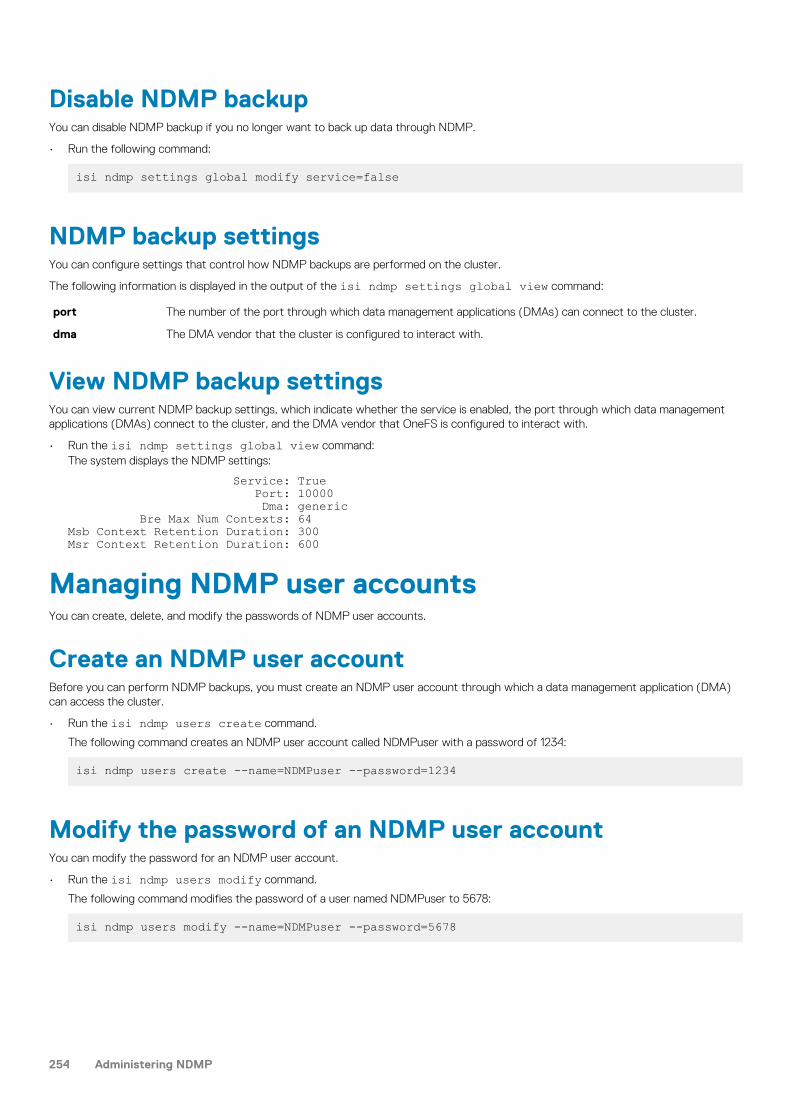
Disable NDMP backupYou can disable NDMP backup if you no longer want to back up data through NDMP.
• Run the following command:
isi ndmp settings global modify service=false
NDMP backup settingsYou can configure settings that control how NDMP backups are performed on the cluster.
The following information is displayed in the output of the isi ndmp settings global view command:
port The number of the port through which data management applications (DMAs) can connect to the cluster.
dma The DMA vendor that the cluster is configured to interact with.
View NDMP backup settingsYou can view current NDMP backup settings, which indicate whether the service is enabled, the port through which data managementapplications (DMAs) connect to the cluster, and the DMA vendor that OneFS is configured to interact with.
• Run the isi ndmp settings global view command:The system displays the NDMP settings:
Service: True Port: 10000 Dma: generic Bre Max Num Contexts: 64Msb Context Retention Duration: 300Msr Context Retention Duration: 600
Managing NDMP user accountsYou can create, delete, and modify the passwords of NDMP user accounts.
Create an NDMP user accountBefore you can perform NDMP backups, you must create an NDMP user account through which a data management application (DMA)can access the cluster.
• Run the isi ndmp users create command.
The following command creates an NDMP user account called NDMPuser with a password of 1234:
isi ndmp users create --name=NDMPuser --password=1234
Modify the password of an NDMP user accountYou can modify the password for an NDMP user account.
• Run the isi ndmp users modify command.
The following command modifies the password of a user named NDMPuser to 5678:
isi ndmp users modify --name=NDMPuser --password=5678
254 Administering NDMP
Delete an NDMP user accountYou can delete an NDMP user account.
• Run the isi ndmp users delete command.
The following command deletes a user named NDMPuser after a confirmation message:
isi ndmp users delete --name=NDMPuser
View NDMP user accountsYou can view information about NDMP user accounts.
• Run the isi ndmp users view command
The following command displays information about the account for a user named NDMPuser:
isi ndmp users view --name=NDMPuser
Managing NDMP backup devicesAfter you attach a tape or media changer device to a Fibre Attached Storage node, you must configure OneFS to detect and establish aconnection to the device. After the connection between the cluster and the backup device is established, you can modify the name thatthe cluster has assigned to the device, or disconnect the device from the cluster.
In case the virtual tape library (VTL) device has multiple LUNs, you must configure LUN0 so that all the LUNs are detected properly.
Detect NDMP backup devicesIf you connect devices to a Backup Accelerator node, you must configure OneFS to detect the devices before OneFS can back up data toand restore data from the devices. You can scan a specific node, a specific port, or all ports on all nodes.
• Run the isi tape rescan command.
The following command detects devices on node 18:
isi tape rescan --node=18
Modify an NDMP backup device entry nameYou can modify the name of an NDMP device entry.
• Run the isi tape modify command.
The following command renames tape003 to tape005:
isi tape modify --name=tape003 --new-name=tape005
Delete a device entry for a disconnected NDMP backupdeviceIf you physically remove an NDMP device from a cluster, OneFS retains the entry for the device. You can delete a device entry for aremoved device. You can also remove the device entry for a device that is still physically attached to the cluster; this causes OneFS todisconnect from the device.
If you remove a device entry for a device that is connected to the cluster, and you do not physically disconnect the device, OneFS willdetect the device the next time it scans the ports. You cannot remove a device entry for a device that is currently being backed up to orrestored from.
Administering NDMP 255

• The following command disconnects tape001 from the cluster:
isi tape delete --name=tape001
View NDMP backup devicesYou can view information about tape and media changer devices that are currently attached to the cluster through a Backup Acceleratornode.
• Run the following command to list tape devices on node 18:
isi tape list --node=18 --tape
Managing NDMP Fibre Channel portsYou can manage the Fibre Channel ports that connect tape and media changer devices to a Fibre Attached Storage node. You can alsoenable, disable, or modify the settings of an NDMP Fibre Channel port.
Modify NDMP backup port settingsYou can modify the settings of an NDMP backup port.
• Run the isi fc settings modify command.
The following command configures port 1 on node 5 to support a point-to-point Fibre Channel topology:
isi fc settings modify --port=5.1 --topology=ptp
Enable or disable an NDMP backup portYou can enable or disable an NDMP backup port.
• Run the isi fc settings modify command:
The following command disables port 1 on node 5:
isi fc settings modify --port=5.1 --state=disable
The following command enables port 1 on node 5:
isi fc settings modify --port=5.1 --state=enable
View NDMP backup portsYou can view information about Fibre Channel ports of Backup Accelerator nodes attached to a cluster.
• Run the following command to view Fibre Channel port settings for port 1 on node 5:
isi fc settings view --port=5.1
NDMP backup port settingsOneFS assigns default settings to each port on each Backup Accelerator node attached to the cluster. These settings identify each portand specify how the port interacts with NDMP backup devices.
The following information is displayed in the output of the isi fc settings list command:
256 Administering NDMP

Port The name of the Backup Accelerator node, and the number of the port.
WWNN The world wide node name (WWNN) of the port. This name is the same for each port on a given node.
WWPN The world wide port name (WWPN) of the port. This name is unique to the port.
State Whether the port is enabled or disabled.
Topology The type of Fibre Channel topology that the port is configured to support.
Rate The rate at which data is sent through the port. The rate can be set to 1 Gb/s, 2 Gb/s, 4 Gb/s, 8 Gb/s, and Auto.8 Gb/s is available for A100 nodes only. If set to Auto, OneFS automatically negotiates with the DMA to determinethe rate. Auto is the recommended setting.
Firmware The firmware version for OCS ports. For Qlogic ports, the firmware version appears blank.
Managing NDMP preferred IP settingsIf you are performing NDMP three-way operations using Avamar in an environment with multiple network interfaces, you can create,modify, delete, list, and view cluster-wide or subnet-specific NDMP preferred IP settings.
You can manage NDMP preferred IP settings only through the OneFS command-line interface.
Create an NDMP preferred IP settingIf you are performing an NDMP three-way backup or restore operation using Avamar, you can create a cluster-wide or a subnet-specificNDMP preferred IP setting.
• Create an NDMP preferred IP setting by running the isi ndmp settings preferred-ips create command.For example, run the following command to apply a preferred IP setting for a cluster:
isi ndmp settings preferred-ips create cluster groupnet0.subnet0,10gnet.subnet0
Run the command as shown in the following example to apply a preferred IP setting for a subnet group:
isi ndmp settings preferred-ips create 10gnet.subnet0 10gnet.subnet0,groupnet0.subnet0
Modify an NDMP preferred IP settingIf you are performing an NDMP three-way backup or restore operation using Avamar, you can modify an NDMP preferred IP setting byadding or deleting a subnet group.
• Modify an NDMP preferred IP setting by running the isi ndmp settings preferred-ips modify command.For example, run the following commands to modify the NDMP preferred IP setting for a cluster:
isi ndmp settings preferred-ips modify 10gnet.subnet0 --add-data-subnets 10gnet.subnet0,groupnet0.subnet0
Run the command as shown in the following example to modify the NDMP preferred IP setting for a subnet:
isi ndmp settings preferred-ips modify 10gnet.subnet0 --remove-data-subnets groupnet0.subnet0
List NDMP preferred IP settingsIf you are performing an NDMP three-way backup or restore operation using Avamar, you can list all the NDMP preferred IP settings.
• List the NDMP preferred IP settings by running the isi ndmp settings preferred-ips list command.For example, run the following command to list the NDMP preferred IP settings:
isi ndmp settings preferred-ips list
Administering NDMP 257

View NDMP preferred IP settingsIf you are performing an NDMP three-way backup or restore operation using Avamar, you can view the NDMP preferred IP settings for asubnet or cluster.
• View an NDMP preferred IP setting by running the isi ndmp settings preferred-ips view command.For example, run the following command to view the NDMP preferred IP setting for a subnet:
isi ndmp settings preferred-ips view --scope=10gnet.subnet0
Delete NDMP preferred IP settingsIf you are performing an NDMP three-way backup or restore operation using Avamar, you can delete an NDMP preferred IP setting for asubnet or cluster.
• Delete NDMP preferred IP settings by running the isi ndmp settings preferred-ips delete command.For example, run the following command to delete the preferred IP setting for a subnet:
isi ndmp settings preferred-ips delete --scope=10gnet.subnet0
Managing NDMP sessionsYou can view the status of NDMP sessions or terminate a session that is in progress.
End an NDMP sessionYou can interrupt an NDMP backup or restore operation by ending an NDMP session.
1. To retrieve the ID of the NDMP session that you want to end, run the isi ndmp sessions list command.
2. Run the isi ndmp sessions delete command.The following command ends an NDMP session with an ID of 4.36339 and skips the confirmation prompt:
isi ndmp sessions delete --session=4.36339 --force
View NDMP sessionsYou can view information about NDMP sessions that exist between the cluster and data management applications (DMAs).
• Run the isi ndmp sessions view command. The following command displays information about session 4.36339.
isi ndmp sessions view --session=4.36339
NDMP session informationYou can view information about active NDMP sessions.
The following information is displayed in the output of the isi ndmp sessions list command:
Session Displays the unique identification number that OneFS assigned to the session.
Data Specifies the current state of the data server.
Mover Specifies the current state of the data mover.
OP Specifies the type of operation (backup or restore) that is currently in progress. If no operation is in progress, thisfield is blank. A backup operation could include the following details:
B({M} {F} [L[0-10] | T0 | Ti | S[0-10]] {r | R})
Where:
258 Administering NDMP

[ a ]—a is required
{ a }—a is optional
a | b—a or b but not at the same time
M—Multi-stream backup
F—File list
L—Level-based
T—Token-based
S—Snapshot mode
s—Snapshot mode and a full backup (when root dir is new)
r—Restartable backup
R—Restarted backup
0-10—Dump level
A restore operation could include the following details:
R ({M|s}[F | D | S]{h})
Where:
M—Multi-stream restore
s—Single-threaded restore (when RESTORE_OPTIONS=1)
F—Full restore
D—DAR
S—Selective restore
h—Restore hardlinks by table
Elapsed Time Specifies the time that has elapsed since the session started.
Bytes Moved Specifies the amount of data in bytes that was transferred during the session.
Throughput Specifies the average throughput of the session over the past five minutes.
NDMP backup and restore operations
Examples of active NDMP backup sessions indicated through the OP setting described previously are as follows:
B(T0): Token based full backup B(Ti): Token based incremental backup B(L0): Level based full backup B(L5): Level 5 incremental backup B(S0): Snapshot based full backup B(S3): Snapshot based level 3 backup B(FT0): Token based full filelist backup B(FL4): Level 4 incremental filelist backup B(L0r): Restartable level based full backup B(S4r): Restartable snapshot based level 4 incremental backup B(L7R): Restarted level 7 backup B(FT1R): Restarted token based incremental filelist backup B(ML0): Multi-stream full backup
Examples of active NDMP restore sessions indicated through the OP setting described previously are as follows:
R(F): Full restoreR(D): DARR(S): Selective restoreR(MF): Multi-stream full restoreR(sFh): single threaded full restore with restore hardlinks by table option
Administering NDMP 259

Managing NDMP restartable backupsAn NDMP restartable backup also known as backup restartable extension (BRE) is a type of backup that you can enable in your datamanagement application (DMA). If a restartable backup fails, for example, because of a power outage, you can restart the backup from acheckpoint close to the point of failure. In contrast, when a non-restartable backup fails, you must back up all data from the beginning,regardless of what was transferred during the initial backup process.
After you enable restartable backups from your DMA, you can manage restartable backup contexts from OneFS. These contexts are thedata that OneFS stores to facilitate restartable backups. Each context represents a checkpoint that the restartable backup process canreturn to if a backup fails. There can be only one restartable backup context per restartable backup session. A backup restartable contextcontains working files in the state of the latest checkpoint.
Restartable backups are supported for NetWorker 8.1 and later versions and CommVault Simpana DMAs.
NOTE: NDMP multi-stream backup does not support restartable backups.
Configure NDMP restartable backups for NetWorkerYou must configure NetWorker to enable NDMP restartable backups and, optionally, define the checkpoint interval.
If you do not specify a checkpoint interval, NetWorker uses the default interval of 5 GB.
1. Configure the client and the directory path that you want to back up as you would normally.2. In the Client Properties dialog box, enable restartable backups.
a. On the General page, click the Checkpoint enabled checkbox.b. In the Checkpoint granularity drop-down list, select File.
3. In the Application information field, type any NDMP variables that you want to specify.The following variable setting specifies a checkpoint interval of 1 GB: CHECKPOINT_INTERVAL_IN_BYTES=1GB
4. Finish configuration and click OK in the Client Properties dialog box.5. Start the backup.6. If the backup is interrupted—for example, because of a power failure—restart it.
a. On the Monitoring page, locate the backup process in the Groups list.b. Right-click the backup process and then, in the context menu, click Restart.
NetWorker automatically restarts the backup from the last checkpoint.
View NDMP restartable backup contextsYou can view NDMP restartable backup contexts that have been configured.
1. List all the restartable backup contexts by running the following command:
isi ndmp contexts list --type=bre
2. To view detailed information about a specific restartable backup context, run the isi ndmp contexts view command.The following command displays detailed information about a backup context with an ID of 792eeb8a-8784-11e2-aa70-0025904e91a4:
isi ndmp contexts view bre_792eeb8a-8784-11e2-aa70-0025904e91a4
Delete an NDMP restartable backup contextAfter an NDMP restartable backup context is no longer needed, your data management application (DMA) automatically requests OneFSto delete the context. You can manually delete a restartable backup context before the DMA requests it.
NOTE: We recommend that you do not manually delete restartable backup contexts. Manually deleting a restartable
backup context requires you to restart the corresponding NDMP backup from the beginning.
• Run the isi ndmp contexts delete command.The following command deletes a restartable backup context with an ID of 792eeb8a-8784-11e2-aa70-0025904e91a4:
isi ndmp contexts delete --id=bre_792eeb8a-8784-11e2-aa70-0025904e91a4
260 Administering NDMP

Configure NDMP restartable backup settingsYou can specify the number of restartable backup contexts that OneFS can retain at a time, up to a maximum of 1024 contexts. Thedefault number of restartable backup contexts is set to 64.
• Run the isi ndmp settings global modify command.The following command sets the maximum number of restartable backup contexts to 128:
isi ndmp settings global modify --bre_max_num_contexts=128
View NDMP restartable backup settingsYou can view the current limit of restartable backup contexts that OneFS retains at one time.
• Run the following command:
isi ndmp settings global view
NDMP restore operationsNDMP supports the following types of restore operations:
• NDMP parallel restore (multi-threaded process)• NDMP serial restore (single-threaded process)
NDMP parallel restore operationParallel (multi-threaded) restore enables faster full or partial restore operations by writing data to the cluster as fast as the data can beread from the tape. Parallel restore is the default restore mechanism in OneFS.
You can restore multiple files concurrently through the parallel restore mechanism.
NDMP serial restore operationFor troubleshooting or for other purposes, you can run a serial restore operation which uses fewer system resources. The serial restoreoperation runs as a single-threaded process and restores one file at a time to the specified path.
Specify a NDMP serial restore operationYou can use the RESTORE_OPTIONS environment variable to specify a serial (single-threaded) restore operation.
1. In your data management application, configure a restore operation as you normally would.2. Make sure that the RESTORE_OPTIONS environment variable is set to 1 on your data management application.
If the RESTORE_OPTIONS environment variable is not already set to 1, specify the isi ndmp settings variables modifycommand from the OneFS command line. The following command specifies serial restore for the /ifs/data/projects directory:
isi ndmp settings variables modify /ifs/data/projects RESTORE_OPTIONS 1
The value of the path option must match the FILESYSTEM environment variable that is set during the backup operation. The valuethat you specify for the name option is case sensitive.
3. Start the restore operation.
Managing default NDMP variablesIn OneFS, you can manage NDMP backup and restore operations by specifying default NDMP environment variables. You can specifyNDMP environment variables for all the backup and restore operations or for a specific path. When you set the path to "/BACKUP", theenvironment variables are applied to all the backup operations. Similarly, when you set the path to "/RESTORE", the environmentvariables are applied to all the restore operations.
Administering NDMP 261

You can override default NDMP environment variables through your data management application (DMA). For more information aboutspecifying NDMP environment variables through your DMA, see the relevant DMA documentation.
Specify the default NDMP variable settings for a pathYou can specify default NDMP variable settings for a path.
1. Open a secure shell (SSH) connection to any node in the Isilon cluster and log in.2. Set default NDMP variables by running the isi ndmp settings variables create command.
For example, the following command enables snapshot-based incremental backups for /ifs/data/media:
isi ndmp settings variables create /ifs/data/media BACKUP_MODE SNAPSHOT
Modify the default NDMP variable settings for a pathYou can modify the default NDMP variable settings for a path.
1. Open a secure shell (SSH) connection to any node in the Isilon cluster and log in.2. Modify default NDMP variable settings by running the isi ndmp settings variables modify command.
For example, the following command sets the default file history format to path-based format for /ifs/data/media:
isi ndmp settings variables modify /ifs/data/media HIST F3. Optional: To remove a default NDMP variable setting for a path, run the isi ndmp settings variables delete command:
For example, the following command removes the default file history format for /ifs/data/media:
isi ndmp settings variables delete /ifs/data/media --name=HIST
NOTE: If you do not specify the --name option, all the variables for the specified path are deleted after a
confirmation.
View the default NDMP settings for a pathYou can view the default NDMP settings for a path.
1. Open a secure shell (SSH) connection to any node in the Isilon cluster and log in.2. View the default NDMP settings by running the following command:
isi ndmp settings variables list
NDMP environment variablesYou can specify default settings of NDMP backup and recovery operations through NDMP environment variables. You can also specifyNDMP environment variables through your data management application (DMA).
Symantec NetBackup and NetWorker are the only two DMAs that allow you to directly set environment variables and propagate them toOneFS.
Table 11. NDMP environment variables
Environment variable Valid values Default Description
BACKUP_FILE_LIST <file-path> None Triggers a file list backup.
Currently, only Networker and SymantecNetBackup can pass environmentvariables to OneFS.
BACKUP_MODE TIMESTAMP TIMESTAMP Enables or disables snapshot-basedincremental backups. To enable
262 Administering NDMP

Table 11. NDMP environment variables(continued)
Environment variable Valid values Default Description
SNAPSHOT snapshot-based incremental backups,specify SNAPSHOT.
BACKUP_OPTIONS 0x000004000x000002000x000001000x000000010x000000020x00000004
0 This environment variable controls thebehavior of the backup operations.
The following settings are applicable onlyto datasets containing the CloudPools-driven SmartLink files:
0x00000400 Backs upSmartLink fileswith full data.This is thecombo copybackup option.
0x00000200 Backs up all thecache data. Thisis the shallowcopy backupoption.
0x00000100 Reads SmartLinkfile data fromthe cloud andbacks up theSmartLink filesas regular files.This is the deepcopy option.
0x00000001 Always addsDUMP_DATEinto the list ofenvironmentvariables at theend of a backupoperation. TheDUMP_DATEvalue is the timewhen thebackup snapshotwas taken. ADMA can usetheDUMP_DATEvalue to setBASE_DATE forthe next backupoperation.
0x00000002 Retains thebackup snapshotof a token-basedbackup in thedumpdates file.Since a token-based backuphas no LEVEL,its level is set to10 by default.
Administering NDMP 263

Table 11. NDMP environment variables(continued)
Environment variable Valid values Default Description
The snapshotallows a faster-incrementalbackup as thenext incrementalbackup after thetoken-basedbackup is done.
0x00000004 Retains the previoussnapshot. After a faster-incremental backup, theprior snapshot is saved atlevel 10. In order to avoidtwo snapshots at the samelevel, the prior snapshot iskept at a lower level in thedumpdates file. This allowsthe BASE_DATE andBACKUP_MODE=snapshotsettings to trigger a faster-incremental backup insteadof a token-based backup.The environment variablesettings prompt the NDMPserver to compare theBASE_DATE value againstthe timestamp in thedumpdates file to find theprior backup. Even thoughthe DMA fails the latestfaster-incremental backup,OneFS retains the priorsnapshot. The DMA canthen retry the faster-incremental backup in thenext backup cycle using theBASE_DATE value of theprior backup.
BASE_DATE Enables a token-based incrementalbackup. The dumpdates file will not beupdated in this case.
DIRECT YN
N Enables or disables Direct AccessRestore (DAR) and Directory DAR(DDAR). The following values are valid:
Y Enables DAR andDDAR.
N Disables DARand DDAR.
EXCLUDE <file-matching-pattern> None If you specify this option, OneFS doesnot back up files and directories thatmeet the specified pattern. Separatemultiple patterns with a space.
FILES <file-matching-pattern> None If you specify this option, OneFS backsup only files and directories that meet
264 Administering NDMP

Table 11. NDMP environment variables(continued)
Environment variable Valid values Default Description
the specified pattern. Separate multiplepatterns with a space.
NOTE: As a rule, files arematched first and then theEXCLUDE pattern is applied.
HIST <file-history-format> Y Specifies the file history format.
The following values are valid:
D Specifiesdirectory ornode file history.
F Specifies path-based filehistory.
Y Specifies thedefault filehistory formatdetermined byyour NDMPbackup settings.
N Disables filehistory.
LEVEL <integer> 0 Specifies the level of NDMP backup toperform. The following values are valid:
0 Performs a fullNDMP backup.
1 - 9 Performs anincrementalbackup at thespecified level.
10 PerformsIncrementalForeverbackups.
MSB_RETENTION_PERIOD Integer 300 sec For a multi-stream backup session,specifies the backup context retentionperiod.
MSR_RETENTION_PERIOD 0 through 60*60*24 600 sec For a multi-stream restore session,specifies the recovery context retentionperiod within which a recovery sessioncan be retried.
RECURSIVE YN
Y For restore sessions only. Specifies thatthe restore session should recover filesor sub-directories under a directoryautomatically.
RESTORE_BIRTHTIME YN
N Specifies whether to recover the birthtime for a recovery session.
RESTORE_HARDLINK _BY_TABLE YN
N For a single-threaded restore session,determines whether OneFS recovershard links by building a hard-link table
Administering NDMP 265

Table 11. NDMP environment variables(continued)
Environment variable Valid values Default Description
during recovery operations. Specify thisoption if hard links are incorrectly backedup and recovery operations are failing.
If a recovery operation fails because hardlinks were incorrectly backed up, thefollowing message appears in the NDMPbackup logs:
Bad hardlink path for <path>NOTE: This variable is noteffective for a parallel restoreoperation.
RESTORE_OPTIONS 0x000000010x000000020x000000040x000001000x00000200
0 This environment variable controls thebehavior of the restore operations.
0x00000001 Performs asingle-threadedrestoreoperation.
0x00000002 Restoresattributes to theexistingdirectories.
0x00000004 Createsintermediatedirectories withdefaultattributes. Thedefault behavioris to getattributes fromthe first objectunder a givendirectory.
The following settings are applicable onlyto datasets backed up with the combocopy backup option:
0x00000100 Forces deepcopy restorationof the SmartLinkfiles. That is,restores thebacked upSmartLink file asa regular file onthe targetcluster.
0x00000200 Forces shallowcopy restorationof the SmartLinkfiles. That is,restores thebacked upSmartLink file asa SmartLink file
266 Administering NDMP

Table 11. NDMP environment variables(continued)
Environment variable Valid values Default Description
on the targetcluster.
UPDATE YN
Y Determines whether OneFS updates thedumpdates file. The default is toperform a combo copy restore.
Y OneFS updatesthe dumpdatesfile.
N OneFS does notupdate thedumpdates file.
Setting environment variables for backup and restoreoperationsYou can set environment variables to support the backup and restore operations for your NDMP session.
You can set environment variables through a data management application (DMA) or the command-line interface. Alternatively, you canset global environment variables. The precedence to apply their settings for a backup or restore operation follows:
• The environment variables specified through a DMA have the highest precedence.• Path-specific environment variables specified by the isi ndmp settings variables take the next precedence.
• Global environment variable settings of "/BACKUP" or "/RESTORE" take the lowest precedence.
You can set environment variables to support different types of backup operations as described in the following scenarios:
• If the BASE_DATE environment variable is set to any value and if you set the BACKUP_MODE environment variable to SNAPSHOT, theLEVEL environment variable is automatically set to 10 and an Incremental Forever backup is performed.
• If the BASE_DATE environment variable is set to 0, a full backup is performed.
• If the BACKUP_MODE environment variable is set to snapshot and the BASE_DATE environment variable is not set to 0, the entriesin the dumpdates file are read and compared with the BASE_DATE environment variable. If an entry is found and a prior validsnapshot is found, a faster incremental backup is performed.
• If the BACKUP_MODE environment variable is set to snapshot, the BASE_DATE environment variable is not set to 0, and if noentries are found in the dumpdates file and no prior valid snapshots are found, a token-based backup is performed using the value ofthe BASE_DATE environment variable.
• If the BASE_DATE environment variable is set, the BACKUP_OPTIONS environment variable is set to 0x0001 by default.
• If the BACKUP_MODE environment variable is set to snapshot, the BACKUP_OPTIONS environment variable is set to 0x0002 bydefault.
• If the BACKUP_OPTIONS environment variable is set to 0x0004 , the snapshot is saved and maintained by the application used forthe backup process.
• In order to run an Incremental Forever backup with faster incremental backups, you must set the following environment variables:
○ BASE_DATE=<time>
○ BACKUP_MODE=snapshot○ BACKUP_OPTIONS=7
Managing snapshot based incremental backupsAfter you enable snapshot-based incremental backups, you can view and delete the snapshots created for these backups.
Administering NDMP 267

Enable snapshot-based incremental backups for adirectoryYou can configure OneFS to perform snapshot-based incremental backups for a directory by default. You can also override the defaultsetting in your data management application (DMA).
• Run the isi ndmp settings variable create command.
The following command enables snapshot-based incremental backups for /ifs/data/media:
isi ndmp settings variables create /ifs/data/media BACKUP_MODE SNAPSHOT
Delete snapshots for snapshot-based incremental backupsYou can delete snapshots created for snapshot-based incremental backups.
NOTE: It is recommended that you do not delete snapshots created for snapshot-based incremental backups. If all
snapshots are deleted for a path, the next backup performed for the path is a full backup.
1. Click Data Protection > NDMP > Environment Settings.2. In the Dumpdates table, click Delete against the entry that you want to delete.3. In the Confirm Delete dialog box, click Delete.
View snapshots for snapshot-based incremental backupsYou can view snapshots generated for snapshot-based incremental backups.
1. Click Data Protection > NDMP > Environment Settings.2. In the Dumpdates table, view information about the snapshot-based incremental backups.
Managing cluster performance for NDMP sessionsNDMP Redirector distributes NDMP loads automatically over nodes with the Sheba network interface card (NIC). You can enable NDMPRedirector to automatically distribute NDMP two-way sessions to nodes with lesser loads. NDMP Redirector checks the CPU usage,number of NDMP operations already running, and the availability of tape devices for the operation on each node before redirecting theNDMP operation. The load-distribution capability results in improved cluster performance when multiple NDMP operations are initiated.
Enable NDMP Redirector to manage cluster performanceYou must enable NDMP Redirector in order to automatically distribute NDMP two-way sessions to nodes with lesser loads.
Make sure that the cluster is committed before enabling NDMP Redirector.
1. Run the following command through the command line interface to enable NDMP Redirector:
isi ndmp settings global modify --enable-redirector true
2. View the setting change by running the following command:
isi ndmp settings global modify
A sample output of the previous command is shown:
Service: False Port: 10000 DMA: generic Bre Max Num Contexts: 64 Context Retention Duration: 300 Smartlink File Open Timeout: 10 Enable Redirector: True
268 Administering NDMP

Managing CPU usage for NDMP sessionsNDMP Throttler manages the CPU usage during NDMP two-way sessions on 6th Generation nodes. The nodes are then available toadequately support other system activities.
Enable NDMP ThrottlerYou must enable NDMP Throttler in order to manage CPU usage of NDMP sessions on 6th Generation nodes.
1. Run the following command through the command line interface to enable NDMP Throttler:
isi ndmp settings global modify --enable-throttler true
2. View the setting change by running the following command:
isi ndmp settings global modify
A sample output of the previous command is shown:
Service: False Port: 10000 DMA: generic Bre Max Num Contexts: 64 Context Retention Duration: 600 Smartlink File Open Timeout: 10 Enable Throttler: TrueThrottler CPU Threshold: 50
3. If required, change the throttler CPU threshold as shown in the following example:
isi ndmp settings global modify –throttler-cpu-threshold 80
View NDMP backup logsYou can view information about NDMP backup and restore operations through NDMP backup logs.
View the contents of the /var/log/isi_ndmp_d directory by running the following command:
more /var/log/isi_ndmp_d
Administering NDMP 269

File retention with SmartLockThis section contains the following topics:
Topics:
• SmartLock overview• Compliance mode• Enterprise mode• SmartLock directories• Replication and backup with SmartLock• SmartLock license functionality• SmartLock considerations• Delete WORM domain and directories• Set the compliance clock• View the compliance clock• Creating a SmartLock directory• Managing SmartLock directories• Managing files in SmartLock directories
SmartLock overviewWith the SmartLock software module, you can protect files on an Isilon cluster from being modified, overwritten, or deleted. To protectfiles in this manner, you must activate a SmartLock license.
With SmartLock, you can identify a directory in OneFS as a WORM domain. WORM stands for write once, read many. All files within theWORM domain can be committed to a WORM state, meaning that those files cannot be overwritten, modified, or deleted.
After a file is removed from a WORM state, you can delete the file. However, you can never modify a file that has been committed to aWORM state, even after it is removed from a WORM state.
In OneFS, SmartLock can be deployed in one of two modes: compliance mode or enterprise mode.
Compliance modeSmartLock compliance mode enables you to protect your data in compliance with the regulations defined by U.S. Securities and ExchangeCommission rule 17a-4. This regulation, aimed at securities brokers and dealers, specifies that records of all securities transactions must bearchived in a non-rewritable, non-erasable manner.
NOTE: You can configure an Isilon cluster for SmartLock compliance mode only during the initial cluster configuration
process, prior to activating a SmartLock license. A cluster cannot be converted to SmartLock compliance mode after
the cluster is initially configured and put into production.
If you configure a cluster for SmartLock compliance mode, the root user is disabled, and you are not able to log in to that cluster throughthe root user account. Instead, you can log in to the cluster through the compliance administrator account that is configured during initialSmartLock compliance mode configuration.
When you are logged in to a SmartLock compliance mode cluster through the compliance administrator account, you can performadministrative tasks through the sudo command.
Enterprise modeYou can create SmartLock domains and apply WORM status to files by activating a SmartLock license on a cluster in standardconfiguration. This is referred to as SmartLock enterprise mode.
SmartLock enterprise mode does not conform to SEC regulations, but does enable you to create SmartLock directories and applySmartLock controls to protect files so that they cannot be rewritten or erased. In addition, the root user account remains on your system.
22
270 File retention with SmartLock

SmartLock directoriesIn a SmartLock directory, you can commit a file to a WORM state manually or you can configure SmartLock to commit the fileautomatically. Before you can create SmartLock directories, you must activate a SmartLock license on the cluster.
You can create two types of SmartLock directories: enterprise and compliance. However, you can create compliance directories only if theIsilon cluster has been set up in SmartLock compliance mode during initial configuration.
Enterprise directories enable you to protect your data without restricting your cluster to comply with regulations defined by U.S. Securitiesand Exchange Commission rule 17a-4. If you commit a file to a WORM state in an enterprise directory, the file can never be modified andcannot be deleted until the retention period passes.
However, if you own a file and have been assigned the ISI_PRIV_IFS_WORM_DELETE privilege, or you are logged in through the rootuser account, you can delete the file through the privileged delete feature before the retention period passes. The privileged delete featureis not available for compliance directories. Enterprise directories reference the system clock to facilitate time-dependent operations,including file retention.
Compliance directories enable you to protect your data in compliance with the regulations defined by U.S. Securities and ExchangeCommission rule 17a-4. If you commit a file to a WORM state in a compliance directory, the file cannot be modified or deleted before thespecified retention period has expired. You cannot delete committed files, even if you are logged in to the compliance administratoraccount. Compliance directories reference the compliance clock to facilitate time-dependent operations, including file retention.
You must set the compliance clock before you can create compliance directories. You can set the compliance clock only once, after whichyou cannot modify the compliance clock time. You can increase the retention time of WORM committed files on an individual basis, ifdesired, but you cannot decrease the retention time.
The compliance clock is controlled by the compliance clock daemon. Root and compliance administrator users could disable thecompliance clock daemon, which would have the effect of increasing the retention period for all WORM committed files. However, this isnot recommended.
NOTE: Using WORM exclusions, files inside a WORM compliance or enterprise domain can be excluded from having a
WORM state. All the files inside the excluded directory will behave as normal non-Smartlock protected files. For more
information, see Exclude a SmartLock directory on page 275.
Replication and backup with SmartLockOneFS enables both compliance and enterprise SmartLock directories to be replicated or backed up to a target cluster.
If you are replicating SmartLock directories with SyncIQ, we recommend that you configure all nodes on the source and target clusterswith Network Time Protocol (NTP) peer mode to ensure that the node clocks are synchronized. For compliance clusters, we recommendthat you configure all nodes on the source and target clusters with NTP peer mode before you set the compliance clocks. This sets thesource and target clusters to the same time initially and helps to ensure compliance with U.S. Securities and Exchange Commission rule17a-4.
NOTE: If you replicate data to a SmartLock directory, do not configure SmartLock settings for that directory until you
are no longer replicating data to the directory. Configuring an autocommit time period for a SmartLock target directory,
for example, can cause replication jobs to fail. If the target directory commits a file to a WORM state, and the file is
modified on the source cluster, the next replication job will fail because it cannot overwrite the committed file.
If you back up data to an NDMP device, all SmartLock metadata relating to the retention date and commit status is transferred to theNDMP device. If you recover data to a SmartLock directory on the cluster, the metadata persists on the cluster. However, if the directorythat you recover data to is not a SmartLock directory, the metadata is lost. You can recover data to a SmartLock directory only if thedirectory is empty.
For information on the limitations of replicating and failing back SmartLock directories with SyncIQ, see SmartLock replication limitationson page 217.
SmartLock license functionalityYou must activate a SmartLock license on an Isilon cluster before you can create SmartLock directories and commit files to a WORMstate.
If a SmartLock license becomes inactive, you will not be able to create new SmartLock directories on the cluster, modify SmartLockdirectory configuration settings, or delete files committed to a WORM state in enterprise directories before their expiration dates.However, you can still commit files within existing SmartLock directories to a WORM state.
File retention with SmartLock 271

If a SmartLock license becomes inactive on a cluster that is running in SmartLock compliance mode, root access to the cluster is notrestored.
SmartLock considerations• If a file is owned exclusively by the root user, and the file exists on an Isilon cluster that is in SmartLock compliance mode, the file will
be inaccessible, because the root user account is disabled in compliance mode. For example, this can happen if a file is assigned rootownership on a cluster that has not been configured in compliance mode, and then the file is replicated to a cluster in compliancemode. This can also occur if a root-owned file is restored onto a compliance cluster from a backup.
• It is recommended that you create files outside of SmartLock directories and then transfer them into a SmartLock directory after youare finished working with the files. If you are uploading files to a cluster, it is recommended that you upload the files to a non-SmartLock directory, and then later transfer the files to a SmartLock directory. If a file is committed to a WORM state while the file isbeing uploaded, the file will become trapped in an inconsistent state.
• Files can be committed to a WORM state while they are still open. If you specify an autocommit time period for a directory, theautocommit time period is calculated according to the length of time since the file was last modified, not when the file was closed. Ifyou delay writing to an open file for more than the autocommit time period, the file is automatically committed to a WORM state, andyou will not be able to write to the file.
• In a Microsoft Windows environment, if you commit a file to a WORM state, you can no longer modify the hidden or archive attributesof the file. Any attempt to modify the hidden or archive attributes of a WORM committed file generates an error. This can preventthird-party applications from modifying the hidden or archive attributes.
• You cannot rename a SmartLock compliance directory. You can rename a SmartLock enterprise directory only if it is empty.• You can only rename files in SmartLock compliance or enterprise directories if the files are uncommitted.• You cannot move:
○ SmartLock directories within a WORM domain○ SmartLock directories in a WORM domain into a directory in a non-WORM domain.○ directories in a non-WORM domain into a SmartLock directory in a WORM domain.
Delete WORM domain and directoriesYou can set an attribute on a WORM domain using the CLI to enable you to delete the directories and files in the domain, and the domainitself. This is useful in the scenario where you created a WORM domain that is not needed, incorrectly named a SmartLock directory, orcreated a SmartLock directory in the wrong location.
In order to delete SmartLock directories and the corresponding WORM domain, you must set the pending delete flag on the domain usingthe isi worm domain modify <domain> --set-pending-delete CLI command. For more information, see Delete aSmartLock directory on page 275.
NOTE: You cannot set the pending delete flag in the Web UI.
Once a WORM domain is marked pending for delete:
• No new files may be created, renamed, or hard-linked into the domain.• Existing files may not be committed or have their retention dates extended.• SyncIQ will fail to sync to and from the domain.
Compliance WORM domain is markedpending for delete
Compliance WORM domain is not markedpending for delete
Deleting a file allowed? Yes, if file is uncommitted or expired Yes, if file is uncommitted or expired
Deleting a directory allowed? Yes, if it doesn't contain committed andunexpired files
Yes, if it doesn't contain committed andunexpired files
Renaming a file allowed? Yes, if uncommitted Yes, if uncommitted
Renaming a directory allowed? No No
Creating a new file allowed? No Yes
272 File retention with SmartLock

Set the compliance clockBefore you can create SmartLock compliance directories, you must set the compliance clock.
Setting the compliance clock configures the clock to the same time as the cluster system clock. Before you set the compliance clock,ensure that the system clock is set to the correct time. If the compliance clock later becomes unsynchronized with the system clock, thecompliance clock will slowly correct itself to match the system clock. The compliance clock corrects itself at a rate of approximately oneweek per year.
1. Open a secure shell (SSH) connection to any node in the cluster and log in through the compliance administrator account.2. Set the compliance clock by running the following command:
isi worm cdate set
View the compliance clockYou can view the current time of the compliance clock.
1. Open a secure shell (SSH) connection to any node in the cluster and log in through the compliance administrator account.2. View the compliance clock by running the following command:
isi worm cdate view
Creating a SmartLock directoryYou can create a SmartLock directory and configure settings that control how long files are retained in a WORM state and when files areautomatically committed to a WORM state. You cannot move or rename a directory that contains a SmartLock directory.
Retention periodsA retention period is the length of time that a file remains in a WORM state before being released from a WORM state. You can configureSmartLock directory settings that enforce default, maximum, and minimum retention periods for the directory.
If you manually commit a file, you can optionally specify the date that the file is released from a WORM state. You can configure aminimum and a maximum retention period for a SmartLock directory to prevent files from being retained for too long or too short a timeperiod. It is recommended that you specify a minimum retention period for all SmartLock directories.
For example, assume that you have a SmartLock directory with a minimum retention period of two days. At 1:00 PM on Monday, youcommit a file to a WORM state, and specify the file to be released from a WORM state on Tuesday at 3:00 PM. The file will be releasedfrom a WORM state two days later on Wednesday at 1:00 PM, because releasing the file earlier would violate the minimum retentionperiod.
You can also configure a default retention period that is assigned when you commit a file without specifying a date to release the file froma WORM state.
Autocommit time periodsYou can configure an autocommit time period for SmartLock directories. An autocommit time period causes files that have been in aSmartLock directory for a period of time without being modified to be automatically committed to a WORM state.
If you modify the autocommit time period of a SmartLock directory that contains uncommitted files, the new autocommit time period isimmediately applied to the files that existed before the modification. For example, consider a SmartLock directory with an autocommittime period of 2 hours. If you modify a file in the SmartLock directory at 1:00 PM, and you decrease the autocommit time period to 1 hourat 2:15 PM, the file is instantly committed to a WORM state.
If a file is manually committed to a WORM state, the read-write permissions of the file are modified. However, if a file is automaticallycommitted to a WORM state, the read-write permissions of the file are not modified.
File retention with SmartLock 273

Create an enterprise directory for a non-empty directoryYou can make a non-empty directory into a SmartLock enterprise directory. This procedure is available only through the command-lineinterface (CLI).
Before creating a SmartLock directory, be aware of the following conditions and requirements:
• You cannot create a SmartLock directory as a subdirectory of an existing SmartLock directory.• Hard links cannot cross SmartLock directory boundaries.• Creating a SmartLock directory causes a corresponding SmartLock domain to be created for that directory.
Run the isi job jobs start command.
The following command creates a SmartLock enterprise domain for /ifs/data/smartlock:
isi job jobs start DomainMark --root /ifs/data/smartlock --dm-type Worm
Create a SmartLock directoryYou can create a SmartLock directory and commit files in that directory to a WORM state.
Before creating a SmartLock directory, be aware of the following conditions and requirements:
• You cannot create a SmartLock directory as a subdirectory of an existing SmartLock directory.• Hard links cannot cross SmartLock directory boundaries.• Creating a SmartLock directory causes a corresponding SmartLock domain to be created for that directory.
Run the isi worm domains create command.
If you specify the path of an existing directory, the directory must be empty.
The following command creates a compliance directory with a default retention period of four years, a minimum retention period of threeyears, and an maximum retention period of five years:
isi worm domains create /ifs/data/SmartLock/directory1 \ --compliance --default-retention 4Y --min-retention 3Y \ --max-retention 5Y --mkdir
The following command creates an enterprise directory with an autocommit time period of thirty minutes and a minimum retention periodof three months:
isi worm domains create /ifs/data/SmartLock/directory2 \ --autocommit-offset 30m --min-retention 3M --mkdir
Managing SmartLock directoriesYou can modify SmartLock directory settings, including the default, minimum, maximum retention period and the autocommit time period.
A SmartLock enterprise directory can be renamed only if the directory is empty. A SmartLock compliance directory cannot be renamed.
Modify a SmartLock directoryYou can modify the SmartLock configuration settings for a SmartLock directory.
NOTE: You can modify SmartLock directory settings only 32 times per directory. It is recommended that you set
SmartLock configuration settings only once and do not modify the settings after files are added to the SmartLock
directory.
1. Open a secure shell (SSH) connection to any node in the cluster and log in.2. Modify SmartLock configuration settings by running the isi worm modify command.
274 File retention with SmartLock

The following command sets the default retention period to one year:
isi worm domains modify /ifs/data/SmartLock/directory1 \--default-retention 1Y
Exclude a SmartLock directoryYou can exclude a SmartLock enterprise mode or compliance mode directory in a WORM domain to exempt the directory and its fileswithin it from WORM retention policies and protection. In order to do this, you must create a WORM exclusion domain on a directory. Thisprocedure is available only through the command-line interface (CLI).
To create a WORM exclusion domain on a directory, the directory must meet all of the following conditions:
• is a member of a WORM domain.• is not the root directory of a WORM domain.• is not the virtual .snapshot directory.
• is not within the compliance store of a WORM compliance domain.• is not within another WORM exclusion domain (nesting).• is empty.
NOTE: You cannot create WORM domains within WORM exclusion domains.
Run the isi worm domain modify /ifs/data/worm_domain --exclude /ifs/data/worm_domain/dir/<excluded_dir> command.
To remove an existing exclusion domain on a directory, you must remove the directory and all of its constituent files.
Delete a SmartLock directoryYou can delete a SmartLock compliance mode directory and its corresponding compliance mode WORM domain (if needed). In order to dothis, you must set the pending delete flag on the domain. You cannot set the pending delete flag on an enterprise mode WORM domain.This procedure is available only through the CLI.
Before marking a compliance mode WORM domain as pending delete, be aware of the following conditions:
• No new files may be created, renamed, or hard-linked into the domain.• Existing files may not be committed or have their retention dates extended.• SyncIQ will fail to sync to and from the domain.
Run the isi worm domain modify <domain> --set-pending-delete command.
View SmartLock directory settingsYou can view the SmartLock directory settings for SmartLock directories.
1. Open a secure shell (SSH) connection to any node in the Isilon cluster and log in.2. View all SmartLock domains by running the following command:
isi worm domains list
The system displays output similar to the following example:
ID Path Type-----------------------------------------------65536 /ifs/data/SmartLock/directory1 enterprise65537 /ifs/data/SmartLock/directory2 enterprise65538 /ifs/data/SmartLock/directory3 enterprise-----------------------------------------------
3. Optional: To view detailed information about a specific SmartLock directory, run the isi worm domains view command.
The following command displays detailed information about /ifs/data/SmartLock/directory2:
isi worm domains view /ifs/data/SmartLock/directory2
The system displays output similar to the following example:
File retention with SmartLock 275

ID: 65537 Path: /ifs/data/SmartLock/directory2 Type: enterprise LIN: 4295426060Autocommit Offset: 30m Override Date: -Privileged Delete: offDefault Retention: 1Y Min Retention: 3M Max Retention: - Total Modifies: 3/32 Max
SmartLock directory configuration settingsYou can configure SmartLock directory settings that determine when files are committed to and how long files are retained in a WORMstate.
ID The numerical ID of the corresponding SmartLock domain.
Path The path of the directory.
Type The type of SmartLock directory.
LIN The inode number of the directory.
Autocommitoffset
The autocommit time period for the directory. After a file exists in this SmartLock directory without beingmodified for the specified time period, the file is automatically committed to a WORM state.
Times are expressed in the format "<integer> <time>", where <time> is one of the following values:
Y Specifies years
M Specifies months
W Specifies weeks
D Specifies days
H Specifies hours
m Specifies minutes
s Specifies seconds
Override date The override retention date for the directory. Files committed to a WORM state are not released from a WORMstate until after the specified date, regardless of the maximum retention period for the directory or whether a userspecifies an earlier date to release a file from a WORM state.
Privileged delete Indicates whether files committed to a WORM state in the directory can be deleted through the privileged deletefunctionality. To access the privilege delete functionality, you must either be assigned theISI_PRIV_IFS_WORM_DELETE privilege and own the file you are deleting. You can also access the privilegedelete functionality for any file if you are logged in through the root or compadmin user account.
on Files committed to a WORM state can be deleted through the isi worm filesdelete command.
off Files committed to a WORM state cannot be deleted, even through the isi wormfiles delete command.
disabled Files committed to a WORM state cannot be deleted, even through the isi wormfiles delete command. After this setting is applied, it cannot be modified.
Default retentionperiod
The default retention period for the directory. If a user does not specify a date to release a file from a WORMstate, the default retention period is assigned.
Times are expressed in the format "<integer> <time>", where <time> is one of the following values:
Y Specifies years
M Specifies months
W Specifies weeks
276 File retention with SmartLock

D Specifies days
H Specifies hours
m Specifies minutes
s Specifies seconds
Forever indicates that WORM committed files are retained permanently by default. Use Min indicates that thedefault retention period is equal to the minimum retention date. Use Max indicates that the default retentionperiod is equal to the maximum retention date.
Minimumretention period
The minimum retention period for the directory. Files are retained in a WORM state for at least the specifiedamount of time, even if a user specifies an expiration date that results in a shorter retention period.
Times are expressed in the format "<integer> <time>", where <time> is one of the following values:
Y Specifies years
M Specifies months
W Specifies weeks
D Specifies days
H Specifies hours
m Specifies minutes
s Specifies seconds
Forever indicates that all WORM committed files are retained permanently.
Maximumretention period
The maximum retention period for the directory. Files cannot be retained in a WORM state for more than thespecified amount of time, even if a user specifies an expiration date that results in a longer retention period.
Times are expressed in the format "<integer> <time>", where <time> is one of the following values:
Y Specifies years
M Specifies months
W Specifies weeks
D Specifies days
H Specifies hours
m Specifies minutes
s Specifies seconds
Forever indicates that there is no maximum retention period.
Managing files in SmartLock directoriesYou can commit files in SmartLock directories to a WORM state by removing the read-write privileges of the file. You can also set aspecific date at which the retention period of the file expires. Once a file is committed to a WORM state, you can increase the retentionperiod of the file, but you cannot decrease the retention period of the file. You cannot move a file that has been committed to a WORMstate, even after the retention period for the file has expired.
The retention period expiration date is set by modifying the access time of a file. In a UNIX command line, the access time can be modifiedthrough the touch command. Although there is no method of modifying the access time through Windows Explorer, you can modify theaccess time through Windows Powershell. Accessing a file does not set the retention period expiration date.
If you run the touch command on a file in a SmartLock directory without specifying a date on which to release the file from a SmartLockstate, and you commit the file, the retention period is automatically set to the default retention period specified for the SmartLockdirectory. If you have not specified a default retention period for the SmartLock directory, the file is assigned a retention period of zeroseconds. It is recommended that you specify a minimum retention period for all SmartLock directories.
File retention with SmartLock 277

Set a retention period through a UNIX command lineYou can specify when a file will be released from a WORM state through a UNIX command line.
1. Open a connection to any node in the Isilon cluster through a UNIX command line and log in.2. Set the retention period by modifying the access time of the file through the touch command.
The following command sets an expiration date of June 1, 2015 for /ifs/data/test.txt:
touch -at 201506010000 /ifs/data/test.txt
Set a retention period through Windows PowershellYou can specify when a file will be released from a WORM state through Microsoft Windows Powershell.
1. Open the Windows PowerShell command prompt.2. Optional: Establish a connection to the Isilon cluster by running the net use command.
The following command establishes a connection to the /ifs directory on cluster.ip.address.com:
net use "\\cluster.ip.address.com\ifs" /user:root password3. Specify the name of the file you want to set a retention period for by creating an object.
The file must exist in a SmartLock directory.
The following command creates an object for /smartlock/file.txt:
$file = Get-Item "\\cluster.ip.address.com\ifs\smartlock\file.txt" 4. Specify the retention period by setting the last access time for the file.
The following command sets an expiration date of July 1, 2015 at 1:00 PM:
$file.LastAccessTime = Get-Date "2015/7/1 1:00 pm"
Commit a file to a WORM state through a UNIX commandlineYou can commit a file to a WORM state through a UNIX command line.
To commit a file to a WORM state, you must remove all write privileges from the file. If a file is already set to a read-only state, you mustfirst add write privileges to the file, and then return the file to a read-only state.
1. Open a connection to the Isilon cluster through a UNIX command line interface and log in.2. Remove write privileges from a file by running the chmod command.
The following command removes write privileges of /ifs/data/smartlock/file.txt:
chmod ugo-w /ifs/data/smartlock/file.txt
Commit a file to a WORM state through Windows ExplorerYou can commit a file to a WORM state through Microsoft Windows Explorer. This procedure describes how to commit a file throughWindows 7.
To commit a file to a WORM state, you must apply the read-only setting. If a file is already set to a read-only state, you must first removethe file from a read-only state and then return it to a read-only state.
1. In Windows Explorer, navigate to the file you want to commit to a WORM state.2. Right-click the folder and then click Properties.3. In the Properties window, click the General tab.4. Select the Read-only check box, and then click OK.
278 File retention with SmartLock

Override the retention period for all files in a SmartLockdirectoryYou can override the retention period for files in a SmartLock directory. All files committed to a WORM state within the directory willremain in a WORM state until after the specified day.
If files are committed to a WORM state after the retention period is overridden, the override date functions as a minimum retention date.All files committed to a WORM state do not expire until at least the given day, regardless of user specifications.
1. Open a secure shell (SSH) connection to any node in the Isilon cluster and log in.2. Override the retention period expiration date for all WORM committed files in a SmartLock directory by running the isi worm
modify command.For example, the following command overrides the retention period expiration date of /ifs/data/SmartLock/directory1 toJune 1, 2014:
isi worm domains modify /ifs/data/SmartLock/directory1 \--override-date 2014-06-01
Delete a file committed to a WORM stateYou can delete a WORM committed file in an enterprise WORM domain before the expiration date through the privileged deletefunctionality. This procedure is available only through the CLI.
• Privileged delete functionality must not be permanently disabled for the SmartLock directory that contains the file.• You must either be the owner of the file and have the ISI_PRIV_IFS_WORM_DELETE and ISI_PRIV_NS_IFS_ACCESS privileges, or
be logged in through the root user account.
1. Open a connection to the Isilon cluster through a UNIX command line and log in.2. If privileged delete functionality was disabled for the SmartLock directory, modify the directory by running the isi worm domains
modify command with the --privileged-delete option.
The following command enables privileged delete for /ifs/data/SmartLock/directory1:
isi worm domains modify /ifs/data/SmartLock/directory1 \--privileged-delete true
3. Delete the WORM committed file by running the isi worm files delete command.
The following command deletes /ifs/data/SmartLock/directory1/file:
isi worm files delete /ifs/data/SmartLock/directory1/file
The system displays output similar to the following:
Are you sure? (yes, [no]):4. Type yes and then press ENTER.
View WORM status of a fileYou can view the WORM status of an individual file. This procedure is available only through the command-line interface (CLI).
1. Open a connection to the Isilon cluster through a UNIX command line.2. View the WORM status of a file by running the isi worm files view command.
For example, the following command displays the WORM status of a file:
isi worm files view /ifs/data/SmartLock/directory1/file
The system displays output similar to the following:
WORM DomainsID Root Path------------------------------------65539 /ifs/data/SmartLock/directory1
File retention with SmartLock 279

WORM State: COMMITTED Expires: 2015-06-01T00:00:00
280 File retention with SmartLock

Data Removal with Instant Secure Erase (ISE)
Instant Secure EraseYou can use the Instant Secure Erase (ISE) functionality to remove confidential data out of a drive before returning the equipment.
OneFS now enables you to use the Instant Secure Erase (ISE) feature. This is a Data Security Standard (DSS) feature that is coupled withisi_drive_d. ISE adds the ability to use the cryptographic sanitize command (SANITIZE-cryptographic for SAS, and CRYPTOSCRAMBLE EXT for ATA). This command helps you to jumble-up readable data on supported drives and securely erase confidential dataout of a drive .
The following drives now have ISE support:
• SAS HDD and SSD:
○ Seagate Skybolt (300GB/600GB/900GB/1.2TB) - 2.5" HDD○ Toshiba PM5 - 2.5" SSD
▪ 3WPD: 400GB/800GB/1.6TB/3.2TB▪ 1WPD: 3.84TB/7.68TB.15.36TB
○ Samsung PM1645 (RFX) - 2.5" SSD
▪ 3WPD: 400GB/800GB/1.6TB/3.2TB▪ 1WPD: 3.84TB/7.68TB.15.36TB
○ Bear Cove Plus - 2.5" SSD
▪ 3WPD: 200GB/400GB/800GB/1.6TB/3.2TB▪ 1WPD: 3.84TB/7.68TB/15.36TB
• SATA HDD:
○ HGST Vela:
▪ Vela-A: 2TB/4TB/6TB▪ Vela-AP: 8TB
○ HGST Leo-A (12TB)
ISE during drive smartfailISE acts automatically during drive smartfail.
After ISE is enabled, the data on the supported drive is erased upon smartfail.
The results are logged into isi_drive_d or isi_drive_history files. Some logs also go to /var/log/messages.
ISE failures and errors do not block the normal smartfail process.
Enable Instant Secure Erase (ISE)Enable ISE from the OneFS command line.
You can configure ISE with drive subsystem configuration.
You must have the ISI_PRIV_DEVICES privilege to enable ISE.
This procedure is available only through the OneFS command-line interface (CLI).
To enable ISE on a drive, enter the following command: isi devices drive config modify --instant-secure-eraseyesISE support is enabled on the cluster.
23
Data Removal with Instant Secure Erase (ISE) 281

View current ISE configurationYou can view the ISE configuration details from the OneFS command line.
You must have the ISI_PRIV_DEVICES privilege view ISE configuration details.
This procedure is available only through the OneFS command-line interface (CLI).
To view the current ISE settings on a drive, enter the following command: isi device drive config viewAn example similar to the following appears.
isi device drive config viewLnn: 1 Instant Secure Erase: Enabled : True
Stall: Max Total Stall Time : 10800 Max Slow Frequency : 0 Max Error Frequency : 0 Diskscrub Stripes : 128 Clear Time : 2592000 Scan Size : 16777216 Scan Max Ecc Delay : 60 Sleep : 30 Max Slow Access : 0
Log: Drive Stats : True
Reboot: None Present : True Chassis Loss : True
Automatic Replacement Recognition: Enabled : True
Allow: Format Unknown Firmware : True Format Unknown Model : True
Spin Wait: Stagger : 5 Check Drive : 45
Alert: Unknown Model : True Unknown Firmware : True
Disable Instant Secure Erase (ISE)Disable ISE from the OneFS command line.
You must have the ISI_PRIV_DEVICES privilege to disable ISE.
This procedure is available only through the OneFS command-line interface (CLI).
To disable ISE support on the drive, enter the following command: isi devices drive config modify --instant-secure-erase noISE support is disabled on the cluster.
282 Data Removal with Instant Secure Erase (ISE)

Protection domainsThis section contains the following topics:
Topics:
• Protection domains overview• Protection domain considerations• Create a protection domain• Delete a protection domain
Protection domains overviewProtection domains are markers that prevent modifications to files and directories. If a domain is applied to a directory, the domain is alsoapplied to all of the files and subdirectories under the directory. You can specify domains manually; however, OneFS usually createsdomains automatically.
There are three types of domains: SyncIQ domains, SmartLock domains, and SnapRevert domains. SyncIQ domains can be assigned tosource and target directories of replication policies. OneFS automatically creates a SyncIQ domain for the target directory of a replicationpolicy the first time that the policy is run. OneFS also automatically creates a SyncIQ domain for the source directory of a replication policyduring the failback process. You can manually create a SyncIQ domain for a source directory before you initiate the failback process byconfiguring the policy for accelerated failback, but you cannot delete a SyncIQ domain that marks the target directory of a replicationpolicy.
SmartLock domains are assigned to SmartLock directories to prevent committed files from being modified or deleted. OneFSautomatically creates a SmartLock domain when a SmartLock directory is created. You cannot delete a SmartLock domain. However, ifyou delete a SmartLock directory, OneFS automatically deletes the SmartLock domain associated with the directory.
SnapRevert domains are assigned to directories that are contained in snapshots to prevent files and directories from being modified whilea snapshot is being reverted. OneFS does not automatically create SnapRevert domains. You cannot revert a snapshot until you create aSnapRevert domain for the directory that the snapshot contains. You can create SnapRevert domains for subdirectories of directoriesthat already have SnapRevert domains. For example, you could create SnapRevert domains for both /ifs/data and /ifs/data/archive. You can delete a SnapRevert domain if you no longer want to revert snapshots of a directory.
Protection domain considerationsYou can manually create protection domains before they are required by OneFS to perform certain actions. However, manually creatingprotection domains can limit your ability to interact with the data marked by the domain.
• Copying a large number of files into a protection domain might take a very long time because each file must be marked individually asbelonging to the protection domain.
• You cannot move directories in or out of protection domains. However, you can move a directory contained in a protection domain toanother location within the same protection domain.
• Creating a protection domain for a directory that contains a large number of files will take more time than creating a protection domainfor a directory with fewer files. Because of this, it is recommended that you create protection domains for directories while thedirectories are empty, and then add files to the directory.
• If a domain is currently preventing the modification or deletion of a file, you cannot create a protection domain for a directory thatcontains that file. For example, if /ifs/data/smartlock/file.txt is set to a WORM state by a SmartLock domain, you cannotcreate a SnapRevert domain for /ifs/data/.
NOTE: If you use SyncIQ to create a replication policy for a SmartLock compliance directory, the SyncIQ and SmartLock
compliance domains must be configured at the same root directory level. A SmartLock compliance domain cannot be
nested inside a SyncIQ domain.
24
Protection domains 283

Create a protection domainYou can create replication or snapshot revert domains to facilitate snapshot revert and failover operations. You cannot create a SmartLockdomain. OneFS automatically creates a SmartLock domain when you create a SmartLock directory.
Run the isi job jobs start command.The following command creates a SyncIQ domain for /ifs/data/source:
isi job jobs start domainmark --root /ifs/data/media \--dm-type SyncIQ
Delete a protection domainYou can delete a replication or snapshot revert domain if you want to move directories out of the domain. You cannot delete a SmartLockdomain. OneFS automatically deletes a SmartLock domain when you delete a SmartLock directory.
Run the isi job jobs start command.
The following command deletes a SyncIQ domain for /ifs/data/source:
isi job jobs start domainmark --root /ifs/data/media \--dm-type SyncIQ --delete
284 Protection domains

Data-at-rest-encryptionThis section contains the following topics:
Topics:
• Data-at-rest encryption overview• Self-encrypting drives• Data security on self-encrypting drives• Data migration to a cluster with self-encrypting drives• Chassis and drive states• Smartfailed drive REPLACE state• Smartfailed drive ERASE state
Data-at-rest encryption overviewYou can enhance data security on a cluster that contains only self-encrypting-drive nodes, providing data-at-rest protection.
The OneFS system is available as a cluster that is composed of OneFS nodes that contain only self-encrypting drives (SEDs). The systemrequirements and management of data at rest on self-encrypting nodes are identical to that of nodes that do not contain self-encryptingdrives. Clusters of mixed node types are not supported.
Self-encrypting drivesSelf-encrypting drives store data on a cluster that is specially designed for data-at-rest encryption.
Data-at-rest encryption on self-encrypting drives occurs when data that is stored on a device is encrypted to prevent unauthorized dataaccess. All data that is written to the storage device is encrypted when it is stored, and all data that is read from the storage device isdecrypted when it is read. The stored data is encrypted with a 256-bit data AES encryption key and decrypted in the same manner.OneFS controls data access by combining the drive authentication key with on-disk data-encryption keys.
NOTE: All nodes in a cluster must be of the self-encrypting drive type. Mixed nodes are not supported.
Data security on self-encrypting drivesSmartfailing self-encrypting drives guarantees data security after removal.
Data on self-encrypting drives is protected from unauthorized access by authenticating encryption keys. Encryption keys never leave thedrive. When a drive is locked, successful authentication unlocks the drive for data access.
The data on self-encrypting drives is rendered inaccessible in the following conditions:
• When a self-encrypting drive is smartfailed, drive authentication keys are deleted from the node. The data on the drive cannot bedecrypted and is therefore unreadable, which secures the drive.
• When a drive is smartfailed and removed from a node, the encryption key on the drive is deleted. Because the encryption key forreading data from the drive must be the same key that was used when the data was written, it is impossible to decrypt data that waspreviously written to the drive. When you smartfail and then remove a drive, it is cryptographically erased.
NOTE: Smartfailing a drive is the preferred method for removing a self-encrypting drive. Removing a node that has
been smartfailed guarantees that data is inaccessible.
• When a self-encrypting drive loses power, the drive locks to prevent unauthorized access. When power is restored, data is againaccessible when the appropriate drive authentication key is provided.
25
Data-at-rest-encryption 285

Data migration to a cluster with self-encryptingdrivesYou can have data from your existing cluster migrated to a cluster of nodes made up of self-encrypting drives (SEDs). As a result, allmigrated and future data on the new cluster will be encrypted.
NOTE: Data migration to a cluster with SEDs must be performed by Isilon Professional Services. For more information,
contact your Dell EMC representative.
Chassis and drive statesYou can view chassis and drive state details.
In a cluster, the combination of nodes in different degraded states determines whether read requests, write requests, or both work. Acluster can lose write quorum but keep read quorum. OneFS provides details about the status of chassis and drives in your cluster. Thefollowing table describes all the possible states that you may encounter in your cluster.
State Description Interface Error state
HEALTHY All drives in the node are functioning correctly. Command-line interface,web administrationinterface
L3 A solid state drive (SSD) was deployed as level 3(L3) cache to increase the size of cache memory andimprove throughput speeds.
Command-line interface
SMARTFAIL orSmartfail orrestripe inprogress
The drive is in the process of being removed safelyfrom the file system, either because of an I/O erroror by user request. Nodes or drives in a smartfail orread-only state affect only write quorum.
Command-line interface,web administrationinterface
NOT AVAILABLE A drive is unavailable for a variety of reasons. Youcan click the bay to view detailed information aboutthis condition.
NOTE: In the web administration interface,this state includes the ERASE and
SED_ERROR command-line interface states.
Command-line interface,web administrationinterface
X
SUSPENDED This state indicates that drive activity is temporarilysuspended and the drive is not in use. The state ismanually initiated and does not occur during normalcluster activity.
Command-line interface,web administrationinterface
NOT IN USE A node in an offline state affects both read and writequorum.
Command-line interface,web administrationinterface
REPLACE The drive was smartfailed successfully and is readyto be replaced.
Command-line interfaceonly
STALLED The drive is stalled and undergoing stall evaluation.Stall evaluation is the process of checking drives thatare slow or having other issues. Depending on theoutcome of the evaluation, the drive may return toservice or be smartfailed. This is a transient state.
Command-line interfaceonly
NEW The drive is new and blank. This is the state that adrive is in when you run the isi dev commandwith the -a add option.
Command-line interfaceonly
USED The drive was added and contained an Isilon GUIDbut the drive is not from this node. This drive likelywill be formatted into the cluster.
Command-line interfaceonly
286 Data-at-rest-encryption

State Description Interface Error state
PREPARING The drive is undergoing a format operation. The drivestate changes to HEALTHY when the format issuccessful.
Command-line interfaceonly
EMPTY No drive is in this bay. Command-line interfaceonly
WRONG_TYPE The drive type is wrong for this node. For example, anon-SED drive in a SED node, SAS instead of theexpected SATA drive type.
Command-line interfaceonly
BOOT_DRIVE Unique to the A100 drive, which has boot drives in itsbays.
Command-line interfaceonly
SED_ERROR The drive cannot be acknowledged by the OneFSsystem.
NOTE: In the web administration interface,this state is included in Not available.
Command-line interface,web administrationinterface
X
ERASE The drive is ready for removal but needs yourattention because the data has not been erased. Youcan erase the drive manually to guarantee that datais removed.
NOTE: In the web administration interface,this state is included in Not available.
Command-line interfaceonly
INSECURE Data on the self-encrypted drive is accessible byunauthorized personnel. Self-encrypting drivesshould never be used for non-encrypted datapurposes.
NOTE: In the web administration interface,this state is labeled Unencrypted SED.
Command-line interfaceonly
X
UNENCRYPTED Data on the self-encrypted drive is accessible byunauthorized personnel. Self-encrypting drivesshould never be used for non-encrypted datapurposes.
NOTE: In the command-line interface, thisstate is labeled INSECURE.
Web administrationinterface only
X
Smartfailed drive REPLACE stateYou can see different drive states during the smartfail process.
If you run the isi dev list command while the drive in bay 1 is being smartfailed, the system displays output similar to the followingexample:
Node 1, [ATTN] Bay 1 Lnum 11 [SMARTFAIL] SN:Z296M8HK 000093172YE04 /dev/da1 Bay 2 Lnum 10 [HEALTHY] SN:Z296M8N5 00009330EYE03 /dev/da2 Bay 3 Lnum 9 [HEALTHY] SN:Z296LBP4 00009330EYE03 /dev/da3 Bay 4 Lnum 8 [HEALTHY] SN:Z296LCJW 00009327BYE03 /dev/da4 Bay 5 Lnum 7 [HEALTHY] SN:Z296M8XB 00009330KYE03 /dev/da5 Bay 6 Lnum 6 [HEALTHY] SN:Z295LXT7 000093172YE03 /dev/da6 Bay 7 Lnum 5 [HEALTHY] SN:Z296M8ZF 00009330KYE03 /dev/da7 Bay 8 Lnum 4 [HEALTHY] SN:Z296M8SD 00009330EYE03 /dev/da8 Bay 9 Lnum 3 [HEALTHY] SN:Z296M8QA 00009330EYE03 /dev/da9 Bay 10 Lnum 2 [HEALTHY] SN:Z296M8Q7 00009330EYE03 /dev/da10 Bay 11 Lnum 1 [HEALTHY] SN:Z296M8SP 00009330EYE04 /dev/da11 Bay 12 Lnum 0 [HEALTHY] SN:Z296M8QZ 00009330JYE03 /dev/da12If you run the isi dev list command after the smartfail completes successfully, the system displays output similar to the followingexample, showing the drive state as REPLACE:
Data-at-rest-encryption 287

Node 1, [ATTN] Bay 1 Lnum 11 [REPLACE] SN:Z296M8HK 000093172YE04 /dev/da1 Bay 2 Lnum 10 [HEALTHY] SN:Z296M8N5 00009330EYE03 /dev/da2 Bay 3 Lnum 9 [HEALTHY] SN:Z296LBP4 00009330EYE03 /dev/da3 Bay 4 Lnum 8 [HEALTHY] SN:Z296LCJW 00009327BYE03 /dev/da4 Bay 5 Lnum 7 [HEALTHY] SN:Z296M8XB 00009330KYE03 /dev/da5 Bay 6 Lnum 6 [HEALTHY] SN:Z295LXT7 000093172YE03 /dev/da6 Bay 7 Lnum 5 [HEALTHY] SN:Z296M8ZF 00009330KYE03 /dev/da7 Bay 8 Lnum 4 [HEALTHY] SN:Z296M8SD 00009330EYE03 /dev/da8 Bay 9 Lnum 3 [HEALTHY] SN:Z296M8QA 00009330EYE03 /dev/da9 Bay 10 Lnum 2 [HEALTHY] SN:Z296M8Q7 00009330EYE03 /dev/da10 Bay 11 Lnum 1 [HEALTHY] SN:Z296M8SP 00009330EYE04 /dev/da11 Bay 12 Lnum 0 [HEALTHY] SN:Z296M8QZ 00009330JYE03 /dev/da12If you run the isi dev list command while the drive in bay 3 is being smartfailed, the system displays output similar to the followingexample:
Node 1, [ATTN] Bay 1 Lnum 11 [REPLACE] SN:Z296M8HK 000093172YE04 /dev/da1 Bay 2 Lnum 10 [HEALTHY] SN:Z296M8N5 00009330EYE03 /dev/da2 Bay 3 Lnum 9 [SMARTFAIL] SN:Z296LBP4 00009330EYE03 N/A Bay 4 Lnum 8 [HEALTHY] SN:Z296LCJW 00009327BYE03 /dev/da4 Bay 5 Lnum 7 [HEALTHY] SN:Z296M8XB 00009330KYE03 /dev/da5 Bay 6 Lnum 6 [HEALTHY] SN:Z295LXT7 000093172YE03 /dev/da6 Bay 7 Lnum 5 [HEALTHY] SN:Z296M8ZF 00009330KYE03 /dev/da7 Bay 8 Lnum 4 [HEALTHY] SN:Z296M8SD 00009330EYE03 /dev/da8 Bay 9 Lnum 3 [HEALTHY] SN:Z296M8QA 00009330EYE03 /dev/da9 Bay 10 Lnum 2 [HEALTHY] SN:Z296M8Q7 00009330EYE03 /dev/da10 Bay 11 Lnum 1 [HEALTHY] SN:Z296M8SP 00009330EYE04 /dev/da11 Bay 12 Lnum 0 [HEALTHY] SN:Z296M8QZ 00009330JYE03 /dev/da12
Smartfailed drive ERASE stateAt the end of a smartfail process, OneFS attempts to delete the authentication key on a drive if it is unable to reset the key.
NOTE:
• To securely delete the authentication key on a single drive, smartfail the individual drive.
• To securely delete the authentication key on a single node, smartfail the node.
• To securely delete the authentication keys on an entire cluster, smartfail each node and run the
isi_reformat_node command on the last node.
Upon running the isi dev list command, the system displays output similar to the following example, showing the drive state asERASE:
Node 1, [ATTN] Bay 1 Lnum 11 [REPLACE] SN:Z296M8HK 000093172YE04 /dev/da1 Bay 2 Lnum 10 [HEALTHY] SN:Z296M8N5 00009330EYE03 /dev/da2 Bay 3 Lnum 9 [ERASE] SN:Z296LBP4 00009330EYE03 /dev/da3 Drives showing the ERASE state can be safely retired, reused, or returned.
Any further access to a drive showing the ERASE state requires the authentication key of the drive to be set to its default manufacturedsecurity ID (MSID). This action erases the data encryption key (DEK) on the drive and renders any existing data on the drive permanentlyunreadable.
288 Data-at-rest-encryption

SmartQuotasThis section contains the following topics:
Topics:
• SmartQuotas overview• Quota types• Default quota type• Usage accounting and limits• Disk-usage calculations• Quota notifications• Quota notification rules• Quota reports• Creating quotas• Managing quotas
SmartQuotas overviewThe SmartQuotas module is an optional quota-management tool that monitors and enforces administrator-defined storage limits. Usingaccounting and enforcement quota limits, reporting capabilities, and automated notifications, SmartQuotas manages storage use, monitorsdisk storage, and issues alerts when disk-storage limits are exceeded.
Quotas help you manage storage usage according to criteria that you define. Quotas are used for tracking—and sometimes limiting—theamount of storage that a user, group, or directory consumes. Quotas help ensure that a user or department does not infringe on thestorage that is allocated to other users or departments. In some quota implementations, writes beyond the defined space are denied, andin other cases, a simple notification is sent.
NOTE: Do not apply quotas to /ifs/.ifsvar/ or its subdirectories. If you limit the size of the /ifs/.ifsvar/directory through a quota, and the directory reaches its limit, jobs such as File-System Analytics fail. A quota blocks
older job reports from being deleted from the /ifs/.ifsvar/ subdirectories to make room for newer reports.
The SmartQuotas module requires a separate license. For more information about the SmartQuotas module or to activate the module,contact your Dell EMC sales representative.
Quota typesOneFS uses the concept of quota types as the fundamental organizational unit of storage quotas. Storage quotas comprise a set ofresources and an accounting of each resource type for that set. Storage quotas are also called storage domains.
Storage quotas creation requires three identifiers:
• The directory to monitor• Whether snapshots are tracked against the quota limit• The quota type (directory, user, or group)
NOTE: Do not create quotas of any type on the OneFS root (/ifs). A root-level quota may significantly degrade
performance.
You can choose a quota type from the following entities:
Directory A specific directory and its subdirectories.NOTE: You cannot choose a default directory quota type using the Web UI. You can only create a
default directory quota using the CLI. However, you can manage default directory quotas using
the UI (modify the quota settings, link, and unlink subdirectories). All immediate subdirectories in
26
SmartQuotas 289

a default directory quota inherit the parent directory quota settings unless otherwise modified.
Specific directory quotas that you configure take precedence over a default directory.
User Either a specific user or default user (every user). Specific-user quotas that you configure take precedence over adefault user quota.
Group All members of a specific group or all members of a default group (every group). Any specific-group quotas thatyou configure take precedence over a default group quota. Associating a group quota with a default group quotacreates a linked quota.
You can create multiple quota types on the same directory, but they must be of a different type or have a different snapshot option. Youcan specify quota types for any directory in OneFS and nest them within each other to create a hierarchy of complex storage-use policies.
Nested storage quotas can overlap. For example, the following quota settings ensure that the finance directory never exceeds 5 TB, whilelimiting the users in the finance department to 1 TB each:
• Set a 5 TB hard quota on /ifs/data/finance.
• Set 1 TB soft quotas on each user in the finance department.
Default quota typeDefault quotas automatically create other quotas for users, groups, or immediate subdirectories in a specified directory.
A default quota specifies a policy for new entities that match a trigger. The default-user@/ifs/cs becomes specific-user@/ifs/cs for each specific-user that is not otherwise defined.
Default user quota type exampleFor example, you can create a default-user quota on the /ifs/dir-1 directory, where that directory is owned by the root user. Thedefault-user type automatically creates a domain on that directory for root and adds the usage there:
my-OneFS-1# mkdir /ifs/dir-1my-OneFS-1# isi quota quotas create /ifs/dir-1 default-usermy-OneFS-1# isi quota quotas ls --path=/ifs/dir-1 Type AppliesTo Path Snap Hard Soft Adv Used---------------------------------------------------------------default-user DEFAULT /ifs/dir-1 No - - - 0buser root /ifs/dir-1 No - - - 0b---------------------------------------------------------------Total: 2
Now add a file owned by a different user (admin):
my-OneFS-1# touch /ifs/dir-1/somefilemy-OneFS-1# chown admin /ifs/dir-1/somefilemy-OneFS-1# isi quota quotas ls --path=/ifs/dir-1Type AppliesTo Path Snap Hard Soft Adv Used---------------------------------------------------------------default-user DEFAULT /ifs/dir-1 No - - - 0buser root /ifs/dir-1 No - - - 26buser admin /ifs/dir-1 No - - - 0b---------------------------------------------------------------Total: 3
In this example, the default-user type created a specific-user type automatically (user:admin) and added the new usage to it. Default-userdoes not have any usage because it is used only to generate new quotas automatically. Default-user enforcement is copied to a specific-user (user:admin), and the inherited quota is called a linked quota. In this way, each user account gets its own usage accounting.
Defaults can overlap. For example, default-user@/ifs/dir-1 and default-user@/ifs/cs both may be defined. If the default enforcementchanges, OneFS storage quotas propagate the changes to the linked quotas asynchronously. Because the update is asynchronous, thereis some delay before updates are in effect. If a default type, such as every user or every group, is deleted, OneFS deletes all children thatare marked as inherited. As an option, you can delete the default without deleting the children, but it is important to note that this actionbreaks inheritance on all inherited children.
290 SmartQuotas
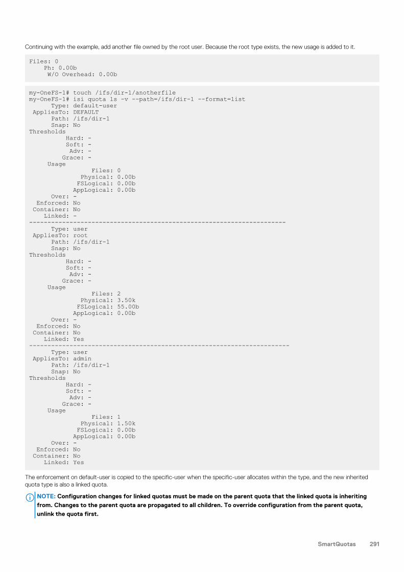
Continuing with the example, add another file owned by the root user. Because the root type exists, the new usage is added to it.
Files: 0 Ph: 0.00b W/O Overhead: 0.00b
my-OneFS-1# touch /ifs/dir-1/anotherfilemy-OneFS-1# isi quota ls -v --path=/ifs/dir-1 --format=list Type: default-user AppliesTo: DEFAULT Path: /ifs/dir-1 Snap: NoThresholds Hard: - Soft: - Adv: - Grace: - Usage Files: 0 Physical: 0.00b FSLogical: 0.00b AppLogical: 0.00b Over: - Enforced: No Container: No Linked: ----------------------------------------------------------------------- Type: user AppliesTo: root Path: /ifs/dir-1 Snap: NoThresholds Hard: - Soft: - Adv: - Grace: - Usage Files: 2 Physical: 3.50k FSLogical: 55.00b AppLogical: 0.00b Over: - Enforced: No Container: No Linked: Yes----------------------------------------------------------------------- Type: user AppliesTo: admin Path: /ifs/dir-1 Snap: NoThresholds Hard: - Soft: - Adv: - Grace: - Usage Files: 1 Physical: 1.50k FSLogical: 0.00b AppLogical: 0.00b Over: - Enforced: No Container: No Linked: Yes
The enforcement on default-user is copied to the specific-user when the specific-user allocates within the type, and the new inheritedquota type is also a linked quota.
NOTE: Configuration changes for linked quotas must be made on the parent quota that the linked quota is inheriting
from. Changes to the parent quota are propagated to all children. To override configuration from the parent quota,
unlink the quota first.
SmartQuotas 291

Default directory quota example typeIf a default directory quota is configured on the /ifs/parent folder, then any immediate subdirectory created within that folderautomatically inherits quota configuration information from the default domain. Only immediate subdirectories inherit default directoryquotas; a subdirectory within an immediate subdirectory (a second-level or deeper subdirectory) will not inherit the default directoryquota. For example, you create a default-directory quota type on the /ifs/parent directory. Then you create the /ifs/parent/child subdirectory. This subdirectory inherits the default directory quota settings. Then you create the second-level /ifs/parent/child/grandchild subdirectory. This subdirectory does not inherit the default directory quota settings.
Usage accounting and limitsStorage quotas can perform two functions: they monitor storage space through usage accounting and they manage storage spacethrough enforcement limits.
You can configure OneFS quotas by usage type to track or limit storage use. The accounting option, which monitors disk-storage use, isuseful for auditing, planning, and billing. Enforcement limits set storage limits for users, groups, or directories.
Track storageconsumptionwithout specifyinga storage limit
The accounting option tracks but does not limit disk-storage use. Using the accounting option for a quota, you canmonitor inode count and physical and logical space resources. Physical space refers to all of the space that is usedto store files and directories, including data, metadata, and data protection overhead in the domain. There are twotypes of logical space:
• File system logical size: Logical size of files as per file system. Sum of all files sizes, excluding file metadata anddata protection overhead.
• Application logical size : Logical size of file apparent to the application. Used file capacity from the applicationpoint of view, which is usually equal to or less than the file system logical size. However, in the case of asparse file, application logical size can be greater than file system logical size. Application logical size includescapacity consumption on the cluster as well as data tiered to the cloud.
Storage consumption is tracked using file system logical size by default, which does not include protectionoverhead. As an example, by using the accounting option, you can do the following:
• Track the amount of disk space that is used by various users or groups to bill each user, group, or directory foronly the disk space used.
• Review and analyze reports that help you identify storage usage patterns and define storage policies.• Plan for capacity and other storage needs.
Specify storagelimits
Enforcement limits include all of the functionality of the accounting option, plus the ability to limit disk storage andsend notifications. Using enforcement limits, you can logically partition a cluster to control or restrict how muchstorage that a user, group, or directory can use. For example, you can set hard- or soft-capacity limits to ensurethat adequate space is always available for key projects and critical applications and to ensure that users of thecluster do not exceed their allotted storage capacity. Optionally, you can deliver real-time email quota notificationsto users, group managers, or administrators when they are approaching or have exceeded a quota limit.
NOTE:
If a quota type uses the accounting-only option, enforcement limits cannot be used for that quota.
The actions of an administrator who is logged in as root may push a domain over a quota threshold. For example, changing the protectionlevel or taking a snapshot has the potential to exceed quota parameters. System actions such as repairs also may push a quota domainover the limit.
The system provides three types of administrator-defined enforcement thresholds.
Threshold type Description
Hard Limits disk usage to a size that cannot be exceeded. If an operation, such as a file write, causes aquota target to exceed a hard quota, the following events occur:
• The operation fails• An alert is logged to the cluster• A notification is issued to specified recipients.
Writes resume when the usage falls below the threshold.
292 SmartQuotas

Threshold type Description
Soft Allows a limit with a grace period that can be exceeded until the grace period expires. When a softquota is exceeded, an alert is logged to the cluster and a notification is issued to specified recipients;however, data writes are permitted during the grace period.
If the soft threshold is still exceeded when the grace period expires, data writes fail, and a notificationis issued to the recipients you have specified.
Writes resume when the usage falls below the threshold.
Advisory An informational limit that can be exceeded. When an advisory quota threshold is exceeded, an alert islogged to the cluster and a notification is issued to specified recipients. Advisory thresholds do notprevent data writes.
Disk-usage calculationsFor each quota that you configure, you can specify whether physical or logical space is included in future disk usage calculations.
You can configure quotas to include the following types of physical or logical space:
Type of physical orlogical space toinclude in quota
Description
Physical size Total on-disk space consumed to store files inOneFS. Apart from file data, this counts usermetadata (for example, ACLs and user-specifiedextended attributes) and data protection overhead.Accounts for on-premise capacity consumption withdata protection.
File data blocks (non-sparse regions) + IFS metadata(ACLs, ExAttr, inode) + data protection overhead
File system logical size Approximation of disk usage on other systems byignoring protection overhead. The space consumedto store files with 1x protection. Accounts for on-premise capacity consumption without dataprotection.
File data blocks (non-sparse regions) + IFS metadata(Acls, ExAttr, inode)
Application logical size Apparent size of file that a user/applicationobserves. How an application sees space available forstorage regardless of whether files are cloud-tiered,sparse, deduped, or compressed. It is the offset ofthe file's last byte (end-of-file). Application logicalsize is unaffected by the physical location of thedata, on or off cluster, and therefore includesCloudPools capacity across multiple locations.Accounts for on-premise and off-premise capacityconsumption without data protection.
The physical size and file system logical size quotametrics count the number of blocks required to storefile data (block-aligned). The application logical sizequota metric is not block-aligned. In general, theapplication logical size is smaller than either thephysical size or file system logical size, as the filesystem logical size counts the full size of the lastblock of the file, whereas application logical sizeconsiders the data present in the last block.However, application logical size will be higher forsparse files.
Most quota configurations do not need to include data protection overhead calculations, and therefore do not need to include physicalspace, but instead can include logical space (either file system logical size, or application logical size). If you do not include data protectionoverhead in usage calculations for a quota, future disk usage calculations for the quota include only the logical space that is required tostore files and directories. Space that is required for the data protection setting of the cluster is not included.
Consider an example user who is restricted by a 40 GB quota that does not include data protection overhead in its disk usage calculations.(The 40 GB quota includes file system logical size or application logical size.) If your cluster is configured with a 2x data protection leveland the user writes a 10 GB file to the cluster, that file consumes 20 GB of space but the 10GB for the data protection overhead is notcounted in the quota calculation. In this example, the user has reached 25 percent of the 40 GB quota by writing a 10 GB file to thecluster. This method of disk usage calculation is recommended for most quota configurations.
If you include data protection overhead in usage calculations for a quota, future disk usage calculations for the quota include the totalamount of space that is required to store files and directories, in addition to any space that is required to accommodate your dataprotection settings, such as parity or mirroring. For example, consider a user who is restricted by a 40 GB quota that includes dataprotection overhead in its disk usage calculations. (The 40 GB quota includes physical size.) If your cluster is configured with a 2x dataprotection level (mirrored) and the user writes a 10 GB file to the cluster, that file actually consumes 20 GB of space: 10 GB for the file and
SmartQuotas 293

10 GB for the data protection overhead. In this example, the user has reached 50 percent of the 40 GB quota by writing a 10 GB file to thecluster.
NOTE: Cloned and deduplicated files are treated as ordinary files by quotas. If the quota includes data protection
overhead, the data protection overhead for shared data is not included in the usage calculation.
You can configure quotas to include the space that is consumed by snapshots. A single path can have two quotas applied to it: onewithout snapshot usage, which is the default, and one with snapshot usage. If you include snapshots in the quota, more files are includedin the calculation than are in the current directory. The actual disk usage is the sum of the current directory and any snapshots of thatdirectory. You can see which snapshots are included in the calculation by examining the .snapshot directory for the quota path.
NOTE: Only snapshots created after the QuotaScan job finishes are included in the calculation.
Quota notificationsQuota notifications are generated for enforcement quotas, providing users with information when a quota violation occurs. Reminders aresent periodically while the condition persists.
Each notification rule defines the condition that is to be enforced and the action that is to be executed when the condition is true. Anenforcement quota can define multiple notification rules. When thresholds are exceeded, automatic email notifications can be sent tospecified users, or you can monitor notifications as system alerts or receive emails for these events.
Notifications can be configured globally, to apply to all quota domains, or be configured for specific quota domains.
Enforcement quotas support the following notification settings. A given quota can use only one of these settings.
Limit notification settings Description
Disable quota notifications Disables all notifications for the quota.
Use the system settings for quota notifications Uses the global default notification for the specified type of quota.
Create custom notifications rules Enables the creation of advanced, custom notifications that applyto the specific quota. Custom notifications can be configured forany or all of the threshold types (hard, soft, or advisory) for thespecified quota.
Quota notification rulesYou can write quota notification rules to generate alerts that are triggered by event thresholds.
When an event occurs, a notification is triggered according to your notification rule. For example, you can create a notification rule thatsends an email when a disk-space allocation threshold is exceeded by a group.
You can configure notification rules to trigger an action according to event thresholds (a notification condition). A rule can specify aschedule, such as "every day at 1:00 AM," for executing an action or immediate notification of certain state transitions. When an eventoccurs, a notification trigger may execute one or more actions, such as sending an email or sending a cluster alert to the interface. Thefollowing examples demonstrate the types of criteria that you can use to configure notification rules.
• Notify when a threshold is exceeded; at most, once every 5 minutes• Notify when allocation is denied; at most, once an hour• Notify while over threshold, daily at 2 AM• Notify while grace period expired weekly, on Sundays at 2 AM
Notifications are triggered for events grouped by the following categories:
Instantnotifications
Includes the write-denied notification, triggered when a hard threshold denies a write, and the threshold-exceedednotification, triggered at the moment a hard, soft, or advisory threshold is exceeded. These are one-timenotifications because they represent a discrete event in time.
Ongoingnotifications
Generated on a scheduled basis to indicate a persisting condition, such as a hard, soft, or advisory threshold beingover a limit or a soft threshold's grace period being expired for a prolonged period.
294 SmartQuotas

Quota reportsThe OneFS SmartQuotas module provides reporting options that enable administrators to manage cluster resources and analyze usagestatistics.
Storage quota reports provide a summarized view of the past or present state of the quota domains. After raw reporting data is collectedby OneFS, you can produce data summaries by using a set of filtering parameters and sort types. Storage-quota reports includeinformation about violators, grouped by threshold types. You can generate reports from a historical data sample or from current data. Ineither case, the reports are views of usage data at a given time. OneFS does not provide reports on data aggregated over time, such astrending reports, but you can use raw data to analyze trends. There is no configuration limit on the number of reports other than thespace needed to store them.
OneFS provides the following data-collection and reporting methods:
• Scheduled reports are generated and saved on a regular interval.• Ad hoc reports are generated and saved at the request of the user.• Live reports are generated for immediate and temporary viewing.
Scheduled reports are placed by default in the /ifs/.isilon/smartquotas/reports directory, but the location is configurable toany directory under /ifs. Each generated report includes quota domain definition, state, usage, and global configuration settings. Bydefault, ten reports are kept at a time, and older reports are purged. You can create ad hoc reports at any time to view the current stateof the storage quotas system. These live reports can be saved manually. Ad hoc reports are saved to a location that is separate fromscheduled reports to avoid skewing the timed-report sets.
Creating quotasYou can create two types of storage quotas to monitor data: accounting quotas and enforcement quotas. Storage quota limits andrestrictions can apply to specific users, groups, or directories.
The type of quota that you create depends on your goal.
• Enforcement quotas monitor and limit disk usage. You can create enforcement quotas that use any combination of hard limits, softlimits, and advisory limits.
NOTE: Enforcement quotas are not recommended for snapshot-tracking quota domains.
• Accounting quotas monitor, but do not limit, disk usage.
NOTE: Before using quota data for analysis or other purposes, verify that no QuotaScan jobs are running.
Create an accounting quotaYou can create an accounting quota to monitor but not limit disk usage.
Optionally, you can include snapshot data, data-protection overhead, or both in the accounting quota.
For information about the parameters and options that you can use for this procedure, run the isi quota quotas create --helpcommand.
Run the isi quota quotas create command to create an accounting quota.The following command creates a quota for the /quota_test_1 directory. The quota sets an advisory threshold that is informativerather than enforced.
isi quota quotas create /ifs/data/quota_test_1 directory \ --advisory-threshold=10M --enforced=false
Before using quota data for analysis or other purposes, verify that no QuotaScan jobs are in progress by running the isi job eventslist --job-type quotascan command.
Create an enforcement quotaYou can create an enforcement quota to monitor and limit disk usage.
You can create enforcement quotas that set hard, soft, and advisory limits.
For information about the parameters and options that you can use for this procedure, run the isi quota quotas create --helpcommand.
SmartQuotas 295

Run the isi quota quotas create command and set the --enforced parameter to true.The following command creates a quota for the /quota_test_2 directory. The quota sets an advisory threshold that is enforced whenthe threshold specified is exceeded.
isi quota quotas create /ifs/data/quota_test_2 directory \ --advisory-threshold=100M --enforced=true
Before using quota data for analysis or other purposes, verify that no QuotaScan jobs are in progress by running the isi job eventslist --job-type quotascan command.
Managing quotasYou can modify the configured values of a storage quota, and you can enable or disable a quota. You can also create quota limits andrestrictions that apply to specific users, groups, or directories.
Quota management in OneFS is simplified by the quota search feature, which helps you locate a quota or quotas by using filters. You canunlink quotas that are associated with a parent quota, and configure custom notifications for quotas. You can also disable a quotatemporarily and then enable it when needed.
NOTE: Moving quota directories across quota domains is not supported.
Search for quotasYou can search for a quota using a variety of search parameters.
For information about the parameters and options that you can use for this procedure, run the isi quota quotas list --helpcommand.
Run the isi quota quotas list command to search for quotas.The following command finds all quotas that monitor the /ifs/data/quota_test_1 directory:
isi quota quotas list --path=/ifs/data/quota_test_1
Manage quotasQuotas help you monitor and analyze the current or historic use of disk storage. You can search for quotas, and modify, delete, and unlinkquotas.
You must run an initial QuotaScan job for the default or scheduled quotas to prevent displaying incomplete data.
Before you modify a quota, consider how the changes will affect the file system and end users.
For information about the parameters and options that you can use for this procedure, run the isi quota quotas list --helpcommand.
NOTE:
• You can edit or delete a quota report only when the quota is not linked to a default quota.
• You can unlink a quota only when the quota is linked to a default quota.
1. To monitor and analyze current disk storage, run the isi quota quotas view command.The following example provides current usage information for the root user on the specified directory and includes snapshot data. Formore information about the parameters for this command, run the isi quota quotas list --help command.
isi quota quotas list -v --path=/ifs/data/quota_test_2 \ --include-snapshots="yes"
2. To view all information in the quota report, run the isi quota reports list command.To view specific information in a quota report, run the isi quota quotas list --help command to view the filter parameters.The following command lists all information in the quota report:
isi quota reports list -v3. Optional: To delete a quota, run the isi quota quotas delete command.
296 SmartQuotas

The following command deletes the specified directory-type quota. For information about parameters for this command, run the isiquota quotas delete --help command:
isi quota quotas delete /ifs/data/quota_test_2 directory4. To unlink a quota, run the isi quota quotas modify command.
The following command example unlinks a user quota:
isi quota quotas modify /ifs/dir-1 user --linked=false --user=admin
NOTE: Configuration changes for linked quotas must be made on the parent (default) quota that the linked quota is
inheriting from. Changes to the parent quota are propagated to all children. If you want to override configuration
from the parent quota, you must first unlink the quota.
Export a quota configuration fileYou can export quota settings as a configuration file, which can then be imported for reuse to another Isilon cluster. You can also store theexported quota configurations in a location outside of the cluster. This task may only be performed from the OneFS command lineinterface.
You can pipe the XML report to a file or directory. The file can then be imported to another cluster.
1. Open a secure shell (SSH) connection to any node in the cluster and log in.2. At the command prompt, run the following command:
isi_classic quota list --export
The quota configuration file displays as raw XML.
Import a quota configuration fileYou can import quota settings in the form of a configuration file that has been exported from another Isilon cluster. This task can only beperformed from the OneFS command-line interface.
1. Open a secure shell (SSH) connection to any node in the cluster and log in.2. Navigate to the location of the exported quota configuration file.3. At the command prompt, run the following command, where <filename> is the name of an exported configuration file:
isi_classic quota import --from-file=<filename>
The system parses the file and imports the quota settings from the configuration file. Quota settings that you configured beforeimporting the quota configuration file are retained, and the imported quota settings are effective immediately.
Managing quota notificationsQuota notifications can be enabled or disabled, modified, and deleted.
By default, a global quota notification is already configured and applied to all quotas. You can continue to use the global quota notificationsettings, modify the global notification settings, or disable or set a custom notification for a quota.
Enforcement quotas support four types of notifications and reminders:
• Threshold exceeded• Over-quota reminder• Grace period expired• Write access denied
If a directory service is used to authenticate users, you can configure notification mappings that control how email addresses are resolvedwhen the cluster sends a quota notification. If necessary, you can remap the domain that is used for quota email notifications and you canremap Active Directory domains, local UNIX domains, or both.
SmartQuotas 297
Configure default quota notification settingsYou can configure default global quota notification settings that apply to all quotas of a specified threshold type.
The custom notification settings that you configure for a quota take precedence over the default global notification settings.
For information about the parameters and options that you can use for this procedure, run the isi quota settingsnotifications modify --help command.
Run the isi quota settings notifications modify command.The following command configures the default quota notification settings to generate an alert when the advisory threshold is exceeded:
isi quota settings notifications modify advisory exceeded \ --action-alert=true
Before using quota data for analysis or other purposes, verify that no QuotaScan jobs are in progress by running the isi job eventslist --job-type quotascan command.
Configure custom quota notification rulesYou can configure custom quota notification rules that apply only to a specified quota.
An enforcement quota must exist or be in the process of being created. To configure notifications for an existing enforcement quota,follow the procedure to modify a quota and then use these steps.
Quota-specific custom notification rules must be configured for that quota. If notification rules are not configured for a quota, the defaultevent notification configuration is used.
For information about the parameters and options that you can use for this procedure, run the isi quota quotas notificationscreate --help command.
To configure custom quota notification rules, run the isi quota quotas notifications create command.The following command creates an advisory quota notification rule for the /ifs/data/quota_test_2 directory that uses the --holdoff parameter to specify the length of time to wait before generating a notification:
isi quota quotas notifications create /ifs/data/quota_test_2 \ directory advisory exceeded --holdoff=10W
Before using quota data for analysis or other purposes, verify that no QuotaScan jobs are in progress by running the isi job eventslist --job-type quotascan command.
Map an email notification rule for a quotaEmail notification mapping rules control how email addresses are resolved when the cluster sends a quota notification.
If required, you can remap the domain that is used for SmartQuotas email notifications. You can remap Active Directory Windows domains,local UNIX domains, or NIS domains.
NOTE: You must be logged in to the web administration interface to perform this task.
1. Click File System > SmartQuotas > Settings.2. Optional: In the Email Mapping area, click Add a Mapping Rule.3. From the Type list, select the authentication provider type for this notification rule. The default is Local. To determine which
authentication providers are available on the cluster, browse to Access > Authentication Providers.4. From the Current domain list, select the domain that you want to use for the mapping rule. If the list is blank, browse to Cluster
Management > Network Configuration, and then specify the domains that you want to use for mapping.5. In the Map to domain field, type the name of the domain that you want to map email notifications to. This can be the same domain
name that you selected from the Current domain list. To specify multiple domains, separate the domain names with commas.6. Click Create Rule.
Email quota notification messagesIf email notifications for exceeded quotas are enabled, you can customize Isilon templates for email notifications or create your own.
There are three email notification templates provided with OneFS. The templates are located in /etc/ifs and are described in thefollowing table:
298 SmartQuotas

Template Description
quota_email_template.txt A notification that disk quota has been exceeded.
quota_email_grace_template.txt A notification that disk quota has been exceeded (also includes aparameter to define a grace period in number of days).
quota_email_test_template.txt A notification test message you can use to verify that a user isreceiving email notifications.
If the default email notification templates do not meet your needs, you can configure your own custom email notification templates byusing a combination of text and SmartQuotas variables. Whether you choose to create your own templates or modify the existing ones,make sure that the first line of the template file is a Subject: line. For example:
Subject: Disk quota exceededIf you want to include information about the message sender, include a From: line immediately under the subject line. If you use an emailaddress, include the full domain name for the address. For example:
From: [email protected] this example of the quota_email_template.txt file, a From: line is included. Additionally, the default text "Contact your systemadministrator for details" at the end of the template is changed to name the administrator:
Subject: Disk quota exceededFrom: [email protected]
The <ISI_QUOTA_DOMAIN_TYPE> quota on path <ISI_QUOTA_PATH> owned by <ISI_QUOTA_OWNER> has exceeded the <ISI_QUOTA_TYPE> limit.The quota limit is <ISI_QUOTA_THRESHOLD>, and <ISI_QUOTA_USAGE>is currently in use. You may be able to free some disk space bydeleting unnecessary files. If your quota includes snapshot usage,your administrator may be able to free some disk space by deletingone or more snapshots. Contact Jane Anderson ([email protected])for details.This is an example of a what a user will see as an emailed notification (note that the SmartQuotas variables are resolved):
Subject: Disk quota exceededFrom: [email protected]
The advisory disk quota on directory /ifs/data/sales_tools/collateralowned by jsmith on production-Boris was exceeded.
The quota limit is 10 GB, and 11 GB is in use. You may be able to free some disk space by deleting unnecessary files. If your quota includes snapshot usage, your administrator may be able to free some disk space by deleting one or more snapshots. Contact Jane Anderson ([email protected]) for details.
Custom email notification template variable descriptionsAn email template contains text, and, optionally, variables that represent values. You can use any of the SmartQuotas variables in yourtemplates.
Variable Description Example
ISI_QUOTA_DOMAIN_TYPE Quota type. Valid values are: directory, user, group,default-directory, default-user, default-group
default-directory
ISI_QUOTA_EXPIRATION Expiration date of grace period Fri May 22 14:23:19 PST 2015
ISI_QUOTA_GRACE Grace period, in days 5 days
ISI_QUOTA_HARD_LIMIT Includes the hard limit information of the quota to makeadvisory/soft email notifications more informational.
You have 30 MB left until you hit thehard quota limit of 50 MB.
ISI_QUOTA_NODE Hostname of the node on which the quota eventoccurred
someHost-prod-wf-1
ISI_QUOTA_OWNER Name of quota domain owner jsmith
ISI_QUOTA_PATH Path of quota domain /ifs/data
SmartQuotas 299

Variable Description Example
ISI_QUOTA_THRESHOLD Threshold value 20 GB
ISI_QUOTA_TYPE Threshold type Advisory
ISI_QUOTA_USAGE Disk space in use 10.5 GB
Customize email quota notification templatesYou can customize Isilon templates for email notifications. Customizing templates can be performed only from the OneFS command lineinterface.
This procedure assumes that you are using the Isilon templates, which are located in the /etc/ifs directory.
NOTE: It is recommend that you do not edit the templates directly. Instead, copy them to another directory to edit and
deploy them.
1. Open a secure shell (SSH) connection to any node in the cluster and log in.2. Copy one of the default templates to a directory in which you can edit the file and later access it through the OneFS web
administration interface. For example:
cp /etc/ifs/quota_email_template.txt /ifs/data/quotanotifiers/quota_email_template_copy.txt
3. Open the template file in a text editor. For example:
edit /ifs/data/quotanotifiers/quota_email_template_copy.txt
The template appears in the editor.4. Edit the template. If you are using or creating a customized template, ensure the template has a Subject: line.
5. Save the changes. Template files must be saved as .txt files.6. In the web administration interface, browse to File System > SmartQuotas > Settings.7. In the Notification Rules area, click Add a Notification Rule.
The Create a Notification Rule dialog box appears.8. From the Rule type list, select the notification rule type that you want to use with the template.9. In the Rule Settings area, select a notification type option.10. Depending on the rule type that was selected, a schedule form might appear. Select the scheduling options that you want to use.11. In the Message template field, type the path for the message template, or click Browse to locate the template.12. Optional: Click Create Rule
Managing quota reportsYou can configure and schedule reports to help you monitor, track, and analyze storage use on an Isilon cluster.
You can view and schedule reports and customize report settings to track, monitor, and analyze disk storage use. Quota reports aremanaged by configuring settings that give you control over when reports are scheduled, how they are generated, where and how manyare stored, and how they are viewed. The maximum number of scheduled reports that are available for viewing in the web-administrationinterface can be configured for each report type. When the maximum number of reports are stored, the system deletes the oldest reportsto make space for new reports as they are generated.
Create a quota report scheduleYou can configure quota report settings to generate the quota report on a specified schedule.
Quota report settings determine whether and when scheduled reports are generated, and where and how the reports are stored. If youdisable a scheduled report, you can still run unscheduled reports at any time.
For information about the parameters and options that you can use for this procedure, run the isi quota reports list --helpcommand.
To configure a quota report schedule, run the isi quota settings reports modify command.
300 SmartQuotas

The following command creates a quota report schedule that runs every two days. For more information about date pattern or otherschedule parameters, see man isi-schedule.
isi quota settings reports modify --schedule="Every 2 days"
Reports are generated according to the criteria and can be viewed by running the isi quota reports list command.
Generate a quota reportIn addition to scheduled quota reports, you can generate a report to capture usage statistics at any time.
Before you can generate a quota report, quotas must exist and no QuotaScan jobs can be running.
For information about the parameters and options that you can use for this procedure, run the isi quota reports create --help command.
To generate a quota report, run the isi quota reports create command.The following command creates an ad hoc quota report.
isi quota reports create -v
You can view the quota report by running the isi quota reports list -v command.
Locate a quota reportYou can locate quota reports, which are stored as XML files, and use your own tools and transforms to view them. This task can only beperformed from the OneFS command-line interface.
1. Open a secure shell (SSH) connection to any node in the cluster and log in.2. Navigate to the directory where quota reports are stored. The following path is the default quota report location:
/ifs/.isilon/smartquotas/reportsNOTE: If quota reports are not in the default directory, you can run the isi quota settings command to find the
directory where they are stored.
3. At the command prompt, run the ls command.
• To view a list of all quota reports in the directory, run the following command:
ls -a *.xml• To view a specific quota report in the directory, run the following command:
ls <filename>.xml
Basic quota settingsWhen you create a storage quota, the following attributes must be defined, at a minimum. When you specify usage limits, additionaloptions are available for defining the quota.
Option Description
Path The directory that the quota is on.
Directory Quota Set storage limits on a directory.
User Quota Create a quota for every current or future user that stores datain the specified directory.
Group Quota Create a quota for every current or future group that stores datain the specified directory.
Include snapshots in the storage quota Count all snapshot data in usage limits. This option cannot bechanged after the quota is created.
SmartQuotas 301

Option Description
Enforce the limits for this quota based on physical size Base quota enforcement on storage usage which includesmetadata and data protection.
Enforce the limits for this quota based on file system logical size Base quota enforcement on storage usage which does notinclude metadata and data protection.
Enforce the limits for this quota based on application logical size Base quota enforcement on storage usage which includescapacity consumption on the cluster as well as data tiered to thecloud.
Track storage without specifying a storage limit Account for usage only.
Specify storage limits Set and enforce advisory, soft, or absolute limits.
Advisory limit quota notification rules settingsYou can configure custom quota notification rules for advisory limits for a quota. These settings are available when you select the optionto use custom notification rules.
Option Description Exceeded Remains exceeded
Notify owner Select to send an emailnotification to the owner of theentity.
Yes Yes
Notify other contact(s) Select to send emailnotifications to otherrecipient(s) and type therecipient's email address(es).
NOTE: You can only enterone email address beforethe cluster is committed.After the cluster iscommitted, you canenter multiple comma-separated emailaddresses. Duplicateemail addresses areidentified and onlyunique addresses arestored. You can enter amaximum of 1,024characters of comma-separated emailaddresses.
Yes Yes
Message template Type the path for the customtemplate, or click Browse tolocate the custom template.
Leave the field blank to use thedefault template.
Yes Yes
Create cluster event Select to generate an eventnotification for the quota whenexceeded.
Yes Yes
Minimum notification interval Specify the time interval to wait(in hours, days, or weeks)
Yes No
302 SmartQuotas

Option Description Exceeded Remains exceeded
before generating thenotification. This minimizesduplicate notifications.
Schedule Specify the notification and alertfrequency: daily, weekly,monthly, yearly. Depending onthe selection, specify intervals,day to send, time of day,multiple email messages perrule.
No Yes
Soft limit quota notification rules settingsYou can configure custom soft limit notification rules for a quota. These settings are available when you select the option to use customnotification rules.
Option Description Exceeded Remains exceeded Grace periodexpired
Write accessdenied
Notify owner Select to send anemail notification tothe owner of theentity.
Yes Yes Yes Yes
Notify othercontact(s)
Select to send emailnotifications to otherrecipient(s) and typethe recipient's emailaddress(es).
NOTE: You canonly enter oneemail addressbefore thecluster iscommitted.After thecluster iscommitted,you can entermultiplecomma-separatedemailaddresses.Duplicate emailaddresses areidentified andonly uniqueaddresses arestored. Youcan enter amaximum of1,024characters ofcomma-separatedemailaddresses.
Yes Yes Yes Yes
SmartQuotas 303

Option Description Exceeded Remains exceeded Grace periodexpired
Write accessdenied
Message template Type the path forthe customtemplate, or clickBrowse to locatethe customtemplate.
Leave the field blankto use the defaulttemplate.
Yes Yes Yes Yes
Create cluster event Select to generatean event notificationfor the quota.
Yes Yes Yes Yes
Minimum notificationinterval
Specify the timeinterval to wait (inhours, days, orweeks) beforegenerating thenotification. Thisminimizes duplicatenotifications.
Yes No No Yes
Schedule Specify thenotification and alertfrequency: daily,weekly, monthly,yearly. Depending onthe selection, specifyintervals, day tosend, time of day,multiple emailmessages per rule.
No Yes Yes No
Hard limit quota notification rules settingsYou can configure custom quota notification rules for hard limits for a quota. These settings are available when you select the option touse custom notification rules.
Option Description Write access denied Exceeded
Notify owner Select to send an emailnotification to the owner of theentity.
Yes Yes
Notify other contact(s) Select to send emailnotifications to otherrecipient(s) and type therecipient's email address(es).
NOTE: You can only enterone email address beforethe cluster is committed.After the cluster iscommitted, you canenter multiple comma-separated emailaddresses. Duplicateemail addresses areidentified and onlyunique addresses are
Yes Yes
304 SmartQuotas

Option Description Write access denied Exceeded
stored. You can enter amaximum of 1,024characters of comma-separated emailaddresses.
Message template Type the path for the customtemplate, or click Browse tolocate the custom template.
Leave the field blank to use thedefault template.
Yes Yes
Create cluster event Select to generate an eventnotification for the quota.
Yes Yes
Minimum notification interval Specify the time interval to wait(in hours, days, or weeks)before generating thenotification. This minimizesduplicate notifications.
Yes No
Schedule Specify the notification and alertfrequency: daily, weekly,monthly, yearly. Depending onthe selection, specify intervals,day to send, time of day,multiple email messages perrule.
No Yes
Limit notification settingsEnforcement quotas support the following notification settings for each threshold type. A quota can use only one of these settings.
Notification setting Description
Disable quota notifications Disable all notifications for the quota.
Use the system settings for quota notifications Use the default notification rules that you configured for thespecified threshold type.
Create custom notification rules Provide settings to create basic custom notifications that applyonly to this quota.
Quota report settingsYou can configure quota report settings that track disk usage. These settings determine whether and when scheduled reports aregenerated, and where and how reports are stored. When the maximum number of reports are stored, the system deletes the oldestreports to make space for new reports as they are generated.
Setting Description
Scheduled reporting Enables or disables the scheduled reporting feature.
• Off. Manually generated on-demand reports can be run at anytime.
• On. Reports run automatically according to the schedule thatyou specify.
SmartQuotas 305

Setting Description
Report frequency Specifies the interval for this report to run: daily, weekly, monthly,or yearly. You can use the following options to further refine thereport schedule.
Generate report every. Specify the numeric value for theselected report frequency; for example, every 2 months.
Generate reports on. Select the day or multiple days to generatereports.
Select report day by. Specify date or day of the week togenerate the report.
Generate one report per specified by. Set the time of day togenerate this report.
Generate multiple reports per specified day. Set the intervalsand times of day to generate the report for that day.
Scheduled report archiving Determines the maximum number of scheduled reports that areavailable for viewing on the SmartQuotas Reports page.
Limit archive size for scheduled reports to a specified number ofreports. Type the integer to specify the maximum number ofreports to keep.
Archive Directory. Browse to the directory where you want tostore quota reports for archiving.
Manual report archiving Determines the maximum number of manually generated (on-demand) reports that are available for viewing on the SmartQuotasReports page.
Limit archive size for live reports to a specified number ofreports. Type the integer to specify the maximum number ofreports to keep.
Archive Directory. Browse to the directory where you want tostore quota reports for archiving.
306 SmartQuotas

Storage PoolsThis section contains the following topics:
Topics:
• Storage pools overview• Storage pool functions• Autoprovisioning• Node pools• Virtual hot spare• Spillover• Suggested protection• Protection policies• SSD strategies• Other SSD mirror settings• Global namespace acceleration• L3 cache overview• Tiers• File pool policies• Managing node pools through the command-line interface• Managing L3 cache from the command-line interface• Managing tiers• Creating file pool policies• Managing file pool policies• Monitoring storage pools
Storage pools overviewOneFS organizes different node types into separate node pools. In addition, you can organize these node pools into logical tiers of storage.By activating a SmartPools license, you can create file pool policies that store files in these tiers automatically, based on file-matchingcriteria that you specify.
Without an active SmartPools license, OneFS manages all node pools as a single pool of storage. File data and metadata is striped acrossthe entire cluster so that data is protected, secure, and readily accessible. All files belong to the default file pool and are governed by thedefault file pool policy. In this mode, OneFS provides functions such as autoprovisioning, compatibilities, virtual hot spare (VHS), SSDstrategies, global namespace acceleration (GNA), L3 cache, and storage tiers.
When you activate a SmartPools license, additional functions become available, including custom file pool policies and spillovermanagement. With a SmartPools license, you can manage your data set with more granularity to improve the performance of your cluster.
The following table summarizes storage pool functions based on whether a SmartPools license is active.
Function Inactive SmartPools license Active SmartPools license
Automatic storage pool provisioning Yes Yes
SSD capacity compatibilities Yes Yes
SSD count compatibilities Yes Yes
Virtual hot spare Yes Yes
SSD strategies Yes Yes
L3 cache Yes Yes
Tiers Yes Yes
27
Storage Pools 307

Function Inactive SmartPools license Active SmartPools license
GNA Yes Yes
File pool policies No Yes
Spillover management No Yes
Storage pool functionsWhen a cluster is installed, and whenever nodes are added to the cluster, OneFS automatically groups nodes into node pools.Autoprovisioning of nodes into node pools enables OneFS to optimize performance, reliability, and data protection on the cluster.
Without an active SmartPools license, OneFS applies a default file pool policy to organize all data into a single file pool. With this policy,OneFS distributes data across the entire cluster so that data is protected and readily accessible. When you activate a SmartPools license,additional functions become available.
OneFS provides the following functions, with or without an active SmartPools license:
Autoprovisioningof node pools
Automatically groups equivalence-class nodes into node pools for optimal storage efficiency and protection. Atleast three nodes of an equivalence class are required for autoprovisioning to work.
SSD capacitycompatibilities
Enables nodes with different SSD capacities to be provisioned to an existing compatible node pool. Otherwise,compatible nodes that have different SSD capacities cannot join the same node pool. If you have fewer than threenodes with differences in SSD capacity, these nodes remain unprovisioned, and, therefore, not functional. L3cache must be enabled on node pools for SSD capacity compatibilities to work.
SSD countcompatibilities
Enables nodes with different numbers of SSDs to be provisioned to the same node pool. Otherwise, compatiblenodes that have different SSD counts cannot join the same node pool. If you have fewer than three nodes with aparticular SSD count, these nodes remain unprovisioned, and, therefore, not functional until you create an SSDcount compatibility. L3 cache must be enabled on node pools for SSD count compatibilities to work.
Tiers Groups node pools into logical tiers of storage. If you activate a SmartPools license for this feature, you can createcustom file pool policies and direct different file pools to appropriate storage tiers.
Default file poolpolicy
Governs all file types and can store files anywhere on the cluster. Custom file pool policies, which require aSmartPools license, take precedence over the default file pool policy.
Requestedprotection
Specifies a requested protection setting for the default file pool, per node pool, or even on individual files. You canleave the default setting in place, or choose the suggested protection calculated by OneFS for optimal dataprotection.
Virtual hot spare Reserves a portion of available storage space for data repair in the event of a disk failure.
SSD strategies Defines the type of data that is stored on SSDs in the cluster. For example, storing metadata for read/writeacceleration.
L3 cache Specifies that SSDs in nodes are used to increase cache memory and speed up file system performance acrosslarger working file sets.
Global namespaceacceleration
Activates global namespace acceleration (GNA), which enables data stored on node pools without SSDs to accessSSDs elsewhere in the cluster to store extra metadata mirrors. Extra metadata mirrors accelerate metadata readoperations.
When you activate a SmartPools license, OneFS provides the following additional functions:
Custom file poolpolicies
Creates custom file pool policies to identify different classes of files, and stores these file pools in logical storagetiers. For example, you can define a high-performance tier of node pools and an archival tier of high-capacity nodepools. Then, with custom file pool policies, you can identify file pools based on matching criteria, and you candefine actions to perform on these pools. For example, one file pool policy can identify all JPEG files older than ayear and store them in an archival tier. Another policy can move all files that were created or modified within thelast three months to a performance tier.
Storage poolspillover
Enables automated capacity overflow management for storage pools. Spillover defines how to handle writeoperations when a storage pool is not writable. If spillover is enabled, data is redirected to a specified storage pool.If spillover is disabled, new data writes fail and an error message is sent to the client that is attempting the writeoperation.
308 Storage Pools

AutoprovisioningWhen you add a node to an Isilon cluster, OneFS attempts to assign the node to a node pool. This process is known as autoprovisioning,which helps OneFS to provide optimal performance, load balancing, and file system integrity across a cluster.
A node is not autoprovisioned to a node pool and made writable until at least three compatible nodes are added to the cluster. If you addonly two compatible nodes, no data is stored on these nodes until a third compatible node is added.
Similarly, if a node goes down or is removed from the cluster so that fewer than three nodes remain, the node pool becomes under-provisioned. In this case, the two remaining nodes are still writable. However, if only one node remains, this node is not writable, butremains readable.
Over time, as you add new Isilon nodes to your cluster, the new nodes will likely be different from the older nodes in certain ways. Forexample, the new nodes can be of a different generation, or have different drive configurations. Unless you add three new compatiblenodes each time you upgrade your cluster, the new nodes will not be autoprovisioned.
To work around those restrictions, OneFS enables you to create SSD capacity and SSD count compatibilities. With the appropriatecompatibilities in place, new node types can be provisioned to existing node pools. You can add nodes one at a time to your cluster, andthe new nodes can become fully functioning peers within existing node pools.
Node poolsA node pool is a group of three or more nodes that forms a single pool of storage. As you add nodes to the cluster, OneFS attempts toautomatically provision the new nodes into node pools.
To autoprovision a node, OneFS requires that the new node be compatible with the other nodes in the node pool. OneFS uses the modelto determine if the new node is compatible. If the new node is compatible, OneFS provisions the new node to the node pool. All nodes in anode pool are peers, and data is distributed across nodes in the pool. Each provisioned node increases the aggregate disk, cache, CPU,and network capacity of the cluster.
We strongly recommend that you let OneFS handle node provisioning. However, if you have a special requirement or use case, you canmove nodes from an autoprovisioned node pool into a node pool that you define manually. The capability to create manually-defined nodepools is available only through the OneFS command-line interface, and should be deployed only after consulting with Isilon TechnicalSupport.
If you try to remove a node from a node pool for the purpose of adding it to a manual node pool, and the result would leave fewer thanthree nodes in the original node pool, the removal fails. When you remove a node from a manually-defined node pool, OneFS attempts toautoprovision the node back into a compatible node pool.
If you add fewer than three compatible nodes to your cluster, OneFS cannot autoprovision these nodes. In these cases, you can oftencreate one or more compatibilities to enable OneFS to provision the newly added nodes to a compatible node pool.
Types of compatibilities include SSD capacity and SSD count.
Node pools can use SSDs either as storage or as L3 cache, but not both.
SSD compatibilitiesOneFS cannot autoprovision new nodes if they have different SSD capacities or SSD counts from the other nodes in a node pool. Toenable new nodes with different SSD capacities or counts to join a compatible node pool, you can create SSD compatibilities.
For example, if your cluster already has an X410 node pool, and you add a new X410 node, OneFSwould attempt to autoprovision the newnode to the X410 node pool. However, if the new X410 node has higher-capacity SSDs than the older X410 nodes, or a different numberof SSDs, then OneFS cannot autoprovision the new node. To enable the new node to be autoprovisioned, you can create SSDcompatibilities for the X410 node type.
Generation 5 and Generation 6 nodes support creating SSD compatibilities as follows:
Generation/Nodes Supported SSD compatibilities
Generation 5, including S210, X410, NL410 Size and Count
Generation 6, including H400, H500, A200, A2000 Size only
Generation 6 F800 and F810 None
NOTE: For SSD compatibilities to be created, all nodes must have L3 cache enabled. If you attempt to create
appropriate SSD compatibilities and the process fails with an error message, make sure that the existing node pool has
Storage Pools 309

L3 cache enabled. Then try again to create the compatibility. L3 cache can only be enabled on nodes that have fewer
than 16 SSDs and at least a 2:1 ratio of HDDs to SSDs. On Generation 6 models that support SSD compatibilities, SSD
count is ignored. If SSDs are used for storage, then SSD counts must be identical on all nodes in a node pool. If SSD
counts are left unbalanced, node pool efficiency and performance will be less than optimal.
Manual node poolsIf the node pools automatically provisioned by OneFS do not meet your needs, you can configure node pools manually. You do this bymoving nodes from an existing node pool into the manual node pool.
This capability enables you to store data on specific nodes according to your purposes, and is available only through the OneFS command-line interface.
CAUTION: It is recommended that you enable OneFS to provision nodes automatically. Manually created node pools
might not provide the same performance and efficiency as automatically managed node pools, particularly if your
changes result in fewer than 20 nodes in the manual node pool.
Virtual hot spareVirtual hot spare (VHS) settings enable you to reserve disk space to rebuild the data in the event that a drive fails.
You can specify both a number of virtual drives to reserve and a percentage of total storage space. For example, if you specify two virtualdrives and 15 percent, each node pool reserves virtual drive space equivalent to two drives or 15 percent of their total capacity (whicheveris larger).
You can reserve space in node pools across the cluster for this purpose by specifying the following options:
• At least 1–4 virtual drives.• At least 0–20% of total storage.
OneFS calculates the larger number of the two factors to determine the space that is allocated. When configuring VHS settings, be sureto consider the following information:
• If you deselect the option to Ignore reserved space when calculating available free space (the default), free-space calculationsinclude the space reserved for VHS.
• If you deselect the option to Deny data writes to reserved disk space (the default), OneFS can use VHS for normal data writes.We recommend that you leave this option selected, or data repair can be compromised.
• If Ignore reserved space when calculating available free space is enabled while Deny data writes to reserved disk space isdisabled, it is possible for the file system to report utilization as more than 100 percent.
NOTE: VHS settings affect spillover. If the VHS option Deny data writes to reserved disk space is enabled while Ignore
reserved space when calculating available free space is disabled, spillover occurs before the file system reports 100%
utilization.
SpilloverWhen you activate a SmartPools license, you can designate a node pool or tier to receive spillover data when the hardware specified by afile pool policy is full or otherwise not writable.
If you do not want data to spill over to a different location because the specified node pool or tier is full or not writable, you can disable thisfeature.
NOTE: Virtual hot spare reservations affect spillover. If the setting Deny data writes to reserved disk space is enabled,
while Ignore reserved space when calculating available free space is disabled, spillover occurs before the file system
reports 100% utilization.
Suggested protectionBased on the configuration of your Isilon cluster, OneFS automatically calculates the amount of protection that is recommended tomaintain Dell EMC Isilon's stringent data protection requirements.
OneFS includes a function to calculate the suggested protection for data to maintain a theoretical mean-time to data loss (MTTDL) of5000 years. Suggested protection provides the optimal balance between data protection and storage efficiency on your cluster.
310 Storage Pools

By configuring file pool policies, you can specify one of multiple requested protection settings for a single file, for subsets of files called filepools, or for all files on the cluster.
It is recommended that you do not specify a setting below suggested protection. OneFS periodically checks the protection level on thecluster, and alerts you if data falls below the recommended protection.
Protection policiesOneFS provides a number of protection policies to choose from when protecting a file or specifying a file pool policy.
The more nodes you have in your cluster, up to 20 nodes, the more efficiently OneFS can store and protect data, and the higher levels ofrequested protection the operating system can achieve. Depending on the configuration of your cluster and how much data is stored,OneFS might not be able to achieve the level of protection that you request. For example, if you have a three-node cluster that isapproaching capacity, and you request +2n protection, OneFS might not be able to deliver the requested protection.
The following table describes the available protection policies in OneFS.
Protection policy Summary
+1n Tolerate the failure of 1 drive or the failure of 1 node
+2d:1n Tolerate the failure of 2 drives or the failure of 1 node
+2n Tolerate the failure of 2 drives or the failure of 2 nodes
+3d:1n Tolerate the failure of 3 drives or the failure of 1 node
+3d:1n1d Tolerate the failure of 3 drives or the failure of 1 node and 1 drive
+3n Tolerate the failure of 3 drives or the failure of 3 nodes
+4d:1n Tolerate the failure of 4 drives or the failure of 1 node
+4d:2n Tolerate the failure of 4 drives or the failure of 2 nodes
+4n Tolerate the failure of 4 drives or the failure of 4 nodes
Mirrors:
2x
3x
4x
5x
6x
7x
8x
Duplicates, or mirrors, data over the specified number of nodes. For example, 2x results in twocopies of each data block.
NOTE: Mirrors can use more data than the other protection policies, but might be aneffective way to protect files that are written non-sequentially or to provide fasteraccess to important files.
SSD strategiesOneFS clusters can contain nodes that include solid-state drives (SSD). OneFS autoprovisions nodes with SSDs into one or more nodepools. The SSD strategy defined in the default file pool policy determines how SSDs are used within the cluster, and can be set to increaseperformance across a wide range of workflows. SSD strategies apply only to SSD storage.
You can configure file pool policies to apply specific SSD strategies as needed. When you select SSD options during the creation of a filepool policy, you can identify the files in the OneFS cluster that require faster or slower performance. When the SmartPools job runs,OneFS uses file pool policies to move this data to the appropriate storage pool and drive type.
The following SSD strategy options that you can set in a file pool policy are listed in order of slowest to fastest choices:
Avoid SSDs Writes all associated file data and metadata to HDDs only.CAUTION: Use this option to free SSD space only after consulting with Isilon Technical Support
personnel. Using this strategy can negatively affect performance.
Storage Pools 311

Metadata readacceleration
Writes both file data and metadata to HDDs. This is the default setting. An extra mirror of the file metadata iswritten to SSDs, if available. The extra SSD mirror is included in the number of mirrors, if any, required to satisfythe requested protection.
Metadata read/write acceleration
Writes file data to HDDs and metadata to SSDs, when available. This strategy accelerates metadata writes inaddition to reads but requires about four to five times more SSD storage than the Metadata read accelerationsetting. Enabling GNA does not affect read/write acceleration.
Data on SSDs Uses SSD node pools for both data and metadata, regardless of whether global namespace acceleration isenabled. This SSD strategy does not result in the creation of additional mirrors beyond the normal requestedprotection but requires significantly increased storage requirements compared with the other SSD strategyoptions.
Note the following considerations for setting and applying SSD strategies.
• To use an SSD strategy that stores metadata and/or data on SSDs, you must have SSD storage in the node pool or tier, otherwise thestrategy is ignored.
• If you specify an SSD strategy but there is no storage of the type that you specified, the strategy is ignored.• If you specify an SSD strategy that stores metadata and/or data on SSDs but the SSD storage is full, OneFS attempts to spill data to
HDD. If HDD storage is full, OneFS raises an out of space error.
Other SSD mirror settingsOneFS creates multiple mirrors for file system structures and, by default, stores one mirror for each of these structures on SSD. You canspecify that all mirrors for these file system structures be stored on SSD.
OneFS creates mirrors for the following file system structures:
• system B-tree• system delta• QAB (quota accounting block)
For each structure, OneFS creates multiple mirrors across the file system and stores at least one mirror on an SSD. Because SSDs providefaster I/O than HDDs, OneFS can more quickly locate and access a mirror for each structure when needed.
Alternatively, you can specify that all mirrors created for those file system structures are stored on SSDs.
NOTE: The capability to change the default mirror setting for system B-tree, system delta, and QAB is available only in
the OneFS CLI, specifically in the isi storagepool settings command.
Global namespace accelerationGlobal namespace acceleration (GNA) enables data on node pools without SSDs to have additional metadata mirrors on SSDs elsewhere inthe cluster. Metadata mirrors on SSDs can improve file system performance by accelerating metadata read operations.
You can enable GNA only if 20 percent or more of the nodes in the cluster contain at least one SSD and 1.5 percent or more of totalcluster storage is SSD-based. For best results, before enabling GNA, make sure that at least 2.0 percent of total cluster storage is SSD-based.
Even when enabled, GNA becomes inactive if the ratio of SSDs to HDDs falls below the 1.5 percent threshold, or if the percentage ofnodes containing at least one SSD falls below 20 percent. GNA is reactivated when those requirements are met again. While GNA isinactive in such cases, existing SSD mirrors are readable, but newly written metadata does not get the extra SSD mirror.
NOTE: Node pools with L3 cache enabled are effectively invisible for GNA purposes. All ratio calculations for GNA are
done exclusively for node pools without L3 cache enabled. So, for example, if you have six node pools on your cluster,
and three of them have L3 cache enabled, GNA is applied only to the three remaining node pools without L3 cache
enabled. On node pools with L3 cache enabled, metadata does not need an additional GNA mirror, because metadata
access is already accelerated by L3 cache.
312 Storage Pools

L3 cache overviewYou can configure nodes with solid-state drives (SSDs) to increase cache memory and speed up file system performance across largerworking file sets.
OneFS caches file data and metadata at multiple levels. The following table describes the types of file system cache available on an Isiloncluster.
Name Type Profile Scope Description
L1 cache RAM Volatile Local node Also known as front-end cache, holds copies of file systemmetadata and data requested by the front-end network throughNFS, SMB, HTTP, and so on.
L2 cache RAM Volatile Global Also known as back-end cache, holds copies of file systemmetadata and data on the node that owns the data.
SmartCache Variable Non-volatile Local node Holds any pending changes to front-end files waiting to bewritten to storage. This type of cache protects write-back datathrough a combination of RAM and stable storage.
L3 cache SSD Non-volatile Global Holds file data and metadata released from L2 cache, effectivelyincreasing L2 cache capacity.
OneFS caches frequently accessed file and metadata in available random access memory (RAM). Caching enables OneFS to optimize dataprotection and file system performance. When RAM cache reaches capacity, OneFS normally discards the oldest cached data andprocesses new data requests by accessing the storage drives. This cycle is repeated each time RAM cache fills up.
You can deploy SSDs as L3 cache to reduce the cache cycling issue and further improve file system performance. L3 cache addssignificantly to the available cache memory and provides faster access to data than hard disk drives (HDD).
As L2 cache reaches capacity, OneFS evaluates data to be released and, depending on your workflow, moves the data to L3 cache. In thisway, much more of the most frequently accessed data is held in cache, and overall file system performance is improved.
For example, consider a cluster with 128GB of RAM. Typically the amount of RAM available for cache fluctuates, depending on otheractive processes. If 50 percent of RAM is available for cache, the cache size would be approximately 64GB. If this same cluster had threenodes, each with two 200GB SSDs, the amount of L3 cache would be 1.2TB, approximately 18 times the amount of available L2 cache.
L3 cache is enabled by default for new node pools. A node pool is a collection of nodes that are all of the same equivalence class, or forwhich compatibilities have been created. L3 cache applies only to the nodes where the SSDs reside. For the HD400 node, which isprimarily for archival purposes, L3 cache is on by default and cannot be turned off. On the HD400, L3 cache is used only for metadata.
If you enable L3 cache on a node pool, OneFS manages all cache levels to provide optimal data protection, availability, and performance. Inaddition, in case of a power failure, the data on L3 cache is retained and still available after power is restored.
NOTE: Although some benefit from L3 cache is found in workflows with streaming and concurrent file access, L3 cache
provides the most benefit in workflows that involve random file access.
Migration to L3 cacheL3 cache is enabled by default on new nodes.
You can enable L3 cache as the default for all new node pools or manually for a specific node pool, either through the command line orfrom the web administration interface. L3 cache can be enabled only on node pools with nodes that contain SSDs. When you enable L3cache, OneFS migrates data that is stored on the SSDs to HDD storage disks and then begins using the SSDs as cache.
When you enable L3 cache, OneFS displays the following message:
WARNING: Changes to L3 cache configuration can have a long completion time. If this is a concern, please contact Isilon Technical Support for more information.You must confirm whether OneFS should proceed with the migration. After you confirm the migration, OneFS handles the migration as abackground process, and, depending on the amount of data stored on your SSDs, the process of migrating data from the SSDs to theHDDs might take a long time.
NOTE: You can continue to administer your cluster while the data is being migrated.
Storage Pools 313

L3 cache on archive-class node poolsSome Isilon nodes are high-capacity units designed primarily for archival work flows, which involve a higher percentage of data writescompared to data reads. On node pools made up of these archive-class nodes, SSDs are deployed for L3 cache, which significantlyimproves the speed of file system traversal activities such as directory lookup.
L3 cache with metadata only stored in SSDs provides the best performance for archiving data on these high-capacity nodes. L3 cache ison by default, as described in the following table.
Nodes Comments
HD-series For all node pools made up of HD-series nodes, L3 cache stores metadata only in SSDs and cannot bedisabled.
Generation 6 A-series For all node pools made up of Generation 6 A-series nodes, L3 cache stores metadata only in SSDs andcannot be disabled.
TiersA tier is a user-defined collection of node pools that you can specify as a storage pool for files. A node pool can belong to only one tier.
You can create tiers to assign your data to any of the node pools in the tier. For example, you can assign a collection of node pools to a tierspecifically created to store data that requires high availability and fast access. In a three-tier system, this classification may be Tier 1. Youcan classify data that is used less frequently or that is accessed by fewer users as Tier-2 data. Tier 3 usually comprises data that is seldomused and can be archived for historical or regulatory purposes.
File pool policiesFile pool policies define sets of files—file pools—and where and how they are stored on your cluster. You can configure multiple file poolpolicies with filtering rules that identify specific file pools and the requested protection and I/O optimization settings for these file pools.Creating custom file pool policies requires an active SmartPools license.
The initial installation of OneFS places all files into a single file pool, which is subject to the default file pool policy. Without an activeSmartPools license, you can configure only the default file pool policy, which controls all files and stores them anywhere on the cluster.
With an active SmartPools license, OneFS augments basic storage functions by enabling you to create custom file pool policies thatidentify, protect, and control multiple file pools. With a custom file pool policy, for example, you can define and store a file pool on aspecific node pool or tier for fast access or archival purposes.
When you create a file pool policy, flexible filtering criteria enable you to specify time-based attributes for the dates that files were lastaccessed, modified, or created. You can also define relative time attributes, such as 30 days before the current date. Other filtering criteriainclude file type, name, size, and custom attributes. The following examples demonstrate a few ways you can configure file pool policies:
• A file pool policy to set stronger protection on a specific set of important files.• A file pool policy to store frequently accessed files in a node pool that provides the fastest reads or read/writes.• A file pool policy to evaluate the last time files were accessed, so that older files are stored in a node pool best suited for regulatory
archival purposes.
When the SmartPools job runs, typically once a day, it processes file pool policies in priority order. You can edit, reorder, or remove customfile pool policies at any time. The default file pool policy, however, is always last in priority order. Although you can edit the default file poolpolicy, you cannot reorder or remove it. When custom file pool policies are in place, the settings in the default file pool policy apply only tofiles that are not covered by another file pool policy.
When a new file is created, OneFS chooses a storage pool based on the default file pool policy, or, if it exists, a higher-priority custom filepool policy that matches the file. If a new file was originally matched by the default file pool policy, and you later create a custom file poolpolicy that matches the file, the file will be controlled by the new custom policy. As a result, the file could be placed in a different storagepool the next time the SmartPools job runs.
FilePolicy jobYou can use the FilePolicy job to apply file pool policies.
The FilePolicy job supplements the SmartPools job by scanning the file system index that the File System Analytics (FSA) job uses. Youcan use this job if you are already using snapshots (or FSA) and file pool policies to manage data on the cluster. The FilePolicy job is anefficient way to keep inactive data away from the fastest tiers. The scan is done on the index, which does not require many locks. In thisway, you can vastly reduce the number of times a file is visited before it is tiered down.
314 Storage Pools

You need to keep down-tiering data in ways they already have, such as file pool policies that move data based on a fixed age. Adjust thedata based on the fullness of their tiers.
To ensure that the cluster is correctly laid out and adequately protected, run the SmartPools job. You may use the SmartPools job aftermodifying the cluster, such as adding or removing nodes. You can also use the job for modifying the SmartPools settings (such as defaultprotection settings), and if a node is down.
To use this feature, you must schedule the FilePolicy job daily and continue running the SmartPools job at a lower frequency. You can runthe SmartPools job after events that may affect node pool membership.
You can use the following options when running the FilePolicy job:
• --directory-only: This option helps you to process directories and is done to redirect new file ingest.
• --policy-only: This option helps you to set policies. Make sure not to restripe.
• --ingest: This option helps you to is a use -directory-only and -policy-only in combination.
• --nop: This option helps you to calculate and report the work that you have done.
Managing node pools through the command-lineinterfaceYou can manage node pools through the command-line interface. You can work with node pools that are automatically provisioned, createand manage manual node pools, and create SSD compatibilities for new nodes.
A node pool, whether automatically provisioned or manually created, must contain a minimum of three compatible nodes. Nodes areprovisioned when at least three compatible nodes are added to the cluster. If you add only two compatible nodes to a cluster, you cannotstore data on the nodes until you add a third node.
OneFS provides SSD compatibilities, which you can create to enable compatible nodes to become members of an existing node pool. Afteryou create a compatibility, any time a new compatible node is added to the cluster, OneFS provisions the new node to the appropriatenode pool.
OneFS supports SSD size and count compatibilities on Generation 5 nodes. OneFS supports only SSD size compatibilities on Generation 6nodes.
You can create a node pool manually only by selecting a subset of compatible nodes from a single autoprovisioned node pool. You cannotcreate a manual node pool that takes some nodes from one node pool and some nodes from another.
You must have the ISI_PRIV_SMARTPOOLS or greater administrative privilege to manage node pools.
Delete an SSD compatibilityYou can delete an SSD compatibility. If you do this, any nodes that are part of a node pool because of this compatibility are removed fromthe node pool.
CAUTION: Deleting an SSD compatibility could result in unintended consequences. For example, if you delete an SSD
compatibility, and fewer than three compatible nodes are removed from a node pool as a result, these nodes are
removed from your cluster's available pool of storage. The next time the SmartPools job runs, data on those nodes is
restriped elsewhere on the cluster, which could be a time-consuming process. If three or more compatible nodes are
removed from the node pool, these nodes form their own node pool, but data is restriped. Any file pool policy pointing to
the original node pool points instead to the node pool's tier, if one existed, or, otherwise, to a new tier created by
OneFS.
1. Run the isi storagepool compatibilities ssd active delete command.
You can run the isi storagepool compatibilities ssd active list command to determine the ID number of activecompatibilities.
The following command deletes an SSD compatibility with an ID number of 1:
isi storagepool compatibilities ssd active delete 1
The following command deletes an ssd compatibility between two different Isilon models:
isi storagepool compatibilities ssd active delete 1 --id-2 2
Before executing your command, OneFS provides a summary of the results and requires you to confirm the operation.
Storage Pools 315

2. To proceed, type yes, and then press ENTER. To cancel, type no, and then press ENTER.
If you proceed with the operation, OneFS splits any merged node pools, or unprovisions any previously compatible nodes fewer than threein number.
Create a node pool manuallyYou can create node pools manually if autoprovisioning does not meet your requirements.
When you add new nodes to your cluster, OneFS places these nodes into node pools. This process is called autoprovisioning. For someworkflows, you might prefer to create node pools manually. A manually created node pool must have at least three nodes, identified by thelogical node numbers (LNNs).
CAUTION: It is recommended that you enable OneFS to provision nodes automatically. Manually created node pools
might not provide the same performance and efficiency as automatically managed node pools, particularly if your
changes result in fewer than 20 nodes in the manual node pool.
Run the isi storagepool nodepools create command.
You can specify the nodes to be added to a nodepool by a comma-delimited list of LNNs (for example, --lnns 1,2,5) or by usingranges (for example, --lnns 5-8).
The following command creates a node pool by specifying the LNNs of three nodes to be included.
isi storagepool nodepools create PROJECT-1 --lnns 1,2,5
Add a node to a manually managed node poolYou can add a node to a manually managed node pool.
If you specify a node that is already part of another node pool, OneFS removes the node from the original node pool and adds it to themanually managed node pool.
Run the isi storagepool nodepools modify command.The following command adds nodes with the LNNs (logical node numbers) of 3, 4, and 10 to an existing node pool:
isi storagepool nodepools modify PROJECT-1 --lnns 3-4, 10
Change the name or protection policy of a node poolYou can change the name or protection policy of a node pool.
Run the isi storagepool nodepools modify command.The following command changes the name and protection policy of a node pool:
isi storagepool nodepools modify PROJECT-1 --set-name PROJECT-A \--protection-policy +2:1
Remove a node from a manually managed node poolYou can remove a node from a manually managed node pool.
If you attempt to remove nodes from either a manually managed or automatically managed node pool so that the removal leaves only oneor two nodes in the pool, the removal fails. You can, however, move all nodes from an autoprovisioned node pool into one that is manuallymanaged.
When you remove a node from the manually managed node pool, OneFS autoprovisions the node into another node pool with compatiblenodes.
Run the isi storagepool nodepools modify command.The following command removes two nodes, identified by its LNNs (logical node numbers) from a node pool.
isi storagepool nodepools modify ARCHIVE_1 --remove-lnns 3,6
LNN values can be specified as a range, for example, --lnns=1-3, or in a comma-separated list, for example, --lnns=1,2,5,9.
316 Storage Pools

Modify default storage pool settingsYou can modify default storage pool settings for requested protection, I/O optimization, global namespace acceleration, virtual hot spare,and spillover.
Run the isi storagepool settings modify command.The following command specifies automatic file protection and I/O optimization, disables global namespace acceleration, specifies apercentage of storage for a virtual hot spare, enables L3 cache for node pools with SSDs, and changes the mirror settings for the QAB,system B-tree, and system delta file system structures:
isi storagepool settings modify --automatically-manage-protection files_at_default --automatically-manage-io-optimization files_at_default --global-namespace-acceleration-enabled no --virtual-hot-spare-limit-percent 5 --ssd-l3-cache-default-enabled yes --ssd-qab-mirrors all --ssd-system-btree-mirrors all --ssd-system-delta-mirrors all
OneFS applies your changes to any files managed by the default file pool policy the next time the SmartPools job runs.
SmartPools settingsSmartPools settings include directory protection, global namespace acceleration, L3 cache, virtual hot spare, spillover, requestedprotection management, and I/O optimization management.
Settings in Web Admin Settings in CLI Description Notes
Increase directoryprotection to a higherlevel than its contents
--protect-directories-one-level-higher
Increases the amount of protectionfor directories at a higher level thanthe directories and files that theycontain, so that data that is not lostcan still be accessed.
When device failures result in dataloss (for example, three drives ortwo nodes in a +2:1 policy), enablingthis setting ensures that intact datais still accessible.
This setting should be enabled (thedefault).
When this setting is disabled, thedirectory that contains a file pool isprotected according to yourprotection-level settings, but thedevices used to store the directoryand the file may not be the same.There is potential to lose nodes withfile data intact but not be able toaccess the data because thosenodes contained the directory.
As an example, consider a clusterthat has a +2 default file poolprotection setting and no additionalfile pool policies. OneFS directoriesare always mirrored, so they arestored at 3x, which is the mirroredequivalent of the +2 default.
This configuration can sustain afailure of two nodes before data lossor inaccessibility. If this setting isenabled, all directories are protectedat 4x. If the cluster experiencesthree node failures, althoughindividual files may be inaccessible,the directory tree is available andprovides access to files that are stillaccessible.
In addition, if another file pool policyprotects some files at a higher level,these too are accessible in theevent of a three-node failure.
Storage Pools 317

Settings in Web Admin Settings in CLI Description Notes
Enable global namespaceacceleration
--global-namespace-acceleration-enabled
Specifies whether to allow per-filemetadata to use SSDs in the nodepool.
• When disabled, restricts per-filemetadata to the storage poolpolicy of the file, except in thecase of spillover. This is thedefault setting.
• When enabled, allows per-filemetadata to use the SSDs inany node pool.
This setting is available only if 20percent or more of the nodes in thecluster contain SSDs and at least 1.5percent of the total cluster storageis SSD-based.
If nodes are added to or removedfrom a cluster, and the SSDthresholds are no longer satisfied,GNA becomes inactive. GNAremains enabled, so that when theSSD thresholds are met again, GNAis reactivated.
NOTE: Node pools with L3cache enabled areeffectively invisible for GNApurposes. All ratiocalculations for GNA aredone exclusively for nodepools without L3 cacheenabled.
Use SSDs as L3 Cache bydefault for new nodepools
--ssd-l3-cache-default-enabled
For node pools that include solid-state drives, deploy the SSDs as L3cache. L3 cache extends L2 cacheand speeds up file systemperformance across larger workingfile sets.
L3 cache is enabled by default onnew node pools. When you enableL3 cache on an existing node pool,OneFS performs a migration,moving any existing data on theSSDs to other locations on thecluster.
OneFS manages all cache levels toprovide optimal data protection,availability, and performance. In caseof a power failure, the data on L3cache is retained and still availableafter power is restored.
Virtual Hot Spare --virtual-hot-spare-deny-writes
--virtual-hot-spare-hide-spare
--virtual-hot-spare-limit-drives
--virtual-hot-spare-limit-percent
Reserves a minimum amount ofspace in the node pool that can beused for data repair in the event ofa drive failure.
To reserve disk space for use as avirtual hot spare, select from thefollowing options:
• Ignore reserved disk spacewhen calculating availablefree space. Subtracts thespace reserved for the virtualhot spare when calculatingavailable free space.
• Deny data writes to reserveddisk space. Prevents writeoperations from using reserveddisk space.
• VHS Space Reserved. Youcan reserve a minimum numberof virtual drives (1-4), as well asa minimum percentage of totaldisk space (0-20%).
If you configure both the minimumnumber of virtual drives and aminimum percentage of total diskspace when you configure reservedVHS space, the enforced minimumvalue satisfies both requirements.
If this setting is enabled and Denynew data writes is disabled, it ispossible for the file systemutilization to be reported at morethan 100%.
318 Storage Pools

Settings in Web Admin Settings in CLI Description Notes
Enable global spillover --spillover-enabled Specifies how to handle writeoperations to a node pool that is notwritable.
• When enabled, redirects writeoperations from a node pool thatis not writable either to anothernode pool or anywhere on thecluster (the default).
• When disabled, returns a diskspace error for write operationsto a node pool that is notwritable.
Spillover Data Target --spillover-target
--spillover-anywhere
Specifies another storage pool totarget when a storage pool is notwritable.
When spillover is enabled, but it isimportant that data writes do notfail, select anywhere for theSpillover Data Target setting,even if file pool policies send data tospecific pools.
Manage protectionsettings
--automatically-manage-protection
When this setting is enabled,SmartPools manages requestedprotection levels automatically.
When Apply to files withmanually-managed protection isenabled, overwrites any protectionsettings that were configuredthrough File System Explorer or thecommand-line interface.
Manage I/O optimizationsettings
--automatically-manage-io-optimization
When enabled, uses SmartPoolstechnology to manage I/Ooptimization.
When Apply to files withmanually-managed I/Ooptimization settings is enabled,overwrites any I/O optimizationsettings that were configuredthrough File System Explorer or thecommand-line interface
None --ssd-qab-mirrors Either one mirror or all mirrors forthe quota account block (QAB) arestored on SSDs
Improve quota accountingperformance by placing all QABmirrors on SSDs for faster I/O. Bydefault, only one QAB mirror isstored on SSD.
None --ssd-system-btree-mirrors Either one mirror or all mirrors forthe system B-tree are stored onSSDs
Increase file system performance byplacing all system B-tree mirrors onSSDs for faster access. Otherwiseonly one system B-tree mirror isstored on SSD.
None --ssd-system-delta-mirrors Either one mirror or all mirrors forthe system delta are stored onSSDs
Increase file system performance byplacing all system delta mirrors onSSDs for faster access. Otherwiseonly one system delta mirror isstored on SSD.
Storage Pools 319

Managing L3 cache from the command-lineinterfaceL3 cache can be administered globally or on specific node pools. If you choose to, you can also revert SSDs back to storage drives. In IsilonHD400 node pools, SSDs are exclusively for L3 cache purposes. On these nodes, L3 cache is turned on by default and cannot be turnedoff.
Set L3 cache as the default for new node poolsYou can set L3 cache as the default, so that when new node pools are created, L3 cache is enabled automatically.
L3 cache is effective only on nodes that include SSDs. If none of your nodes has SSD storage, there is no need to enable L3 cache as thedefault.
1. Run the isi storagepool settings modify command.
The following command sets L3 cache enabled as the default for new node pools that are added.
isi storagepool settings modify --ssd-l3-cache-default-enabled yes
2. Run the isi storagepool settings view command to confirm that the SSD L3 Cache Default Enabled attribute is set toYes.
Enable L3 cache on a specific node poolYou can enable L3 cache for a specific node pool. This is useful when only some of your node pools are equipped with SSDs.
1. Run the isi storagepool nodepools modify command on a specific node pool.The following command enables L3 cache on a node pool named hq_datastore:
isi storagepool nodepools modify hq_datastore --l3 true
If the SSDs on the specified node pool previously were used as storage drives, a message appears asking you to confirm the change.2. If prompted, type yes, and then press ENTER.
Restore SSDs to storage drives for a node poolYou can disable L3 cache for SSDs on a specific node pool and restore those SSDs to storage drives.
NOTE: On HD400, A200, and A2000 node pools, SSDs are used only for L3 cache, which is turned on by default and
cannot be turned off. If you attempt to turn off L3 cache on an HD400, A200, or A2000 node pool through the
command-line interface, OneFS generates this error message: Disabling L3 not supported for the givennode type.
1. Run the isi storagepool nodepools modify command on a specific node pool.The following command disables L3 cache on a node pool named hq_datastore:
isi storagepool nodepools modify hq_datastore --l3 false2. At the confirmation prompt, type yes, and then press ENTER.
Managing tiersYou can move node pools into tiers to optimize file and storage management.
Managing tiers requires ISI_PRIV_SMARTPOOLS or higher administrative privileges.
320 Storage Pools

Create a tierYou can create a tier to group together one or more node pools for specific storage purposes.
Depending on the types of nodes in your cluster, you can create tiers for different categories of storage, for example, an archive tier,performance tier, or general-use tier. After creating a tier, you need to add the appropriate node pools to the tier.
Run the isi storagepool tiers create command.The following command creates a tier named ARCHIVE_1, and adds node pools named hq_datastore1 and hq_datastore2 to the tier.
isi storagepool tiers create ARCHIVE_1 --children hq_datastore1 --children hq_datastore2
Add or move node pools in a tierYou can group node pools into tiers and move node pools from one tier to another.
Run the isi storagepool nodepools modify command.The following example adds a node pool named PROJECT-A to a tier named ARCHIVE_1.
isi storagepool nodepools modify PROJECT-A --tier ARCHIVE_1
If the node pool, PROJECT-A, happened to be in another tier, the node pool would be moved to the ARCHIVE_1 tier.
Rename a tierA tier name can contain alphanumeric characters and underscores but cannot begin with a number.
Run the isi storagepool tiers modify command.The following command renames a tier from ARCHIVE_1 to ARCHIVE_A:
isi storagepool tiers modify ARCHIVE_1 --set-name ARCHIVE_A
Delete a tierWhen you delete a tier, its node pools remain available and can be added to other tiers.
Run the isi storagepool tiers delete command.The following command deletes a tier named ARCHIVE_A:
isi storagepool tiers delete ARCHIVE_A
Creating file pool policiesYou can configure file pool policies to identify logical groups of files called file pools, and you can specify storage operations for these files.
Before you can create file pool policies, you must activate a SmartPools license, and you must have the SmartPools or higheradministrative privilege.
File pool policies have two parts: file-matching criteria that define a file pool, and the actions to be applied to the file pool. You can definefile pools based on characteristics, such as file type, size, path, birth, change, and access timestamps, and combine these criteria withBoolean operators (AND, OR).
In addition to file-matching criteria, you can identify a variety of actions to apply to the file pool. These actions include:
• Setting requested protection and data-access optimization parameters• Identifying data and snapshot storage targets• Defining data and snapshot SSD strategies• Enabling or disabling SmartCache
For example, to free up disk space on your performance tier (S-series node pools), you could create a file pool policy to match all filesgreater than 25 MB in size, which have not been accessed or modified for more than a month, and move them to your archive tier (NL-series node pools).
Storage Pools 321

You can configure and prioritize multiple file pool policies to optimize file storage for your particular work flows and cluster configuration.When the SmartPools job runs, by default once a day, it applies file pool policies in priority order. When a file pool matches the criteriadefined in a policy, the actions in that policy are applied, and lower-priority custom policies are ignored for the file pool.
After the list of custom file pool policies is traversed, if any of the actions are not applied to a file, the actions in the default file pool policyare applied. In this way, the default file pool policy ensures that all actions apply to every file.
NOTE: You can reorder the file pool policy list at any time, but the default file pool policy is always last in the list of file
pool policies.
OneFS also provides customizable template policies that you can copy to make your own policies. These templates, however, are onlyavailable from the OneFS web administration interface.
Create a file pool policyYou can create a file pool policy to match specific files and apply SmartPools actions to the matched file pool. SmartPools actions includemoving files to certain storage tiers, changing the requested protection levels, and optimizing write performance and data access.
CAUTION: If existing file pool policies direct data to a specific storage pool, do not configure other file pool policies that
match this data with anywhere for the --data-storage-target setting. Because the specified storage pool is
included when you use anywhere, you should target specific storage pools to avoid unintentional file storage locations.
Run the isi filepool policies create command.The following command creates a file pool policy that archives older files to a specific storage tier:
isi filepool policies create ARCHIVE_OLD --description "Move older files to archive storage" --data-storage-target ARCHIVE_TIER --data-ssd-strategy metadata --begin-filter --file-type=file --and --birth-time=2013-09-01 --operator=lt --and --accessed-time=2013-12-01 --operator=lt --end-filter
The file pool policy is applied when the next scheduled SmartPools job runs. By default, the SmartPools job runs once a day; however, youcan also start the SmartPools job manually.
Valid wildcard charactersYou can combine wildcard characters with file-matching options to define a file pool policy.
OneFS supports UNIX shell-style (glob) pattern matching for file name attributes and paths.
The following table lists the valid wildcard characters that you can combine with file-matching options to define a file pool policy.
Wildcard Description
* Matches any string in place of the asterisk.
For example, m* matches movies and m123.
[a-z] Matches any characters contained in the brackets, or a range of characters separated by a hyphen.For example, b[aei]t matches bat, bet, and bit, and 1[4-7]2 matches 142, 152, 162, and172.
You can exclude characters within brackets by following the first bracket with an exclamation mark.For example, b[!ie] matches bat but not bit or bet.
You can match a bracket within a bracket if it is either the first or last character. For example,[[c]at matches cat and [at.
You can match a hyphen within a bracket if it is either the first or last character. For example,car[-s] matches cars and car-.
? Matches any character in place of the question mark. For example, t?p matches tap, tip, andtop.
322 Storage Pools

Default file pool requested protection settingsDefault protection settings include specifying the data storage target, snapshot storage target, requested protection, and SSD strategyfor files that are filtered by the default file pool policy.
Settings (WebAdmin)
Settings (CLI) Description Notes
Storage Target --data-storage-target
--data-ssd-strategy
Specifies the storage pool (node pool or tier) that youwant to target with this file pool policy.
CAUTION:
If existing file pool policies direct data to aspecific storage pool, do not configure otherfile pool policies with anywhere for the Data
storage target option. Because the specifiedstorage pool is included when you useanywhere, target specific storage pools to
avoid unintentional file storage locations.
Select one of the following options to define your SSDstrategy:
Use SSDs formetadata readacceleration
Default. Write both file dataand metadata to HDDs andmetadata to SSDs. Acceleratesmetadata reads only. Uses lessSSD space than the Metadataread/write accelerationsetting.
Use SSDs formetadata read/write acceleration
Write metadata to SSD pools.Uses significantly more SSDspace than Metadata readacceleration, but acceleratesmetadata reads and writes.
Use SSDs for data& metadata
Use SSDs for both data andmetadata. Regardless ofwhether global namespaceacceleration is enabled, anySSD blocks reside on thestorage target if there is room.
Avoid SSDs Write all associated file dataand metadata to HDDs only.
CAUTION:
Use this to free SSDspace only afterconsulting with IsilonTechnical Supportpersonnel; the settingcan negatively affectperformance.
NOTE: If GNA is notenabled and thestorage pool that youchoose to target doesnot contain SSDs, youcannot define an SSDstrategy.
Use SSDs for metadataread acceleration writesboth file data and metadata toHDD storage pools but addsan additional SSD mirror ifpossible to accelerate readperformance. Uses HDDs toprovide reliability and an extrametadata mirror to SSDs, ifavailable, to improve readperformance. Recommendedfor most uses.
When you select Use SSDsfor metadata read/writeacceleration , the strategyuses SSDs, if available in thestorage target, forperformance and reliability.The extra mirror can be froma different storage pool usingGNA enabled or from thesame node pool.
Neither the Use SSDs fordata & metadata strategynor the Use SSDs for data& metadata strategy result inthe creation of additionalmirrors beyond the normalrequested protection. Bothfile data and metadata arestored on SSDs if availablewithin the file pool policy. Thisoption requires a significantamount of SSD storage.
Snapshot storagetarget
--snapshot-storage-target
--snapshot-ssd-strategy
Specifies the storage pool that you want to target forsnapshot storage with this file pool policy. The settingsare the same as those for data storage target, butapply to snapshot data.
Notes for data storage targetapply to snapshot storagetarget
Storage Pools 323

Settings (WebAdmin)
Settings (CLI) Description Notes
Requestedprotection
--set-requested-protection
Default of storage pool. Assign the default requestedprotection of the storage pool to the filtered files.
Specific level. Assign a specified requested protectionto the filtered files.
To change the requestedprotection , select a newvalue from the list.
Default file pool I/O optimization settingsYou can manage the I/O optimization settings that are used in the default file pool policy, which can include files with manually managedattributes.
To allow SmartPools to overwrite optimization settings that were configured using File System Explorer or the isi set command, selectthe Including files with manually-managed I/O optimization settings option in the Default Protection Settings group. In the CLI,use the --automatically-manage-io-optimization option with the isi storagepool settings modify command.
Setting (WebAdmin)
Setting (CLI) Description Notes
Write Performance --enable-coalescer Enables or disablesSmartCache (also referredto as the coalescer).
Enable SmartCache is the recommended setting foroptimal write performance. With asynchronous writes, theIsilon server buffers writes in memory. However, if youwant to disable this buffering, we recommend that youconfigure your applications to use synchronous writes. Ifthat is not possible, disable SmartCache.
Data Access Pattern --data-access-pattern
Defines the optimizationsettings for accessingconcurrent, streaming, orrandom data types.
Files and directories use a concurrent access pattern bydefault. To optimize performance, select the patterndictated by your workflow. For example, a workflow heavyin video editing should be set to Optimize for streamingaccess. That workflow would suffer if the data accesspattern was set to Optimize for random access.
Managing file pool policiesYou can perform a number of file pool policy management tasks.
File pool policy management tasks include:
• Modifying file pool policies• Modifying the default file pool policy• Creating a file pool policy from a template• Reordering file pool policies• Deleting file pool policies
NOTE: You can create a file pool policy from a template only in the OneFS web administration interface.
Modify a file pool policyYou can modify the name, description, filter criteria, and the protection and I/O optimization settings applied by a file pool policy.
CAUTION:
If existing file pool policies direct data to a specific storage pool, do not configure other file pool policies with anywherefor the Data storage target option. Because the specified storage pool is included when you use anywhere, target
specific storage pools to avoid unintentional file storage locations.
1. Run the isi filepool policies list command to view a list of available file pool policies.
A tabular list of policies and their descriptions appears.2. Run the isi filepool policies view command to view the current settings of a file pool policy.
324 Storage Pools

The following example displays the settings of a file pool policy named ARCHIVE_OLD.
isi filepool policies view ARCHIVE_OLD3. Run the isi filepool policies modify command to change a file pool policy.
The following example modifies the settings of a file pool policy named ARCHIVE_OLD.
isi filepool policies modify ARCHIVE_OLD --description "Move older files to archive storage" --data-storage-target TIER_A --data-ssd-strategy metadata-write --begin-filter --file-type=file --and --birth-time=2013-01-01 --operator=lt --and --accessed-time=2013-09-01 --operator=lt --end-filter
Changes to the file pool policy are applied when the next SmartPools job runs. However, you can also manually run the SmartPools jobimmediately.
Configure default file pool policy settingsFiles that are not managed by custom file pool policies are managed by the default file pool policy. You can configure the default file poolpolicy settings.
1. Run the isi filepool default-policy view command to display the current default file pool policy settings.Output similar to the following example appears:
Set Requested Protection: default Data Access Pattern: random Enable Coalescer: True Data Storage Target: anywhere Data SSD Strategy: metadata Snapshot Storage Target: anywhere Snapshot SSD Strategy: metadata
2. Run the isi filepool default-policy modify command to change default settings.The following command modifies all default settings:
isi filepool default-policy modify --set-requested-protection +2 \ --data-access-pattern concurrency --enable-coalescer false \ --data-storage-target ARCHIVE_A --data-ssd-strategy avoid \ --snapshot-storage-target ARCHIVE_A --snapshot-ssd-strategy avoid
3. Run the isi filepool default-policy view command again to ensure that default file pool policy settings reflect yourintentions.
OneFS implements the new default file pool policy settings when the next scheduled SmartPools job runs and applies these settings to anyfiles that are not managed by a custom file pool policy.
Prioritize a file pool policyYou can change the priority order of a file pool policy.
File pool policies are evaluated in descending order according to their position in the file pool policies list. By default, when you create anew policy, it is inserted immediately above the default file pool policy. You can assign a policy a different priority by moving it up or downin the list. The default policy is always the last in priority, and applies to all files that are not matched by any other file pool policy.
1. Run the isi filepool policies list command to view the list of available file pool policies and their priority order.Output similar to the following appears:
Name Description -----------------------------------------------ARCHIVE_1 Move older files to archive tier MOVE-LARGE Move large files to archive tier PERFORM_1 Move recent files to perf. tier -----------------------------------------------Total: 3
2. Run the isi filepool policies modify command to change the priority of a file pool policy.The following example changes the priority of a file pool policy named PERFORM_1.
isi filepool policies modify PERFORM_1 --apply-order 1
Storage Pools 325

3. Run the isi filepool policies list command again to ensure that the policy list displays the correct priority order.
Delete a file pool policyYou can delete a file pool policy.
Delete a file pool policy only if you are aware of, or unconcerned with, the consequences.
1. Run the isi filepool policies delete command.The following example deletes a file pool policy named ARCHIVE_1.
isi filepool policies delete ARCHIVE_1
The system asks you to confirm the deletion.2. Type yes, then press ENTER.
The file pool policy is removed. When you delete a policy, its file pool will be controlled either by another policy or by the default file poolpolicy the next time the SmartPools job runs.
Monitoring storage poolsYou can access information on storage pool health and usage.
The following information is available:
• File pool policy health• SmartPools health, including tiers, node pools, and subpools• For each storage pool, percentage of HDD and SSD disk space usage• SmartPools job status
Monitor storage poolsYou can view storage pool status and details.
Details include the names of tiers and associated node pools, requested protection, HDD and SSD capacities and usage.
Run the isi storagepool list command.Output similar to the following example appears:
Name Nodes Protect HDD Total % SSD Total %------------------------------------------------------------------PERF_TIER 1-3 - 12.94T 17.019T 26.99% 0.4T 1.2T 33.00%- s-series 1-3 +2:1 12.94T 17.019T 26.99% 0.4T 1.2T 33.00%HOME_TIER 4-6 - 16.59T 19.940T 77.73% 0b 0b 0.00%- x-series 4-6 +2:1 16.59T 19.940T 77.73% 0b 0b 0.00%ARCHIVE_1 7-9 - 100.8T 200.60T 49.88% 0b 0b 0.00%- nl-serie 7-9 +2:1 100.8T 200.60T 49.88% 0b 0b 0.00%------------------------------------------------------------------Total: 6 200.5G 17.019G 26.99% 0b 0b 0.00%
View the health of storage poolsYou can view the health of storage pools.
Run the isi storagepool health command.The following command, using the verbose option, displays a tabular description of storage pool health:
isi storagepool health --verbose
326 Storage Pools

View results of a SmartPools jobYou can review detailed results from the last time the SmartPools job ran.
The SmartPools job, by default, runs once a day. It processes the file pool policies that you have created to manage storage on yourcluster.
1. Run the isi job events list command.A tabular listing of the most recent system jobs appears. The listing for the SmartPools job is similar to the following example:
2014-04-28T02:00:29 SmartPools [105] Succeeded2. Locate the SmartPools job in the listing, and make note of the number in square brackets.
This is the job ID number.
3. Run the isi job reports view command, using the job ID number.The following example displays the report for a SmartPools job with the job ID of 105.
isi job reports view 105
The SmartPools report shows the outcome of all of the file pool policies that were run, including summaries for each policy, and overall jobinformation such as elapsed time, LINs traversed, files and directories processed, and memory and I/O statistics.
Storage Pools 327

System jobsThis section contains the following topics:
Topics:
• System jobs overview• System jobs library• Job operation• Job performance impact• Job priorities• Managing system jobs• Managing impact policies• Viewing job reports and statistics
System jobs overviewThe most critical function of OneFS is maintaining the integrity of data on your Isilon cluster. Other important system maintenancefunctions include monitoring and optimizing performance, detecting and mitigating drive and node failures, and freeing up available space.
Because maintenance functions use system resources and can take hours to run, OneFS performs them as jobs that run in thebackground through a service called Job Engine. The time it takes for a job to run can vary significantly depending on a number of factors.These include other system jobs that are running at the same time; other processes that are taking up CPU and I/O cycles while the job isrunning; the configuration of your cluster; the size of your data set; and how long since the last iteration of the job was run.
Up to three jobs can run simultaneously. To ensure that maintenance jobs do not hinder your productivity or conflict with each other, JobEngine categorizes them, runs them at different priority and impact levels, and can temporarily suspend them (with no loss of progress) toenable higher priority jobs and administrator tasks to proceed.
In the case of a power failure, Job Engine uses a checkpoint system to resume jobs as close as possible to the point at which they wereinterrupted. The checkpoint system helps Job Engine keep track of job phases and tasks that have already been completed. When thecluster is back up and running, Job Engine restarts the job at the beginning of the phase or task that was in process when the powerfailure occurred.
As system administrator, through the Job Engine service, you can monitor, schedule, run, terminate, and apply other controls to systemmaintenance jobs. The Job Engine provides statistics and reporting tools that you can use to determine how long different system jobstake to run in your OneFS environment.
NOTE: To initiate any Job Engine tasks, you must have the role of SystemAdmin in the OneFS system.
System jobs libraryOneFS contains a library of system jobs that run in the background to help maintain your Isilon cluster. By default, system jobs arecategorized as either manual or scheduled. However, you can run any job manually or schedule any job to run periodically according to yourworkflow. In addition, OneFS starts some jobs automatically when particular system conditions arise—for example, FlexProtect andFlexProtectLin, which start when a drive is smartfailed.
Job name Description ExclusionSet
ImpactPolicy
Priority Operation
AutoBalance Balances free space in a cluster, and is mostefficient in clusters that contain only hard diskdrives (HDDs). Run as part of MultiScan, orautomatically by the system when a device joins(or rejoins) the cluster.
Restripe Low 4 Manual
AutoBalanceLin Balances free space in a cluster, and is mostefficient in clusters when file system metadata
Restripe Low 4 Manual
28
328 System jobs

Job name Description ExclusionSet
ImpactPolicy
Priority Operation
is stored on solid state drives (SSDs). Run aspart of MultiScan, or automatically by thesystem when a device joins (or rejoins) thecluster.
AVScan Performs an antivirus scan on all files. None Low 6 Manual
ChangelistCreate Creates a list of changes between twosnapshots with matching root paths. You canspecify these snapshots from the CLI.
None Low 5 Manual
Collect Reclaims free space that previously could notbe freed because the node or drive wasunavailable. Run as part of MultiScan, orautomatically by the system when a device joins(or rejoins) the cluster.
Mark Low 4 Manual
Dedupe* Scans a directory for redundant data blocks anddeduplicates all redundant data stored in thedirectory. Available only if you activate aSmartDedupe license.
None Low 4 Manual
DedupeAssessment Scans a directory for redundant data blocks andreports an estimate of the amount of spacethat could be saved by deduplicating thedirectory.
None Low 6 Manual
DomainMark Associates a path, and the contents of thatpath, with a domain.
None Low 5 Manual
FlexProtect Scans the file system after a device failure toensure that all files remain protected.FlexProtect is most efficient on clusters thatcontain only HDDs. While there is a devicefailure on a cluster, only the FlexProtect (orFlexProtectLin) job is allowed to run. Dependingon the size of your data set, this process canlast for an extended period. The cluster is saidto be in a degraded state until FlexProtect (orFlexProtectLin) finishes its work. If you noticethat other system jobs cannot be started orhave been paused, you can use the isi jobstatus --verbose command to see if a"Cluster Is Degraded" message appears.
NOTE: Unlike HDDs and SSDs that areused for storage, when an SSD usedfor L3 cache fails, the drive stateshould immediately change toREPLACE without a FlexProtect jobrunning. An SSD drive used for L3cache contains only cache data thatdoes not have to be protected byFlexProtect. After the drive statechanges to REPLACE, you can pull andreplace the failed SSD.
Restripe Medium 1 Manual
FlexProtectLin Scans the file system after a device failure toensure that all files remain protected. Thiscommand is most efficient when file systemmetadata is stored on SSDs. In this situation,run FlexProtectLin instead of FlexProtect.
Restripe Medium 1 Manual
System jobs 329

Job name Description ExclusionSet
ImpactPolicy
Priority Operation
FSAnalyze* Gathers and reports information about all filesand directories beneath the /ifs path. This jobrequires you to activate an InsightIQ license.Reports from this job are used by InsightIQusers for system analysis purposes. For moreinformation, see the Isilon InsightIQ User Guide.
None Low 1 Scheduled
IntegrityScan Verifies file system integrity. Mark Medium 1 Manual
MediaScan Locates and clears media-level errors from disksto ensure that all data remains protected.
Restripe Low 8 Scheduled
MultiScan Performs the work of the AutoBalance andCollect jobs simultaneously.
Restripe
Mark
Low 4 Manual
PermissionRepair Uses a template file or directory as the basis forpermissions to set on a target file or directory.The target directory must always besubordinate to the /ifs path. This job must bemanually started.
None Low 5 Manual
QuotaScan* Updates quota accounting for domains createdon an existing file tree. Available only if youactivate a SmartQuotas license. This job shouldbe run manually in off-hours after setting up allquotas, and whenever setting up new quotas.
None Low 6 Manual
SetProtectPlus Applies a default file policy across the cluster.Runs only if a SmartPools license is not active.
Restripe Low 6 Manual
ShadowStoreDelete Frees up space that is associated with shadowstores. Shadow stores are hidden files that arereferenced by cloned and deduplicated files.
None Low 2 Scheduled
ShadowStoreProtect Protects shadow stores that are referenced bya logical i-node (LIN) with a higher level ofprotection.
None Low 6 Scheduled
SmartPools* Enforces SmartPools file pool policies. Availableonly if you activate a SmartPools license. Thisjob runs on a regularly scheduled basis, and canalso be started by the system when a change ismade (for example, creating a compatibility thatmerges node pools).
Restripe Low 6 Scheduled
SnapRevert Reverts an entire snapshot back to head. None Low 5 Manual
SnapshotDelete Creates free space associated with deletedsnapshots. Triggered by the system when youmark snapshots for deletion.
None Medium 2 Manual
TreeDelete Deletes a specified file path in the /ifsdirectory.
None Medium 4 Manual
Upgrade Upgrades the file system after a softwareversion upgrade.
NOTE: The Upgrade job should be runonly when you are updating yourcluster with a major software version.For complete information, see theIsilon OneFS Upgrade Planning andProcess Guide.
Restripe Medium 3 Manual
330 System jobs

Job name Description ExclusionSet
ImpactPolicy
Priority Operation
WormQueue Processes the WORM queue, which tracks thecommit times for WORM files. After a file iscommitted to WORM state, it is removed fromthe queue.
None Low 6 Scheduled
* Available only if you activate an additional license
Job operationOneFS includes system maintenance jobs that run to ensure that your Isilon cluster performs at peak health. Through the Job Engine,OneFS runs a subset of these jobs automatically, as needed, to ensure file and data integrity, check for and mitigate drive and nodefailures, and optimize free space. For other jobs, for example, Dedupe, you can use Job Engine to start them manually or schedule them torun automatically at regular intervals.
The Job Engine runs system maintenance jobs in the background and prevents jobs within the same classification (exclusion set) fromrunning simultaneously. Two exclusion sets are enforced: restripe and mark.
Restripe job types are:
• AutoBalance• AutoBalanceLin• FlexProtect• FlexProtectLin• MediaScan• MultiScan• SetProtectPlus• SmartPools
Mark job types are:
• Collect• IntegrityScan• MultiScan
Note that MultiScan is a member of both the restripe and mark exclusion sets. You cannot change the exclusion set parameter for a jobtype.
The Job Engine is also sensitive to job priority, and can run up to three jobs, of any priority, simultaneously. Job priority is denoted as 1–10,with 1 being the highest and 10 being the lowest. The system uses job priority when a conflict among running or queued jobs arises. Forexample, if you manually start a job that has a higher priority than three other jobs that are already running, Job Engine pauses the lowest-priority active job, runs the new job, then restarts the older job at the point at which it was paused. Similarly, if you start a job within therestripe exclusion set, and another restripe job is already running, the system uses priority to determine which job should run (or remainrunning) and which job should be paused (or remain paused).
Other job parameters determine whether jobs are enabled, their performance impact, and schedule. As system administrator, you canaccept the job defaults or adjust these parameters (except for exclusion set) based on your requirements.
When a job starts, the Job Engine distributes job segments—phases and tasks—across the nodes of your cluster. One node acts as jobcoordinator and continually works with the other nodes to load-balance the work. In this way, no one node is overburdened, and systemresources remain available for other administrator and system I/O activities not originated from the Job Engine.
After completing a task, each node reports task status to the job coordinator. The node acting as job coordinator saves this task statusinformation to a checkpoint file. Consequently, in the case of a power outage, or when paused, a job can always be restarted from thepoint at which it was interrupted. This is important because some jobs can take hours to run and can use considerable system resources.
Job performance impactThe Job Engine service monitors system performance to ensure that maintenance jobs do not significantly interfere with regular clusterI/O activity and other system administration tasks. Job Engine uses impact policies that you can manage to control when a job can run andthe system resources that it consumes.
Job Engine has four default impact policies that you can use but not modify. The default impact policies are:
System jobs 331

Impact policy Allowed to run Resource consumption
LOW Any time of day. Low
MEDIUM Any time of day. Medium
HIGH Any time of day. High
OFF_HOURS Outside of business hours. Businesshours are defined as 9AM to 5pm,Monday through Friday.OFF_HOURS is paused duringbusiness hours.
Low
If you want to specify other than a default impact policy for a job, you can create a custom policy with new settings.
Jobs with a low impact policy have the least impact on available CPU and disk I/O resources. Jobs with a high impact policy have asignificantly higher impact. In all cases, however, the Job Engine uses CPU and disk throttling algorithms to ensure that tasks that youinitiate manually, and other I/O tasks not related to the Job Engine, receive a higher priority.
Job prioritiesJob priorities determine which job takes precedence when more than three jobs of different exclusion sets attempt to run simultaneously.The Job Engine assigns a priority value between 1 and 10 to every job, with 1 being the most important and 10 being the least important.
The maximum number of jobs that can run simultaneously is three. If a fourth job with a higher priority is started, either manually orthrough a system event, the Job Engine pauses one of the lower-priority jobs that is currently running. The Job Engine places the pausedjob into a priority queue, and automatically resumes the paused job when one of the other jobs is completed.
If two jobs of the same priority level are scheduled to run simultaneously, and two other higher priority jobs are already running, the jobthat is placed into the queue first is run first.
Managing system jobsThe Job Engine enables you to control periodic system maintenance tasks that ensure OneFS file system stability and integrity. Asmaintenance jobs run, the Job Engine constantly monitors and mitigates their impact on the overall performance of the cluster.
As system administrator, you can tailor these jobs to the specific workflow of your Isilon cluster. You can view active jobs and job history,modify job settings, and start, pause, resume, cancel, and update job instances.
Start a jobAlthough OneFS runs several critical system maintenance jobs automatically when necessary, you can also manually start any job at anytime.
The Collect job, used here as an example, reclaims free space that previously could not be freed because the node or drive wasunavailable.
Run the isi job jobs start command.
The following command runs the Collect job with a stronger impact policy and a higher priority.
isi job jobs start Collect --policy MEDIUM --priority 2
When the job starts, a message such as Started job [7] appears. In this example, 7 is the job ID number, which you can use to runother commands on the job.
Pause a jobTo free up system resources, you can pause a job temporarily.
To pause a job, you need to know the job ID number. If you are unsure of the job ID number, you can use the isi job jobs listcommand to see a list of running jobs.
332 System jobs

Run the isi job jobs pause command.
The following command pauses a job with an ID of 7.
isi job jobs pause 7
If there is only one instance of a job type currently active, you can specify the job type instead of the job ID.
isi job jobs pause Collect
In all instructions that include the isi job jobs command, you can omit the jobs entry.
isi job pause Collect
Modify a jobYou can change the priority and impact policy of an active, waiting, or paused job.
To modify a job, you need to know the job ID number. If you are unsure of the job ID number, you can use the isi job jobs listcommand to see a list of running jobs.
When you modify a job, only the current instance of the job runs with the updated settings. The next instance of the job returns to thedefault settings for that job type.
Run the isi job jobs modify command.
The following command updates the priority and impact policy of an active job (job ID number 7).
isi job jobs modify 7 --priority 3 --policy medium
If there is only one instance of a job type currently active, you can specify the job type instead of the job ID.
isi job jobs modify Collect --priority 3 --policy medium
Resume a jobYou can resume a paused job.
To resume a job, you need to know the job ID number. If you are unsure of the job ID number, you can use the isi job jobs listcommand.
Run the isi job jobs resume command.
The following command resumes a job with the ID number 7.
isi job jobs resume 7
If there is only one instance of a job type currently active, you can specify the job type instead of the job ID.
isi job jobs resume Collect
Cancel a jobIf you want to free up system resources, or for any reason, you can cancel a running, paused, or waiting job.
To cancel a job, you need to know the job ID number. If you are unsure of the job ID number, you can use the isi job jobs listcommand.
Run the isi job jobs cancel command.
The following command cancels a job with the ID number 7.
isi job jobs cancel 7
System jobs 333

If there is only one instance of a job type currently active, you can specify the job type instead of the job ID.
isi job jobs cancel Collect
Modify job type settingsYou can customize system maintenance jobs for your administrative workflow by modifying the default priority level, impact level, andschedule for a job type.
The job type ID is the job name, for example, MediaScan.
1. Run the isi job types modify command.
The following command modifies the default priority level and impact level for the MediaScan job type.
isi job types modify mediascan --priority 2 --policy medium
When you run this command, the system prompts you to confirm the change. Type yes or no, and then press ENTER.
2. Establish a regular schedule for a job type.
The following command schedules the MediaScan job to run every Saturday morning at 9 AM. The --force option overrides theconfirmation step.
isi job types modify mediascan --schedule 'every Saturday at 09:00' --force
3. Remove a regular schedule for a job type.
The following command removes the schedule for a job type that is scheduled.
isi job types modify mediascan --clear-schedule --force
All subsequent iterations of the MediaScan job type run with the new settings. If a MediaScan job is in progress, it continues to use the oldsettings.
View active jobsYou can view information about jobs that are currently running on your Isilon cluster.
You might want to check active jobs if you are noticing slower system response or to see what jobs are active before starting a new job.
Run the isi job jobs list command.
View job historyYou can view recent activity for system maintenance jobs.
You might want to check the last time a critical job ran, view all job history within a recent time period, or output job history for a certaintime period into a comma-delimited format file.
1. Run the isi job events list command for a specific job type.
The following command displays the activity of the MultiScan job type.
isi job events list --job-type multiscan
2. View all jobs within a specific time frame.
The following command displays all jobs that ran since September 16, 2013.
isi job events list --begin 2013-09-16
3. For reporting purposes, redirect output to a comma-delimited file.
334 System jobs

The following command outputs job history for a specific two-week period to a specified path name.
isi job events list --begin 2013-09-15 --end 2013-09-16 > /ifs/data/report1.txt
Time Message---------------------------------------------------------------2013-09-15T12:55:55 MultiScan[4] Phase 1: end lin scan and mark2013-09-15T12:55:57 MultiScan[4] Phase 2: begin lin repair scan2013-09-15T12:56:10 MultiScan[4] Phase 2: end lin repair scan2013-09-16T01:47:12 SetProtectPlus[3] System Cancelled2013-09-16T07:00:00 SmartPools[5] Waiting
Managing impact policiesFor system maintenance jobs that run through the Job Engine service, you can create and assign policies that help control how jobs affectsystem performance.
As system administrator, you can create, copy, modify, and delete impact policies, and view their settings.
Create an impact policyThe Job Engine includes four default impact policies, which you cannot modify or delete. However, you can create new impact policies.
You can create custom impact policies to define the best times for system maintenance jobs to run and mitigate their impact on systemresources.
1. Run the isi job policies create command.
The following command creates a custom policy defining a specific time frame and impact level. You can apply the custom policy toany job instance to enable the job to run at a higher impact over the weekend.
isi job policies create MY_POLICY --impact medium --begin 'Saturday 00:00' --end 'Sunday 23:59'
2. View a list of available impact policies to see if your custom policy was created successfully.
The following command displays a list of impact policies.
isi job policies list
The displayed list appears as follows.
ID Description---------------------------------------------------------------HIGH Isilon template: high impact at all timesLOW Isilon template: high impact at all timesMEDIUM Isilon template: high impact at all timesOFF-HOURS Isilon template: Paused M-F 9-5, low impact otherwiseMY_POLICY ---------------------------------------------------------------
3. Add a description to the custom policy.The following command adds a description to the custom policy.
isi job policies modify MY_POLICY --description 'Custompolicy: medium impact when run on weekends'
View impact policy settingsYou can view the settings of any impact policy.
If you intend to modify an impact policy, you can view the current policy settings. In addition, after you have modified an impact policy, youcan view the policy settings to ensure that they are correct.
Run the isi job policies view command.
System jobs 335

The following command displays the impact policy settings of the custom impact policy MY_POLICY.
isi job policies view MY_POLICY
Modify an impact policyYou can change the description and policy intervals of a custom impact policy.
You cannot modify the default impact policies, HIGH, MEDIUM, LOW, and OFF_HOURS. You can only modify policies that you create.
1. Run the isi job policies modify command to reset current settings to base defaults.
Policy settings are cumulative, so defining a new impact level and time interval adds to any existing impact level and interval already seton the custom policy. The following command resets the policy interval settings to the base defaults: low impact and anytimeoperation.
isi job policies modify MY_POLICY --reset-intervals
2. Run the isi job policies modify command to establish new impact level and interval settings for the custom policy.
The following command defines the new impact level and interval of a custom policy named MY_POLICY.
isi job policies modify MY_POLICY --impact high --begin 'Saturday 09:00' --end 'Sunday 11:59'
3. Verify that the custom policy has the settings that you intended.
The following command displays the current settings for the custom policy.
isi job policies view MY_POLICY
Delete an impact policyYou can delete impact policies that you have created.
You cannot delete default impact policies, HIGH, MEDIUM, LOW, and OFF_HOURS.
1. Run the isi job policies delete command.
The following command deletes a custom impact policy named MY_POLICY.
isi job policies delete MY_POLICY
OneFS displays a message asking you to confirm the deletion of your custom policy.2. Type yes and press ENTER.
Viewing job reports and statisticsYou can generate reports for system jobs and view statistics to better determine the amounts of system resources being used.
Most system jobs controlled by the Job Engine run at a low priority and with a low impact policy, and generally do not have a noticeableimpact on cluster performance.
A few jobs, because of the critical functions they perform, run at a higher priority and with a medium impact policy. These jobs includeFlexProtect and FlexProtect Lin, FSAnalyze, SnapshotDelete, and TreeDelete.
As a system administrator, if you are concerned about the impact a system job might have on cluster performance, you can view jobstatistics and reports. These tools enable you to view detailed information about job load, including CPU and memory usage and I/Ooperations.
336 System jobs

View statistics for a job in progressYou can view statistics for a job in progress.
You need to specify the job ID to view statistics for a job in progress. The isi job jobs list command displays a list of active jobs,including job IDs.
Run the isi job statistics view command with a specific job ID.The following command displays statistics for a Collect job with the ID of 857:
isi job statistics view --job-id 857
The system displays output similar to the following example:
Job ID: 857 Phase: 1 Nodes Node: 1 PID: 26224 CPU: 7.96% (0.00% min, 28.96% max, 4.60% avg)
Virtual: 187.23M (187.23M min, 187.23M max, 187.23M avg) Physical: 19.01M (18.52M min, 19.33M max, 18.96M avg)
Read: 931043 ops, 7.099G Write: 1610213 ops, 12.269G Workers: 1 (0.00 STW avg.)
View a report for a completed jobAfter a job finishes, you can view a report about the job.
You need to specify the job ID to view the report for a completed job. The isi job reports list command displays a list of allrecent jobs, including job IDs.
Run the isi job reports view command with a specific job ID.The following command displays the report of a Collect job with an ID of 857:
isi job reports view 857
The system displays output similar to the following example:
Collect[857] phase 1 (2014-03-11T11:39:57)------------------------------------------LIN scanElapsed time: 6506 secondsLINs traversed: 433423Files seen: 396980Directories seen: 36439Errors: 0Total blocks: 27357443452 (13678721726 KB)CPU usage: max 28% (dev 1), min 0% (dev 1), avg 4%Virtual memory size: max 193300K (dev 1), min 191728K (dev 1), avg 1925Resident memory size: max 21304K (dev 1), min 18884K (dev 2), avg 20294KRead: 11637860 ops, 95272875008 bytes (90859.3M)Write: 20717079 ops, 169663891968 bytes (161804.1M)
System jobs 337

Small Files Storage Efficiency for archiveworkloads
Small Files Storage Efficiency for archive workloads improves the overall storage efficiency of clusters in which small files consume mostof the logical space.
Topics:
• Overview• Requirements• Upgrades and rollbacks• Interoperability• Managing Small Files Storage Efficiency• Reporting features• File system structure• Defragmenter overview• Managing the defragmenter• CLI commands for Small Files Storage Efficiency• Troubleshooting Small Files Storage Efficiency
OverviewThe Small Files Storage Efficiency feature improves storage efficiency for small file archive workloads.
Archive workloads are large numbers of small files that are rarely modified but must be stored long term and available for retrieval. Smallfiles are defined as 1 MB or less in size.
Storage efficiency of these data sets is improved by consolidating file data and reducing overall protection overhead. Files that meetspecified criteria are packed (containerized) in a special container called a ShadowStore. FilePools policies provide the selection criteria.
NOTE: There is a trade-off between storage efficiency and performance. The goal of Small Files Storage Efficiency is to
improve storage efficiency, which can affect performance.
Small Files Storage Efficiency is enabled using the isi_packing utility. After enabling the feature, you configure FilePools policies tospecify the selection criteria for files that should be packed. The SmartPools job packs and containerizes the selected files in thebackground. The job handles packing and unpacking according to a FilePools policy packing flag.
The SmartPools job can take significant time to complete its initial run on the data set. Subsequent runs are faster because only newand modified files are packed.
Defragmenter toolAfter files are packed, overwrites and file deletions can cause fragmentation of the ShadowStore. Fragmentation affects storageefficiency. To accommodate archive workloads with moderate levels of overwrites and deletions, Small Files Storage Efficiency provides aShadowStore defragmenter. See Defragmenter overview on page 347 for more information.
The ShadowStoreDelete job runs periodically to reclaim unused blocks from ShadowStores. This job also runs the defragmenter.
Assessment toolAn assessment tool is available to estimate the raw space that could be reclaimed by enabling Small Files Storage Efficiency. You can usethe assessment tool without enabling Small Files Storage Efficiency.
29
338 Small Files Storage Efficiency for archive workloads

RequirementsSmall Files Storage Efficiency is designed for the following conditions.
• A significant portion of the space used in a defined data set is for small files. Small file is defined as less than 1 MB.• The files are used in an archive workflow, meaning that the files are not modified often. Moderate levels of modifications are
accommodated by running the defragmentation tool.• There must be an active SmartPools license and a SmartPools policy enabled on the cluster.
A File System Analytics (FSA) license is highly recommended. That license permits you to use the FSAnalyze job and isi_packingutility to monitor storage efficiency.
Upgrades and rollbacksThere is a minor difference in upgrade procedures related to Small Files Storage Efficiency depending on whether you are upgrading fromOneFS versions earlier than 8.0.1 or 8.0.1 and later.
Upgrading from OneFS versions earlier than 8.0.1If you are upgrading from OneFS versions earlier than 8.0.1, Small Files Storage Efficiency is available only after the upgrade is committed.The feature cannot be rolled back, although you may disable it if needed.
Small Files Storage Efficiency implements new on-disk structures and fields. Because rollback of the feature is not possible, you are notpermitted to enable the feature until the installation or upgrade is committed.
The sequence of steps for obtaining and enabling Small Files Storage Efficiency is:
1. Perform the upgrade.2. Test the upgrade. At this point, you cannot enable or test Small Files Storage Efficiency.3. Commit the upgrade.4. Enable Small Files Storage Efficiency.5. Test Small Files Storage Efficiency.6. You may disable Small Files Storage Efficiency if needed.
Upgrading from OneFS 8.0.1 and laterIf all nodes are running OneFS 8.0.1 or later, and all are committed, then you may follow the normal upgrade, test, and commit procedures.You may enable Small Files Storage Efficiency before committing the upgrade, and the upgrade can be rolled back if needed.
InteroperabilityThis section describes how Small Files Storage Efficiency interoperates with OneFS components.
OneFS component Description
SyncIQ • Packed files are treated as normal files during failover and failback operations. Packed files arepacked on the target cluster if Small Files Storage Efficiency is enabled on the target cluster andthe correct file pools policy can be applied.
• SyncIQ does not synchronize the file pools policies. You must manually create the correct file poolspolicies on the target cluster.
• Best practice is to enable Small Files Storage Efficiency on the source cluster and on the targetcluster so that you retain the benefits of storage efficiency on both clusters.
• If Small Files Storage Efficiency is enabled on only the source cluster, there is risk that the targetcluster may run out of space. Running out of space blocks data replication.
NOTE: The benefits of Small Files Storage Efficiency are not realized on the targetcluster until a SmartPools job runs on the replicated data.
File clones and deduplication Interoperability is limited.
• Cloned files are not optimized.
Small Files Storage Efficiency for archive workloads 339

OneFS component Description
• Deduplication skips packed files.• Packing skips deduplicated files.
InsightIQ • Adding shadow references to files does not change the logical file size. It does change the physicalblock usage of files.
• InsightIQ cluster summary figures accurately display the used and free space.• The figures for per-directory and per-file usage may not be accurate.
CloudPools Interoperability is limited.
• The CloudPools SmartLink files are not packed.• Packed files can be unpacked first and included in SmartLink files.• Recalled files are not packed immediately.
SmartLock The packing process handles write-once/read-many (WORM) files as regular files. WORM files aregood candidates for packing. WORM files are unlikely to cause fragmentation due to writing changedfiles back to disk, so will not degrade storage efficiency.
Managing Small Files Storage EfficiencyYou enable and configure Small Files Storage Efficiency using the OneFS command-line interface (CLI). You can also run reports anddisable the feature using the CLI.
You must have an active SmartPools license and a SmartPools policy enabled before you configure Small Files Storage Efficiency. We alsorecommend that you have a File System Analytics (FSA) license.
Implementation overviewUse the following steps to implement Small Files Storage Efficiency.
Task Instructions
1 Optionally generate the Storage Efficiency report to get a baselineof your cluster's storage efficiency.
Save the job number so you can compare the before-packing andafter-packing storage efficiency results.
See Monitor storage efficiency with FSAnalyze on page344.
2 Enable Small Files Storage Efficiency. See Enable Small Files Storage Efficiency on page 340.
3 Configure the global options that control file packing behavior. See View and configure global settings on page 341.
4 Create FilePools policies that define selection criteria for the files topack.
See Specify selection criteria for files to pack on page 341.
When all of the above tasks are completed, the SmartPools job runs in the background, selecting files based on FilePools policies andpacking them.
Enable Small Files Storage EfficiencySmall Files Storage Efficiency is disabled by default. Use this procedure to enable it.
You must have an active SmartPools license and at least one SmartPools policy enabled.
1. Run the isi_packing --enabled=true command.
2. Type yes to display the license agreement.The license agreement displays.
3. Enter q, and then accept the license agreement.
Small Files Storage Efficiency is enabled.
340 Small Files Storage Efficiency for archive workloads

View and configure global settingsUse the isi_packing command to configure the behavior of Small Files Storage Efficiency.
1. To view the current configuration of Small Files Storage Efficiency, enter the following command:
# isi_packing --ls
For example:
# isi_packing --lsEnabled: NoEnable ADS: NoEnable snapshots: NoEnable mirror containers: NoEnable mirror translation: NoUnpack recently modified: NoUnpack snapshots: NoAvoid deduped files: YesMaximum file size: 1016.00kSIN cache cutoff size: 8.00MMinimum age before packing: 1DDirectory hint maximum entries: 16Container minimum size: 1016.00kContainer maximum size: 1.00G
2. To view configuration options and syntax, enter:
# isi_packing -I --help
The following usage displays.
usage: isi_packing [--ls] [--fsa] [--enabled true|false] [--enable-ads true|false] [--enable-snaps true|false] [--enable-mirror-containers true|false] [--enable-mirror-translation true|false] [--unpack-recent true|false] [--unpack-snaps true|false] [--avoid-dedupe true|false] [--max-size bytes] [--sin-cache-cutoff-size bytes] [--min-age seconds] [--dir-hint-entries entries] [--container-min-size bytes] [--container-max-size bytes] [-v]
Additional help information also appears below the syntax.
3. To change any configuration setting, use the following command:
# isi_packing <option>=<value>
For example:
isi_packing --enabled=false
For guidance, use the additional help that appears after the usage display or see the reference page for isi_packing on page 356 .
Specify selection criteria for files to packTo define which files to select for packing, create FilePools policies. The policies you create are applied when the SmartPoolsbackground job runs.
To create FilePools policies, you must activate a SmartPools license and have the SmartPools or higher administrative privilege.
You should be familiar with the isi filepool policies create command.
See the Isilon OneFS CLI Administration Guide for information about SmartPools and FilePools policies.
1. Create FilePools policies that define the data sets to pack.
Small Files Storage Efficiency for archive workloads 341

The syntax is:
isi filepool policies create <policy_name> --enable_packing=true /--begin_filter --path=<path_name> --changed-time=<time> --operator=<operator> --end-filter
where:
<policy_name> Identifies this FilePool policy.
--enable_packing=true
Enables packing on the data sets in this policy. See Disable packing on page 342 for disable options.
--path=<path_name>
Identifies a data set.
--changed-time=<time>
--operator=<operator>
These two parameters set the amount of time that must pass since a file was modified before that file isselected for packing. The default amount of time is the global value set by isi packing --min-age. Usethis policy-specific --changed-time parameter to increase the amount of time to wait since changes weremade to a value greater than the global setting.
NOTE: The policy-specific --changed-time parameter can not decrease the amount of time
to wait before selecting the file for packing to less than the global setting. Any value less than
the global --min-age setting is ignored. If you want a setting that is less than the current
global default, you must first change the global --min-age parameter in the isi packingcommand.
The following example enables packing on the /ifs/data/pacs data set.
isi filepool policies create pacs --enable_packing=true /--begin_filter --path=/ifs/data/pacs --end-filter
The following example specifies that a file in /ifs/data/pacs is selected for packing only if 1 week has passed since the file waslast modified.
isi filepool policies create pacs --enable_packing=true /--begin_filter --path=/ifs/data/pacs --changed-time=1W /--operator=gt --end-filter
2. Wait for the SmartPools job to run.The data sets identified in the FilePools policies are packed by the SmartPools job.
Disable packingYou can disable packing either globally or by editing the individual FilePools policies.
1. To globally disable packing, run the following command:
# isi_packing --enable=false
Packed files remain packed, but no additional files will be packed.2. To disable packing by policy, use the following steps:
a. Check the available space on the cluster to ensure that there is sufficient free space to handle unpacked files.b. Run the command isi filepool policies modify policy-name. There are two choices.
• Include the --enable-packing=false parameter. With --enable-packing= set to false, the packed files that matchthe policy are unpacked. For example, the following command disables packing on the myfiles policy and unpacks all existingpacked files that match the policy criteria:
# isi filepool policies modify myfiles --enable-packing=false
342 Small Files Storage Efficiency for archive workloads

• Exclude the --enable-packing parameter. If the parameter does not exist in the policy, then no packing or unpackingactivity occurs. Files remain packed or unpacked depending on their state. For example, the following command disablespacking on the myfiles policy but does not change the state of existing packed files:
# isi filepool policies modify myfiles
Reporting featuresSmall Files Storage Efficiency includes the following reporting features.
Activity Description More information
Estimate possible storage savingswith the isi_sfse_assesscommand.
The isi_sfse_assess command scans a set offiles and simulates the work that Small FilesStorage Efficiency would do. The results are anestimate of the savings that could be achieved bypacking files.
See Estimate possible storage savings onpage 343.
View packing and unpacking resultsfrom the SmartPools job report.
The SmartPools job report shows the number offiles that were packed, re-packed, or unpackedduring the run.
See View packing and unpacking activity bySmartPools jobs on page 344.
Monitor storage efficiency with theFSAnalyze job.
The FSAnalyze job generates detailed statisticswhich can be further analyzed. Theisi_packing --fsa command uses data froman FSAnalyze job to generate overall storageefficiency numbers.
See Monitor storage efficiency withFSAnalyze on page 344.
View ShadowStore details with theisi_sstore command.
The isi_sstore command shows statistics foreach ShadowStore.
See View ShadowStore information onpage 345.
Monitor storage efficiency on asmall data set.
The isi_storage_efficiency command is adebugging script that calculates storage efficiencyon small, sample data sets.
See Monitor storage efficiency on a smalldata set on page 346.
Estimate possible storage savingsUse the isi_sfse_assess command to generate an estimate of possible storage savings that could be achieved by packing files.
This command scans a set of files and simulates the work that Small Files Storage Efficiency would do. It generates an estimation of thesavings that could be achieved with packing, without moving any data.
You can run this command against the entire file system or against a specific directory. If you have an idea of a directory that mightbenefit from file packing, you can confirm the potential savings with this command, and then create an appropriate FilePool policy.
For information about the options and example output, see the reference page for isi_sfse_assess on page 351.
1. To start the assessment, use the isi_sfse_assess command, as follows:
Usage: isi_sfse_assess <assess mode> [process options] [sysctl options]
Assess Modes: -a | --all : assess all files on OneFS -p <path> | --path=<path> : assess <path> and sub-dirs -r | --resume : resume previous assessment
Process Options: -q | --quick : slow mode (better accuracy) -f <fails> | --max-fails=<fails> : max failures before aborting (default: 1000) -v | --verbose : verbose mode
Sysctl Options: --max-size=<bytes> : max file size to pack --avoid-bsin[=on|off] : avoid cloned/dudped files
Small Files Storage Efficiency for archive workloads 343

--mirror-translation-enabled[=on|off] : convert mirrored to FEC --mirror-containers-enabled[=on|off] : process mirrored files --snaps-enabled[=on|off] : process snapshots --ads-enabled[=on|off] : process ADS files
For example:
root# isi_sfse_assess -a -q -v --mirror-translation-enabled --mirror-containers-enabled
2. To interrupt processing, use the Ctrl-C keys.A summary of the estimation progress displays. In the background, the context of the current run-time status is saved.
3. To resume processing, use the following command:
# isi_sfse_assess -r [-v]
The assessment processing continues where it left off, using the same options that were provided in the original command. The -voption, for more verbose output, is the only additional option permitted with the resume option. If other options are included with theresume option, they are ignored.
View packing and unpacking activity by SmartPools jobsThe SmartPools job report shows the number of files that were packed, re-packed, or unpacked during the job run.
1. View the job report from a SmartPool job.
# isi job reports view -v 12
Alternatively, to view a job report using the Web UI:
a. Select Cluster management > Job operations > Job reports > Type=SmartPools, Phase=1.b. Click View details.
2. Review the job output.For each policy, output similar to the following displays:
'pol1': {'Policy Number': 0, 'Files matched': {'head':500, 'snapshot': 0}, 'Directories matched': {'head':1, 'snapshot': 0}, 'ADS containers matched': {'head':0, 'snapshot': 0}, 'ADS streams matched': {'head':0, 'snapshot': 0}, 'Access changes skipped': 0, 'Protection changes skipped': 0, 'Packing changes skipped': 0, 'File creation templates matched': 1, 'Skipped packing non-regular files': 1, 'Skipped packing regular files': 0, 'Skipped files already in containers': 0, 'Files packed': 500, 'Files repacked': 0, 'Files unpacked': 0, },
Monitor storage efficiency with FSAnalyzeTo monitor storage efficiency, run an FSAnalyze job and then the isi_packing --fsa command.
An active File System Analytics (FSA) license is required.
This is a two-step procedure. First, the FSAnalyze job scans the file system and records the total of logical and physical blocks used. A CLIcommand uses that data to calculate a global storage efficiency. The storage efficiency should improve when packing is enabled.
We recommend using this procedure before and after you enable packing, to observe the storage efficiency improvements. Thereafter,use this procedure periodically to monitor the current global state of the file system's storage efficiency.
344 Small Files Storage Efficiency for archive workloads

If storage efficiency degrades, you might want to use FilePool policies that match more data. You can also use the isi_sfse_assesscommand to help identify additional directory trees that could benefit from packing.
1. Run the FSAnalyze job or obtain the jobid of a previously run FSAnalyze job.
You can run the FSAnalyze job manually or on a schedule, or both. To run it manually, enter the following:
# isi job start FSAnalyze
2. Generate the storage efficiency report using the following command:
# isi_packing --fsa [--fsa-jobid $jobid]
Where:
--fsa-jobid $jobid Specifies an FSAnalyze job run to use for generating the report. If this option is not included,isi_packing --fsa defaults to using the most recently run FSAnalyze job.
For example:
# isi_packing --fsa --fsa-jobid 100
The isi_packing --fsa command produces the FSA storage efficiency report. The report is similar to the following.
# isi_packing --fsaFSAnalyze job: 83 (Wed Jul 27 01:57:41 2016) Logical size: 1.8357T Physical size: 3.7843TEfficiency: 48.51%
Where:
FSAnalyze job Shows the FSA job ID. In the example, this is 83.
Logical size Shows the logical size of all files scanned during the FSA job run.
Physical size Shows the physical size of all files scanned during the FSA job run.
Efficiency Shows the file storage efficiency, calculated as logical size / physical size.
The isi_packing --fsa command does not count the files in the /ifs/.ifsvar directory as logical data.Because of that, if you run the FSA job on an empty cluster, the space used by /ifs/.ifsvar can cause FSAto report a low storage efficiency. As you store more data, the effect of /ifs/.ifsvar dissipates.
View ShadowStore informationThe isi_sstore command displays information about ShadowStores.
For example command output and explanations of each field, see the reference page for isi_sstore on page 359.
1. To list ShadowStores, use the following command:
# isi_sstore list -l
2. For more information about each ShadowStore, including fragmentation and efficiency scores, use the verbose option.
# isi_sstore list -v
3. To view statistics about ShadowStores, use the following command:
# isi_sstore stats
Small Files Storage Efficiency for archive workloads 345

Monitor storage efficiency on a small data setThe isi_storage_efficiency debugging script calculates storage efficiency on small, sample data sets. The script runs out ofmemory if you run it on large data sets.
This script recursively scans through a directory of files and calculates the storage efficiency of files in the sample data set, taking intoaccount the use of shadow stores. The Unix du command does not show accurate usage for files with shadow references, includingpacked files.
To obtain storage efficiency for a small data set, enter the following command:
isi_storage_efficiency <filepath>
For example:
isi_storage_efficiency /ifs/data/my_small_files
For sample output, see the reference page for isi_storage_efficiency on page 364.
File system structureSmall Files Storage Efficiency uses a specific class of container ShadowStore to contain packed data. File attributes indicate the packstate and pack policy type.
You can determine the types of data that reside in a ShadowStore (SIN) by checking the SIN prefix.
• Base shadow stores (BSINs) with the prefix 0x40 contain clone or deduplicated data.• Container shadow stores (CSINs) with the prefix 0x41 contain packed data.
The following file attributes indicate a file's pack state.
File attribute Description Original default before anypacking or unpacking
packing_policy Indicates whether the file meets the criteria set by your file poolpolicies and is eligible for packing. The value is updated by theSmartPools job. Values are:
• container—The file is eligible to be packed.
• native—The file is not eligible to be packed.
native
packing_target Describes the file's current state. Values are:
• container—The file is packed.
• native—The file is explicitly unpacked, or never packed.
native
packing_complete Indicates whether the target is satisfied. Values are:
• complete—The target is satisfied, meaning that packing orunpacking is complete.
• incomplete—The packing state of the file is not specificallyknown.
complete, indicating that thepacking target state is intact.
NOTE: To ensure that there is sufficient space to handle unpacking or expanding packed or deduplicated files, monitor
physical space on a regular basis. In particular, SyncIQ operations unpack and expand deduplicated files on the target
cluster. Those files are then repacked on the target cluster.
Viewing file attributesUse the isi get command to view file attributes.
1. Enter the following command:
# isi get -D <file name>
346 Small Files Storage Efficiency for archive workloads

2. Scan the output for packing attributes.For example:
# isi get -D /ifs/data/pol1/file.001POLICY W LEVEL PERFORMANCE COAL ENCODING FILE IADDRS+2d:1n 18 4+2/2 concurrency on UTF-8 file.001<1,1,2411008:512>, <2,4,1406976:512>, <3,5,1359360:512> ct: 1554959873 rt: 0************************************************** IFS inode: [ 1,1,2411008:512, 2,4,1406976:512, 3,5,1359360:512 ]*************************************************** Inode Version: 6 . . <output intentionally deleted> .* Packing policy: container* Packing target: container* Packing status: complete . . <output intentionally deleted> .
Defragmenter overviewThe Small Files Storage Efficiency defragmenter reclaims space in the ShadowStore containers by moving data into a more optimal layout.
The defragmenter divides each SIN into logical chunks and assesses each chunk for fragmentation. If the current storage efficiency ofeach chunk is below a target efficiency then the chunk is processed by moving all of the data out of it and to another location where it isstored more efficiently.
The default target efficiency is 90% of the maximum storage efficiency available with the protection level used by the shadow store.Larger protection group sizes can tolerate a higher level of fragmentation before the storage efficiency drops below this threshold.
Attributes such as the chunk size, target efficiency, and the types of SINs to examine are configurable. In addition, you can configure thedefragmenter to reduce the number of protection groups, when possible.
The defragmenter is implemented in the ShadowStoreDelete job. This job runs periodically to reclaim unused blocks from shadowstores. There is also a CLI command that runs the defragmenter.
The feature includes the following methods for obtaining statistics about fragmentation and storage efficiency. These aids can help youdecide when and how often to run the defragmenter.
• Running the defragmenter in assessment mode generates estimates of the amount of space that could be saved by defragmentation.• The isi_sstore list -v commmand generates fragmentation and storage efficiency scores.
Managing the defragmenterThe defragmenter is disabled by default. You use command line commands to enable and configure it. When it is enabled, thedefragmenter runs as part of the ShadowStoreDelete job. You can also run it on the command line. An assessment mode lets youpreview space savings before running the defragmenter.
Enable the defragmenterThe defragmenter is an optional feature of the Small Files Storage Efficiency and does not require a separate license. It must be explicitlyenabled.
1. Log in to any node
You do not need to be root but you need PRIV_ROOT privilege. Using sudo is typically enough.
2. Ensure that Small Files Storage Efficiency is enabled using the following command:
# isi_packing --ls
Small Files Storage Efficiency for archive workloads 347

3. Enable the defragmenter using the following command:
# isi_gconfig -t defrag-config defrag_enabled=true
Configure the defragmenterUse the isi_gconfig -t defrag-config command to configure global values for the defragmenter options.
The defragmenter runs as part of the ShadowStoreDelete job. It uses global configuration values that are set in a global configuration. Thefollowing list describes the global options.
defrag_enabled={true | false}
Controls whether the shadow store defragmenter is enabled.
The installed value is false.
access_mode={true | false}
Controls whether the defragmenter runs in assessment mode.
Assessment mode generates an estimate of the disk space savings that could occur with defragmentationwithout actually performing the defragmentation. This mode does not move any data or make any other on-diskchanges. This is a quick operation that can be used to determine if the defragmentation feature should be fullyenabled. The assessment mode must be turned off for the defragmentation process to do any actual work.
The installed value is false.
bsins_enabled={true | false}
Controls whether the defragmenter examines BSINs.
BSINs are block-based shadow stores, which are stores used by clone and dedupe operations. Thedefragmentation process on BSINs can be intensive and may take some time.
The installed value is false.
csins_enabled={true | false}
Controls whether the defragmenter examines CSINs.
CSINs are small file storage efficiency containers.
The installed value is true.
pg_efficiency={true | false}
Enables or disables protection group efficiency.
This is a compaction feature. When enabled, this option attempts to reduce the number of protection groupsneeded by the shadow stores, which in turn reduces restripe time.
The installed value is true.
snapshots_enabled={true | false}
Determines whether the defragmenter examines snapshot files for references to the shadow store beingdefragged. Consider the following:
• When this option is disabled, if snapshot files contain references to shadow store blocks that need to bedefragmented, the defragmenter can not move those blocks and the shadow store may remain fragmented.
• When this option is enabled, it can add significant processing overhead for clusters with many snapshots.
Depending on your workflow, it may be preferable to run the defragmenter most frequently without examiningfiles from snapshots, with occasional runs that include the snapshot files.
The installed value is false.
target_efficiency=<efficiency-percent>
Sets the target efficiency percentage.
The target_efficiency determines the minimum acceptable storage efficiency relative to the maximumstorage efficiency achievable by the shadow store based on its current protection level.
A target of 90% is relatively easy to achieve with a large cluster. The value can be set even higher. Smallerclusters, such as a 3-node cluster, may perform better with a lower target, such as 80%.
The percent is a whole number. If a fraction is specified, the digits after the decimal point are ignored.
348 Small Files Storage Efficiency for archive workloads

The installed global configuration value is 90.
chunk_size=<bytes>
Sets the defragmentation chunk size, in bytes. The chunk size is the size of each region in the shadow store thatis independently evaluated for defragmentation. The optimal size depends on your workflow.
• Setting a value greater than the size of the shadow store (for example, 2GB), forces the entire shadow storeto be defragmented only when the efficiency of the entire store is degraded.
• Setting a small value (for example, 1MB) achieves more aggressive gains.
The installed global configuration value is 33554432 which is 32MB. This setting works well in most scenarios.
log_level=<defrag_log_level>
This parameter is currently not used.
The following procedure describes how to view the current settings and how to change them.
1. To view the current global settings, enter this command:
# isi_gconfig -t defrag-config
The output looks similar to the following:
# isi_gconfig -t defrag-config [root] {version:1}defrag_enabled (bool) = trueassess_mode (bool) = falsebsins_enabled (bool) = truecsins_enabled (bool) = truepg_efficiency (bool) = truesnapshots_enabled (bool) = truetarget_efficiency (uint8) = 90chunk_size (uint64) = 33554432log_level (enum defrag_log_level) = notice
2. Run the following command to change the value of a global setting.
# isi_gconfig -t defrag-config <option>=<value>
For example:
# isi_gconfig -t defrag-config target_efficiency=95
Run the defragmenterThe ShadowStoreDelete job runs the defragmenter. There is also a CLI command that runs the defragmenter.
The following table describes the two methods for running defragmentation.
Method Explanation
Automatically in the ShadowStoreDeletejob.
When the defragmentation feature is enabled in the global configuration,defragmentation runs automatically as part of the ShadowStoreDelete job. In thiscase, the option settings in the global configuration control the behavior of thedefragmenter.
On the command line. You can run the defragmenter on the command line using the isi_sstoredefrag command. In this case, the options are set on the command line. Seeisi_sstore defrag on page 361 for more information.
The following procedure describes how to prepare for running the defragmenter automatically as part of the ShadowStoreDelete job..
1. Make sure that defragmentation is enabled and review current global configuration settings as described in previous procedures.2. Optionally, run the isi_sstore list -v command to check the fragmentation and storage efficiency scores before
defragmentation.
Small Files Storage Efficiency for archive workloads 349

The output is similar to the following:
# isi_sstore list -v SIN lsize psize refs filesize date sin type underfull frag score efficiency4100:0001:0001:0000 66584576 129504K 16256 128128K Sep 20 22:55 container no 0.49 0.50...
3. Run the ShadowStoreDelete job.
# isi job jobs start ShadowStoreDelete [-o HIGH]
This job reclaims unused blocks from shadow stores and runs the defragmenter if it is enabled.
4. Optionally rerun the isi_sstore list -v command to check the fragmentation and storage efficiency scores afterdefragmentation.The following results are expected:
• The fragmentation score should be lower after defragmentation.
If the fragmentation score is not reduced, check if the shadow store underfull flag is true. When the shadow store contains only asmall amount of data, the defragmenter may not move the data, and the fragmentation score remains unchanged.
• The efficiency score should be higher after defragmentation.
The storage efficiency may be reported as low if the shadow store is underfull due to an insufficient sample of containerized data.
View estimated storage savings before defragmentingRun the defragmenter in assessment mode to generate statistics about the amount of disk space that could be reclaimed by thedefragmentation process.
Assessment mode does not move any data or make any other on-disk changes. It is a quick operation, useful to help determine if thedefragmenter should be run. It requires existing ShadowStores with previously containerized data.
To run the assessment and view results, use the isi_sstore defrag command with appropriate options on the command line .
NOTE: Although you may set up the global configuration so that the ShadowStoreDelete job runs the defragmenter in
assessment mode, the job output does not display the statistics.
1. Log onto any node in the cluster.
You do not need to be root but you need PRIV_ROOT privilege. Using sudo is typically enough.
2. Run the isi_sstore defrag command using at least the -d and -a options.
The -d option enables the defragmenter for this command run. The defragmenter does not need to be globally enabled.
The -a option runs the defragmenter in assessment mode.
For descriptions of all available options, see isi_sstore defrag on page 361.
As an example, the following command displays potential storage savings if the small files storage efficiency containers aredefragmented and protection groups are reduced.
# isi_sstore defrag -d -a -c -p -v
The example above displays statistics similar to the following:
# isi_sstore defrag -d -a -c -p -v…Processed 1 of 1 (100.00%) shadow stores, space reclaimed 31MSummary:Shadows stores total: 1Shadows stores processed: 1Shadows stores skipped: 0Shadows stores with error: 0Chunks needing defrag: 4Estimated space savings: 31M
350 Small Files Storage Efficiency for archive workloads

CLI commands for Small Files Storage EfficiencyThe CLI commands in this section configure, monitor, and manage Small Files Storage Efficiency and the related defragmenter.
isi_sfse_assessGenerates an estimate of possible storage savings that could be achieved by packing files with Small Files Storage Efficiency.
UsageThe isi_sfse_assess command scans a set of files and simulates the work that Small Files Storage Efficiency would do. Thiscommand generates an estimate of disk space savings without moving any data. It does not require a license and does not require thatSmall Files Storage Efficiency be enabled.
Use this tool before enabling Small Files Storage Efficiency to see possible storage savings. Use the tool after some file packing hasoccurred to identify additional possible savings given the current state of the file system.
The assessment is based on calculating the blocks saved when small files are packed into containers at the same protection level. A file iscategorized as small if its size is less than the value of the max_size option. The default is about 1MB.
Many of the options in the isi_sfse_assess command mirror options available during actual packing. These are system level control options(sysctl options) with preset default values. For packing to achieve the results predicted during assessment, you must use the samesettings for packing and assessment.
• You can change the default settings for sysctl options used during packing with the isi_packing command.• You can change the default settings for sysctl options used during assessment with this isi_sfse_assess command.
The assessment skips the following types of files.
• Non-regular files (not recorded).• Unlinked files (not recorded).• ADS files, if ads_enabled is false.• Stubbed (CloudPools) files.• Empty files (not recorded).• Zero-sized files, where all blocks have no physical content, such as shadow references, ditto, etc.• Oversized files, where the file size is greater than the max_size value.• Mirror protected files, if mirror_containers_enabled is false.• Clone/deduped files, if avoid_bsin is true.
The command reports progress as it runs by displaying the following information:
• % complete.• Estimated possible space savings on the files scanned so far. This number should continually increases as the program progresses.• Estimated time remaining.
You can temporarily interrupt processing at any time using CTRL-C. The command saves its progress, allowing you to restart processingat a later time. Use the --resume (or -r) option to restart the processing. For details, see Example: Stop and restart processing on page353 below.
Syntax
Usage: isi_sfse_assess <assess-mode> [process options] [sysctl options]
Assess Modes: -a | --all : assess all files on OneFS -p <path> | --path=<path> : assess <path> and sub-dirs -r | --resume : resume previous assessment
Process Options: -q | --quick : slow mode (better accuracy) -f <fails> | --max-fails=<fails> : max failures before aborting (default: 1000) -v | --verbose : verbose mode
Sysctl Options: --max-size=<bytes> : max file size to pack --avoid-bsin[=on|off] : avoid cloned/deduped files
Small Files Storage Efficiency for archive workloads 351

--mirror-translation-enabled[=on|off] : convert mirrored to FEC --mirror-containers-enabled[=on|off] : process mirrored files --snaps-enabled[=on|off] : process snapshots --ads-enabled[=on|off] : process ADS files
Options-a | --all
Scans all files across the cluster for possible storage savings. The scan includes snapshots if both of thefollowing are true:
• The --snaps-enabled option is set to on.
• The default (slow) process option is selected. If slow is not the process option, the scan is adjusted for fasterprocessing, and snapshots are not included.
-p <path> | --path=<path>
Scans files in the named path for possible storage savings across the named directory path. This option performsa tree walk across all files and subdirectories within the named path. Because snapshots are invisible to thedirectory tree structure, the tree walk does not process any snapshots. Both absolute and relative path namesare acceptable.
-r | --resume
Users can interrupt a running assessment using theCTRL-C keys simultaneously. This option resumes theassessment processing at the point where it was interrupted. The resumed process uses all of the same optionsthat were specified on the original command.
-q | --quick
Slow mode is the default. Use this option to override the default and run in quick mode. The differences are:
• Quick mode makes some assumptions during processing based on file and block size, as opposed togathering actual data block information. If your OneFS system stores only regular files (no snapshots, clonedor deduped files, etc.), the results of quick mode can be very close to the accuracy achieved in slow mode.
• Slow mode is more accurate but is very time-consuming. This mode collects actual data block information,including overhead blocks, and the results are precise.
-f <fails> | --max-fails=<fails>
The maximum number of failures allowed before aborting the assessment process. The default is 1000.
The command first collects a list of files to process and then proceeds with actual processing. A failure occurswhen it attempts to process a file that was modified or deleted after being added to the list.These failures aremore likely to occur on a busy cluster with a very large number of files.
-v | --verbose
Turns on verbose output.
--max-size=<bytes>
Sets the maximum size of files to select for processing. The default is 1040384 bytes, which is 8192 bytes lessthan 1MB, or 127 fs blocks. This value makes files less than 1MB available for packing.
--avoid-bsin[=on | off]
Controls whether to avoid cloned and deduped files.
The default is on, or true, meaning that deduped files are not processed. We recommend not to pack dedupedfiles. Packing them has the effect of undoing the benefits of dedupe. Also, packing deduped files may affectperformance when reading the packed file.
NOTE: The dedupe functionality does not dedupe packed files.
--mirror-translation-enabled[=on | off]
Controls whether to pack mirrored files into FEC containers with equivalent protection. The default is off, orfalse.
• The off setting ensures that a mirrored file remains a true mirror. This is an important quality for some users.
• The on setting allows packing of files with mirror protection polices into containers with equivalent FECprotection policies. The on setting can increase space savings.
--mirror-containers-enabled[=on | off]
Controls whether to process mirrored files. The default is off, or false.
352 Small Files Storage Efficiency for archive workloads

• The off setting does not process mirrored files.
• The on setting allows creation of containers with mirrored protection policies. Mirrored files remain mirrored,so there is no space saving. However, this setting can reduce the total protection group count andpotentially reduce rebuild times.
--snaps-enabled[=on | off]
Controls whether to process snapshots. The default is off, or false.
• The off setting does not process snapshot files. Use this setting if processing time is an issue.
• The on setting processes snapshot files. This processing can significantly increase the time it takes to pack adata set if there are many snapshots with data. The advantage to using the on setting is the storage savingsthat may be gained. Snapshot files are often sporadically allocated, which typically results in poor storageefficiency. Packing can improve the storage efficiency.
--ads-enabled[=on | off]
Controls whether to process ADS files. The default is off, or false.
• The off setting does not process ADS files. Typically, these stream files are too large to be considered forpacking. In addition, it is more efficient to process directories of streams files, but not efficient to processthem singly from various locations.
• The on setting processes ADS files. Use this setting if you have small ADS files located together in adirectory.
Example: Start assessment in slow mode on all filesThe following command scans all files in slow mode.
# isi_sfse_assess -a
Example: Start assessment in quick mode on a directoryThe following command uses quick mode to generate precise space saving estimates on the /ifs/my-data directory.
# isi_sfse_assess -q -p /ifs/my-data
Example: Stop and restart processing
# isi_sfse_assess -a --snaps-enabled --mirror-containers-enabled# <CTRL-C> # isi_sfse_assess -r
The process resumes using all of the same options that were originally entered.
Example: Verbose output
root# isi_sfse_assess -a -s -v --mirror-translation-enabled --mirror-containers-enabled------------------------------------------------SFSE simulation options: Slow mode: on Max fails: 1000 Verbose output: on Sysctls: efs.sfm.pack.max_size: 1040384 efs.sfm.pack.avoid_bsin: 1 efs.sfm.pack.mirror_translation_enabled: 1 (5 nodes involved in mirror translation) efs.sfm.pack.mirror_containers_enabled: 1 efs.sfm.pack.snaps_enabled: 0 efs.sfm.pack.ads_enabled: 0------------------------------------------------>> Starting LIN scan assessment...>> 1632 files (13.27%) scanned...[ETC: 1 minute, 5 seconds]>> 3014 files (19.51%) scanned...[ETC: 1 minute, 22 seconds]>> 4423 files (22.95%) scanned...[ETC: 1 minute, 40 seconds]>> 5685 files (25.75%) scanned...[ETC: 1 minute, 55 seconds]
Small Files Storage Efficiency for archive workloads 353

>> 6960 files (28.87%) scanned...[ETC: 2 minutes, 3 seconds]>> 8367 files (35.34%) scanned...[ETC: 1 minute, 49 seconds]>> 9708 files (38.96%) scanned...[ETC: 1 minute, 49 seconds]>> 11019 files (46.11%) scanned...[ETC: 1 minute, 33 seconds]>> 12307 files (49.25%) scanned...[ETC: 1 minute, 32 seconds]>> 13565 files (52.68%) scanned...[ETC: 1 minute, 29 seconds]>> 14892 files (56.11%) scanned...[ETC: 1 minute, 26 seconds]>> 16289 files (63.05%) scanned...[ETC: 1 minute, 10 seconds]>> 17738 files (66.40%) scanned...[ETC: 1 minute, 5 seconds]>> 19135 files (73.03%) scanned...[ETC: 51 seconds]>> 20455 files (76.86%) scanned...[ETC: 45 seconds]>> 21779 files (80.93%) scanned...[ETC: 37 seconds]>> 22989 files (82.21%) scanned...[ETC: 36 seconds]>> 24309 files (88.52%) scanned...[ETC: 23 seconds]>> 25635 files (100.00%) scanned...[ETC: 0 seconds]>> 25938 files (100.00%) scanned...[ETC: 0 seconds]------------------------------------------------25938 files scanned: * Packable: 23978 * Non-packable: 14 - Oversized: 14 - Cloned/deduled: 0 - Snapshots: 0 - ADS: 0 - Stubbed: 0 - Zero-sized: 0 * Failed: 0 * Skipped: 1946
SFSE estimation summary: * Raw space saving: 1.5 GB * PG reduction: 22298
SFSE estimation details: * prot level: 3x, files: 3995, size: 314857823, data blks: 41090 - effective prot level: 3+2 - prot overhead: 82180 -> 27396 - prot groups: 5666 -> 857 * prot level: 4x, files: 3996, size: 315210935, data blks: 41134 - effective prot level: 4x - prot overhead: 123402 -> 123402 - prot groups: 5669 -> 2571 * prot level: 5x, files: 3995, size: 314857823, data blks: 41090 - effective prot level: 5x - prot overhead: 164360 -> 164360 - prot groups: 5666 -> 2569 * prot level: 8+2/2, files: 4002, size: 314867566, data blks: 41097 - prot overhead: 38374 -> 10290 - prot groups: 4002 -> 322 * prot level: 12+3/3, files: 3995, size: 314857823, data blks: 41090 - prot overhead: 57540 -> 10278 - prot groups: 3995 -> 215 * prot level: 16+4/4, files: 3995, size: 314857823, data blks: 41090 - prot overhead: 76720 -> 10304 - prot groups: 3995 -> 161------------------------------------------------
isi_gconfig -t defrag-configEnables or disables ShadowStore defragmentation and changes the global configuration settings for the defragmenter.
UsageWhen the defragmenter runs in the ShadowStoreDelete job, it is controlled by settings in the global configuration.
When the defragmenter is initiated on the command line using the isi_sstore defrag command, that command uses the globalsettings for target_efficiency, chunk_size, and log_level unless you override the values with command line options. The isi_sstoredefrag command resets all of the boolean values in the global configuration to false, allowing you to set them using command optionsspecific to each command line execution.
354 Small Files Storage Efficiency for archive workloads

Syntax
isi_gconfig -t defrag-config[defrag_enabled={true | false}][access_mode={true | false}][bsins_enabled={true | false}][csins_enabled={true | false}][pg_efficiency={true | false}][snapshots_enabled={true | false}][target_efficiency=<efficiency-percent>][chunk_size=<bytes>][log_level=<defrag_log_level>]
Optionsdefrag_enabled={true | false}
Controls whether the shadow store defragmenter is enabled.
The installed value is false.
access_mode={true | false}
Controls whether the defragmenter runs in assessment mode.
Assessment mode generates an estimate of the disk space savings that could occur with defragmentationwithout actually performing the defragmentation. This mode does not move any data or make any other on-diskchanges. This is a quick operation that can be used to determine if the defragmentation feature should be fullyenabled. The assessment mode must be turned off for the defragmentation process to do any actual work.
The installed value is false.
bsins_enabled={true | false}
Controls whether the defragmenter examines BSINs.
BSINs are block-based shadow stores, which are stores used by clone and dedupe operations. Thedefragmentation process on BSINs can be intensive and may take some time.
The installed value is false.
csins_enabled={true | false}
Controls whether the defragmenter examines CSINs.
CSINs are small file storage efficiency containers.
The installed value is true.
pg_efficiency={true | false}
Enables or disables protection group efficiency.
This is a compaction feature. When enabled, this option attempts to reduce the number of protection groupsneeded by the shadow stores, which in turn reduces restripe time.
The installed value is true.
snapshots_enabled={true | false}
Determines whether the defragmenter examines snapshot files for references to the shadow store beingdefragged. Consider the following:
• When this option is disabled, if snapshot files contain references to shadow store blocks that need to bedefragmented, the defragmenter can not move those blocks and the shadow store may remain fragmented.
• When this option is enabled, it can add significant processing overhead for clusters with many snapshots.
Depending on your workflow, it may be preferable to run the defragmenter most frequently without examiningfiles from snapshots, with occasional runs that include the snapshot files.
The installed value is false.
target_efficiency=<efficiency-percent>
Sets the target efficiency percentage.
The target_efficiency determines the minimum acceptable storage efficiency relative to the maximumstorage efficiency achievable by the shadow store based on its current protection level.
A target of 90% is relatively easy to achieve with a large cluster. The value can be set even higher. Smallerclusters, such as a 3-node cluster, may perform better with a lower target, such as 80%.
Small Files Storage Efficiency for archive workloads 355

The percent is a whole number. If a fraction is specified, the digits after the decimal point are ignored.
The installed global configuration value is 90.
chunk_size=<bytes>
Sets the defragmentation chunk size, in bytes. The chunk size is the size of each region in the shadow store thatis independently evaluated for defragmentation. The optimal size depends on your workflow.
• Setting a value greater than the size of the shadow store (for example, 2GB), forces the entire shadow storeto be defragmented only when the efficiency of the entire store is degraded.
• Setting a small value (for example, 1MB) achieves more aggressive gains.
The installed global configuration value is 33554432 which is 32MB. This setting works well in most scenarios.
log_level=<defrag_log_level>
This parameter is currently not used.
Examples
Enable and disable the defragmentation toolThe defragmenter is disabled by default after installation. The following example enables the defragmentation tool in the globalconfiguration.
# isi_gconfig -t defrag-config defrag_enabled=true
Display the global configuration for the defragmentation toolThe isi_gconfig -t defrag-config command displays the current settings for the defragmentation tool in the globalconfiguration. The following example shows the command and typical settings.
# isi_gconfig -t defrag-config [root] {version:1}defrag_enabled (bool) = trueassess_mode (bool) = falsebsins_enabled (bool) = truecsins_enabled (bool) = truepg_efficiency (bool) = truesnapshots_enabled (bool) = truetarget_efficiency (uint8) = 90chunk_size (uint64) = 33554432log_level (enum defrag_log_level) = notice
Change a default value in the global configuration for thedefragmentation toolThe following example changes the default value for the target_efficiency setting to 95%.
# isi_gconfig -t defrag-config target_efficiency=95
isi_packingEnables or disables file packing and controls the behavior of pack operations. This command sets global options that apply to the packingoperation regardless of FilePool policy.
UsageFilePool policies control files that are selected for packing. In addition, many of the options in the isi_packing command set system levelcontrol options (sysctl options) that are also applied to file selection. The system level control options are preset with default values. Youmay change the default settings with this command.
The packing operation skips the following types of files.
• Non-regular files (not recorded).
356 Small Files Storage Efficiency for archive workloads

• Unlinked files (not recorded).• ADS files, if ads_enabled is false.• Stubbed (CloudPools) files.• Empty files (not recorded).• Zero-sized files, where all blocks have no physical content, such as shadow references, ditto, etc.• Oversized files, where the file size is greater than the max_size value.• Mirror protected files, if mirror_containers_enabled is false.• Clone/deduped files, if avoid_dedupe is true.
Syntax
isi_packing[--ls] [--fsa] [--enabled true|false][--enable-ads true|false] [--enable-snaps true|false][--enable-mirror-containers true|false][--enable-mirror-translation true|false][--unpack-recent true|false] [--unpack-snaps true|false][--avoid-dedupe true|false] [--max-size bytes][--sin-cache-cutoff-size bytes] [--min-age seconds][--dir-hint-entries entries] [--container-min-size bytes][--container-max-size bytes] [-v]
Options--ls
List current settings.
--fsa [ --fsa-jobid <job id> ]
Reports FSAnalyze job results. If you do not specify an FSAnalyze job ID, the request uses the results from thelast FSAnalyze job run.
--enabled {true | false}
Enable or disable packing. Set to true to enable packing. Set to false to disable packing.
--enable-ads {true | false}
Controls whether to process ADS files. The default is false.
• The false setting does not process ADS files. Typically, these stream files are too large to be considered forpacking. In addition, it is more efficient to process directories of streams files, but not efficient to processthem singly from various locations.
• The true setting processes ADS files. Use this setting if you have small ADS files located together in adirectory.
--enable-snaps {true | false}
Controls whether to process snapshots. The default is false.
• The false setting does not process snapshot files. Use this setting if processing time is an issue.
• The true setting processes snapshot files. This processing can significantly increase the time it takes topack a data set if there are many snapshots with data. The advantage to using the true setting is thestorage savings that may be gained. Snapshot files are often sporadically allocated, which typically results inpoor storage efficiency. Packing can improve the storage efficiency.
--enable-mirror-containers {true | false}
Controls whether to process mirrored files. The default is false.
• The false setting does not process mirrored files.
• The true setting allows creation of containers with mirrored protection policies. Mirrored files remainmirrored, so there is no space saving. However, this setting can reduce the total protection group count andpotentially reduce rebuild times.
Small Files Storage Efficiency for archive workloads 357

--enable-mirror-translation {true | false}
Controls whether to pack mirrored files into FEC containers with equivalent protection. The default is false.
• The false setting ensures that a mirrored file remains a true mirror. This is an important quality for someusers.
• The true setting allows packing of files with mirror protection polices into containers with equivalent FECprotection policies. This setting can increase space savings.
--unpack-recent {true | false}
Unpack recently modified files.
--unpack-snaps {true | false}
Unpack packed snapshot version files.
--avoid-dedupe {true | false}
Controls whether to avoid cloned and deduped files.
The default is true, meaning that deduped files are not processed. We recommend not to pack deduped files.Packing them has the effect of undoing the benefits of dedupe. Also, packing deduped files may affectperformance when reading the packed file.
NOTE: The dedupe functionality does not dedupe packed files.
--max-size <bytes>
Maximum size of files to select for processing. The default is 1040384 bytes, which is 8192 bytes less than 1MB,or 127 fs blocks. This value makes files less than 1MB available for packing.
--sin-cache-cutoff-size <bytes>
Maximum size of a container ShadowStore in cache.
--min-age <seconds>
A global setting for the minimum amount of time that must pass since a file was modified before the file isselected for packing, in seconds. The installed default minimum age is one day.
A FilePool policy may set a higher minimum age using its --changed-time parameter.
--dir-hint-entries <entries>
Number of entries in the directory container hint.
--container-min-size <bytes>
Minimum size of a container shadow file. The default is 1040384 bytes. Any containers whose size is less thanthis are considered to be underfull and not able to provide decent savings. A container shadow file is aShadowStore used exclusively by packing.
--container-max-size <bytes>
Maximum size of a container shadow file.
Examples
FSAnalyze job resultsTo look at the FSAnalyze results for job 2069:
# isi_packing --fsa --fsa-jobid 2069
Show current configuration settings
# isi_packing --ls
List help
# isi_packing -I --help
358 Small Files Storage Efficiency for archive workloads

isi_sstoreDisplays information about ShadowStores.
This section describes the isi_sstore parameters related to Small Files Storage Efficiency: list and stats.
Syntax
isi_sstore[list { -l| -v}][stats]
Optionslist { -l | -v }
Lists all shadow stores. The -l option displays a summary. The -v option displays more details and can takesome time to run depending on the number of shadow stores.
stats
Displays statistics for each shadow store.
Examples
Example: isi_sstore list -lThe following is example summary output from isi_sstore list -l.
# isi_sstore list -l SIN lsize psize refs filesize date4000:0001:0000:0001 516096 828928 126 32632K Jul 11 12:224000:0001:0000:0002 368640 681472 90 32632K Jul 11 12:224000:0001:0000:0003 0 26112 0 32632K Jul 11 12:224000:0001:0000:0004 139264 452096 34 32632K Jul 11 12:224000:0001:0000:0005 401408 714240 98 32632K Jul 11 12:224000:0001:0000:0006 8192 50688 2 32632K Jul 11 12:224000:0001:0000:0007 360448 673280 88 32632K Jul 11 12:224000:0001:0000:0008 450560 763392 110 32632K Jul 11 12:224000:0001:0000:0009 294912 607744 72 32632K Jul 11 12:224000:0001:0000:000a 516096 828928 126 32632K Jul 11 12:224100:0001:0000:0000 2654208 4081152 648 32632K Jul 11 12:24
The output includes the following information.
SIN Identifies the ShadowStore. The SIN number prefix identifies the type of ShadowStore.
• The prefix 0x40 identifies a Container ShadowStore with clone and deduplicated data.• The prefix 0x41 identifies a Container ShadowStore with packed data.
lsize Logical size of the ShadowStore, indicating the amount of data contained within.
psize Physical size.
refs Total references in the ShadowStore. Includes the number of incoming references to blocks stored in theShadowStore and references from the ShadowStore.
filesize The filesize of the ShadowStore. Because ShadowStores often have sparse regions, this metric does not indicatethe amount of data contained within. See lsize, above.
• For BSINs, the filesize is set to 2GB when the ShadowStore is created. The space is filled as needed and isnever extended.
• For CSINs, the filesize increases as data is added until the size reaches a threshold. Then a new CSIN iscreated.
date Creation date of the ShadowStore .
Small Files Storage Efficiency for archive workloads 359
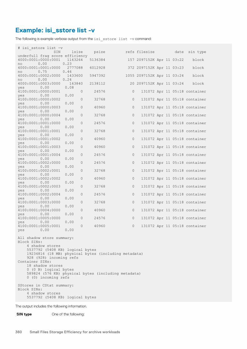
Example: isi_sstore list -vThe following is example verbose output from the isi_sstore list -v command:
# isi_sstore list -v SIN lsize psize refs filesize date sin type underfull frag score efficiency4000:0001:0000:0001 1163264 5136384 157 2097152K Apr 11 03:22 block no 0.00 0.234000:0001:0001:0000 2777088 6012928 372 2097152K Apr 11 03:23 block no 0.75 0.464000:0001:0002:0000 1433600 5947392 1055 2097152K Apr 11 03:24 block no 0.00 0.244000:0001:0003:0000 163840 2138112 20 2097152K Apr 11 03:24 block yes 0.00 0.084100:0001:0000:0001 0 24576 0 131072 Apr 11 05:18 container yes 0.00 0.004100:0001:0000:0002 0 32768 0 131072 Apr 11 05:18 container yes 0.00 0.004100:0001:0000:0003 0 40960 0 131072 Apr 11 05:18 container yes 0.00 0.004100:0001:0000:0004 0 32768 0 131072 Apr 11 05:18 container yes 0.00 0.004100:0001:0001:0000 0 24576 0 131072 Apr 11 05:18 container yes 0.00 0.004100:0001:0001:0001 0 32768 0 131072 Apr 11 05:18 container yes 0.00 0.004100:0001:0001:0002 0 40960 0 131072 Apr 11 05:18 container yes 0.00 0.004100:0001:0001:0003 0 40960 0 131072 Apr 11 05:18 container yes 0.00 0.004100:0001:0001:0004 0 24576 0 131072 Apr 11 05:18 container yes 0.00 0.004100:0001:0002:0000 0 24576 0 131072 Apr 11 05:18 container yes 0.00 0.004100:0001:0002:0001 0 32768 0 131072 Apr 11 05:18 container yes 0.00 0.004100:0001:0002:0002 0 40960 0 131072 Apr 11 05:18 container yes 0.00 0.004100:0001:0002:0003 0 32768 0 131072 Apr 11 05:18 container yes 0.00 0.004100:0001:0002:0004 0 24576 0 131072 Apr 11 05:18 container yes 0.00 0.004100:0001:0003:0000 0 32768 0 131072 Apr 11 05:18 container yes 0.00 0.004100:0001:0004:0000 0 40960 0 131072 Apr 11 05:18 container yes 0.00 0.004100:0001:0005:0000 0 24576 0 131072 Apr 11 05:18 container yes 0.00 0.004100:0001:0005:0001 0 40960 0 131072 Apr 11 05:18 container yes 0.00 0.00
All shadow store summary:Block SINs: 4 shadow stores 5537792 (5408 KB) logical bytes 19234816 (18 MB) physical bytes (including metadata) 928 (928) incoming refsContainer SINs: 18 shadow stores 0 (0 B) logical bytes 589824 (576 KB) physical bytes (including metadata) 0 (0) incoming refs
SStores in CStat summary:Block SINs: 4 shadow stores 5537792 (5408 KB) logical bytes
The output includes the following information.
SIN type One of the following:
360 Small Files Storage Efficiency for archive workloads

• block—the shadow store is used for dedupe or clone operations.• container—the shadow store is used for packing operations.
underfull flag If yes, the container is too small to provide storage savings benefits.
frag score A measure of the level of fragmentation in the shadow store. Higher numbers mean more fragmentation.
The value is the ratio of the sparse blocks in partially allocated stripes to the total size of all stripes containingdata.
efficiency score A ratio of the logical size of the shadow store versus the physical size required to store it (including protectionoverhead). Higher numbers are better but there will be a limit based on the protection level in use by the shadowstores.
Example: isi_sstore statsThe following is example output from the isi_sstore stats command.
# isi_sstore stats Block SIN stats:6 MB user data takes 3 MB in shadow stores, using 6 MB physical space.280K physical average per shadow store.
2 refs per block.Reference efficiency 50%.Storage efficiency 200%
Container SIN stats:3 MB user data takes 3 MB in shadow stores, using 4 MB physical space.3984K physical average per shadow store.
1 refs per block.Reference efficiency 0%.Storage efficiency 100%Raw counts={ type 0 num_ss=20 lsize=3055616 pblk=715 refs=1119 }{ type 1 num_ss=1 lsize=2654208 pblk=498 refs=648 }
The first set of statistics is for a shadow store that contains cloned data. The Storage efficiency of 200% means that every twofiles consume one file space after cloning.
The second set of statistics is for a shadow store that contains packed data. Because packed data is single-referenced, its Storageefficiency is 100% and its Reference efficiency is 0% (that is, no block sharing).
The Raw counts field at the end of the output contains the following statistics:
num_ss The number of ShadowStores.
lsize Logical size of data contained in the ShadowStores.
pblk Number of physical blocks.
refs Number of incoming block references for the shadow store.
isi_sstore defragRuns ShadowStore defragmentation on a node.
UsageThis command runs on a single node and iterates through all shadow stores serially. The command starts by retrieving thedefragmentation global configuration from gconfig and then resets all of the boolean options to false. Use command line options toenable (re-enable) each of the options as needed.
Syntax
isi_sstore defrag [-a] [-b] [-c] [-d] [-e percent]
Small Files Storage Efficiency for archive workloads 361

[-h] [-l level] [-p] [-s] [-v] [-z size][sins]
Options-a
Runs the shadow store defragmenter in assessment mode.
Assessment mode generates an estimate of the disk space savings that could occur with defragmentationwithout actually performing the defragmentation. This mode does not move any data or make any other on-diskchanges. This is a quick operation that can be used to determine if the defragmentation feature should be fullyenabled. The assessment mode must be turned off for the defragmentation process to do any actual work.
-b
Runs the defragmenter against block-based stores.
BSINs are block-based shadow stores, which are stores used by clone and dedupe operations. Thedefragmentation process on BSINs can be intensive and may take some time.
-c
Runs the defragmenter against containers.
CSINs are small file storage efficiency containers.
-d
Enables defragmentation. This option is always required, even when running the defragmenter in assessmentmode.
-e percent
Sets the target efficiency percentage.
The target_efficiency determines the minimum acceptable storage efficiency relative to the maximumstorage efficiency achievable by the shadow store based on its current protection level.
A target of 90% is relatively easy to achieve with a large cluster. The value can be set even higher. Smallerclusters, such as a 3-node cluster, may perform better with a lower target, such as 80%.
The percent is a whole number. If a fraction is specified, the digits after the decimal point are ignored.
The installed global configuration value is 90.
For example: -e 95-h
Displays the command help.
-l level
This parameter is currently not used.
-p
Enables protection group efficiency.
This is a compaction feature. When enabled, this option attempts to reduce the number of protection groupsneeded by the shadow stores, which in turn reduces restripe time.
-s
Determines whether the defragmenter examines snapshot files for references to the shadow store beingdefragged. Consider the following:
• When this option is disabled, if snapshot files contain references to shadow store blocks that need to bedefragmented, the defragmenter can not move those blocks and the shadow store may remain fragmented.
• When this option is enabled, it can add significant processing overhead for clusters with many snapshots.
Depending on your workflow, it may be preferable to run the defragmenter most frequently without examiningfiles from snapshots, with occasional runs that include the snapshot files.
-v
Sets the output to verbose.
-z size
Sets the defragmentation chunk size, in bytes. The chunk size is the size of each region in the shadow store thatis independently evaluated for defragmentation. The optimal size depends on your workflow.
362 Small Files Storage Efficiency for archive workloads

• Setting a value greater than the size of the shadow store (for example, 2GB), forces the entire shadow storeto be defragmented only when the efficiency of the entire store is degraded.
• Setting a small value (for example, 1MB) achieves more aggressive gains.
The installed global configuration value is 33554432 which is 32MB. This setting works well in most scenarios.
sins
Provide an optional list of SINs, separated with spaces, on which to apply this command. The default is to includeall SINs.
Examples
Example of isi_sstore defrag -d -bThe following is sample output for isi_sstore defrag -d -b . The command runs the defragmenter on all BSINs without movingfiles in snapshots.
# isi_sstore defrag -d -b Summary: Shadows stores total: 1 Shadows stores processed: 1 Shadows stores with error: 0 Chunks needing defrag: 1 Estimated space savings: 8192K Files moved: 2 Files repacked: 0 Files missing: 0 Files skipped: 0 Blocks needed: 3072 Blocks rehydrated: 4096 Blocks deduped: 2048 Blocks freed: 4096 Shadows stores removed: 1
Example of isi_sstore defrag -d -a -b -vThe following is sample output for isi_sstore defrag -d -a -b -v . The command runs the shadow store defragmenter inassessment mode. The output shows the disk space that would be reclaimed by defragmenting all block-based shadow stores.
# isi_sstore defrag -d -a -b -vConfiguration: Defrag enabled: 1 BSINs enabled: 1 CSINs enabled: 0 Chunk size: 33554432 Target efficiency: 90 PG efficiency: 0 Snapshots enabled: 0 Log level: 5Summary: Shadows stores total: 1 Shadows stores processed: 1 Shadows stores skipped: 0 Shadows stores with error: 0 Chunks needing defrag: 1 Estimated space savings: 8192K
Example with a SIN listThe following command requests defragmentation on a list of SINs.
# isi_sstore defrag -v -d -a -c -p 4000:0001:0000:0001 4000:0001:0000:0002 4000:0001:0000:0003
Small Files Storage Efficiency for archive workloads 363

4000:0001:0000:0004 4000:0001:0000:0005
isi_storage_efficiencyCalculates storage efficiency on small, sample data sets.
UsageThe isi_storage_efficiency debugging script recursively scans through a directory and calculates the storage efficiency of files inthe sample data set, taking into account the use of ShadowStores. This script runs out of memory if you run it on large data sets.
NOTE: The Unix du command does not show accurate usage for files with shadow references, including packed files.
Syntax
isi_storage_efficiency <path>
Optionspath
Path name of directory to scan.
Storage efficiency exampleThe following example shows the storage efficiency of a small file data set, /ifs/data/my_small_files, before and after packing.Before packing, the storage efficiency is 33%. After packing, storage efficiency is 65.5%.
# isi_storage_efficiency /ifs/data/my_small_files Mode Count Logical data size Size Blocks DIR 1 0 48045 964 REG 2048 134217728 134217728 792576
Storage efficiencyFile data 0.330749354005File logical data 0.330749354005 Overall 0.330465808769Overall logical 0.330347556519
Now, assume that the following activities have occurred:
• A FilePools policy that selects /ifs/data/my_small_files is enabled
• A SmartPools job has run.
Rerunning the report shows improved storage efficiency.
# isi_storage_efficiency /ifs/data/my_small_files Mode Count Logical data size Size Blocks DIR 1 0 48045 964 REG 2048 134217728 134217728 6144 SIN 1 134217728 167075840 394227Shadow store usage may be affected by the ShadowStoreDelete job.
Storage efficiencyFile data 0.654752716855File logical data 0.654752716855 Overall 0.653413826082Overall logical 0.653180011711
364 Small Files Storage Efficiency for archive workloads

Troubleshooting Small Files Storage EfficiencyPossible issues generally fall into the following categories.
Performance I/O efficiency, fragmentation, and packing can affect performance.
Space Unpacking or expanding clones, packed files, and deduplicated files require sufficient available space.
Following are suggestions for investigating these issues.
Log filesTo locate container ShadowStores that might be affected by storage efficiency problems, look for the following types of information inthe logs.
Module name Look for the value SFM.
SIN ID prefix Container shadow stores (CSINs) that contain packed data have the prefix 0x41.
File pack state Values are complete or incomplete.
Packing policy andpacking target
Values are native or container.
For information about file attributes, see File system structure on page 346.
Fragmentation issuesFragmentation affects space usage and is the most common storage efficiency issue.
If files are overwritten or deleted repeatedly, there can be fragmentation in the container ShadowStores.
The following commands provide information about fragmentation:
• isi_sstore defrag -v -d -a -c -p shows the fragmentation space that defragmentation can reclaim.
• isi_packing --ls shows the current packing configuration.
• SmartPools job reports in verbose mode shows statistics about files that were packed.• isi_sstore list and isi_sstore stats show the degree of fragmentation. Use isi_sstore list -v to see the
fragmentation score and other verbose attributes for each SIN entry.• isi_storage_efficiency scans through a directory or files and calculates the storage efficiency of files in the sample data set.
• isi get shows file attributes, including packing attributes.
• isi_cprSee the Isilon OneFS CLI Command Reference for information about isi get. The reference pages for the commands related to SmallFiles Storage Efficiency are here.
The ShadowStoreDelete job frees up blocks for the shadow store and runs the defragmenter if it is enabled.
Be aware of how much space you have packed. Clones, packed files, and deduplicated files are unpacked or expanded on the targetcluster during SyncIQ operations and have to be re-packed or re-deduplicated on the target cluster.
Small Files Storage Efficiency for archive workloads 365

NetworkingThis section contains the following topics:
Topics:
• Networking overview• About the internal network• About the external network• Managing internal network settings• Managing groupnets• Managing external network subnets• Managing IP address pools• Managing SmartConnect Settings• Managing connection rebalancing• Managing network interface members• Managing node provisioning rules• Managing routing options• Managing DNS cache settings
Networking overviewAfter you determine the topology of your network, you can set up and manage your internal and external networks.
There are two types of networks on a cluster:
Internal Nodes communicate with each other using a high speed low latency InfiniBand network. You can optionallyconfigure a second InfiniBand network to enable failover for redundancy.
External Clients connect to the cluster through the external network with Ethernet. The Isilon cluster supports standardnetwork communication protocols, including NFS, SMB, HDFS, HTTP, and FTP. The cluster includes variousexternal Ethernet connections, providing flexibility for a wide variety of network configurations.
About the internal networkA cluster must connect to at least one high-speed, low-latency InfiniBand switch for internal communications and data transfer. Theconnection to the InfiniBand switch is also referred to as an internal network. The internal network is separate from the external network(Ethernet) by which users access the cluster.
Upon initial configuration of your cluster, OneFS creates an initial internal network for the InfiniBand switch. The interface to the defaultinternal network is int-a. An internal network for a second InfiniBand switch can be added for redundancy and failover. Failover allowscontinuous connectivity during path failures. The interface to the secondary internal network is int-b, which is referred to as int-b/failoverin the web administration interface.
CAUTION: Only Isilon nodes should be connected to your InfiniBand switch. Information exchanged on the back-end
network is not encrypted. Connecting anything other than Isilon nodes to the InfiniBand switch creates a security risk.
Internal IP address rangesThe number of IP addresses assigned to the internal network determines how many nodes can be joined to the cluster.
When you initially configure the cluster, you specify one or more IP address ranges for the primary InfiniBand switch. This range ofaddresses is used by the nodes to communicate with each other. It is recommended that you create a range of addresses large enough toaccommodate adding additional nodes to your cluster.
30
366 Networking

While all clusters will have, at minimum, one internal InfiniBand network (int-a), you can enable a second internal network to supportanother Infiniband switch with network failover (int-b/failover). You must assign at least one IP address range for the secondary networkand one range for failover.
If any IP address ranges defined during the initial configuration are too restrictive for the size of the internal network, you can add rangesto the int-a network or int-b/failover networks, which might require a cluster restart. Other configuration changes, such as deleting an IPaddress assigned to a node, might also required the cluster to be restarted.
Internal network failoverYou can configure an internal switch as a failover network to provide redundancy for intra-cluster communications.
In order to support an internal failover network, the int-a port on each node in the cluster must be physically connected to one of theInfiniband switches, and the int-b port on each node must be connected to the other Infiniband switch.
After the ports are connected, you must configure two IP address ranges; an address range to support the int-b internal interfaces, and anaddress range to support failover. The failover addresses enable seamless failover in the event that either the int-a or int-b switches fail.
About the external networkYou connect a client computer to the cluster through the external network. External network configuration is composed of groupnets,subnets, IP address pools, and features node provisioning rules.
Groupnets are the configuration level for managing multiple tenants on your external network. DNS client settings, such as nameserversand a DNS search list, are properties of the groupnet. Groupnets reside at the top tier of the networking hierarchy. You can create one ormore subnets within a groupnet.
Subnets simplify external (front-end) network management and provide flexibility in implementing and maintaining the cluster network.You can create IP address pools within subnets to partition your network interfaces according to workflow or node type.
The IP address pool of a subnet consists of one or more IP address ranges. IP address pools can be associated with network interfaces oncluster nodes. Client connection settings are configured at the IP address pool level.
An initial external network subnet is created during the setup of your cluster with the following configuration:
• An initial groupnet called groupnet0 with the specified global, outbound DNS settings to the domain name server list and DNS searchlist, if provided.
• An initial subnet called subnet0 with the specified netmask, gateway, and SmartConnect service address.• An initial IP address pool called pool0 with the specified IP address range, the SmartConnect zone name, and the network interface of
the first node in the cluster as the only pool member.• An initial node provisioning rule called rule0 that automatically assigns the first network interface for all newly added nodes to pool0.• Adds subnet0 to groupnet0.• Adds pool0 to subnet0 and configures pool0 to use the virtual IP of subnet0 as its SmartConnect service address.
GroupnetsGroupnets reside at the top tier of the networking hierarchy and are the configuration level for managing multiple tenants on your externalnetwork. DNS client settings, such as nameservers and a DNS search list, are properties of the groupnet. You can create a separategroupnet for each DNS namespace that you want to use to enable portions of the Isilon cluster to have different networking properties forname resolution. Each groupnet maintains its own DNS cache, which is enabled by default.
A groupnet is a container that includes subnets, IP address pools, and provisioning rules. Groupnets can contain one or more subnets, andevery subnet is assigned to a single groupnet. Each cluster contains a default groupnet named groupnet0 that contains an initial subnetnamed subnet0, an initial IP address pool named pool0, and an initial provisioning rule named rule0.
Each groupnet is referenced by one or more access zones. When you create an access zone, you can specify a groupnet. If a groupnet isnot specified, the access zone will reference the default groupnet. The default System access zone is automatically associated with thedefault groupnet. Authentication providers that communicate with an external server, such as Active Directory and LDAP, must alsoreference a groupnet. You can specify the authentication provider with a specific groupnet; otherwise, the provider will reference thedefault groupnet. You can only add an authentication provider to an access zone if they are associated with the same groupnet. Clientprotocols such as SMB, NFS, HDFS, and Swift, are supported by groupnets through their associated access zones.
Networking 367

DNS name resolutionYou can designate up to three DNS servers per groupnet to handle DNS name resolution.
DNS servers must be configured as an IPv4 or IPv6 address. You can specify up to six DNS search suffixes per groupnet; the suffixessettings are appended to domain names that are not fully qualified.
Additional DNS server settings at the groupnet level include enabling a DNS cache, enabling server-side search, and enabling DNSresolution on a rotating basis.
SubnetsSubnets are networking containers that enable you to sub-divide your network into smaller, logical IP networks.
On a cluster, subnets are created under a groupnet and each subnet contains one or more IP address pools. Both IPv4 and IPv6 addressesare supported on OneFS; however, a subnet cannot contain a combination of both. When you create a subnet, you specify whether itsupports IPv4 or IPv6 addresses.
You can configure the following options when you create a subnet:
• Gateway servers that route outgoing packets and gateway priority.• Maximum transmission unit (MTU) that network interfaces in the subnet will use for network communications.• SmartConnect service address, which is the IP address on which the SmartConnect module listens for DNS requests on this subnet.• VLAN tagging to allow the cluster to participate in multiple virtual networks.• Direct Server Return (DSR) address, if your cluster contains an external hardware load balancing switch that uses DSR.
How you set up your external network subnets depends on your network topology. For example, in a basic network topology where allclient-node communication occurs through direct connections, only a single external subnet is required. In another example, if you wantclients to connect through both IPv4 and IPv6 addresses, you must configure multiple subnets.
IPv6 supportOneFS supports both IPv4 and IPv6 address formats on a cluster.
IPv6 is the next generation of internet protocol addresses and was designed with the growing demand for IP addresses in mind. Thefollowing table describes distinctions between IPv4 and IPv6.
IPv4 IPv6
32-bit addresses 128-bit addresses
Address Resolution Protocol (ARP) Neighbor Discovery Protocol (NDP)
You can configure the Isilon cluster for IPv4, IPv6, or both (dual-stack) in OneFS. You set the IP family when creating a subnet, and all IPaddress pools assigned to the subnet must use the selected format.
VLANsVirtual LAN (VLAN) tagging is an optional setting that enables a cluster to participate in multiple virtual networks.
You can partition a physical network into multiple broadcast domains, or virtual local area networks (VLANs). You can enable a cluster toparticipate in a VLAN which allows multiple cluster subnet support without multiple network switches; one physical switch enables multiplevirtual subnets.
VLAN tagging inserts an ID into packet headers. The switch refers to the ID to identify from which VLAN the packet originated and towhich network interface a packet should be sent.
IP address poolsIP address pools are assigned to a subnet and consist of one or more IP address ranges. You can partition nodes and network interfacesinto logical IP address pools. IP address pools are also utilized when configuring SmartConnect DNS zones and client connectionmanagement.
Each IP address pool belongs to a single subnet. Multiple pools for a single subnet are available only if you activate a SmartConnectAdvanced license.
The IP address ranges assigned to a pool must be unique and belong to the IP address family (IPv4 or IPv6) specified by the subnet thatcontains the pool.
368 Networking

You can add network interfaces to IP address pools to associate address ranges with a node or a group of nodes. For example, based onthe network traffic that you expect, you might decide to establish one IP address pool for storage nodes and another for acceleratornodes.
SmartConnect settings that manage DNS query responses and client connections are configured at the IP address pool level.
Link aggregationLink aggregation, also known as network interface card (NIC) aggregation, combines the network interfaces on a physical node into asingle, logical connection to provide improved network throughput.
You can add network interfaces to an IP address pool singly or as an aggregate. A link aggregation mode is selected on a per-pool basisand applies to all aggregated network interfaces in the IP address pool. The link aggregation mode determines how traffic is balanced androuted among aggregated network interfaces.
SmartConnect moduleSmartConnect is a module that specifies how the DNS server on the cluster handles connection requests from clients and the policies thatare used to assign IP addresses to network interfaces, including failover and rebalancing.
Settings and policies that are configured for SmartConnect are applied per IP address pool. You can configure basic and advancedSmartConnect settings.
SmartConnect BasicSmartConnect Basic is included with OneFS as a standard feature and does not require a license. SmartConnect Basic supports thefollowing settings:
• Specification of the DNS zone• Round-robin connection balancing method only• Service subnet to answer DNS requests
SmartConnect Basic enables you to add two SmartConnect Service IP addresses to a subnet.
SmartConnect Basic has the following limitations to IP address pool configuration:
• You may only specify a static IP address allocation policy.• You cannot specify an IP address failover policy.• You cannot specify an IP address rebalance policy.• You may assign two IP address pools per external network subnet.
SmartConnect AdvancedSmartConnect Advanced extends the settings available from SmartConnect Basic. It requires an active license. SmartConnect Advancedsupports the following settings:
• Round-robin, CPU utilization, connection counting, and throughput balancing methods• Static and dynamic IP address allocation
SmartConnect Advance enables you to add a maximum of six SmartConnect Service IP addresses per subnet.
SmartConnect Advanced enables you to specify the following IP address pool configuration options:
• You can define an IP address failover policy for the IP address pool.• You can define an IP address rebalance policy for the IP address pool.• SmartConnect Advanced supports multiple IP address pools per external subnet to enable multiple DNS zones within a single subnet.
SmartConnect zones and aliasesClients can connect to the cluster through a specific IP address or though a domain that represents an IP address pool.
You can configure a SmartConnect DNS zone name for each IP address pool. The zone name must be a fully qualified domain name.SmartConnect requires that you add a new name server (NS) record that references the SmartConnect service IP address in the existingauthoritative DNS zone that contains the cluster. You must also provide a zone delegation to the fully qualified domain name (FQDN) ofthe SmartConnect zone in your DNS infrastructure.
If you have a SmartConnect Advanced license, you can also specify a list of alternate SmartConnect DNS zone names for the IP addresspool.
Networking 369

When a client connects to the cluster through a SmartConnect DNS zone, SmartConnect handles the incoming DNS requests on behalfof the IP address pool, and the service subnet distributes incoming DNS requests according to the pool's connection balancing policy.
DNS request handlingSmartConnect handles all incoming DNS requests on behalf of an IP address pool if a SmartConnect service subnet has been associatedwith the pool.
The SmartConnect service subnet is an IP address pool setting. You can specify any subnet that has been configured with aSmartConnect service IP address and references the same groupnet as the pool. You must have at least one subnet configured with aSmartConnect service IP address in order to handle client DNS requests. You can configure only one service IP address per subnet.
A SmartConnect service IP address should be used exclusively for answering DNS requests and cannot be an IP address that is in anypool's IP address range. Client connections through the SmartConnect service IP address result in unexpected behavior or disconnection.
Once a SmartConnect service subnet has been associated with an IP address pool, the service subnet distributes incoming DNS requestsaccording to the pool's connection balancing policy. If a pool does not have a designated service subnet, incoming DNS requests areanswered by the subnet that contains the pool, provided that the subnet is configured with a SmartConnect service IP address.Otherwise, the DNS requests are excluded.
NOTE: SmartConnect requires that you add a new name server (NS) record that references the SmartConnect service
IP address in the existing authoritative DNS zone that contains the cluster. You must also provide a zone delegation to
the fully qualified domain name (FQDN) of the SmartConnect zone.
IP address allocationThe IP address allocation policy specifies how IP addresses in the pool are assigned to an available network interface.
You can specify whether to use static or dynamic allocation.
Static Assigns one IP address to each network interface added to the IP address pool, but does not guarantee that all IPaddresses are assigned.
Once assigned, the network interface keeps the IP address indefinitely, even if the network interface becomesunavailable. To release the IP address, remove the network interface from the pool or remove it from the node.
Without a license for SmartConnect Advanced, static is the only method available for IP address allocation.
Dynamic Assigns IP addresses to each network interface added to the IP address pool until all IP addresses are assigned.This guarantees a response when clients connect to any IP address in the pool.
If a network interface becomes unavailable, its IP addresses are automatically moved to other available networkinterfaces in the pool as determined by the IP address failover policy.
This method is only available with a license for SmartConnect Advanced.
IP address failoverWhen a network interface becomes unavailable, the IP address failover policy specifies how to handle the IP addresses that were assignedto the network interface.
To define an IP address failover policy, you must have a license for SmartConnect Advanced, and the IP address allocation policy must beset to dynamic. Dynamic IP allocation ensures that all of the IP addresses in the pool are assigned to available network interfaces.
When a network interface becomes unavailable, the IP addresses that were assigned to it are redistributed to available network interfacesaccording to the IP address failover policy. Subsequent client connections are directed to the new network interfaces.
You can select one of the following connection balancing methods to determine how the IP address failover policy selects which networkinterface receives a redistributed IP address:
• Round-robin• Connection count• Network throughput• CPU usage
Connection balancingThe connection balancing policy determines how the DNS server handles client connections to the cluster.
You can specify one of the following balancing methods:
370 Networking

Round-robin Selects the next available network interface on a rotating basis. This is the default method. Without aSmartConnect license for advanced settings, this is the only method available for load balancing.
Connection count Determines the number of open TCP connections on each available network interface and selects the networkinterface with the fewest client connections.
Networkthroughput
Determines the average throughput on each available network interface and selects the network interface withthe lowest network interface load.
CPU usage Determines the average CPU utilization on each available network interface and selects the network interfacewith lightest processor usage.
IP address rebalancingThe IP address rebalance policy specifies when to redistribute IP addresses if one or more previously unavailable network interfacesbecomes available again.
To define an IP address rebalance policy, you must have a license for SmartConnect Advanced, and the IP address allocation policy mustbe set to dynamic. Dynamic IP addresses allocation ensures that all of the IP addresses in the pool are assigned to available networkinterfaces.
You can set rebalancing to occur manually or automatically:
Manual Does not redistribute IP addresses until you manually start the rebalancing process.
Upon rebalancing, IP addresses will be redistributed according to the connection balancing method specified bythe IP address failover policy defined for the IP address pool.
Automatic Automatically redistributes IP addresses according to the connection balancing method specified by the IPaddress failover policy defined for the IP address pool.
Automatic rebalancing may also be triggered by changes to cluster nodes, network interfaces, or the configurationof the external network.
NOTE: Rebalancing can disrupt client connections. Ensure the client workflow on the IP address
pool is appropriate for automatic rebalancing.
Node provisioning rulesNode provisioning rules specify how new nodes are configured when they are added to a cluster.
If the new node type matches the type defined in a rule, the network interfaces on the node are added to the subnet and the IP addresspool specified in the rule.
For example, you can create a node provisioning rule that configures new Isilon storage nodes, and another rule that configures newaccelerator nodes.
OneFS automatically checks for multiple provisioning rules when new rules are added to ensure there are no conflicts.
Routing optionsOneFS supports source-based routing and static routes which allow for more granular control of the direction of outgoing client traffic onthe cluster.
If no routing options are defined, by default, outgoing client traffic on the cluster is routed through the default gateway, which is thegateway with the lowest priority setting on the node. If traffic is being routed to a local subnet and does not need to route through agateway, the traffic will go directly out through an interface on that subnet.
Source-based routingSource-based routing selects which gateway to direct outgoing client traffic through based on the source IP address in each packetheader.
When enabled, source-based routing automatically scans your network configuration to create client traffic rules. If you makemodifications to your network configuration, such as changing the IP address of a gateway server, source-based routing adjusts the rules.Source-based routing is applied across the entire cluster and does not support the IPv6 protocol.
In the following example, you enable source-based routing on an Isilon cluster that is connected to SubnetA and SubnetB. Each subnet isconfigured with a SmartConnect zone and a gateway, also labeled A and B. When a client on SubnetA makes a request to SmartConnect
Networking 371

ZoneB, the response originates from ZoneB. This results in a ZoneB address as the source IP in the packet header, and the response isrouted through GatewayB. Without source-based routing, the default route is destination-based, so the response is routed throughGatewayA.
In another example, a client on SubnetC, which is not connected to the Isilon cluster, makes a request to SmartConnect ZoneA andZoneB. The response from ZoneA is routed through GatewayA, and the response from ZoneB is routed through GatewayB. In otherwords, the traffic is split between gateways. Without source-based routing, both responses are routed through the same gateway.
Source-based routing is disabled by default. Enabling or disabling source-based routing goes into effect immediately. Packets in transitcontinue on their original courses, and subsequent traffic is routed based on the status change. Transactions composed of multiplepackets might be disrupted or delayed if the status of source-based routing changes during transmission.
Source-based routing can conflict with static routes. If a routing conflict occurs, source-based routing rules are prioritized over the staticroute.
You might enable source-based routing if you have a large network with a complex topology. For example, if your network is a multi-tenantenvironment with several gateways, traffic is more efficiently distributed with source-based routing.
Static routingA static route directs outgoing client traffic to a specified gateway based on the IP address of the client connection.
You configure static routes by IP address pool, and each route applies to all nodes that have network interfaces as IP address poolmembers.
You might configure static routing in order to connect to networks that are unavailable through the default routes or if you have a smallnetwork that only requires one or two routes.
NOTE: If you have upgraded from a version earlier than OneFS 7.0.0, existing static routes that were added through rc
scripts will no longer work and must be re-created.
Managing internal network settingsYou can modify internal IP address ranges and configure an Infiniband switch for failover.
Add or remove an internal IP address rangeYou can configure IP address ranges for the int-a, int-b, and failover networks.
Each internal Infiniband switch requires an IP address range. The ranges should have a sufficient number of IP addresses for presentoperating conditions as well as future expansion and addition of nodes.
1. Run the isi config command.The command-line prompt changes to indicate that you are in the isi config subsystem.
2. Modify the internal IP address ranges by running the iprange command.The following command adds an IP range to the int-a internal network:
iprange int-a 192.168.206.10-192.168.206.20
The following command deletes an existing IP address range from the int-a internal network:
deliprange int-a 192.168.206.15-192.168.206.203. Run the commit command to complete the configuration changes and exit isi config.
Modify an internal network netmaskYou can modify the subnet mask, or netmask, value for the int-a and int-b internal network interfaces.
If the netmask is too restrictive for the size of the internal network, you must modify the netmask settings. It is recommended that youspecify a class C netmask, such as 255.255.255.0, for the internal netmask, that is large enough to accommodate future growth of yourIsilon clusters.
It is recommended that the netmask values you specify for int-a and int-b/failover are the same. If you modify the netmask value of one,modify the other.
NOTE: You must reboot the cluster to apply modifications to the netmask.
372 Networking

1. Run the isi config command.The command-line prompt changes to indicate that you are in the isi config subsystem.
2. Modify the internal network netmask by running the netmask command.The following command changes the int-a internal network netmask:
netmask int-a 255.255.255.0
The system displays output similar to the following example:
!! WARNING: The new netmask will not take effect until the nodes are rebooted.3. Run the commit command to complete the configuration changes and exit isi config.
Configure and enable internal network failoverYou can configure the int-b internal interfaces to provide backup in the event of an int-a network failure.
Failover configuration involves enabling the int-b interface, specifying a valid netmask, and adding IP address ranges for the int-b interfaceand the failover network. By default, the int-b interface and failover network are disabled.
NOTE: You must reboot the cluster to apply modifications to internal network failover.
1. Run the isi config command.The command-line prompt changes to indicate that you are in the isi config subsystem.
2. Set a netmask for the second interface by running the netmask command.The following command changes the int-b internal network netmask:
netmask int-b 255.255.255.0
The system displays output similar to the following example:
!! WARNING: The new netmask will not take effect until the nodes are rebooted.3. Set an IP address range for the second interface by running the iprange command.
The following command adds an IP range to the int-b internal network:
iprange int-b 192.168.206.21-192.168.206.304. Set an IP address range for the failover interface by running the iprange command.
The following command adds an IP range to the internal failover network:
iprange failover 192.168.206.31-192.168.206.405. Enable a second interface by running the interface command.
The following command specifies the interface name as int-b and enables it:
interface int-b enable6. Run the commit command to complete the configuration changes and exit isi config.
7. Restart the cluster to apply netmask modifications.
Disable internal network failoverYou can disable internal network failover by disabling the int-b interface.
You must reboot the cluster to apply modifications to internal network failover.
1. Run the isi config command.The command-line prompt changes to indicate that you are in the isi config subsystem.
2. Disable the int-b interface by running the interface command.The following command specifies the int-b interface and disables it:
interface int-b disable3. Run the commit command to complete the configuration changes and exit isi config.
4. Restart the cluster to apply failover modifications.
Networking 373

Managing groupnetsYou can create and manage groupnets on a cluster.
Create a groupnetYou can create a groupnet and configure DNS client settings.
Run the isi network groupnet create command.The following command creates a groupnet named groupnet1 that supports two DNS servers, which are specified by IPv6 addresses:
isi network groupnet create groupnet1 \--dns-servers=2001:DB8:170:9904::be06,2001:DB8:170:9904::be07
The following command creates a groupnet named groupnet1 that supports one DNS server, which is specified by an IPv4 address, andenables DNS caching:
isi network groupnet create groupnet1 \--dns-servers=192.0.2.0 --dns-cache-enabled=true
Modify a groupnetYou can modify groupnet attributes including the name, supported DNS servers, and DNS configuration settings.
Run the isi network groupnet modify command.The following command modifies groupnet1 to enable DNS search on three suffixes:
isi network groupnet modify groupnet1 \--dns-search=data.company.com,storage.company.com
The following command modifies groupnet1 to support a second DNS server and to enable rotation through the configured DNS resolvers:
isi network groupnet modify groupnet1 \--add-dns-servers=192.0.2.1 --dns-options=rotate
Delete a groupnetYou can delete a groupnet from the system, unless it is the default groupnet. If the groupnet is associated with an access zone, anauthentication provider, removal from the system might affect several other areas of OneFS and should be performed with caution.
In several cases, the association between a groupnet and another OneFS component, such as access zones or authentication providers, isabsolute. You cannot modify these components to associate them with another groupnet.
In the event that you need to delete a groupnet, we recommend that you complete the these tasks in the following order:
1. Delete IP address pools in subnets associated with the groupnet.2. Delete subnets associated with the groupnet.3. Delete authentication providers associated with the groupnet.4. Delete access zones associated with the groupnet.
1. Run the isi network groupnet delete command..
2. At the prompt to confirm deletion, type yes.The following command deletes a groupnet named groupnet1:
isi network groupnet delete groupnet1
The following command attempts to delete groupnet1, which is still associated with an access zone:
isi network modify groupnet groupnet1
The system displays output similar to the following example:
374 Networking

Groupnet groupnet1 is not deleted; groupnet can't be deleted while pointed at by zone(s) zoneB
View groupnetsYou can retrieve and sort a list of all groupnets on the system and view the details of a specific groupnet.
1. To retrieve a list of groupnets in the system, run the isi network groupnets list command.The following command sorts the list of groupnets by ID in descending order:
isi network groupnets list --sort=id --descending
The system displays output similar to the following example:
ID DNS Cache DNS Search DNS Servers Subnets------------------------------------------------------------groupnet2 True data.company.com 192.0.2.75 subnet2 192.0.2.67 subnet4groupnet1 True 192.0.2.92 subnet1 192.0.2.83 subnet3groupnet0 False 192.0.2.11 subnet0 192.0.2.20--------Total: 3
2. To view the details of a specific groupnet, run the isi network groupnets view command.The following command displays the details of a groupnet named groupnet1:
isi network groupnets view groupnet1
The system displays output similar to the following example:
ID: groupnet1 Name: groupnet1 Description: Data storage groupnet DNS Cache Enabled: True DNS Options: - DNS Search: data.company.com DNS Servers: 192.0.1.75, 10.7.2.67Server Side DNS Search: True Subnets: subnet1, subnet3
Managing external network subnetsYou can create and manage subnets on a cluster.
Create a subnetYou can add a subnet to the external network of a cluster.
Subnets must be associated with a groupnet. Ensure that the groupnet you want to associate with this subnet exists in the system.
An IP address family designation and prefix length are required when creating a subnet.
Run the isi network subnets create command and specify a subnet ID, IP address family, and prefix length.
Specify the subnet ID you want to create in the following format:
<groupnet_name>.<subnet_name>
The subnet name must be unique in the system.
The following command creates a subnet associated with groupnet1, designates the IP address family as IPv4 and specifies an IPv4 prefixlength:
isi network subnets create \ groupnet1.subnet3 ipv4 255.255.255.0
Networking 375

The following command creates a subnet with an associated IPv6 prefix length:
isi network subnets create \ groupnet1.subnet3 ipv6 64
Modify a subnetYou can modify a subnet on the external network.
NOTE: Modifying an external network subnet that is in use can disable access to the cluster.
1. Optional: To identify the ID of the external subnet you want to modify, run the following command:
isi network subnets list2. Run the isi networks modify subnet command
Specify the subnet ID you want to modify in the following format:
<groupnet_name>.<subnet_name>
The following command changes the name of subnet3 under groupnet1 to subnet5:
isi network subnets modify groupnet1.subnet3 \ --name=subnet5
The following command sets the MTU to 1500, specifies the gateway address as 198.162.205.10, and sets the gateway priority to 1:
isi network subnets modify groupnet1.subnet3 --mtu=1500 --gateway=198.162.205.10 --gateway-priority=1
Delete a subnetYou can delete an external network subnet that you no longer need.
NOTE: Deleting an external network subnet also deletes any associated IP address pools. Deleting a subnet that is in use
can prevent access to the cluster.
1. Optional: To identify the name of the subnet you want to delete, run the following command:
isi network subnets list
2. Run the isi networks delete subnet command.
Specify the subnet ID you want to delete in the following format:
<groupnet_name>.<subnet_name>
The following command deletes subnet3 under groupnet1:
isi network subnets delete groupnet1.subnet33. At the prompt, type yes.
View subnetsYou can view all subnets on the external network, sort subnets by specified criteria, or view details for a specific subnet.
1. To view all subnets, run the isi network subnets list command.
The system displays output similar to the following example:
ID Subnet Gateway|Priority Pools SC Service----------------------------------------------------------------------groupnet1.subnet0 203.0.113.10/24 203.0.113.12|1 pool0 198.51.100.10
376 Networking

groupnet1.subnet3 192.0.2.20/24 192.0.2.22|2 pool3 198.51.100.15----------------------------------------------------------------------
2. To view the details of a specific subnet, run the isi network subnets view command and specify the subnet ID.
Specify the subnet ID you want to view in the following format:
<groupnet_name>.<subnet_name>
The following command displays details for subnet3 under groupnet1:
isi network subnets view groupnet1.subnet3
The system displays output similar to the following example:
ID: groupnet1.subnet3 Name: subnet3 Groupnet: groupnet1 Pools: pool3 Addr Family: ipv4 Base Addr: 192.0.2.20 CIDR: 192.0.2.20/24 Description: Sales subnet Dsr Addrs: - Gateway: 192.0.2.22Gateway Priority: 2 MTU: 1500 Prefixlen: 24 Netmask: 255.255.255.0 Sc Service Addr: 198.51.100.15 VLAN Enabled: False VLAN ID: -
Configure a SmartConnect service IP addressYou can specify a SmartConnect service IP address on a subnet.
1. Optional: To identify the name of the external subnet you want to modify, run the following command:
isi network subnets list
2. Run the isi networks modify subnet command
Specify the subnet ID you want to modify in the following format:
<groupnet_name>.<subnet_name>
The following command specifies the SmartConnect service IP address on subnet3 under groupnet1:
isi network subnets modify groupnet1.subnet3 \ --sc-service-addr=198.51.100.15
Assign this subnet to one or more IP address pools in order to handle DNS requests for those pools.
Enable or disable VLAN taggingYou can partition the external network into Virtual Local Area Networks or VLANs.
VLAN tagging requires a VLAN ID that corresponds to the ID number for the VLAN set on the switch. Valid VLAN IDs are 2 to 4094.
1. Optional: To identify the name of the external subnet you want to modify for VLAN tagging, run the following command:
isi network subnets list
2. Enable or disable VLAN tagging on the external subnet by running the isi networks modify subnet command.
Networking 377

Specify the subnet ID you want to modify in the following format:
<groupnet_name>.<subnet_name>
The following command enables VLAN tagging on subnet3 under groupnet1 and sets the required VLAN ID to 256:
isi network subnets modify groupnet1.subnet3 \ --vlan-enabled=true --vlan-id=256
The following command disables VLAN tagging on subnet3 under groupnet1:
isi network subnets modify groupnet1.subnet3 \ --vlan-enabled=false
3. At the prompt, type yes.
Add or remove a DSR addressYou can specify a Direct Server Return (DSR) address for a subnet if your cluster contains an external hardware load balancing switchthat uses DSR.
1. Optional: To identify the name of the external subnet you want to modify for DRS addresses, run the following command:
isi network subnets list
2. Run the isi network subnets modify command.
Specify the subnet ID you want to modify in the following format:
<groupnet_name>.<subnet_name>
The following command adds a DSR address to subnet3 under groupnet1:
isi network subnets modify groupnet1.subnet3 \ --add-dsr-addrs=198.51.100.20
The following command removes a DSR address from subnet3 under groupnet1:
isi network subnets modify groupnet1.subnet3 \ --remove-dsr-addrs=198.51.100.20
Managing IP address poolsYou can create and manage IP address pools on the cluster.
Create an IP address poolYou can partition the external network interface into groups, or pools, of unique IP address ranges.
NOTE: If you have not activated a SmartConnect Advanced license, the cluster is allowed one IP address pool per
subnet. If you activate a SmartConnect Advanced license, the cluster is allowed unlimited IP address pools per subnet.
When you create an address pool, you must assign it to a subnet. If the subnet is not under the default groupnet, groupnet0, then youmust also assign an access zone to the pool.
Run the isi network pools create command.
Specify the ID of the pool you want to create in the following format:
<groupnet_name>.<subnet_name>.<pool_name>
378 Networking

The following command creates a pool named pool5 and assigns it to subnet3 under groupnet1:
isi network pools create groupnet1.subnet3.pool5
The following command creates a pool named pool5, assigns it to groupnet1.subnet3, and specifies zoneB as the access zone:
isi network pools create groupnet1.subnet3.pool5 \ --access-zone=zoneB
Modify an IP address poolYou can modify IP address pools to update pool settings.
1. Optional: To identify the name of the IP address pool you want to modify, run the following command:
isi network pools list
2. Run the isi networks modify pool command.
Specify the pool ID you want to modify in the following format:
<groupnet_name>.<subnet_name>.<pool_name>
The following command changes the name of the pool from pool3 to pool5:
isi network pools modify groupnet1.subnet3.pool3 --name=pool5
Delete an IP address poolYou can delete an IP address pool that you no longer need.
When a pool is deleted, the pool and pool settings are removed from the assigned subnet.
1. Optional: To identify the name of the IP address pool you want to delete, run the following command:
isi network pools list
2. Run the isi networks delete pool command.
Specify the pool ID you want to delete in the following format:
<groupnet_name>.<subnet_name>.<pool_name>
The following command deletes the pool name pool5 from groupnet1.subnet3:
isi network pools delete groupnet1.subnet3.pool53. At the prompt, type yes.
View IP address poolsYou can view all IP address pools within a groupnet or subnet, sort pools by specified criteria, or view details for a specific pool.
1. To view all IP address pools within a groupnet or subnet, run the isi network pools list command.The following command displays all IP address pools under groupnet1.subnet3:
isi network pools list groupnet1.subnet3
The system displays output similar to the following example:
ID SC Zone Allocation Method----------------------------------------------------------groupnet1.subnet3.pool5 data.company.com static
Networking 379

groupnet1.subnet3.pool7 data.company.com dynamic----------------------------------------------------------
2. To view the details of a specific IP address pool, run the isi network pools view command and specify the pool ID.
Specify the pool ID you want to view in the following format:
<groupnet_name>.<subnet_name>.<pool_name>
The following command displays the setting details of pool5 under groupnet1.subnet3:
isi network pools view groupnet1.subnet3.pool5
The system displays output similar to the following example:
ID: groupnet0.subnet3.pool5 Groupnet: groupnet1 Subnet: subnet3 Name: pool5 Rules: - Access Zone: zone3 Allocation Method: static Aggregation Mode: lacp SC Suspended Nodes: - Description: - Ifaces: 1:ext-2, 2:ext-2, 3:ext-2 IP Ranges: 203.0.223.12-203.0.223.22 Rebalance Policy: autoSC Auto Unsuspend Delay: 0 SC Connect Policy: round_robin SC Zone: data.company.com SC DNS Zone Aliases: - SC Failover Policy: round_robin SC Subnet: groupnet0.subnet3 SC Ttl: 0 Static Routes: -
Add or remove an IP address rangeYou can configure a range of IP addresses for a pool.
All IP address ranges in a pool must be unique.
1. Optional: To identify the name of the IP address pool you want to modify for IP address ranges, run the following command:
isi network pools list
2. Run the isi network pools modify command.
Specify the pool ID you want to modify in the following format:
<groupnet_name>.<subnet_name>.<pool_name>
The following command adds an address range to pool5 under groupnet1.subnet3:
isi network pools modify groupnet1.subnet3.pool5 \ --add-ranges=203.0.223.12-203.0.223.22
The following command deletes an address range from pool5:
isi network pools modify groupnet1.subnet3.pool5 \ --remove-ranges=203.0.223.12-203.0.223.14
380 Networking

Configure IP address allocationYou can specify whether the IP addresses in an IP address pool are allocated to network interfaces statically or dynamically.
To configure dynamic IP address allocation, you must activate a SmartConnect Advanced license.
1. Optional: To identify the name of the IP address pool you want to modify, run the following command:
isi network pools list
2. Run the isi network pools modify command.
Specify the pool ID you want to modify in the following format:
<groupnet_name>.<subnet_name>.<pool_name>
The following command specifies dynamic distribution of IP addresses in pool5 under groupnet1.subnet 3:
isi network pools modify groupnet1.subnet3.pool5 \ --alloc-method=dynamic
Managing SmartConnect SettingsYou can configure SmartConnect settings within each IP address pool on the cluster.
Configure a SmartConnect DNS zoneYou can specify a SmartConnect DNS zone and alternate DNS zone aliases for an IP address pool.
1. Optional: To identify the name of the IP address pool you want to modify, run the following command:
isi network pools list
2. To configure a SmartConnect DNS zone, run the isi networks modify pool command:
Specify the pool ID you want to modify in the following format:
<groupnet_name>.<subnet_name>.<pool_name>
The following command specifies a SmartConnect DNS zone in pool5 under subnet3 and groupnet1:
isi network pools modify groupnet1.subnet3.pool5 \ --sc-dns-zone=www.company.com
It is recommended that the SmartConnect DNS zone be a fully-qualified domain name (FQDN).
3. To configure a SmartConnect DNS zone alias, run the isi networks modify pool command:The following command specifies SmartConnect DNS aliases in pool5 under subnet3 and groupnet1:
isi network pools modify groupnet1.subnet3.pool5 \ --add-sc-dns-zone-aliases=data.company.com,storage.company.com
You cannot specify more than three SmartConnect DNS zone aliases.
4. To remove a SmartConnect DNS zone alias, run the isi networks modify pool command:The following command removes a SmartConnect DNS aliases from pool5 under subnet3 and groupnet1:
isi network pools modify groupnet1.subnet3.pool5 \ --remove-dns-zone-aliases=data.company.com
SmartConnect requires that you add a new name server (NS) record to the existing authoritative DNS zone that contains the cluster andthat you delegate the FQDN of the SmartConnect DNS zone.
Networking 381

Specify a SmartConnect service subnetYou can designate a subnet as the SmartConnect service subnet for an IP address pool.
The subnet that you designate as the SmartConnect service subnet must have a SmartConnect service IP address configured, and thesubnet must be in the same groupnet as the IP address pool. For example, although a pool might belong to subnet3, you can designatesubnet5 as the SmartConnect service subnet as long as both subnets are under the same groupnet.
1. Optional: To identify the name of the IP address pool you want to modify, run the following command:
isi network pools list
2. Run the isi networks modify pool command:
Specify the pool ID you want to modify in the following format:
<groupnet_name>.<subnet_name>.<pool_name>
The following command specifies subnet0 as the a SmartConnect service subnet of pool5 under subnet3 and groupnet1:
isi network pools modify groupnet1.subnet3.pool5 \ --sc-subnet=subnet0
Suspend or resume a nodeYou can suspend and resume SmartConnect DNS query responses on a node.
1. To suspend DNS query responses for an node:
a. Optional: To identify a list of nodes and IP address pools, run the following command:
isi network interfaces list
b. Run the isi network pools sc-suspend-nodes command and specify the pool ID and logical node number (LNN).
Specify the pool ID you want in the following format:
<groupnet_name>.<subnet_name>.<pool_name>
The following command suspends DNS query responses on node 3 when queries come through IP addresses in pool5 undergroupnet1.subnet 3:
isi network pools sc-suspend-nodes groupnet1.subnet3.pool5 32. To resume DNS query responses for an IP address pool, run the isi network pools sc-resume-nodes command and specify
the pool ID and logical node number (LNN).The following command resumes DNS query responses on node 3 when queries come through IP addresses in pool5 undergroupnet1.subnet 3:
isi network pools sc-resume-nodes groupnet1.subnet3.pool5 3
Configure a connection balancing policyYou can set a connection balancing policy for an IP address pool.
SmartConnect supports the following balancing methods:
• Round robin
NOTE: Round robin is the only method available without activating a SmartConnect Advanced license.
• Connection count• Network throughput• CPU usage
382 Networking

1. Optional: To identify the name of the IP address pool you want to modify, run the following command:
isi network pools list
2. Run the isi network pools modify command.
Specify the pool ID you want to modify in the following format:
<groupnet_name>.<subnet_name>.<pool_name>
The following command specifies a connection balancing policy based on connection count in pool5 under subnet 3 and groupnet1:
isi network pools modify groupnet1.subnet3.pool5 \ --sc-connect-policy=conn_count
Configure an IP failover policyYou can set an IP failover policy for an IP address pool.
To configure an IP failover policy, you must activate a SmartConnect Advanced license.
SmartConnect supports the following distribution methods:
• Round robin• Connection count• Network throughput• CPU usage
1. Optional: To identify the name of the IP address pool you want to modify, run the following command:
isi network pools list
2. Run the isi network pools modify command.
Specify the pool ID you want to modify in the following format:
<groupnet_name>.<subnet_name>.<pool_name>
The following command specifies a IP failover policy based on CPU usage in pool5 under subnet 3 and groupnet0:
isi network pools modify groupnet0.subnet3.pool5 \ --sc-failover-policy=cpu_usage
Managing connection rebalancingYou can configure and manage a connection rebalancing policy that specifies when to rebalance IP addresses after a previously unavailablenode becomes available again.
Configure an IP rebalance policyYou can configure a manual or automatic rebalance policy for an IP address pool.
To configure a rebalance policy for an IP address pool, you must activate a SmartConnect Advanced license and set the allocation methodto dynamic.
1. Optional: To identify the name of the IP address pool you want to modify, run the following command:
isi network pools list
2. Run the isi network pools modify command.
Networking 383

Specify the pool ID you want to modify in the following format:
<groupnet_id>.<subnet_name>.<pool_name>
The following command specifies manual rebalancing of IP addresses in pool5 under groupnet1.subnet 3:
isi network pools modify groupnet1.subnet3.pool5 \ --rebalance-policy=manual
If you configure an automatic rebalance policy, you can specify a rebalance delay which is a period of time (in seconds) that should passafter a qualifying event before an automatic rebalance is performed. The default value is 0 seconds. You can specify the delay by runningthe isi network external modify command with the --sc-balance-delay option.
Manually rebalance IP addressesYou can manually rebalance a specific IP address pool or all of the pools on the external network.
You must activate a SmartConnect Advanced license.
1. To manually rebalance IP addresses in a pool:
a. Optional: To identify the name of the IP address pool you want to rebalance, run the following command:
isi network pools list
b. Run the isi network pools rebalance-ips command.
Specify the pool ID you want to modify in the following format:
<groupnet_id>.<subnet_name>.<pool_name>
The following command rebalances the IP addresses in pool5 under groupnet1.subnet 3:
isi network pools rebalance-ips groupnet1.subnet3.pool5c. Type yes at the confirmation prompt.
2. To manually rebalance all IP address pools:
a. Run the isi network sc-rebalance-all command.
b. Type yes at the confirmation prompt.
Managing network interface membersYou can add and remove network interfaces to IP address pools.
Add or remove a network interfaceYou can configure which network interfaces are assigned to an IP address pool.
Network interfaces must be specified in the following format <lnn>:<interface_name>. Run the isi network interfaces listcommand to identify the node numbers and interface names that you need.
If you add an aggregated interface to the pool, you cannot individually add any interfaces that are part of the aggregated interface.
1. Optional: To identify the name of the IP address pool you want to modify, run the following command:
isi network pools list
2. Run the isi networks modify pool command.
Specify the pool ID you want to modify in the following format:
<groupnet_name>.<subnet_name>.<pool_name>
384 Networking

The following command modifies pool5 under groupnet1.subnet3 to add the first external network interfaces on nodes 1 through 3:
isi network pools modify groupnet1.subnet3.pool5 --add-ifaces=1-3:ext-1
The following command removes the first network interface on node 3 from pool5:
isi network pools modify groupnet1.subnet3.pool5 --remove-ifaces=3:ext-1
Specify a link aggregation modeYou can combine multiple, physical external network interfaces on a node into a single logical interface through link aggregation.
You can add an aggregated interface to a pool and specify one of the following aggregation modes:
• LACP• Round robin• Failover• FEC
1. Optional: To identify the name of the IP address pool you want to modify, run the following command:
isi network pools list
2. Run the isi networks modify pool command.
Specify the pool ID you want to modify in the following format:
<groupnet_name>.<subnet_name>.<pool_name>
The following command modifies pool5 under groupnet1.subnet3 to specify FEC as the aggregation mode for all aggregated interfacesin the pool:
isi network pools modify groupnet1.subnet3.pool5 --aggregation-mode=fec
The following command modifies pool5 under groupnet1.subnet3 to add ext-agg on node 1 and specify LACP as the aggregation mode:
isi network pools modify groupnet1.subnet3.pool5 --add-ifaces=1:ext-agg --aggregation-mode=lacp
Link aggregation modesThe link aggregation mode determines how traffic is balanced and routed among aggregated network interfaces. The aggregation mode isselected on a per-pool basis and applies to all aggregated network interfaces in the IP address pool.
OneFS supports dynamic and static aggregation modes. A dynamic aggregation mode enables nodes with aggregated interfaces tocommunicate with the switch so that the switch can use an analogous aggregation mode. Static modes do not facilitate communicationbetween nodes and the switch.
OneFS provides support for the following link aggregation modes:
Link AggregationControl Protocol(LACP)
Dynamic aggregation mode that supports the IEEE 802.3ad Link Aggregation Control Protocol (LACP). You canconfigure LACP at the switch level, which allows the node to negotiate interface aggregation with the switch.LACP balances outgoing traffic across the interfaces based on hashed protocol header information that includesthe source and destination address and the VLAN tag, if available. This option is the default aggregation mode.
Loadbalance(FEC)
Static aggregation method that accepts all incoming traffic and balances outgoing traffic over aggregatedinterfaces based on hashed protocol header information that includes source and destination addresses.
Active/PassiveFailover
Static aggregation mode that switches to the next active interface when the primary interface becomesunavailable. The primary interface handles traffic until there is an interruption in communication. At that point, oneof the secondary interfaces will take over the work of the primary.
Round-robin Static aggregation mode that rotates connections through the nodes in a first-in, first-out sequence, handling allprocesses without priority. Balances outbound traffic across all active ports in the aggregated link and acceptsinbound traffic on any port.
Networking 385

NOTE: This method is not recommended if your cluster is handling TCP/IP workloads.
View network interfacesYou can retrieve and sort a list of all external network interfaces on the cluster.
Run the isi network interfaces list command.
The system displays output similar to the following example:
LNN Name Status Owners IP Addresses--------------------------------------------------------------1 ext-1 Up groupnet0.subnet0.pool0 10.7.144.0 groupnet1.subnet3.pool5 203.0.223.121 ext-2 Not Available2 ext-1 Up groupnet0.subnet0.pool0 10.7.144.0 groupnet1.subnet3.pool5 203.0.223.122 ext-2 Not Available3 ext-1 Up groupnet0.subnet0.pool0 10.7.144.0 groupnet1.subnet3.pool5 203.0.223.123 ext-2 Not Available
The following command displays interfaces only on nodes 1 and 3:
isi network interfaces list --nodes=1,3
The system displays output similar to the following example:
LNN Name Status Owners IP Addresses--------------------------------------------------------------1 ext-1 Up groupnet0.subnet0.pool0 10.7.144.0 groupnet1.subnet3.pool5 203.0.223.121 ext-2 Not Available3 ext-1 Up groupnet0.subnet0.pool0 10.7.144.0 groupnet1.subnet3.pool5 203.0.223.123 ext-2 Not Available
Managing node provisioning rulesYou can create and manage node provisioning rules that automate the configuration of new network interfaces.
Create a node provisioning ruleYou can create a node provisioning rule to specify how network interfaces on new nodes are configured when the nodes are added to thecluster.
Run the isi network rules create command.
Specify the ID of the rule you want to create in the following format:
<groupnet_name>.<subnet_name>.<pool_name>.<rule_name>
The following command creates a rule named rule7 that assigns the first external network interface on each new accelerator node togroupnet1.subnet3.pool5:
isi network rules create groupnet1.subnet3.pool5.rule7 \ --iface=ext-1 --node-type=accelerator
386 Networking

Modify a node provisioning ruleYou can modify node provisioning rules settings.
1. Optional: To identify the name of the provisioning rule you want to modify, run the following command:
isi network rules list
2. Run the isi network rules modify command.
Specify the ID of the rule you want to modify in the following format:
<groupnet_name>.<subnet_name>.<pool_name>.<rule_name>
The following command changes the name of rule7 to rule7accelerator:
isi network rules modify groupnet1.subnet3.pool5.rule7 \ --name=rule7accelerator
The following command changes rule7 so that it applies only to backup accelerator nodes:
isi network rules modify groupnet1.subnet3.pool5.rule7 \ --node-type=backup-accelerator
Delete a node provisioning ruleYou can delete an node provisioning rule that you no longer need.
1. Optional: To identify the name of the provisioning rule you want to delete, run the following command:
isi network rules list
2. Run the isi networks delete rule command.
Specify the ID of the rule you want to delete in the following format:
<groupnet_name>.<subnet_name>.<pool_name>.<rule_name>
The following command deletes rule7 from pool5:
isi network rules delete groupnet1.subnet3.pool5.rule73. At the prompt, type yes.
View node provisioning rulesYou can retrieve and sort a list of all node provisioning rules on the external network or view details of a specific rule.
1. To list all of the provisioning rules in the system, run the isi network rules list command:
The system displays output similar to the following example:
ID Node Type Interface---------------------------------------------------groupnet0.subnet0.pool0.rule0 any ext-1groupnet0.subnet1.pool1.rule1 accelerator ext-3groupnet1.subnet3.pool3.rule2 storage ext-3 groupnet1.subnet3.pool5.rule7 storage ext-2---------------------------------------------------
The following command only lists rules in groupnet1:
isi network rules list --groupnet=groupnet1
The system displays output similar to the following example:
Networking 387

ID Node Type Interface---------------------------------------------------groupnet1.subnet1.pool1.rule1 accelerator ext-3groupnet1.subnet3.pool3.rule2 storage ext-3 ---------------------------------------------------
2. To view the details of a specific provisioning rule, run the isi network rules view command and specify the rule ID.
Specify the rule ID you want to view in the following format:
<groupnet_name>.<subnet_name>.<pool_name>.<rule_name>
The following command displays the setting details of rule7 under groupnet1.subnet3.pool5:
isi network rules view groupnet1.subnet3.pool5.rule7
The system displays output similar to the following example:
ID: groupnet1.subnet3.pool5.rule7 Node Type: storage Interface: ext-2Description: - Name: rule7 Groupnet: groupnet1 Subnet: subnet3 Pool: pool5
Managing routing optionsYou can provide additional control of the direction of outgoing client traffic through source-based routing or static route configuration.
If both source-based routing and static routes are configured, the static routes will take priority for traffic that matches the static routes.
Enable or disable source-based routingYou can enable source-based routing to ensure that outgoing client traffic is routed to the gateway of the source IP address in the packetheader. If you disable source-based routing, outgoing traffic is destination-based or it follows static routes. Source-based routing isenabled or disabled globally on the cluster.
Static routes are prioritized over source-based routing rules. You can check if there are static routes configured in any IP address pools byrunning the following command:
isi networks list pools -v
1. Enable source-based routing on the cluster by running the following command:
isi network external modify --sbr=true
2. Disable source-based routing on the clusetr by running the following command:
isi network external modify --sbr=false
Add or remove a static routeYou can configure static routes to direct outgoing traffic to specific destinations through a specific gateway.
1. Optional: Identify the name of the IP address pool that you want to modify for static routes by running the following command:
isi network pools list
2. Run the isi networks modify pool command.
388 Networking

Specify the route in classless inter-domain routing (CIDR) notation format. Specify the pool ID you want to modify in the followingformat:
<groupnet_name>.<subnet_name>.<pool_name>
The following command adds an IPv4 static route to pool5 and assigns the route to all network interfaces that are members of thepool:
isi network pools modify groupnet1.subnet3.pool5 --add-static-routes=192.168.100.0/24-192.168.205.2
The following command removes an IPv6 static route from pool4:
isi network pools modify groupnet2.subnet2.pool4 --remove-static-routes=2001:DB8:170:7c00::/64-2001:DB8:170:7cff::c008
Managing DNS cache settingsYou can set DNS cache settings for the external network.
DNS cache settingsYou can configure settings for the DNS cache.
Setting Description
TTL No Error Minimum Specifies the lower boundary on time-to-live for cache hits.
The default value is 30 seconds.
TTL No Error Maximum Specifies the upper boundary on time-to-live for cache hits.
The default value is 3600 seconds.
TTL Non-existent Domain Minimum Specifies the lower boundary on time-to-live for nxdomain.
The default value is 15 seconds.
TTL Non-existent Domain Maximum Specifies the upper boundary on time-to-live for nxdomain.
The default value is 3600 seconds.
TTL Other Failures Minimum Specifies the lower boundary on time-to-live for non-nxdomainfailures.
The default value is 0 seconds.
TTL Other Failures Maximum Specifies the upper boundary on time-to-live for non-nxdomainfailures.
The default value is 60 seconds.
TTL Lower Limit For Server Failures Specifies the lower boundary on time-to-live for DNS serverfailures.
The default value is 300 seconds.
TTL Upper Limit For Server Failures Specifies the upper boundary on time-to-live for DNS serverfailures.
The default value is 3600 seconds.
Eager Refresh Specifies the lead time to refresh cache entries that are nearingexpiration.
The default value is 0 seconds.
Networking 389

Setting Description
Cache Entry Limit Specifies the maximum number of entries that the DNS cache cancontain.
The default value is 65536 entries.
Test Ping Delta Specifies the delta for checking the cbind cluster health.
The default value is 30 seconds.
390 Networking

AntivirusThis section contains the following topics:
Topics:
• Antivirus overview• On-access scanning• Antivirus policy scanning• Individual file scanning• WORM files and antivirus• Antivirus scan reports• ICAP servers• Antivirus threat responses• Configuring global antivirus settings• Managing ICAP servers• Create an antivirus policy• Managing antivirus policies• Managing antivirus scans• Managing antivirus threats• Managing antivirus reports
Antivirus overviewYou can scan the files you store on an Isilon cluster for computer viruses, malware, and other security threats by integrating with third-party scanning services through the Internet Content Adaptation Protocol (ICAP).
OneFS sends files through ICAP to a server running third-party antivirus scanning software. These servers are referred to as ICAPservers. ICAP servers scan files for viruses.
After an ICAP server scans a file, it informs OneFS of whether the file is a threat. If a threat is detected, OneFS informs systemadministrators by creating an event, displaying near real-time summary information, and documenting the threat in an antivirus scanreport. You can configure OneFS to request that ICAP servers attempt to repair infected files. You can also configure OneFS to protectusers against potentially dangerous files by truncating or quarantining infected files.
Before OneFS sends a file to be scanned, it ensures that the scan is not redundant. If a file has already been scanned and has not beenmodified, OneFS will not send the file to be scanned unless the virus database on the ICAP server has been updated since the last scan.
NOTE: Antivirus scanning is available only on nodes in the cluster that are connected to the external network.
On-access scanningYou can configure OneFS to send files to be scanned before they are opened, after they are closed, or both. This can be done through fileaccess protocols such as SMB, NFS, and SSH. Sending files to be scanned after they are closed is faster but less secure. Sending files tobe scanned before they are opened is slower but more secure.
If OneFS is configured to ensure that files are scanned after they are closed, when a user creates or modifies a file on the cluster, OneFSqueues the file to be scanned. OneFS then sends the file to an ICAP server to be scanned when convenient. In this configuration, userscan always access files without any delay. However, it is possible that after a user modifies or creates a file, a second user might accessthe file before the file is scanned. If a virus was introduced to the file from the first user, the second user will be able to access theinfected file. Also, if an ICAP server is unable to scan a file, the file will still be accessible to users.
If OneFS ensures that files are scanned before they are opened, when a user attempts to download a file from the cluster, OneFS firstsends the file to an ICAP server to be scanned. The file is not sent to the user until the scan is complete. Scanning files before they areopened is more secure than scanning files after they are closed, because users can access only scanned files. However, scanning filesbefore they are opened requires users to wait for files to be scanned. You can also configure OneFS to deny access to files that cannot be
31
Antivirus 391

scanned by an ICAP server, which can increase the delay. For example, if no ICAP servers are available, users will not be able to accessany files until the ICAP servers become available again.
If you configure OneFS to ensure that files are scanned before they are opened, it is recommended that you also configure OneFS toensure that files are scanned after they are closed. Scanning files as they are both opened and closed will not necessarily improve security,but it will usually improve data availability when compared to scanning files only when they are opened. If a user wants to access a file, thefile may have already been scanned after the file was last modified, and will not need to be scanned again if the ICAP server database hasnot been updated since the last scan.
NOTE: When scanning, do not exclude any file types (extensions). This will ensure that any renamed files are caught.
Antivirus policy scanningUsing the OneFS Job Engine, you can create antivirus scanning policies that send files from a specified directory to be scanned. Antiviruspolicies can be run manually at any time, or configured to run according to a schedule.
Antivirus policies target a specific directory on the cluster. You can prevent an antivirus policy from sending certain files within thespecified root directory based on the size, name, or extension of the file. On-access scans also support filtering by size, name, andextensions, using the isi antivirus settings command. Antivirus policies do not target snapshots. Only on-access scans includesnapshots.
Individual file scanningYou can send a specific file to an ICAP server to be scanned at any time.
If a virus is detected in a file but the ICAP server is unable to repair it, you can send the file to the ICAP server after the virus database hadbeen updated, and the ICAP server might be able to repair the file. You can also scan individual files to test the connection between thecluster and ICAP servers.
WORM files and antivirusWORM (write-once, read-many) files can be scanned and quarantined by antivirus software, but cannot be repaired or deleted until theirretention period expires.
The SmartLock software module enables you to identify a directory in OneFS as a WORM domain. All files within the WORM domain willbe committed to a WORM state, meaning that those files cannot be overwritten, modified, or deleted.
As with other files in OneFS, WORM files can be scanned for viruses and other security threats. However, because of their protectedread-only nature, WORM files cannot be repaired or deleted during an antivirus scan. If a WORM file is found to be a threat, the file isquarantined.
When practical, you can initiate an antivirus scan on files before they are committed to a WORM state.
Antivirus scan reportsOneFS generates reports about antivirus scans. Each time that an antivirus policy is run, OneFS generates a report for that policy. OneFSalso generates a report every 24 hours that includes all on-access scans that occurred during the day.
Antivirus scan reports contain the following information:
• The time that the scan started.• The time that the scan ended.• The total number of files scanned.• The total size of the files scanned.• The total network traffic sent.• The network throughput that was consumed by virus scanning.• Whether the scan succeeded.• The total number of infected files detected.• The names of infected files.• The threats associated with infected files.• How OneFS responded to detected threats.
392 Antivirus

ICAP serversThe number of ICAP servers that are required to support an Isilon cluster depends on how virus scanning is configured, the amount ofdata a cluster processes, and the processing power of the ICAP servers.
If you intend to scan files exclusively through antivirus scan policies, it is recommended that you have a minimum of two ICAP servers percluster. If you intend to scan files on access, it is recommended that you have at least one ICAP server for each node in the cluster.
If you configure more than one ICAP server for a cluster, it is important to ensure that the processing power of each ICAP server isrelatively equal. OneFS distributes files to the ICAP servers on a rotating basis, regardless of the processing power of the ICAP servers. Ifone server is significantly more powerful than another, OneFS does not send more files to the more powerful server.
CAUTION: When files are sent from the cluster to an ICAP server, they are sent across the network in cleartext. Make
sure that the path from the cluster to the ICAP server is on a trusted network. In addition, authentication is not
supported. If authentication is required between an ICAP client and ICAP server, hop-by-hop Proxy Authentication must
be used.
Antivirus threat responsesYou can configure the system to repair, quarantine, or truncate any files that the ICAP server detects viruses in.
OneFS and ICAP servers react in one or more of the following ways when threats are detected:
Alert All threats that are detected cause an event to be generated in OneFS at the warning level, regardless of thethreat response configuration.
Repair The ICAP server attempts to repair the infected file before returning the file to OneFS.
Quarantine OneFS quarantines the infected file. A quarantined file cannot be accessed by any user. However, a quarantinedfile can be removed from quarantine by the root user if the root user is connected to the cluster through secureshell (SSH). If you back up your cluster through NDMP backup, quarantined files will remain quarantined when thefiles are restored. If you replicate quarantined files to another Isilon cluster, the quarantined files will continue to bequarantined on the target cluster. Quarantines operate independently of access control lists (ACLs).
Truncate OneFS truncates the infected file. When a file is truncated, OneFS reduces the size of the file to zero bytes torender the file harmless.
You can configure OneFS and ICAP servers to react in one of the following ways when threats are detected:
Repair orquarantine
Attempts to repair infected files. If an ICAP server fails to repair a file, OneFS quarantines the file. If the ICAPserver repairs the file successfully, OneFS sends the file to the user. Repair or quarantine can be useful if you wantto protect users from accessing infected files while retaining all data on a cluster.
Repair or truncate Attempts to repair infected files. If an ICAP server fails to repair a file, OneFS truncates the file. If the ICAP serverrepairs the file successfully, OneFS sends the file to the user. Repair or truncate can be useful if you do not careabout retaining all data on your cluster, and you want to free storage space. However, data in infected files will belost.
Alert only Only generates an event for each infected file. It is recommended that you do not apply this setting.
Repair only Attempts to repair infected files. Afterwards, OneFS sends the files to the user, whether or not the ICAP serverrepaired the files successfully. It is recommended that you do not apply this setting. If you only attempt to repairfiles, users will still be able to access infected files that cannot be repaired.
Quarantine Quarantines all infected files. It is recommended that you do not apply this setting. If you quarantine files withoutattempting to repair them, you might deny access to infected files that could have been repaired.
Truncate Truncates all infected files. It is recommended that you do not apply this setting. If you truncate files withoutattempting to repair them, you might delete data unnecessarily.
Configuring global antivirus settingsYou can configure global antivirus settings that are applied to all antivirus scans by default.
Antivirus 393

Include specific files in antivirus scansYou can target specific files for scans by antivirus policies.
Run the isi antivirus settings modify command.The following command configures OneFS to scan only files with the .txt extension:
isi antivirus settings modify --glob-filters-enabled true \--glob-filters .txt
Configure on-access scanning settingsYou can configure OneFS to automatically scan files as they are accessed by users. On-access scans operate independently of antiviruspolicies.
Run the isi antivirus settings modify command.The following command configures OneFS to scan files and directories under /ifs/data/media when they are closed:
isi antivirus settings modify --scan-on-close true \--path-prefixes /ifs/data/media
Configure antivirus threat response settingsYou can configure how OneFS responds to detected threats.
Run the isi antivirus settings modify command.The following command configures OneFS and ICAP servers to attempt to repair infected files and quarantine files that cannot berepaired:
isi antivirus settings modify --repair true --quarantine true
Configure antivirus report retention settingsYou can configure how long OneFS retains antivirus reports before automatically deleting them.
Run the isi antivirus settings modify command.The following command configures OneFS to delete antivirus reports older than 12 weeks.
isi antivirus settings modify --report-expiry 12w
Enable or disable antivirus scanningYou can enable or disable all antivirus scanning. This procedure is available only through the web administration interface.
Run the isi antivirus settings modify command.The following command enables antivirus scanning
isi antivirus settings modify --service enable
The following command disables antivirus scanning
isi antivirus settings modify --service disable
Managing ICAP serversBefore you can send files to be scanned on an ICAP server, you must configure OneFS to connect to the server. You can test, modify, andremove an ICAP server connection. You can also temporarily disconnect and reconnect to an ICAP server.
394 Antivirus

Add and connect to an ICAP serverYou can add and connect to an ICAP server. After a server is added, OneFS can send files to the server to be scanned for viruses.
Run the isi antivirus servers create command.The following command adds and connects to an ICAP server at 10.7.180.108:
isi antivirus servers create icap://10.7.180.108 --enabled yes
Temporarily disconnect from an ICAP serverIf you want to prevent OneFS from sending files to an ICAP server, but want to retain the ICAP server connection settings, you cantemporarily disconnect from the ICAP server.
Run the isi antivirus servers modify command.The following command temporarily disconnects from an ICAP server with a URL of icap://10.7.180.108:
isi antivirus servers modify icap://10.7.180.108 --enabled yes
Reconnect to an ICAP serverYou can reconnect to an ICAP server that you have temporarily disconnected from.
Run the isi antivirus servers modify command.The following command reconnects to an ICAP server with a URL of icap://10.7.180.108:
isi antivirus servers modify icap://10.7.180.108 --enabled no
Remove an ICAP serverYou can permanently disconnect from the ICAP server.
1. Run the isi antivirus servers delete command.The following command removes an ICAP server with an ID of icap://10.7.180.108:
isi antivirus servers delete icap://10.7.180.1082. Type yes and then press ENTER.
Create an antivirus policyYou can create an antivirus policy that causes specific files to be scanned for viruses each time the policy is run.
Run the isi antivirus policies create command.The following command creates an antivirus policy that scans /ifs/data every Friday at 12:00 PM:
isi antivirus policies create WeekendVirusScan --paths /ifs/data \--schedule "Every Friday at 12:00 PM"
Managing antivirus policiesYou can modify and delete antivirus policies. You can also temporarily disable antivirus policies if you want to retain the policy but do notwant to scan files.
Modify an antivirus policyYou can modify an antivirus policy.
Run the isi antivirus policies modify command.
Antivirus 395

The following command modifies a policy called WeekendVirusScan to be run on Saturday at 12:00 PM:
isi antivirus policies modify WeekendVirusScan \--schedule "Every Friday at 12:00 PM"
Delete an antivirus policyYou can delete an antivirus policy.
Run the isi antivirus policies delete command.The following command deletes a policy called WeekendVirusScan:
isi antivirus policies delete WeekendVirusScan
Enable or disable an antivirus policyYou can temporarily disable antivirus policies if you want to retain the policy but do not want to scan files.
Run the isi antivirus policies modify command.The following command enables a policy called WeekendVirusScan:
isi antivirus policies modify WeekendVirusScan --enabled yes
The following command disables a policy called WeekendVirusScan:
isi antivirus policies modify WeekendVirusScan --enabled no
View antivirus policiesYou can view antivirus policies.
Run the following command:
isi antivirus policies list
Managing antivirus scansYou can scan multiple files for viruses by manually running an antivirus policy, or scan an individual file without an antivirus policy. You canalso stop antivirus scans.
Scan a fileYou can manually scan an individual file for viruses.
Run the isi antivirus scan command.The following command scans the /ifs/data/virus_file file for viruses:
isi antivirus scan /ifs/data/virus_file
Manually run an antivirus policyYou can manually run an antivirus policy at any time.
This procedure is available only through the web administration interface.
1. Click Data Protection > Antivirus > Policies.2. In the Antivirus Policies table, in the row for a policy, click More > Run Policy.
396 Antivirus

Stop a running antivirus scanYou can stop a running antivirus scan. This procedure is available only through the web administration interface.
1. Click Cluster Management > Job Operations > Job Summary.2. In the Active Jobs table, in the row with type AVScan, click More > Cancel Running Job.
Managing antivirus threatsYou can repair, quarantine, or truncate files in which threats are detected. If you think that a quarantined file is no longer a threat, you canrescan the file or remove the file from quarantine.
Manually quarantine a fileYou can quarantine a file to prevent the file from being accessed by users.
Run the isi antivirus quarantine command.The following command quarantines /ifs/data/badFile.txt:
isi antivirus quarantine /ifs/data/badFile.txt
Rescan a fileYou can rescan a file for viruses if, for example, you believe that a file is no longer a threat.
Run the isi antivirus scan command.For example, the following command scans /ifs/data/virus_file:
isi antivirus scan /ifs/data/virus_file
Remove a file from quarantineYou can remove a file from quarantine if, for example, you believe that the file is no longer a threat.
Run the isi antivirus release command.The following command removes /ifs/data/badFile.txt from quarantine:
isi antivirus release /ifs/data/newFile
Manually truncate a fileIf a threat is detected in a file, and the file is irreparable and no longer needed, you can manually truncate the file.
Run the truncate command on a file.The following command truncates the /ifs/data/virus_file file:
truncate -s 0 /ifs/data/virus_file
View threatsYou can view files that have been identified as threats by an ICAP server.
Run the following command:
isi antivirus reports threats list
Antivirus 397

Antivirus threat informationYou can view information about the antivirus threats that are reported by an ICAP server.
The following information is displayed in the output of the isi antivirus reports threats list command.
Scan The ID of the antivirus report.
ID: The ID of the antivirus policy that detected the threat. If the threat was detected as a result of a manual antivirusscan of an individual file, MANUAL is displayed.
Remediation How OneFS responded to the file when the threat was detected. If OneFS did not quarantine or truncate the file,Infected is displayed.
Threat The name of the detected threat as it is recognized by the ICAP server.
Time The time that the threat was detected.
Managing antivirus reportsYou can view antivirus reports through the web administration interface. You can also view events that are related to antivirus activity.
View antivirus reportsYou can view antivirus reports.
Run the following command:
isi antivirus reports scans list
View antivirus eventsYou can view events that relate to antivirus activity.
Run the following command:
isi event events list
All events related to antivirus scans are classified as warnings. The following events are related to antivirus activities:
AVScan InfectedFile Found
A threat was detected by an antivirus scan. These events refer to specific reports on the Antivirus Reportspage but do not provide threat details.
No ICAP Serversavailable
OneFS is unable to communicate with any ICAP servers.
ICAP ServerMisconfigured,Unreachable orUnresponsive
OneFS is unable to communicate with an ICAP server.
398 Antivirus

VMware integrationThis section contains the following topics:
Topics:
• VMware integration overview• VAAI• VASA• Configuring VASA support• Disable or re-enable VASA• Troubleshooting VASA storage display failures
VMware integration overviewOneFS integrates with VMware infrastructures, including vSphere, vCenter, and ESXi. VMware integration enables you to viewinformation about and interact with Isilon clusters through VMware applications.
OneFS interacts with VMware infrastructures through VMware vSphere API for Storage Awareness (VASA) and VMware vSphere APIfor Array Integration (VAAI). For more information about VAAI, see the Isilon VAAI NAS Plug-In for Isilon Release Notes.
OneFS integrates with VMware vCenter Site Recovery Manager (SRM) through the Isilon Storage Replication Adapter (SRA). VMwareSRM facilitates the migration and disaster recovery of virtual machines stored on Isilon clusters. Isilon SRA enables VMware vCenter SRMto automatically manage the setup, testing, and failover components of the disaster recovery processes for Isilon clusters. For informationabout Isilon SRA for VMware SRM, see the Isilon SRA for VMware SRM Release Notes.
VAAIOneFS uses VMware vSphere API for Array Integration (VAAI) to support offloading specific virtual machine storage and managementoperations from VMware ESXi hypervisors to an Isilon cluster.
VAAI support enables you to accelerate the process of creating virtual machines and virtual disks. For OneFS to interact with yourvSphere environment through VAAI, your VMware environment must include ESXi 5.0 or later hypervisors.
If you enable VAAI capabilities for an Isilon cluster, when you clone a virtual machine residing on the cluster through VMware, OneFSclones the files related to that virtual machine.
To enable OneFS to use VMware vSphere API for Array Integration (VAAI), you must install the VAAI NAS plug-in for Isilon on the ESXiserver. For more information on the VAAI NAS plug-in for Isilon, see the VAAI NAS plug-in for Isilon Release Notes.
VASAOneFS communicates with VMware vSphere through VMware vSphere API for Storage Awareness (VASA).
VASA support enables you to view information about Isilon clusters through vSphere, including Isilon-specific alarms in vCenter. VASAsupport also enables you to integrate with VMware profile driven storage by providing storage capabilities for Isilon clusters in vCenter. ForOneFS to communicate with vSphere through VASA, your VMware environment must include ESXi 5.0 or later hypervisors.
Related concepts
Configuring VASA support on page 400
Isilon VASA alarmsIf the VASA service is enabled on an Isilon cluster and the cluster is added as a VMware vSphere API for Storage Awareness (VASA)vendor provider in vCenter, OneFS generates alarms in vSphere.
The following table describes the alarm that OneFS generates:
32
VMware integration 399

Alarm name Description
Thin-provisioned LUN capacity exceeded There is not enough available space on the cluster to allocatespace for writing data to thinly provisioned LUNs. If this conditionpersists, you will not be able to write to the virtual machine on thiscluster. To resolve this issue, you must free storage space on thecluster.
VASA storage capabilitiesOneFS integrates with VMware vCenter through VMware vSphere API for Storage Awareness (VASA) to display storage capabilities ofIsilon clusters in vCenter.
The following storage capabilities are displayed through vCenter:
Archive The Isilon cluster is composed of Isilon NL-Series nodes. The cluster is configured for maximum capacity.
Performance The Isilon cluster is composed of Isilon i-Series, Isilon X-Series, or Isilon S-Series nodes. The cluster is configuredfor maximum performance.
NOTE: If a node type supports SSDs but none are installed, the cluster is recognized as a capacity
cluster.
Capacity The Isilon cluster is composed of Isilon X-Series nodes that do not contain SSDs. The cluster is configured for abalance between performance and capacity.
Hybrid The Isilon cluster is composed of nodes associated with two or more storage capabilities. For example, if thecluster contained both Isilon S-Series and NL-Series nodes, the storage capability of the cluster is displayed asHybrid.
Configuring VASA supportTo enable VMware vSphere API for Storage Awareness (VASA) support for a cluster, you must enable the VASA daemon on the clusterand add the Isilon vendor provider certificate in vCenter.
NOTE: If you are running vCenter version 6.0, you must create a self-signed certificate as described in the Create a self-signed certificate section before adding the Isilon vendor provider certificate and registering the VASA provider through
vCenter.
Related concepts
VASA on page 399
Enable VASAYou must enable an Isilon cluster to communicate with VMware vSphere API for Storage Awareness (VASA) by enabling the VASAdaemon.
1. Open a secure shell (SSH) connection to any node in the cluster and log in.2. Enable VASA by running the following command:
isi services isi_vasa_d enable
Download the Isilon vendor provider certificateTo add an Isilon cluster VASA vendor provider in VMware vCenter, you must use a vendor provider certificate.
1. In a supported web browser, connect to an Isilon cluster at https://<IPAddress>, where <IPAddress> is the IP address of theIsilon cluster.
2. Add a security exception and view the security certificate to make sure that it is current.3. Download the security certificate and save it to a location on your machine.
400 VMware integration

For more information about exporting a security certificate, see the documentation of your browser.
NOTE: Record the location of where you saved the certificate. You will need this file path when adding the vendor
provider in vCenter.
If you are running vCenter version 6.0, follow the instructions in the Create a self-signed certificate section. If you are running theprevious versions of vCenter, skip the next section and follow the instructions in the Add the Isilon vendor provider section.
Create a self-signed certificateIf you are running VMware vCenter version 6.0, you must create a new self-signed certificate before adding and registering a VASAprovider through vCenter.
You can create a self-signed certificate by opening a secure shell (SSH) connection to a node in the Isilon cluster that will be used as theVASA provider. Alternatively, after creating a self-signed certificate on a node, you can copy the certificate to any other node in thecluster and register that node as a VASA provider in vCenter.
1. Create an RSA key by running the following command:
openssl genrsa -aes128 -out vp.key 1024
2. Remove the passphrase from the key by running the following commands sequentially:
cp vp.key vp.key.withpassphraseopenssl rsa -in vp.key.withpassphrase -out vp.key
3. Create a certificate signing request by running the following command:
openssl req -new -key vp.key -out vp.csr
4. Generate a self-signed certificate that does not have CA signing ability by running the following commands sequentially:
echo "basicConstraints=CA:FALSE" > vp.extopenssl x509 -req -days 365 -in vp.csr -sha256 -signkey vp.key -extfile vp.ext -out vp.crt:
NOTE: With a validity period of 365 days, you can change the self-signed certificate, if necessary.
5. Display the new certificate with the extensions information for verification by running the following command:
openssl x509 -text -noout -purpose -in vp.crt
6. Create a backup of original server.key by running the following command:
cp /usr/local/apache2/conf/ssl.key/server.key /usr/local/apache2/conf/ssl.key/server.key.bkp
7. Replace the previous server key with the new server key by running the following command:
cp vp.key /usr/local/apache2/conf/ssl.key/server.key
Where vp.key is the new server key.
8. Create a backup of the original certificate by running the following command:
cp /usr/local/apache2/conf/ssl.crt/server.crt /usr/local/apache2/conf/ssl.crt/server.crt.bkp
Where, server.crt is the original certificate.
9. Replace the original certificate on the server with the new certificate by running the following command:
cp vp.crt /usr/local/apache2/conf/ssl.crt/server.crt
VMware integration 401

Where vp.crt is the new certificate.
10. Stop and restart the apache service httpd at /usr/local/apache2/bin/ after the certificate is replaced by running thefollowing commands sequentially:
killall httpd/usr/local/apache2/bin/httpd -k start
Add the Isilon vendor providerYou must add an Isilon cluster as a vendor provider in VMware vCenter before you can view information about the storage capabilities ofthe cluster through vCenter.
Download a vendor provider certificate. Create a self-signed certificate if you are running vCenter version 6.0.
1. In vCenter, navigate to the Add Vendor Provider window.2. Fill out the following fields in the Add Vendor Provider window:
Name Type a name for this VASA provider. Specify as any string. For example, type Isilon System.
URL Type https://<IPAddress>:8081/vasaprovider, where <IPAddress> is the IP address of a node inthe Isilon cluster.
Login Type root.
Password Type the password of the root user.
Certificatelocation
Type the file path of the vendor provider certificate for this cluster.
3. Select the Use Vendor Provider Certificate box.4. Click OK.
Disable or re-enable VASAYou can disable or re-enable an Isilon cluster to communicate with VMware vSphere through VMware vSphere API for Storage Awareness(VASA).
To disable support for VASA, you must disable both the VASA daemon and the Isilon web administration interface. You will not be able toadminister the cluster through an internet browser while the web interface is disabled. To re-enable support for VASA, you must enableboth the VASA daemon and the web interface.
1. Open a secure shell (SSH) connection to any node in the cluster and log in.2. Disable or enable the web interface by running one of the following commands:
• isi services apache2 disable• isi services apache2 enable
3. Disable or enable the VASA daemon by running one of the following commands:
• isi services isi_vasa_d disable• isi services isi_vasa_d enable
Troubleshooting VASA storage display failuresIf you are unable to view information about Isilon clusters through vSphere, follow the troubleshooting tips given below to fix the issue.
• Verify that the vendor provider certificate is current and has not expired.• Verify that the Isilon cluster is able to communicate with VASA through the VASA daemon. If the VASA daemon is disabled, run the
following command to enable it:
isi services isi_vasa_d enable• Verify that the date and time on the cluster is set correctly.
402 VMware integration

• Verify that data has been synchronized properly from vCenter.
VMware integration 403


