Embed Size (px)
Citation preview

Disclosure to Promote the Right To Information
Whereas the Parliament of India has set out to provide a practical regime of right to information for citizens to secure access to information under the control of public authorities, in order to promote transparency and accountability in the working of every public authority, and whereas the attached publication of the Bureau of Indian Standards is of particular interest to the public, particularly disadvantaged communities and those engaged in the pursuit of education and knowledge, the attached public safety standard is made available to promote the timely dissemination of this information in an accurate manner to the public.
इंटरनेट मानक
“!ान $ एक न' भारत का +नम-ण”Satyanarayan Gangaram Pitroda
“Invent a New India Using Knowledge”
“प0रा1 को छोड न' 5 तरफ”Jawaharlal Nehru
“Step Out From the Old to the New”
“जान1 का अ+धकार, जी1 का अ+धकार”Mazdoor Kisan Shakti Sangathan
“The Right to Information, The Right to Live”
“!ान एक ऐसा खजाना > जो कभी च0राया नहB जा सकता है”Bhartṛhari—Nītiśatakam
“Knowledge is such a treasure which cannot be stolen”
“Invent a New India Using Knowledge”
है”ह”ह
IS/IEC 60079-28 (2006): Electrical apparatus for explosivegas atmospheres, Part 28: Protection of Equipment andTransmission Systems Using Optical Radiation [ETD 22:Electrical Apparatus for Explosive Atmosphere]


© BIS 2012
November 2012 Price Group 11
B U R E A U O F I N D I A N S T A N D A R D SMANAK BHAVAN, 9 BAHADUR SHAH ZAFAR MARG
NEW DELHI 110002
Hkkjrh; ekud
foLiQksVh i;kZoj.kHkkx 28 çdk'kh; fofdj.k }kjk miLdj ,oa Vªkalfe'ku ra=k dh lqj{kk
Indian Standard EXPLOSIVE ATMOSPHERES
PART 28 PROTECTION OF EQUIPMENT AND TRANSMISSIONSYSTEMS USING OPTICAL RADIATION
ICS 29.260.20
IS/IEC 60079-28 : 2006
Electrical Apparatus for Explosive Atmospheres Sectional Committee, ETD 22
NATIONAL FOREWORD
This Indian Standard (Part 28) which is identical with IEC 60079-28 : 2006 ‘Explosive atmospheres— Part 28 Protection of equipment and transmission systems using optical radiation’ issued by theInternational Electrotechnical Commission (IEC) was adopted by the Bureau of Indian Standards onthe recommendation of the Electrical Apparatus for Explosive Atmospheres Sectional Committeeand approval of the Electrotechnical Division Council.
The text of IEC Standard has been approved as suitable for publication as an Indian Standard withoutdeviations. Certain conventions are, however, not identical to those used in Indian Standards. Attentionis particularly drawn to the following:
a) Wherever the words ‘International Standard’ appear referring to this standard, they should beread as ‘Indian Standard’.
b) Comma (,) has been used as a decimal marker while in Indian Standards, the current practiceis to use a point (.) as the decimal marker.
In this adopted standard, references appear to certain International Standards for which IndianStandards also exist. The corresponding Indian Standards, which are to be substituted in theirrespective places are listed below along with their degree of equivalence for the editions indicated:
International Standard Corresponding Indian Standard Degree of Equivalence
IEC 60079 (All parts) Electricalapparatus for explosive gasatmospheresIEC 60079 - 0 Electrical apparatusfor explosive gas atmospheres —Part 0: General requirementsIEC 60079-10 Electrical apparatusfor explosive gas atmospheres —Part 10: Classification of hazardousareasIEC 60079-11 Explosiveatmospheres — Part 11 : Equipmentprotection by intrinsic safety “i”IEC 61508 (All parts) Functionalsafety of electr ical/electronic/programmable electronic safety-related systemsIEC 61511 (All parts) Functionalsafety — Safety instrumentedsystems for the process industrysector
IS/IEC 60079 (All parts) Electricalapparatus for explosive gasatmospheresIS/IEC 60079-0 : 2007 Explosiveatmospheres: Part 0 Equipment —General requirements (first revision)IS 5572 : 2009 Classification ofhazardous areas (other than mines)having flammable gases and vapoursfor electrical installationIS/IEC 60079-11 : 2006 Explosiveatmospheres: Part 11 Equipmentprotection by intrinsic safety “i”IS/IEC 61508 (All parts) Functionalsafety of electr ical/electronic/programmable electronic safety-related systemsIS/IEC 61511 (All parts) Functionalsafety — Safety instrumentedsystems for the process industrysector
Identical for theeditions adopted
Identical toIEC 60079-0 : 2007
Modified
Identical toIEC 60079-11 : 2006
Identical for theeditions adopted
Identical for theeditions adopted
(Continued on third cover)
The technical committee has reviewed the provision of the following International Standard referredin this adopted standard and has decided that it is acceptable for use in conjunction with this standard:
International Standard Title
IEC 60825-2 : 2000 Safety of laser products — Part 2: Safety of optical fibre communicationsystems
INTRODUCTION
Optical equipment in the form of lamps, lasers, LEDs, optical fibers, etc. is increasingly used for communications, surveying, sensing and measurement. In material processing, optical radiation of high irradiance is used. Often the installation is inside or close to potentially explosive atmospheres, and radiation from such equipment may pass through these atmospheres. Depending on the characteristics of the radiation it might then be able to ignite a surrounding explosive atmosphere. The presence or absence of an additional absorber significantly influences the ignition.
There are four possible ignition mechanisms.
a) Optical radiation is absorbed by surfaces or particles, causing them to heat up, and, under certain circumstances, this may allow them to attain a temperature which will ignite a surrounding explosive atmosphere.
b) Thermal ignition of a gas volume, where the optical wavelength matches an absorption band of the gas.
c) Photochemical ignition due to photo dissociation of oxygen molecules by radiation in the ultraviolet wavelength range.
d) Direct laser induced breakdown of the gas at the focus of a strong beam, producing plasma and a shock wave both eventually acting as the ignition source. These processes can be supported by a solid material close to the breakdown point.
The most likely case of ignition occurring in practice with lowest radiation power of ignition capability is case a). Under some conditions for pulsed radiation, case d) also will become relevant.
Optical equipment is used in most cases in conjunction with electrical equipment, for which clear and detailed requirements and standards for use in potentially explosive atmospheres exist. One purpose of this standard is to inform industry about potential ignition hazards associated with the use of optical systems in hazardous locations as defined in IEC 60079-10 and the adequate protection methods.
This standard details the integrated system used to control the ignition hazard from equipment using optical radiation in hazardous locations.
IS/IEC 60079-28 : 2006
i


1 Scope
This part of IEC 60079 explains the potential ignition hazard from equipment using optical radiation intended for use in explosive gas atmospheres. It also covers equipment, which itself is located outside but its emitted optical radiation enters such atmospheres. It describes precautions and requirements to be taken when using optical radiation transmitting equipment in explosive gas atmospheres. It also outlines a test method, which can be used to verify a beam is not ignition capable under selected test conditions, if the optical limit values cannot be guaranteed by assessment or beam strength measurement.
This standard contains requirements for optical radiation in the wavelength range from 380 nm to 10 µm. It covers the following ignition mechanisms:
• optical radiation is absorbed by surfaces or particles, causing them to heat up and, under certain circumstances, this may allow them to attain a temperature which will ignite a surrounding explosive atmosphere;
• direct laser induced breakdown of the gas at the focus of a strong beam, producing plasma and a shock wave both eventually acting as the ignition source. These processes can be supported by a solid material close to the breakdown point.
NOTE 1 See items a) and d) of the introduction.
This standard does not cover ignition by ultraviolet radiation and by absorption of the radiation in the explosive mixture itself. Explosive absorbers or absorbers that contain their own oxidizer as well as catalytic absorbers are also outside the scope of this standard.
This standard specifies requirements for equipment intended for use under atmospheric conditions.
This standard supplements and modifies the general requirements of IEC 60079-0. Where a requirement of this standard conflicts with a requirement of IEC 60079-0, the requirement of this standard willll take precedence.
NOTE 2 Although one should be aware of ignition mechanism b) and c) explained in the introduction, they are not addressed in this standard due to the very special situation with ultraviolet radiation and with the absorption properties of most gases (see Annex B).
NOTE 3 Safety requirements to reduce human exposure hazards from fibre optic communication systems are found in IEC 60825-2:2000.
NOTE 4 Types of protection "op is", "op pr", and "op sh" can provide equipment protection levels (EPL) Ga, Gb, or Gc. For further information, see Annex E.
Indian Standard EXPLOSIVE ATMOSPHERES
PART 28 PROTECTION OF EQUIPMENT AND TRANSMISSIONSYSTEMS USING OPTICAL RADIATION
IS/IEC 60079-28 : 2006
1

2 Normative references
The following referenced documents are indispensable for the application of this document. For dated references, only the edition cited applies. For undated references, the latest edition of the referenced document (including any amendments) applies.
IEC 60079 (all parts), Electrical apparatus for explosive gas atmospheres
IEC 60079-0, Electrical apparatus for explosive gas atmospheres – Part 0: General requirements
IEC 60079-10, Electrical apparatus for explosive gas atmospheres – Part 10: Classification of hazardous areas
IEC 60079-11, Explosive atmospheres – Part 11: Equipment protection by intrinsic safety "i"
IEC 60825-2, Safety of laser products – Part 2: Safety of optical fibre communication systems
IEC 61508 (all parts), Functional safety of electrical/electronic/programmable electronic safety-related systems
IEC 61511 (all parts), Functional safety – Safety instrumented systems for the process industry sector
3 Terms and definitions
For the purposes of this document, the terms and definitions given in IEC IEC 60079-0 and the following apply.
NOTE Additional definitions applicable to explosive atmospheres can be found in IEC 60050-426 [1]1.
3.1 absorption in a propagation medium, the conversion of electromagnetic wave energy into another form of energy, for instance heat
[IEV 731-03-14]
3.2 beam diameter (or beam width) the distance between two diametrically opposed points where the irradiance is a specified fraction of the beam’s peak irradiance
[IEV 731-01-35]
NOTE Most commonly applied to beams that are circular or nearly circular in cross section.
3.3 beam strength a general term used in this standard referring to an optical beam’s power, irradiance, energy, or radiant exposure
————————— 1 Figures in square brackets refer to the bibliography.
2
IS/IEC 60079-28 : 2006
3.4 core the central region of an optical fibre through which most of the optical power is transmitted
[IEV 731-02-04]
3.5 cladding that dielectric material of an optical fibre surrounding the core
[IEV 731-02-05]
3.6 fibre bundle an assembly of unbuffered optical fibres
[IEV 731-04-09]
3.7 fibre optic terminal device an assembly including one or more opto-electronic devices which converts an electrical signal into an optical signal, and/or vice versa, which is designed to be connected to at least one optical fibre
[IEV 731-06-44]
NOTE A fibre optic terminal device always has one or more integral fibre optic connector(s) or optical fibre pigtails(s).
3.8 inherently safe optical radiation visible or infrared radiation that is incapable of producing sufficient energy under normal or specified fault conditions to ignite a specific hazardous atmospheric mixture
NOTE This definition is analogous to the term “intrinsically safe ” applied to electrical circuits.
3.9 irradiance the radiant power incident on an element of a surface divided by the area of that element
[IEV 731-01-25]
3.10 light (or visible radiation) any optical radiation capable of causing a visual sensation directly on a human being
[IEV 731-01-04]
NOTE 1 Nominally covering the wavelength in vacuum range of 380 nm to 800 nm.
NOTE 2 In the laser and optical communication fields, custom and practice in the English language have extended usage of the term light to include the much broader portion of the electromagnetic spectrum that can be handled by the basic optical techniques used for the visible spectrum.
IS/IEC 60079-28 : 2006
3

3.11 minimum ignition energy MIE lowest electrical energy stored in a capacitor which upon discharge is sufficient to effect ignition of the most ignitable explosive atmosphere under specified test conditions
3.12 optical fibre filament shaped optical waveguide made of dielectric materials
[IEV 731-02-01]
3.13 optical fibre cable an assembly comprising one or more optical fibres or fibre bundles inside a common covering designed to protect them against mechanical stresses and other environmental influences while retaining the transmission qualities of the fibres
[IEV 731-04-01]
3.14 optical fibre communication system OFCS engineered, end-to-end assembly for the generation, transference and reception of optical radiation arising from lasers, LEDs or optical amplifiers, in which the transference is by means of optical fibre for communication and/or control purposes
3.15 free space optical communication system FSOCS an installed, portable, or temporarily mounted, through-the-air system typically used, intended or promoted for voice, data or multimedia communications and/or control purposes via the use of modulated optical radiation produced by a laser or IR-LED. "Free space" means indoor and outdoor optical wireless applications with both non-directed and directed transmission. Emitting and detecting assemblies may or may not be separated.
NOTE The above definitions are from IEC TC 76. This standard is not only dealing with “communication systems”, so a more general definition could be useful.
3.16 optical (or radiant) power the time rate of flow of radiant energy with time
[IEV 731-01-22]
3.17 optical radiation electromagnetic radiation at wavelengths in vacuum between the region of transition to X-rays and the region of transition to radio waves, that is approximately between 1 nm and 1 000 µm
[IEV 731-01-03]
NOTE In the context of this standard, the term “optical” refers to wavelengths ranging from 380 nm to 10 µm.
4
IS/IEC 60079-28 : 2006

3.18 protected optical fibre cable optical fibre cable protected from releasing optical radiation into the atmosphere during normal operating conditions and foreseeable malfunctions by additional armouring, conduit, cable tray or raceway
3.19 radiant energy energy that is emitted, transmitted or received via electromagnetic waves
[IEV 731-01-21]
3.20 radiant exposure the radiant energy incident on an element of a surface divided by the area of that element
[IEV 393-14-84, modified, and IEV 845-01-42, modified] 2)
4 General requirements
4.1 Optical equipment
All electrical parts and circuits inside and outside optical equipment shall comply with the appropriate standards for electrical apparatus.
4.2 Risk levels
Three different equipment protection levels Ga, Gb, Gc are defined (see Annex E). Table 1 shows the relationship between the EPL and the probability of an ignition source:
Table 1 – Relationship between EPL and the probability of an ignition source
EPL Protection required
Ga Ignition not likely with one fault and two independent faults or in the case of rare malfunctions
Gb Ignition not likely with one fault or in the case of expected malfunctions
Gc Ignition not likely in normal operation
An ignition hazard assessment, as given in Annex C, has to be carried out to identify the ignition mechanisms and ignition sources caused by the specific working principle of the equipment using optical radiation.
The types of protection selected from section 5 to protect the specific equipment depend on this ignition hazard assessment considering the table of ignition probabilities given above for the different EPLs.
NOTE In IEC TC 31, the introduction of "equipment protection levels (EPL) Ga, Gb, Gc" was decided.
————————— 2 IEC 60050-393:2003, International Electrotechnical Vocabulary (IEV) – Part 393: Nuclear instrumentation –
Physical phenomena and basic concepts
IEC 60050-845:1987, International Electrotechnical Vocabulary (IEV) – Chapter 845: Lighting
IS/IEC 60079-28 : 2006
5
5 Types of protection
5.1 General
Three types of protection can be applied to prevent ignitions by optical radiation in potentially explosive atmospheres. These types of protection encompass the entire optical system.
These types of protection are
a) inherently safe optical radiation, type of protection “op is”; b) protected optical radiation, type of protection “op pr”; c) optical system with interlock, type of protection “op sh”.
5.2 Requirements for inherently safe optical radiation “op is”
5.2.1 General
Inherently safe optical radiation means visible or infrared radiation that is incapable of supplying sufficient energy under normal or specified fault conditions to ignite a specific explosive atmosphere. The concept is a beam strength limitation approach to safety. Ignition by an optically irradiated target absorber requires the least amount of energy, power, or irradiance of the identified ignition mechanisms in the visible and infrared spectrum. The inherently safe concept applies to unconfined radiation and does not require maintaining an absorber-free environment.
NOTE Research to date [17-22] has concluded the following values of visible and infrared beam strength are safe for explosive gas atmospheres. The safe values incorporate a modest safety factor on observed ignition values obtained under severe test conditions. Ignition of a carbon disulfide-air mixture has been reported recently using 24 mW optical power.
5.2.2 Continuous wave radiation
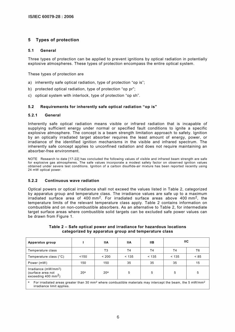
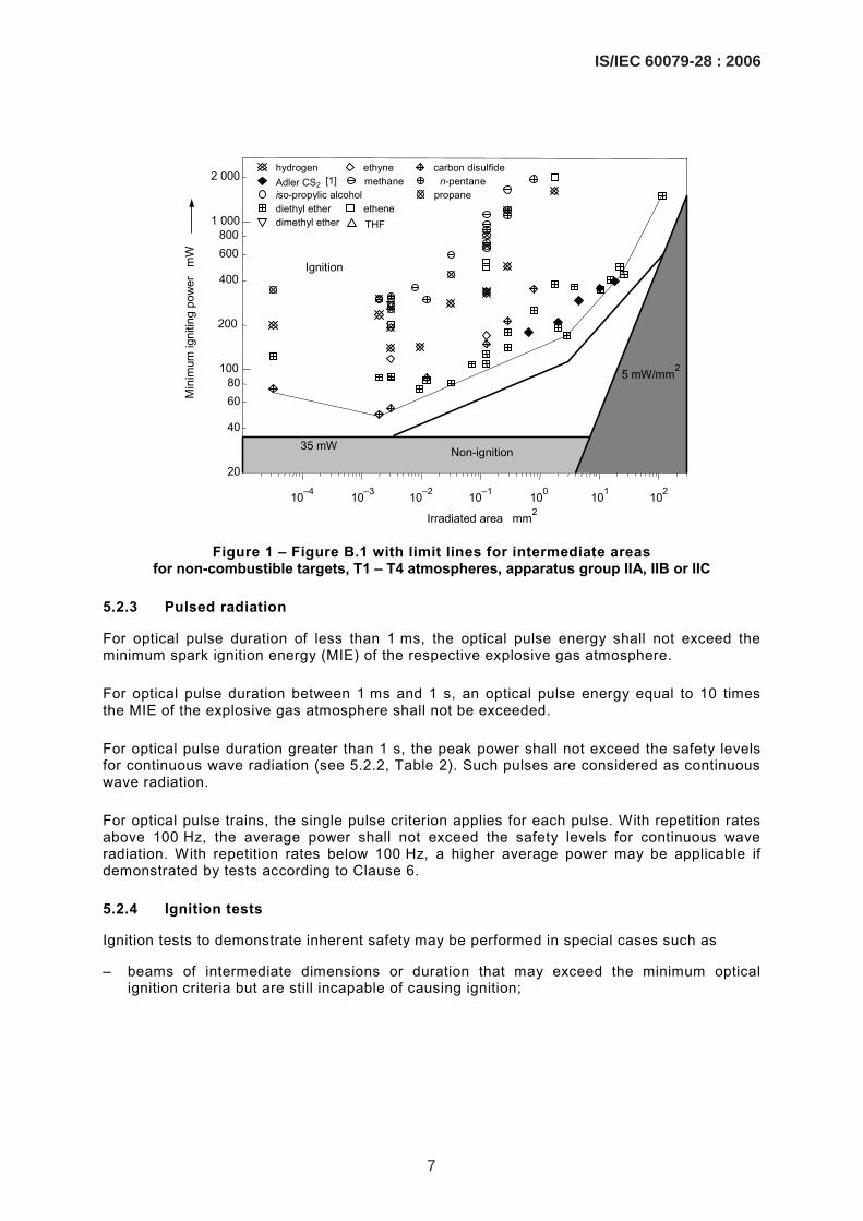
Optical powers or optical irradiance shall not exceed the values listed in Table 2, categorized by apparatus group and temperature class. The irradiance values are safe up to a maximum irradiated surface area of 400 mm2. For irradiated surface areas above 400 mm2, the temperature limits of the relevant temperature class apply. Table 2 contains information on combustible and on non-combustible absorbers. As an alternative to Table 2, for intermediate target surface areas where combustible solid targets can be excluded safe power values can be drawn from Figure 1.
Table 2 – Safe optical power and irradiance for hazardous locations categorized by apparatus group and temperature class
Apparatus group I IIA IIA IIB IIC
Temperature class T3 T4 T4 T4 T6
Temperature class (°C) <150 < 200 < 135 < 135 < 135 < 85
Power (mW) 150 150 35 35 35 15
Irradiance (mW/mm2) (surface area not exceeding 400 mm2)
20a 20a 5 5 5 5
a For irradiated areas greater than 30 mm2 where combustible materials may intercept the beam, the 5 mW/mm2 irradiance limit applies.
6
IS/IEC 60079-28 : 2006
10–4
20
40
60 80
100
200
400
600 800
1 000
2 000
Ignition
Non-ignition35 mW
hydrogen ethyne carbon disulfideAdler CS2 [1] methane n-pentaneiso-propylic alcohol propane diethyl ether ethene
THF dimethyl ether
Min
imum
igni
ting
pow
er
mW
Irradiated area mm2
10–3 10–2 10–1 100 101 102
5 mW/mm2
Figure 1 – Figure B.1 with limit lines for intermediate areas
for non-combustible targets, T1 – T4 atmospheres, apparatus group IIA, IIB or IIC
5.2.3 Pulsed radiation
For optical pulse duration of less than 1 ms, the optical pulse energy shall not exceed the minimum spark ignition energy (MIE) of the respective explosive gas atmosphere.
For optical pulse duration between 1 ms and 1 s, an optical pulse energy equal to 10 times the MIE of the explosive gas atmosphere shall not be exceeded.
For optical pulse duration greater than 1 s, the peak power shall not exceed the safety levels for continuous wave radiation (see 5.2.2, Table 2). Such pulses are considered as continuous wave radiation.
For optical pulse trains, the single pulse criterion applies for each pulse. With repetition rates above 100 Hz, the average power shall not exceed the safety levels for continuous wave radiation. With repetition rates below 100 Hz, a higher average power may be applicable if demonstrated by tests according to Clause 6.
5.2.4 Ignition tests
Ignition tests to demonstrate inherent safety may be performed in special cases such as
– beams of intermediate dimensions or duration that may exceed the minimum optical ignition criteria but are still incapable of causing ignition;
IS/IEC 60079-28 : 2006
7

– beams with complex time waveforms so that pulse energies and/or average power are not easily resolved;
– specific atmospheres, targets, or other specific applications that are demonstrably less severe than test conditions studied to date.
The test shall be done with 10 samples of the light source as specified in Clause 6. The test is passed if there is no ignition during the 10 tests.
5.2.5 Optical devices incorporating the inherently safe concept
Optical devices incorporating the inherently safe concept shall provide over-power/energy fault protection to prevent excessive beam strengths in potentially explosive atmospheres. The risk/hazard analysis shall determine when these additional devices are required. The failure modes of the optical source, the supply barrier, and the presence of an explosive atmosphere shall be considered during normal operation and during fault conditions to determine the requirement for additional protection.
Optical sources such as laser diodes or light-emitting diodes will fail if over-heated under over-power fault conditions. The thermal failure characteristic of certain optical sources may provide the necessary over-power fault protection (test of 10 samples).
Electrical circuits such as current and/or voltage limiters placed between the optical source and the electrical power source can provide over-power fault protection similar to intrinsically safe circuits.
Over-power fault protection shall be provided to the degree necessary for the intended EPL (see for example IEC 60079-11). For Ga equipment, for example, current and/or voltage limiters shall provide over-power fault protection after two countable faults are applied to the current and/or voltage limiter. For Gb equipment, the two-fault requirement can be reduced to one failure. For Gc equipmen,t the rated values shall be taken without assuming any fault. The thermal failure characteristic of certain low power optical sources such as light-emitting diodes is acceptable to provide adequate over-power protection for any EPL.
5.3 Requirements for protected optical radiation “op pr”
5.3.1 General
This concept requires radiation confined inside optical fibre or other transmission medium based on the assumption that there is no escape of radiation from the confinement. In this case, the performance of the confinement defines the safety level of the system.
The risk analysis provides the safety requirements based on postulated conditions (fault conditions or normal operation).
Optical fibre may be used for situations where there are no postulated conditions so that an external force may cause a break of the protective barrier. Additional protective means (e.g. robust cabling, conduit or raceway) shall be used when external forces may cause a break during normal or abnormal operations. The risk analysis will dictate the protective measures required to prevent a break and escape of radiation.
Where enclosures are used, they may allow an ignition source inside without igniting the atmosphere outside, provided they meet the requirements of the standard types of protection concerned (IEC 60079 series).
8
IS/IEC 60079-28 : 2006

5.3.2 Radiation inside fibre, etc. (no mechanical damage to be expected)
The optical fibre protects the release of optical radiation into the atmosphere during normal operating conditions. For foreseeable malfunctions, this can be provided by additional armouring, conduit, cable tray, or raceway.
5.3.3 Radiation inside enclosures
Incendive radiation inside enclosures is acceptable if the enclosure complies with recognised types of protection for electrical apparatus where an ignition source may be present inside (flameproof "d" enclosure, pressurised "p" enclosure, restricted breathing enclosure...) according to IEC 60079 series. It shall, however, be considered, that any radiation escaping from the enclosure has to be protected according to this standard.
5.4 Optical radiation interlock with optical fibre breakage “op sh”
This type of protection is applicable when the radiation is not inherently safe with interlock cut-off if the protection by the confinement fails and the radiation becomes unconfined on time scales suitably shorter than the ignition delay time.
The interlock cut-off shall be required to perform according to the requirements defined by the risk analysis. The methods given in appropriate standards (e.g. IEC 61508, IEC 61511) may be used to analyse equipment performance to have an availability or risk reduction factor, depending on the equipment protection level, as shown in Table 3.
Table 3 – Optical interlock availability or ignition risk reduction factor by EPL
EPL Safety availability Ignition risk reduction factor
Ga 0,999 to 0,9999 1 000 to 10 000
Gb 0,99 to 0,999 100 to 1 000
Gc 0,9 to 0,99 10 to 100
NOTE The values listed in Table 3 were derived from recommendations of the SAFEC report (Wilday 2000).
Where it can be demonstrated by the ignition hazard assessment (see Annex C), that the conditions for ignition are not attained readily after breakage of the fibre, shut down times used for eye protection purposes may be used (see IEC 60825-2:2000). This will typically be the case for Gc equipment, but may also apply for Gb equipment.
5.5 Suitability of types of protection
Where the ignition hazard assessment given in Annex C shows that ignitions due to optical radiation are to be expected, the following principles of using the types of protection can be applied.
IS/IEC 60079-28 : 2006
9

Table 4 – Application of types of protection for optic systems based on EPLs
Type(s) of protection Ga Gb Gc
Inherently safe optical radiation “op is” (see 5.2)
Safe with two faults
Safe with one fault
safe in normal operation
Yes
No
No
Yes
Yes
No
Yes
Yes
Yes
Protected fibre optic media with ignition capable beam “op pr” (see 5.3)
With additional mechanical protection
Without additional mechanical protection
No
No
Yes
No
Yes
Yes
Protected fibre optic media with ignition capable beam interlocked with fibre breakage “op sh” (see 5.4)
With additional mechanical protection
Without additional mechanical protection
Yes
No
Yes
Yes
Yes
Yes
None (unconfined, ignition capable beam) No No No
6 Type verifications and tests
6.1 Test set-up for ignition tests
6.1.1 Test vessel
Diameter >150 mm, height above ignition source >200 mm.
6.1.2 Energy and power measurements
Total uncertainty of energy and power measurement shall be less than 5 % relative, including variations of light source.
6.1.3 Ignition criterion
A temperature increase of at least 100 K, measured by a 0,5 mm diameter thermocouple bead, 100 mm above the hot spot , or the appearance of a flame.
6.1.4 Mixture temperature
40 °C or the maximum temperature of the specific application.
6.1.5 Mixture pressure
Ambient pressure according to IEC 60079-0.
6.1.6 Safety factor
A safety factor of 1,5 for cw radiation and 3 for pulsed radiation shall be applied to all results (as non-ignition results) obtained by the tests according to 6.3 or 6.4 before using these data as inherently safe data.
Where no ignition can be obtained during test (e.g. because the power or energy cannot be increased further more in the test), this factor shall also be applied to the highest non incendive beam strength data obtained.
10
IS/IEC 60079-28 : 2006

Another possibility to obtain safe beam strength data (including a safety factor) is to use a test gas that is more sensitive to ignition. For cw-equipment to be used in IIA/T3 atmospheres, this test gas can be ethene up to a size of the beam area of about 2 mm2.
NOTE As the ignition by a small hot surface is a process containing considerable statistical deviations, a safety factor is justified. Due to the same reason, great care is to be applied when judging experiments as non-incendive because small variations in test parameters may influence the results remarkably.
6.2 Reference test
6.2.1 Reference gas
Propane-air-mixture of 5 % or 4 % by volume, see Table A.1 (for ignition tests with continuous wave radiation and pulses above 1 s duration) respectively 4 % by volume (for pulsed radiation, single pulses below 1 ms duration), quiescent mixture.
6.2.2 Reference absorber
Absorption at investigated wavelength above 80 %, to be applied on the transmission fibre tip (fibre optics), or compressed respectively applied to an inert substrate (free beam transmission).
NOTE Experiments showed that for pulses in the micro and nanosecond range, a carbon black absorber gives lowest igniting pulse energies (absorption 99 %, combustible, high decomposition temperature) [17,20,22].
6.2.3 Reference test for continuous wave radiation and pulses above 1 s duration
The irradiated reference absorber has to be physically and chemically inert for the duration of the test. The absorber is needed to have very high absorption to nearly act as a black body. The set-up should be tested with the reference gas and absorber at 40 °C. For the testing of fibre optics, the absorber should be applied to the fibre tip in a very thin layer (~ 10 µm) (as a powder in suspension and dried afterwards). The reference values are given in Annex A (Table A.1). The test setup is acceptable if the achieved ignition values are not more than 20 % above the data from Table A.1. The absorber has to be undamaged at the end of the test.
For the testing of free beam transmission the smallest diameter of the beam should hit a plane layer of the target material applied to a substrate or compressed. The reference values are to be taken from Table A.1 for the respective beam diameter. The test setup is acceptable if the achieved ignition values are not more than 20 % above the data from Table A.1. The absorber has to be undamaged at the end of the test.
6.2.4 Reference test for pulsed radiation below 1 ms pulse duration
The irradiated reference absorber should be irradiated from the front (free beam irradiation) during all pulse tests. For the testing of free beam transmission the smallest diameter of the beam should hit a plane layer of the target material applied either to a substrate or is compressed to form a pellet. The reference value for a beam diameter of 90 µm is 499 µJ pulse energy for pulses of 90 ns and 600 µJ for pulses of 30 ns. The set-up should be tested with the reference gas and absorber at 40 °C. The test setup is acceptable if the achieved ignition values are not more than 20 % above the data from Table B.1.
NOTE Background information for the reference values are given in the literature [20].
IS/IEC 60079-28 : 2006
11
6.3 Test mixtures
6.3.1 Ignition tests with continuous wave radiation and pulses above 1 s duration
6.3.1.1 For T6/IIC atmospheres
CS2 in air, 1,5 % by volume, and diethyl ether, 12 % by volume.
If only diethyl ether is used, the minimum ignition powers or irradiances obtained have to be divided by a factor of 4 for further use.
6.3.1.2 For T4/IIA, T4/IIB and T4/IIC atmospheres
Diethyl ether, 12 % by volume.
6.3.1.3 For T3/IIA and I atmospheres
Propane in air, 5 % by volume.
6.3.1.4 For special applications
The atmosphere under consideration.
6.3.2 Ignition tests with single pulses below 1 ms duration
6.3.2.1 For IIC atmospheres
H2 in air, 12 % and 21 % by volume or CS2 in air, 6,5 % by volume.
6.3.2.2 For IIB atmospheres
Ethene in air, 5,5 % by volume.
6.3.2.3 For I and IIA atmospheres
Diethyl ether, 3,4 % by volume or propane in air, 4 % by volume; divide minimum ignition energies obtained with propane by 1.2 for further use.
6.3.2.4 For special applications
The atmosphere under consideration.
6.4 Tests for pulse trains and pulses between 1 ms and 1 s duration
Apply test configuration according to 6.3.1 and then test configuration according to 6.3.2, absorbers and mixtures as specified in 6.1 to 6.3.
7 Marking
7.1 General
The apparatus using optical radiation shall be additionally marked with the following.
12
IS/IEC 60079-28 : 2006

7.2 Marking information
The marking shall include
a) the symbol for the type of protection used: – “op is”: for inherently safe optical radiation, – “op pr”: for protected optical radiation, – “op sh”: for optical system with interlock;
b) the symbol of the group of the apparatus: – For the type of protection inherently safe optical radiation “op is”, the suffixes A, B or C
shall be used; – For apparatus not suitable for installation in a hazardous area, but providing optical
radiation, the marking for associated apparatus shall apply. If Table 2 requires a restriction of the temperature class, this shall be indicated following the type of protection. Example: [Ex op is T4 Gb] IIC;
c) equipment protection level Ga, Gb or Gc as determined by Table 4; d) a serial number, except for:
– connection accessories; optical fibre cables, etc., – very small apparatus on which there is limited space.
7.3 Examples of marking
− Apparatus which is complying with EPL Ga: Ex op is IIC T6 Ga
– Apparatus which is complying with EPL Gb: Ex op pr II T4 Gb
– Apparatus, which is installed outside the hazardous area and providing optical radiation to the hazardous area, limit values taken from Table 2:
[Ex op is T3 Ga] IIA
The certificate shall identify the relevant EPL of the equipment (there may be more than one EPL for the different parts of the equipment).
IS/IEC 60079-28 : 2006
13
Annex A (normative)
Reference test data
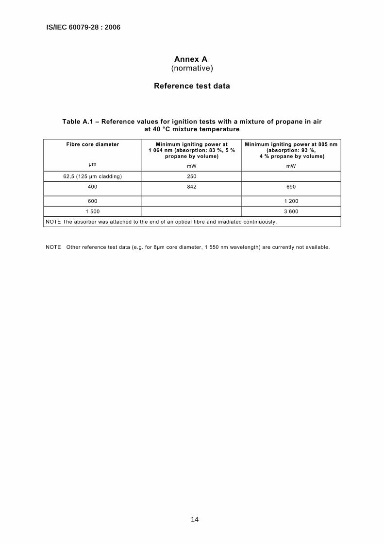
Table A.1 – Reference values for ignition tests with a mixture of propane in air at 40 °C mixture temperature
Fibre core diameter
µm
Minimum igniting power at 1 064 nm (absorption: 83 %, 5 %
propane by volume)
mW
Minimum igniting power at 805 nm (absorption: 93 %,
4 % propane by volume)
mW
62,5 (125 µm cladding) 250
400 842 690
600 1 200
1 500 3 600
NOTE The absorber was attached to the end of an optical fibre and irradiated continuously.
NOTE Other reference test data (e.g. for 8µm core diameter, 1 550 nm wavelength) are currently not available.
14
IS/IEC 60079-28 : 2006

Annex B (informative)
Ignition mechanisms 3
The potential hazard associated with optics in the infrared and visible electromagnetic spectrum depends on
• laser wavelength (absorption properties),
• absorber material (inert, reactive),
• fuel,
• pressure,
• irradiated area,
• irradiation time.
There is an immense number of combinations of these factors that will influence the hazard of optics in explosive atmosphere and at least the ignition mechanism. Worst case conditions arise when an absorber is present. When the dimensions of the radiation and or the absorber fall below the quenching distance of the explosive gas, the ignition can be seen as point ignition. However, radiation from the end of a fibre optic cable diverges rapidly and the irradiated area may reach dimensions of square centimetres. The conditions for ignition can be characterised in terms of the fundamental parameters energy, area and time.
Area tends to Time tends to Ignition criterion
(1) zero infinity minimum power
(2) infinity infinity minimum irradiance
(3) zero zero minimum energy
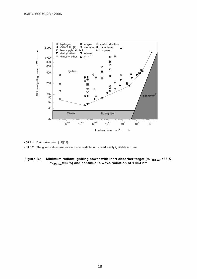
(4) infinity zero radiant exposure Infinite time means continuous wave radiation. The research results for small and big areas are given in Table B.1, Figure B.1 and Figure B.2. In both regimes, ignition takes place via hot surface ignition when the beam hits an absorber. The smaller the surface, the higher the igniting irradiance. This means that a smaller surface has to be heated to higher temperatures to cause an ignition. No ignition was observed below 50 mW optical power for all gas/vapour mixture (excluding carbon disulfide). This supports the maximum permissible power value of 35 mW including a safety margin, which also has to consider the non-ideal grey body absorption of the inert absorber. Experiments with reactive absorbers (coal, carbon black and a toner) showed, that even though they have higher absorption, they were less effective as ignition sources. The n-alkanes do not ignite below 200 mW (150 mW including safety margin). For bigger irradiated areas, a permissible value of 5 mW/mm2 is much more realistic than a restrictive power criterion.
————————— 3 The information provided in this annex is taken from reference [17] of Bibliography.
IS/IEC 60079-28 : 2006
15

In the small area short time regime, a laser pulse can create an ignition source similar to an electric spark by a breakdown in air. It is known from the literature [26] that such spark with an energy approaching the electrical minimum ignition energy (MIE) is able to ignite an explosive mixture under optimised conditions (µs and ns pulses).
The effectiveness of this ignition process depends on
– pulse length and repetition rate, – wavelength, – target (absorber) material, – irradiance and radiant exposure.
Microsecond pulses and nanosecond pulses with energies close to the MIE were found to ignite explosive mixtures as shown in Table B.2. In this case, the combustible carbon black target is the most effective absorber. The properties of carbon black support this breakdown in comparison to the inert material chosen in the continuous wave experiments (very high absorption, high decomposition temperature, electron-rich structure and combustibility). For pulses in the millisecond range without a breakdown process but heating of the target, ignition energies are more than one order of magnitude higher than the electrical MIE. Here, the inert grey body is the ideal absorber. Pulses longer than 1 s should be treated as continuous wave radiation.
For pulse trains, the ignition criterion for each individual pulse is the energy criterion given above when the pulse is shorter then 1 s. With higher repetition rates, the previous pulse might have an influence on the behaviour of the irradiated area with the actual pulse. For repetition rates greater than 100 Hz, the average power should be restricted to the continuous wave limit. This limitation forces a maximum repetition rate for a defined pulse energy. The shorter the pulse, the higher the permissible peak power but the longer the duty cycle. This gives time for cooling of the target or decay of a spark or plume of hot material. Experiments showed [20] that for nanosecond pulses in the range of the MIE (up to 400 µJ), a spark lifetime of more than 100 µs is not to be expected for a beam diameter of 90 µm. For long pulse duration >1 s, the peak power should be restricted to the corresponding cw-limit.
The remaining combination of fundamental parameters, i.e. short times over infinite area, can be evaluated by the results for the other regimes.
16
IS/IEC 60079-28 : 2006
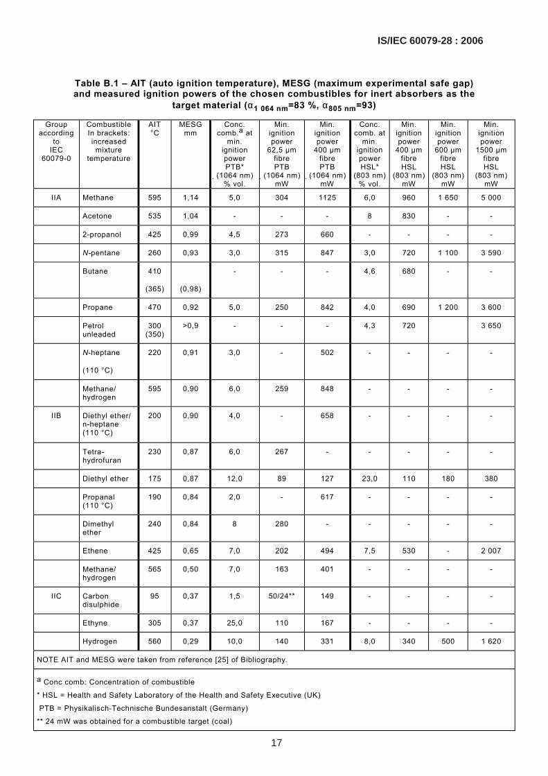
Table B.1 – AIT (auto ignition temperature), MESG (maximum experimental safe gap) and measured ignition powers of the chosen combustibles for inert absorbers as the
target material (α1 064 nm=83 %, α805 nm=93)
Group according
to IEC
60079-0
Combustible In brackets: increased
mixture temperature
AIT °C
MESG mm
Conc. comb.a at
min. ignition power PTB*
(1064 nm) % vol.
Min. ignition power
62,5 µm fibre PTB
(1064 nm)mW
Min. ignition power
400 µm fibre PTB
(1064 nm)mW
Conc. comb. at
min. ignition power HSL*
(803 nm)% vol.
Min. ignition power
400 µm fibre HSL
(803 nm) mW
Min. ignition power
600 µm fibre HSL
(803 nm)mW
Min. ignition power
1500 µm fibre HSL
(803 nm) mW
IIA Methane 595 1,14 5,0 304 1125 6,0 960 1 650 5 000
Acetone 535 1,04 - - - 8 830 - -
2-propanol 425 0,99 4,5 273 660 - - - -
N-pentane 260 0,93 3,0 315 847 3,0 720 1 100 3 590
Butane 410
(365)
(0,98)
- - - 4,6 680 - -
Propane 470 0,92 5,0 250 842 4,0 690 1 200 3 600
Petrol unleaded
300 (350)
>0,9 - - - 4,3 720 3 650
N-heptane
(110 °C)
220 0,91 3,0 - 502 - - - -
Methane/ hydrogen
595 0,90 6,0 259 848 - - - -
IIB Diethyl ether/ n-heptane (110 °C)
200 0,90 4,0 - 658
- - - -
Tetra-hydrofuran
230 0,87 6,0 267 - - - - -
Diethyl ether 175 0,87 12,0 89 127 23,0 110 180 380
Propanal (110 °C)
190 0,84 2,0 - 617 - - - -
Dimethyl ether
240 0,84 8 280 - - - - -
Ethene 425 0,65 7,0 202 494 7,5 530 - 2 007
Methane/ hydrogen
565 0,50 7,0 163 401 - - - -
IIC Carbon disulphide
95 0,37 1,5 50/24** 149 - - - -
Ethyne 305 0,37 25,0 110 167 - - - -
Hydrogen 560 0,29 10,0 140 331 8,0 340 500 1 620
NOTE AIT and MESG were taken from reference [25] of Bibliography.
a Conc comb: Concentration of combustible
* HSL = Health and Safety Laboratory of the Health and Safety Executive (UK)
PTB = Physikalisch-Technische Bundesanstalt (Germany)
** 24 mW was obtained for a combustible target (coal)
IS/IEC 60079-28 : 2006
17
20
40
60 80
100
200
400
600 800
1 000
2 000 hydrogen ethyne carbon disulfideAdler CS2 [7] methane n-pentaneiso-propylic alcohol propane diethyl ether ethene
THF dimethyl ether
Min
imum
igni
ting
pow
er
mW
10–4
Ignition
Non-ignition35 mW
Irradiated area mm2
10–3 10–2 10–1 100 101
5 mW/mm2
102
NOTE 1 Data taken from [17][23].
NOTE 2 The given values are for each combustible in its most easily ignitable mixture.
Figure B.1 – Minimum radiant igniting power with inert absorber target (α1 064 nm=83 %, α805 nm=93 %) and continuous wave-radiation of 1 064 nm
18
IS/IEC 60079-28 : 2006

10–5
200
400
600
800
1 000
2 000
4 000
6 000
methane HSL PTB Dubaniewicz [8] propane HSL PTB n-butane HSL n-pentane HSL PTB
Min
imum
igni
ting
pow
er
mW
Irradiated area mm210–4 10–3 10–2 10–1 100
Figure B.2 – Minimum radiant igniting power with inert absorber target
(α1 064 nm=83 %, α805 nm=93 %) and continuous wave-radiation (PTB: 1 064 nm, HSL: 805 nm, [24]: 803 nm) for some n-alkanes
IS/IEC 60079-28 : 2006
19

Table B.2 – Comparison of measured minimum igniting optical pulse energy (Qe,pi,min)
at 90 µm beam diameter with auto ignition temperatures (AIT) and minimum ignition energies (MIE) from literature [25] at concentrations in percent by volume (ϕ)
Fuel Qe,p
i,min
µJ
ϕ
%
AIT
°C
MIE
µJ
ϕMIE
%
Qe,pi,min
/MIE
70 µs spiked pulse
N-Pentane 669 3 260 280 3,3 2,4
>55 000 6,4
Propane 784 5,5 470 240 5,2 3,3
Diethyl ether 661 3,4 175 190 5,2 3,5
1 285 5,2 6,8
Ethene 218 5,5 425 82 6,5 2,7
Hydrogen 88 21 560 17 28 5,2
Carbon disulfide 79 6,5 95 9 8,5 9,3
Nanosecond pulses (20 ns to 200 ns)
Propane 499 4,0 470 240 5,2 2,1
Ethene 179 5,5 425 82 6,5 2,2
Hydrogen 44 12 560 17 28 2,6
46 21 2,7
NOTE The target material was carbon black.
20
IS/IEC 60079-28 : 2006

Annex C (normative)
Ignition hazard assessment
An explosive combustible air atmosphere can be ignited by optical radiation provided that the beam strength exceeds an inherently safe level and an absorbing solid exists in the beam that can cause a hot spot and an ignition source accordingly, or the conditions for a breakdown apply (threshold irradiance exceeded). See Figure C.1.
Radiation source present
Absorber present
Explosive atmosphere
present
and
or
Fibre breakageSurface Particle Open beam Zone 0
Zone 1 Zone 2
Explosion
or or
Figure C.1 – Ignition hazard assessment
If these conditions apply, the types of protection b) and c) given in 5.1 shall be used.
Where these conditions do not apply, an ignition hazard may not exist. A further assessment considering all conditions necessary for ignition
– for the specific case or equipment, – and considering the requirements for the different EPLs according to 4.2
shall be performed and measures necessary derived accordingly.
NOTE 1 Although not covered by this standard, all possible ways to ignite an explosive mixture by optical radiation (see Introduction and this Annex C) must be checked before excluding this ignition source.
It is important to understand that even in the case of open radiation, exceeding the inherently safe level does not readily lead to ignition, as additional provisions (different from the electrical spark ignition) are necessary to start an ignition process.
IS/IEC 60079-28 : 2006
21

NOTE 2 As an example, a gas analysis system where in the beam there is no absorbing target that can be heated up to be an ignition source may not create an ignition hazard with respect to the optical radiation. In this specific case, there will be absorption of optical energy in the mixture itself, but it can be easily demonstrated in most cases that there is no heating of the mixture to such an extent that it will be ignited.
This assessment applies also to the use of the protections concepts themselves. Where an enclosure for the beam is used that does not allow solid materials to enter it (although it allows the explosive atmosphere to enter), an ignition source is prevented inside this enclosure, provided there exists no other target inside.
If a fibre breakage is assumed, where the concept of interlock with the breakage detection is used, it may be safe to use the shut down times allowed for eye protection (IEC 60825-2: 2000), if it is improbable that the beam will hit a target with an incendive intensity.
22
IS/IEC 60079-28 : 2006
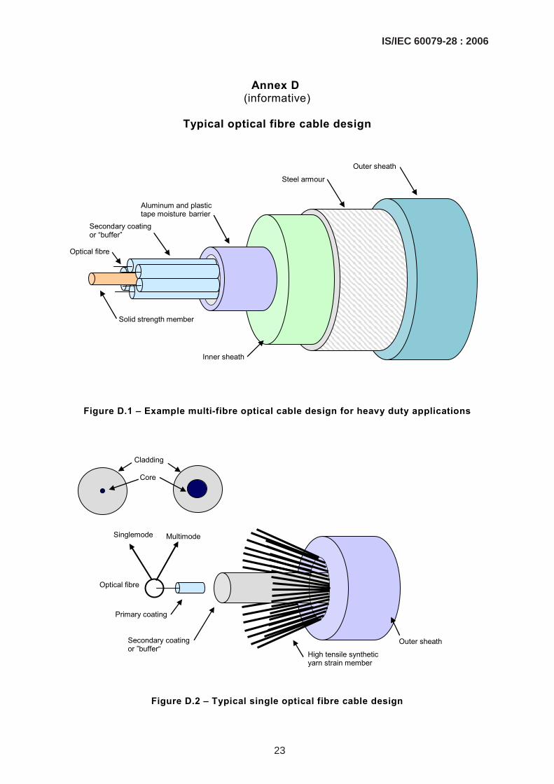
Annex D (informative)
Typical optical fibre cable design
Solid strength member
Secondary coating or “buffer”
Aluminum and plastic tape moisture barrier
Inner sheath
Steel armour
Outer sheath
Optical fibre
Figure D.1 – Example multi-fibre optical cable design for heavy duty applications
Optical fibre
High tensile synthetic yarn strain member
Outer sheath Secondary coating or ”buffer“
Singlemode Multimode
Core
Cladding
Primary coating
Figure D.2 – Typical single optical fibre cable design
IS/IEC 60079-28 : 2006
23

Annex E (informative)
Introduction of an alternative risk assessment method
encompassing “equipment protection levels” for Ex equipment
E.0 Introduction
This annex provides an explanation of the concept of a risk assessment method encompassing equipment protection levels (EPLs). These EPLs are introduced to enable an alternative approach to current methods of selecting Ex equipment.
E.1 Historical background
Historically, it has been acknowledged that not all types of protection provide the same level of assurance against the possibility of an incendive condition occurring. The installation standard IEC 60079-14 [8] allocates specific types of protection to specific zones, on the statistical basis that the more likely or frequent the occurrence of an explosive atmosphere, the greater the level of security required against the possibility of an ignition source being active.
Hazardous areas (with the normal exception of coal mining) are divided into zones, according to the degree of hazard. The degree of hazard is defined according to the probability of the occurrence of explosive atmospheres. Generally, no account is taken of the potential consequences of an explosion, nor of other factors such as the toxicity of materials. A true risk assessment would consider all factors.
Acceptance of equipment into each zone is historically based on the type protection. In some cases, the type of protection may be divided into different levels of protection which again historically correlate to zones. For example, intrinsic safety is divided into levels of protection ia and ib. The encapsulation “m” standard includes two levels of protection “ma” and “mb”.
In the past, the equipment selection standard has provided a solid link between the type of protection for the equipment and the zone in which the equipment can be used. As noted earlier, nowhere in the IEC system of explosion protection is there any account taken of the potential consequences of an explosion, should it occur.
However, plant operators often make intuitive decisions on extending (or restricting) their zones in order to compensate for this omission. A typical example is the installation of "zone 1 Type" navigation equipment in zone 2 areas of offshore oil production platforms, so that the navigation equipment can remain functional even in the presence of a totally unexpected prolonged gas release. In the other direction, it is reasonable for the owner of a remote, well secured, small pumping station to drive the pump with a "zone 2 Type" motor, even in zone 1, if the total amount of gas available to explode is small and the risk to life and property from such an explosion can be discounted.
The situation became more complex with the publication of the first edition of IEC 60079-26 which introduced additional requirements to be applied for equipment intended to be used in zone 0. Prior to this, Ex ia was considered to be the only technique acceptable in zone 0.
It has been recognized that it is beneficial to identify and mark all products according to their inherent ignition risk. This would make equipment selection easier and provide the ability to better apply a risk assessment approach, where appropriate.
24
IS/IEC 60079-28 : 2006

E.2 General
A risk assessment approach for the acceptance of Ex equipment has been introduced as an alternative method to the current prescriptive and relatively inflexible approach linking equipment to zones. To facilitate this, a system of equipment protection levels has been introduced to clearly indicate the inherent ignition risk of equipment, no matter what type of protection is used.
The system of designating these equipment protection levels is as follows.
E.2.1 Coal mining (group I)
E.2.1.1 EPL Ma
Equipment for installation in a coalmine, having a "very high" level of protection, which has sufficient security that it is unlikely to become an ignition source, even when left energised in the presence of an outbreak of gas.
NOTE Typically, communications circuits and gas detection equipment will be constructed to meet the Ma requirements – for example an Ex ia telephone circuit.
E.2.1.2 EPL Mb
Equipment for installation in a coal mine, having a "high" level of protection, which has sufficient security that it is unlikely to become a source of ignition in the time span between there being an outbreak of gas and the equipment being de-energised.
NOTE Typically, all the coal winning equipment will be constructed to meet the Mb requirements – for example Ex d motors and switchgear.
E.2.2 Gases (group II)
E.2.2.1 EPL Ga
Equipment for explosive gas atmospheres, having a "very high" level of protection, which is not a source of ignition in normal operation, expected faults or when subject to rare faults.
E.2.2.2 EPL Gb
Equipment for explosive gas atmospheres, having a "high" level of protection, which is not a source of ignition in normal operation or when subject to faults that may be expected, though not necessarily on a regular basis.
NOTE The majority of the standard protection concepts bring equipment within this equipment protection level.
E.2.2.3 EPL Gc
Equipment for explosive gas atmospheres, having an "enhanced" level of protection, which is not a source of ignition in normal operation and which may have some additional protection to ensure that it remains inactive as an ignition source in the case of regular expected occurrences (for example failure of a lamp).
NOTE Typically, this will be Ex n equipment.
IS/IEC 60079-28 : 2006
25

E.2.3 Dusts (group III)
E.2.3.1 EPL Da
Equipment for combustible dust atmospheres, having a "very high" level of protection, which is not a source of ignition in normal operation or when subject to rare faults.
E.2.3.2 EPL Db
Equipment for combustible dust atmospheres, having a "high" level of protection, which is not a source of ignition in normal operation or when subject to faults that may be expected, though not necessarily on a regular basis.
E.2.3.3 EPL Dc
Equipment for combustible dust atmospheres, having an "enhanced" level of protection, which is not a source of ignition in normal operation and which may have some additional protection to ensure that it remains inactive as an ignition source in the case of regular expected occurrences.
For the majority of situations, with typical potential consequences from a resultant explosion, it is intended that the following would apply for use of the equipment in zones. (This is not directly applicable for coal mining, as the zone concept does not generally apply.) See Table E.1.
Table E.1 – Traditional relationship of EPLs to zones (no additional risk assessment)
Equipment protection level Zone
Ga 0
Gb 1
Gc 2
Da 20
Db 21
Dc 22
E.3 Risk of ignition protection afforded
The various levels of protection of equipment must be capable of functioning in conformity with the operational parameters established by the manufacturer to that level of protection.
26
IS/IEC 60079-28 : 2006

Table E.2 – Description of risk of ignition protection provided
Equipment protection level Protection afforded Group
Performance of protection
Conditions of operation
Ma Very High
Group I
Two independent means of protection or safe even when two faults occur independently of each other
Equipment remains functioning when explosive atmosphere present
Ga Very High
Group II
Two independent means of protection or safe even when two faults occur independently of each other
Equipment remains functioning in zones 0,1 and 2
Da Very High
Group III
Two independent means of protection or safe even when two faults occur independently of each other
Equipment remains functioning in zones 20, 21 and 22
Mb High
Group I
Suitable for normal operation and severe operating conditions
Equipment de-energised when explosive atmosphere present
Gb High
Group II
Suitable for normal operation and frequently occurring disturbances or equipment where faults are normally taken into account
Equipment remains functioning in zones 1 and 2
Db High
Group III
Suitable for normal operation and frequently occurring disturbances or equipment where faults are normally taken into account
Equipment remains functioning in zones 21 and 22
Gc Enhanced
Group II
Suitable for normal operation
Equipment remains functioning in zone 2
Dc Enhanced
Group III
Suitable for normal operation
Equipment remains functioning in zone 22
E.4 Implementation
The 4th edition of IEC 60079-14 (encompassing the former requirements of IEC 61241-14) will introduce the EPLs to allow a system of “risk assessment" as an alternative method for the selection of equipment (see Table E.2). Reference will also be included in the classification standards IEC 60079-10 and IEC 61241-10 [14].
The additional marking and the correlation of the existing types of protection are being introduced into the revisions to the following IEC standards [3-7], [9-11]:
• IEC 60079-0 (encompassing the former requirements of IEC 61241-0 [12])
• IEC 60079-1
• IEC 60079-2 (encompassing the former requirements of IEC 61241-4 [13])
IS/IEC 60079-28 : 2006
27

• IEC 60079-5
• IEC 60079-6
• IEC 60079-7
• IEC 60079-11 (encompassing the former requirements of IEC 61241-11 [15])
• IEC 60079-15
• IEC 60079-18 (encompassing the former requirements of IEC 61241-18 [16])
• IEC 60079-26
• IEC 60079-28
For the types of protection for explosive gas atmospheres the EPLs require additional marking. For explosive dust atmospheres, the present system of marking the zones on equipment is being replaced by marking the EPLs.
28
IS/IEC 60079-28 : 2006
Bibliography
[1] IEC 60050-426:1990, International Electrotechnical Vocabulary (IEV) – Chapter 426: Electrical apparatus for explosive atmospheres
[2] IEC 60050-731:1991, International Electrotechnical Vocabulary (IEV) – Chapter 731: Optical fibre communication
[3] IEC 60079-1, Electrical apparatus for explosive gas atmospheres – Part 1: Flameproof enclosures "d"
[4] IEC 60079-2, Electrical apparatus for explosive gas atmospheres – Part 2: Pressurized enclosures "p"
[5] IEC 60079-5, Electrical apparatus for explosive gas atmospheres – Part 5: Powder filling “q”
[6] IEC 60079-6, Electrical apparatus for explosive gas atmospheres – Part 6: Oil immersion “o”
[7] IEC 60079-7, Explosive atmospheres – Part 7: Equipment protection by increased safety “e”
[8] IEC 60079-14, Electrical apparatus for explosive gas atmospheres – Part 14: Electrical installations in hazardous areas (other than mines)
[9] IEC 60079-15, Electrical apparatus for explosive gas atmospheres – Part 15: Construction, test and marking of type of protection "n" electrical apparatus
[10] IEC 60079-18, Explosive atmospheres – Part 18: Electrical equipment – Requirements for encapsulation "m"
[11] IEC 60079-26:2004, Electrical apparatus for explosive gas atmospheres – Part 26: Construction, test and marking of Group II Zone 0 electrical apparatus
[12] IEC 61241-0, Electrical apparatus for use in the presence of combustible dust – Part 0: General requirements
[13] IEC 61241-4, Electrical apparatus for use in the presence of combustible dust – Part 4: Type of protection "pD"
[14] IEC 61241-10, Electrical apparatus for use in the presence of combustible dust – Part 10: Classification of areas where combustible dusts are or may be present
[15] IEC 61241-11, Electrical apparatus for use in the presence of combustible dust – Part 11: Protection by intrinsic safety 'iD'
[16] IEC 61241-18, Electrical apparatus for use in the presence of combustible dust – Part 18: Protection by encapsulation 'mD'
IS/IEC 60079-28 : 2006
29

[17] CARLETON, F.B., BOTHE, H., PROUST, C., and HAWKSWORTH, S., Prenormative Research on the Use of Optics in Potentially Explosive Atmospheres, European Commission Report EUR 19617 EN, 2000
[18] McGEEHIN, P., Optical Techniques in Industrial Measurements: Safety in Hazardous Environments, European Commission Report EC 16011 EN, 1995
[19] WELZEL, M.M., Entzündung von explosionsfähigen Dampf/Luft- und Gas/Luft- Gemischen durch kontinuierliche optische Strahlung, PTB-Report W-67, ISBN 3-89429-812-X , 1996
[20] SCHENK, S., Entzündung explosionsfähiger Atmosphäre durch gepulste optische Strahlung, PTB-Report Th-Ex 17, ISBN 3-89701-667-2, 2001
[21] WELZEL, M.M., SCHENK, S., HAU, M., CAMMENGA, H.K., and BOTHE, H., J. Hazard. Mater. A72:1 (2000)
[22] SCHENK, S., BOTHE, H., and CAMMENGA, H.K., in BRADLEY, D., Proc. Third International Seminar on Fire and Explosions Hazards 2000, 2001, p. 495
[23] ADLER, J., CARLETON, F.B. and WEINBERG, F.J., Proc. R. Soc. Lond. A (1993) 440, 443-460
[24] DUBANIEWICZ, T.H., CASHDOLLAR, K.L., GREEN, G.M. and CHAIKEN, R.F., J. Loss Prevent. Proc. 13: 349-359 (2000)
[25] DECHEMA, PTB, BAM: ChemSafe: Sicherheitstechnische Datenbank, Karlsruhe. STN Datenbank, 1995
[26] SYAGE, J.A., FOURNIER, E.W., RIANDA, R. and COHEN, R.B., J. Appl. Phys. 64:1499
[27] WILDAY, A.J., WRAY, A.M., EICKHOFF, F., UNRUH, M., HALAMA, S., FAE, E., CONDE LAZARO, E., REINA PERBAL, P
[28] Determination of Safety Categories of Electrical Devices Used in Potentially Explosive Atmospheres (SAFEC) Contract SMT4-CT98-2255, http://www.prosicht.com/EC-Projects/SAFEC/finalrp4.pdf (Safetynet, Prosicht, Germany, 2000).
[29] ANSI/ISA-TR12.21.01-2004, Use of Fiber Optic Systems in Class I Hazardous (Classified) Locations. ISA, Research Triangle Park, North Carolina, USA, 2004.
___________
30
IS/IEC 60079-28 : 2006

Only the English language text of the International Standard has been retained while adopting it inthis Indian Standard, and as such the page numbers given here are not the same as in the IECPublication.
For the purpose of deciding whether a particular requirement of this standard is complied with, thefinal value, observed or calculated, expressing the result of a test, shall be rounded off in accordancewith IS 2 : 1960 ‘Rules for rounding off numerical values (revised)’. The number of significant placesretained in the rounded off value should be the same as that of the specified value in this standard.
(Continued from second cover)

Bureau of Indian Standards
BIS is a statutory institution established under the Bureau of Indian Standards Act, 1986 to promoteharmonious development of the activities of standardization, marking and quality certification of goodsand attending to connected matters in the country.
Copyright
BIS has the copyright of all its publications. No part of these publications may be reproduced in any formwithout the prior permission in writing of BIS. This does not preclude the free use, in course of imple-menting the standard, of necessary details, such as symbols and sizes, type or grade designations.Enquiries relating to copyright be addressed to the Director (Publications), BIS.
Review of Indian Standards
Amendments are issued to standards as the need arises on the basis of comments. Standards are alsoreviewed periodically; a standard along with amendments is reaffirmed when such review indicates thatno changes are needed; if the review indicates that changes are needed, it is taken up for revision. Usersof Indian Standards should ascertain that they are in possession of the latest amendments or edition byreferring to the latest issue of ‘BIS Catalogue’ and ‘Standards: Monthly Additions’.
This Indian Standard has been developed from Doc No.: ETD 22 (6265).
Amendments Issued Since Publication______________________________________________________________________________________
Amendment No. Date of Issue Text Affected______________________________________________________________________________________
______________________________________________________________________________________
______________________________________________________________________________________
______________________________________________________________________________________
______________________________________________________________________________________
BUREAU OF INDIAN STANDARDSHeadquarters:
Manak Bhavan, 9 Bahadur Shah Zafar Marg, New Delhi 110002Telephones: 2323 0131, 2323 3375, 2323 9402 Website: www.bis.org.in
Regional Offices: Telephones
Central : Manak Bhavan, 9 Bahadur Shah Zafar Marg 2323 7617NEW DELHI 110002 2323 3841
Eastern : 1/14, C.I.T. Scheme VII M, V.I.P. Road, Kankurgachi 2337 8499, 2337 8561KOLKATA 700054 2337 8626, 2337 9120
Northern : SCO 335-336, Sector 34-A, CHANDIGARH 160022 260 3843260 9285
Southern : C.I.T. Campus, IV Cross Road, CHENNAI 600113 2254 1216, 2254 14422254 2519, 2254 2315
Western : Manakalaya, E9 MIDC, Marol, Andheri (East) 2832 9295, 2832 7858MUMBAI 400093 2832 7891, 2832 7892
Branches: AHMEDABAD. BANGALORE. BHOPAL. BHUBANESHWAR. COIMBATORE. DEHRADUN.FARIDABAD. GHAZIABAD. GUWAHATI. HYDERABAD. JAIPUR. KANPUR. LUCKNOW.NAGPUR. PARWANOO. PATNA. PUNE. RAJKOT. THIRUVANATHAPURAM. VISAKHAPATNAM.
Published by BIS, New Delhi
{
{{
{{