Embed Size (px)
Citation preview

D11193 Rev F 4/13/16

2
Contents
CONTENTS ....................................................................... 2
INTRODUCTION ............................................................. 3 SUSPENSION RATING ........................................................ 3 SERIAL NUMBER TAG INFORMATION ................................ 3 VEHICLE TOWING AND JACKING INFORMATION ............... 3
SYSTEM OPERATION .................................................... 4 System Start Up: .......................................................... 4 ON/OFF Button: .......................................................... 4 Warning Light: ............................................................. 4 Ride Mode Adjustment: ................................................ 4 Ride Height Adjustment: .............................................. 4 Depressurizing the System ........................................... 5 Calibrating the System ................................................. 6 Calibrating the Steering Sensor Only .......................... 6 Bleeding the System ..................................................... 7 Checking Fluid Level ................................................... 7 Checking Fittings for Leaks ......................................... 8
SERVICE INTERVALS ................................................... 8 Once Daily or Before Each Shift of Usage .................. 8 Initial 1,000 mile (1,600 km) Inspection ...................... 8 Routine Maintenance 25,000 miles (40,000 km) or 6
month maximum Interval ............................................. 8
MAINTENANCE RECORD ............................................. 9
TROUBLESHOOTING .................................................. 10 Issues with Vehicle Raising/Pump ............................. 10 Issues with Vehicle Lowering/Dump Valve ................ 10 Issues with One Corner Not Leveling Properly ......... 11 Issues with Height Sensors ......................................... 11 Issues with Ride/Handling ......................................... 11 Issues with Steering Sensor ........................................ 11 Issues with Vehicle Speed Signal ............................... 12 Issues with Vehicle Brake Signal ............................... 12 Issues with Door Switch ............................................. 12 Issues with Vehicle Ignition Signal ............................ 12 Issues with Vehicle Park Signal ................................. 12 Issues with Driver Interface ....................................... 12 Issues with Power Module ......................................... 13 Issues with Strut Assembly ......................................... 13 Issues with Secondary Volume Assembly ................... 14
ABBREVIATIONS ............................................................. 14
PART IDENTIFICATION: ............................................ 15 DS137FS2 .................................................................. 15 Bill of Materials ......................................................... 16 DS147FS2 .................................................................. 17 Bill of Materials ......................................................... 18 Front Hangers ............................................................ 19 Upper Strut Mounts.................................................... 20 Axle Clamp Hangers .................................................. 21 Control Arms .............................................................. 22 Bridge ........................................................................ 23 Track Rod and Tie Plate ............................................ 23 Strut Assembly Installation ........................................ 24 Jounce Bumpers ......................................................... 25
Height Sensors ............................................................ 25 Power Module Installation ......................................... 26 Secondary Volumes (DS137FS2) ................................ 27 Secondary Volumes (DS147FS2) ................................ 28 Steering Sensor Installation ........................................ 29
ELECTRICAL SCHEMATICS ...................................... 30
APPENDIX A: PART NUMBER COMPATIBILITY –
SERIAL NUMBER CUTOFF ......................................... 33

3
Introduction
This manual provides installation information for the
LiquidSpring CLASS® DS137FS2 and DS147FS2 series of
rear axle suspension systems for the Ford F450/F550
SuperDuty Cab Chassis.
Before you begin installation of the suspension system:
1. Read and understand all instructions and procedures
prior to installation of components.
2. Read and observe all Warning and Caution hazard
alert messages in this publication. They provide
information that can help prevent serious personal
injury, damage to components, or both.
3. Follow your company’s maintenance and service,
installation, and diagnostics guidelines.
4. Use special tools when required to help avoid serious
personal injury and damage to components.
Throughout this manual, important product information is
indicated. These terms are defined as follows:
NOTE: Includes additional information to enable accurate
and easy performance of procedures.
IMPORTANT: Includes additional information that if not
followed could lead to hindered product performance
and/or product failure.
CAUTION: A caution indicates procedures that must be
followed exactly. Damage to equipment or suspension
components and personal injury can occur if the procedure is
not followed.
WARNING: A warning indicates procedures that must be
followed exactly. Serious personal injury can occur if the
procedure is not followed.
These instructions cover the following models:
Model Application
DS137FS2 12,00 GAWR F450
DS137FS2 13,660 GAWR F550
DS147FS2 14,706 GAWR F550
LiquidSpring LLC reserves the right to modify the suspension
and/or procedures and to change specifications at any time
without notice and without incurring obligation.
Suspension Rating
Model Suspension Rating
DS137FS2 (on F450) 12,000 lbs
DS137FS2 (on F550 13,660 lbs
DS147FS2 14,706 lbs
WARNING: Overloading suspension system may result in
abnormal handling characteristics and premature wear of
components.
Serial Number Tag Information
The suspension model, serial number, and maximum axle
capacity are found on an aluminum tag that is riveted to the
Left Hand Suspension Hanger as shown in Figure 2. This
information will aid you when contacting the chassis
manufacturer or LiquidSpring LLC.
Figure 1. Suspension Identification
Figure 2. Serial Number Tag Location
Vehicle Towing and Jacking Information
Before attempting any type of towing procedures, contact the
OEM/Coach Builder for instructions.
NOTE: Before towing vehicle, check with local authorities,
such as Department of Transportation, for permissible towing
methods. Some states do not permit towing vehicles by chains
or towing straps.
Do not attach tow apparatus (hooks, chains, straps, etc.) to the
suspension components.
WARNING: Attaching towing equipment to improper
locations and failure to utilize OEM/Coach Builder
recommended towing methods could result in one or more
of the following:
Damage to the suspension and/or vehicle,
Loss of vehicle control,
Possible disconnect from the vehicle.
WARNING: Do not apply jack to bottom of front hanger
or other suspension components. Appling a jack to
improper locations can result in damage to the suspension
and/or vehicle and severe personal injury.

4
System Operation
System Start Up:
In most instances, the suspension system can be left
alone to operate automatically.
After startup, all the indicator lights will flash on for
1-2 seconds, and then the Green Ride Height
Indication LED and Green Ride Mode Indication
LED will light to show the current Ride Mode and
Ride Height.
The four Yellow Steering Centering Indication
LED’s will only light up when the front wheels are
pointed straight ahead and the steering wheel is
centered. If the yellow lights are not lit when the
steering is straight, the system may have lost
centering and may need to be corrected. See section
Calibrating Steering Sensor.
When the steering wheel is turned more than 20° off
center, the four Yellow Steering Centering Indication
LED will not be lit.
ON/OFF Button:
Pressing the ON/OFF button will enable/disable the
suspension. When the suspension is ON, relevant LED’s
are lit up. When the suspension is OFF, none of the
LED’s are lit. It is recommended to leave the suspension
ON at all times unless the vehicle or suspension is being
serviced.
IMPORTANT: After turning the vehicle ignition off,
the suspension system will remain powered for 2-1/2
minutes before shutting off.
Warning Light:
If the Red LED warning light is continuously illuminated
along with one or more of the other indicator lights,
please refer to the Troubleshooting Section on page 10
Ride Mode Adjustment:
Press the UP/DOWN arrow buttons to change the ride
mode between SPORT, NORMAL, and COMFORT. The
Green indicator light will show the set mode.
Comfort Mode provides a smooth, soft ride. Use for
normal city and highway driving.
Sport Mode provides more “feel” or response to the
road conditions. Use where road conditions or
personal preference demand more control.
Normal Mode is a balance between Comfort and
Sport. Use where more control than Comfort is
desired, but better ride than Sport.
The setting can be changed at any time. Based on road
conditions, steering wheel angle, and the vehicle speed,
the system automatically adjusts to provide the best
handling while providing a smooth ride. All three settings
will feel similar on a smooth road.
Ride Height Adjustment:
Press the UP/DOWN arrow buttons to change ride height
from NORMAL to HIGH (body up) or LOW (body
down).
A solid green LED will indicate the selected
height. A flashing green LED will indicate the
current height and that height adjustment is
5
occurring. When a single solid green LED is lit,
the selected height has been achieved.
Two solid green LEDs will be lit if the current
height is not the selected height and height
adjustment is not occurring.
If LOW or HIGH heights are selected while the
vehicle is traveling at less than 10 mph or
stopped, the suspension height is either lowered
or raised.
If LOW or HIGH heights are selected while the
vehicle is traveling at greater than 10 mph, the
suspension will ignore the selected height and
remain in NORMAL height unless the vehicle
speed goes below 10 mph within 2 minutes of
selecting the height. In this instance, the
NORMAL height green LED will flash and the
selected height green LED will be lit solid until
the speed goes below 10 mph within 2 minutes
of selecting the height. If the vehicle speed
doesn’t go below 10mph within the 2 minute
period, the suspension will remain in NORMAL
height indicated by only the NORMAL height
green LED lit solid.
If LOW height is selected and the ignition is
turned off before LOW height is achieved, the
system will continue to lower to LOW height.
When LOW height is selected the system will
monitor and maintain the kneeled position by
only lowering as needed for 4 hours after the
ignition is turned off.
If HIGH height is selected and the ignition is
turned off before HIGH height is achieved, the
system will stop adjusting ride height. When
HIGH height is selected the system will monitor
and maintain the current position by only
lowering as needed for 4 hours after the ignition
is turned off.
The door switch function (if equipped) is
disabled when the driver display LOW or HIGH
height is selected before the door is opened on
vehicles equipped with a door switch for
kneeling.
IMPORTANT: While parked for an extended time
with the vehicle and/or suspension system turned off,
suspension ride will change with temperature change.
Increases in ambient temperature or parking in direct
sunlight can cause the suspension ride height to
increase. As temperature lowers, the suspension ride
height can decrease.
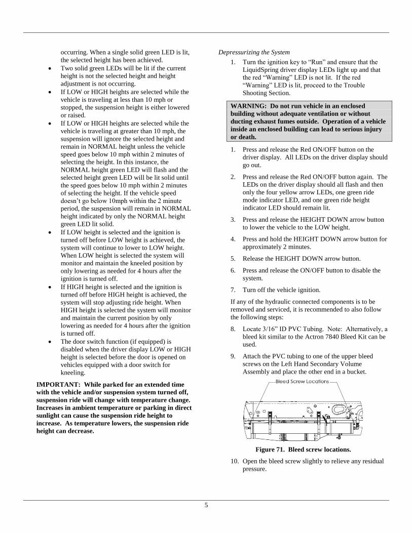
Depressurizing the System
1. Turn the ignition key to “Run” and ensure that the
LiquidSpring driver display LEDs light up and that
the red “Warning” LED is not lit. If the red
“Warning” LED is lit, proceed to the Trouble
Shooting Section.
WARNING: Do not run vehicle in an enclosed
building without adequate ventilation or without
ducting exhaust fumes outside. Operation of a vehicle
inside an enclosed building can lead to serious injury
or death.
1. Press and release the Red ON/OFF button on the
driver display. All LEDs on the driver display should
go out.
2. Press and release the Red ON/OFF button again. The
LEDs on the driver display should all flash and then
only the four yellow arrow LEDs, one green ride
mode indicator LED, and one green ride height
indicator LED should remain lit.
3. Press and release the HEIGHT DOWN arrow button
to lower the vehicle to the LOW height.
4. Press and hold the HEIGHT DOWN arrow button for
approximately 2 minutes.
5. Release the HEIGHT DOWN arrow button.
6. Press and release the ON/OFF button to disable the
system.
7. Turn off the vehicle ignition.
If any of the hydraulic connected components is to be
removed and serviced, it is recommended to also follow
the following steps:
8. Locate 3/16” ID PVC Tubing. Note: Alternatively, a
bleed kit similar to the Actron 7840 Bleed Kit can be
used.
9. Attach the PVC tubing to one of the upper bleed
screws on the Left Hand Secondary Volume
Assembly and place the other end in a bucket.
Figure 71. Bleed screw locations.
10. Open the bleed screw slightly to relieve any residual
pressure.

6
11. After pressure is relieved, close the bleed screw and
torque to 13-18 ft-lbs.
Notes:
Jacking up the chassis of a lowered, depressurized
chassis will cause a slight vacuum in the system and
minimize fluid loss while disconnecting hoses.
For service of non-hydraulic connected suspension
components, the suspension system can be first raised
to the HIGH height, appropriate jack stands placed
under the chassis, then depressurized as listed above
lowering the chassis onto the jack stands.
Calibrating the System
IMPORTANT: Proper calibration of the system must be
conducted with the vehicle loaded to the as delivered
condition with body installed. For calibration on an empty
chassis cab, LiquidSpring recommends weight be added to
the frame approximately equal to the planned body to
allow for proper bushing deflections.
Note: The LiquidSpring Calibration routine will automatically
determine maximum and minimum suspension ride height.
Based on those ride heights, the system will determine the
correct normal design ride height. The calibration system will
also calibrate the steering sensor.
1. Verify that the front wheels are steered straight
ahead.
2. Lower the vehicle to the ground and remove any jack
stands and any other obstructions from under the
vehicle.
3. To begin the calibration, turn the ignition key to
“Run” and ensure that the LiquidSpring driver
display lights up and that the red Error light is not
blinking.
WARNING: Do not run vehicle in an enclosed building
without adequate ventilation or without ducting exhaust
fumes outside. Operation of a vehicle inside an enclosed
building can lead to serious injury or death.
4. Press and release the Red ON/OFF button on the
driver display. All lights on the driver display should
go out.
5. Press and release the Red ON/OFF button a second
time. The lights on the driver display should all flash
then only show the four yellow arrow lights, one
green ride mode indicator, and one green ride height
indicator.
6. Press and hold both Ride Height Adjustment Buttons
simultaneously until the SPORT, COMFORT, HIGH,
and LOW green LED’s begin to flash. The
suspension system will begin to rise to the full high
position, and then lower to the full lowered position.
7. After the system completes the calibration routine,
the suspension will return to the original ride height.
8. Turn off the ignition for at least 3 minutes. Note:
The suspension system will not use the calibrated
ride height settings until power has been cycled.
Note: Pressing the red ON/OFF button on the driver
display does not cycle power to the LiquidSpring
suspension system, but only will enable/disable the
system.
9. Turn the ignition back to Run, then press the Red
ON/OFF button twice and verify the suspension
system moves to the new and correct ride height.
10. Calibration is now completed.
Calibrating the Steering Sensor Only
Note: The yellow lights are only lit when the steering sensor
indicates the center location. They will not be lit during the
rest of the travel.
IMPORTANT: The LiquidSpring CLASS® system
includes an automatic self-centering routine. In conditions
such as driving on highway with significant side wind, the
yellow lights may temporarily not be lit when the steering
wheel is exactly centered. Rotate slowly from center to full
steering stop, then repeat the opposite direction. If the
yellow lights momentarily light up during the travel, in one
or the other direction, the system is operating normally
and the steering sensor does not need to be manually re-
centered. Continue operating normally.
If the yellow lights do not light up at all during turning
the steering wheel, following the instructions below.
1. Verify that the front wheels are steered straight
ahead.
2. To begin the calibration, turn the ignition key to
“Run” and ensure that the LiquidSpring driver
display lights up and that the red “Warning” LED is
not lit or flashing.
WARNING: Do not run vehicle in an enclosed building
without adequate ventilation or without ducting exhaust
fumes outside. Operation of a vehicle inside an enclosed
building can lead to serious injury or death.
3. Press and release the Red ON/OFF button on the
driver display. All LEDs on the driver display should
go out.
4. Press and release the Red ON/OFF button again. The
LEDs on the driver display should all flash and then
only the four yellow arrow LEDs, one green ride
mode indicator LED, and one green ride height
indicator LED should remain lit.

7
5. Press and hold both Ride Height Adjustment Buttons
simultaneously until the SPORT, COMFORT, HIGH,
and LOW green LED’s begin to flash.
6. As soon as the four green LED’s begin to flash, press
the ON/OFF button to stop the process.
7. Verify that the four yellow arrow LED’s are lit.
8. Steering calibration is completed.
Bleeding the System
1. Verify system is turned OFF by either pressing the
ON/OFF button on the driver interface until the lights
are turned off or turning the ignition off.
2. Locate 3/16” ID PVC Tubing (not included with kit).
Note: Alternatively, a bleed kit similar to the Actron
7840 Bleed Kit can be used.
3. Attach the PVC tubing to one of the upper bleed
screws on the Left Hand Secondary Volume
Assembly and place the other end in a bucket.
Figure 3. Bleed screw locations.
4. Open the bleed screw slightly.
5. After air bubbles are no longer present, close the
bleed screw and torque to 13-18 ft-lbs.
6. Repeat with remaining bleed screws. Note: the
system may need to powered on and allowed to re-
pressurize.
7. Repeat with other side.
Checking Fluid Level
1. Turn the ignition key to “Run” and ensure that the
LiquidSpring driver display LEDs light up and that
the red “Warning” LED is not lit. If the red
“Warning” LED is lit, proceed to the Trouble
Shooting Section.
WARNING: Do not run vehicle in an enclosed
building without adequate ventilation or without
ducting exhaust fumes outside. Operation of a vehicle
inside an enclosed building can lead to serious injury
or death.
2. Press and release the Red ON/OFF button on the
driver display. All LEDs on the driver display should
go out.
3. Press and release the Red ON/OFF button again. The
LEDs on the driver display should all flash and then
only the four yellow arrow LEDs, one green ride
mode indicator LED, and one green ride height
indicator LED should remain lit.
4. After the suspension system stops leveling, check the
fluid level in the reservoir. If low, fill to the
indicated line.
Figure 4. Final fill fluid level.
5. To add fluid, remove filler/breather cap on reservoir.
6. Locate a container of Compressible Fluid.
7. Add fluid to the reservoir until the fluid level is
within the band shown in Figure 4.
Note. LiquidSpring Compressible Fluid is shipped in
1 gallon containers compatible with hand pumps such
as Autotec 57429.
8. Replace filler/breather cap and retighten.

8
Checking Fittings for Leaks
WARNING: The system operates under high fluid
pressure (up to 3500 psi). Do not attempt to locate leaks
by feeling with hands or any part of the body. High
pressure fluids can penetrate the skin and cause severe
tissue damage.
1. While system is at ride height and pressurized,
visually examine fittings and hose connections for
any source of leaks. Do not use hands to search for
leak. If the source of the leak is a fitting or other
component, depressurize the system and repair or
replace as needed.
2. Tighten hose nuts if the leak is coming from the
connection between the hose nut and a fitting.
Depressurize the system before tightening anything.
Replace hose if the leak is coming from anywhere
else on the hose.
WARNING: Never tighten a hydraulic fitting or hose
under pressure. Always depressurize the system before
adjusting fittings and hoses.
3. Clean all fluid from hose and fittings to visually
identify any leaks.
IMPORTANT: Over-tightening hoses and fittings can
damage components and lead to leaks.
See Installation Manual for additional instructions.
Service Intervals
Once Daily or Before Each Shift of Usage
Check the suspension system to be sure it is fully
operational.
o After starting vehicle, verify all LED’s on
the driver display flash briefly, then the
Green Ride Height and Ride Mode LED’s
are lit and the Red Warning LED does not
stay on or flash.
o Verify the four Yellow LED’s are lit when
the steering wheel is centered.
o Verify that they system is at NORMAL ride
height, with a steady green LED.
If the Driver Display indicates a
blinking ride height LED, allow the
system to complete leveling as
indicated by a steady green LED.
If LOW or HIGH height is shown
with a solid green LED, use the
arrow buttons to raise or lower the
suspension to NORMAL height.
Refer to Troubleshooting Section.
Visually inspect struts, hoses, and fittings for signs of
leakage.
o For leakage resulting in fluid pooled on the
floor greater than 1” in diameter, it is
recommended to service the system
immediately.
o For signs of leakage or weeping that results
in wetness on components or a single drop,
it is recommended to monitor the leak and
schedule repair service accordingly.
Initial 1,000 mile (1,600 km) Inspection
Inspect bolts and nuts at the control arm pivots to
assure they are properly torqued.
Inspect u-bolts to assure they are properly torqued.
Thoroughly inspect all hydraulic connections for
signs of leakage.
Inspect reservoir fluid level.
Routine Maintenance 25,000 miles (40,000 km) or 6 month
maximum Interval
Check all suspension components for any signs of
damaged/broken components, looseness, or wear.
Inspect bolts and nuts at the control arm pivots to
assure they are properly torqued.
Inspect u-bolts to assure they are properly torqued.
Thoroughly inspect all hydraulic connections for
signs of leakage.
Inspect reservoir fluid level.

9
Maintenance Record
Date of Purchase Name and Address of Dealer
Model of Vehicle Vehicle Identification Number (VIN)
Suspension Model Number Suspension Serial Number
Date Mileage Service Performed

10
Troubleshooting
The LiquidSpring CLASS® system includes on-board diagnostics to assist in pin-pointing potential issues. When a fault in the system
occurs, the red warning light on the Drivers Interface will light along with one or more of the other lights on the interface.
Driver Interface
Lights
Condition Cause Correction
Warning +
RIDE: SPORT
Battery Voltage in
excess of 16VDC
Vehicle charging system providing incorrect
voltage. Inspect and replace as necessary.
LiquidSpring system not connected to 12VDC
electrical system Inspect and replace as necessary
Warning +
RIDE: NORMAL
Pump Motor runs in
excess of 3 minutes See Issues with Vehicle Raising/Pump Section See Issues with Vehicle Raising/Pump Section
Warning +
RIDE: COMFORT
Battery Voltage below 9
VDC Vehicle charging system providing incorrect voltage Inspect and replace as necessary
Low vehicle battery Inspect and replace as necessary
Warning +
HEIGHT: HIGH
Issue with Right Hand
Height Sensor See Issues with Height Sensors Section See Issues with Height Sensors Section
Warning +
HEIGHT: NORMAL
System kneels in excess
of 3 minutes without
suspension movement
See Issues with Vehicle Lowering/Dump Valve
Section
See Issues with Vehicle Lowering/Dump Valve
Section
Warning +
HEIGHT: LOW
Issue with Left Hand
Height Sensor See Issues with Height Sensors Section See Issues with Height Sensors Section
Slow or Fast Blinking
Warning Light
Driver Interface cannot
communicate with ECU. See Issues with Driver Interface See Issues with Driver Interface
Issues with Vehicle Raising/Pump
Condition Cause Correction
Vehicle Leveled, Pump continues to run Pump motor shorted out. Contact LiquidSpring for further instructions.
Software issue Turn off ignition, wait 30 seconds, restart vehicle.
Excessive noise in height sensor See Issues with Height Sensors
Vehicle Not Leveled (or Raised), Pump
runs
Reservoir fluid level low Fill reservoir to specified level.
Hydraulic leak in system Check for fluid leaks and repair or replace.
Vehicle overloaded Check vehicle loading and correct.
Air in pump Check fluid level in reservoir and fill accordingly. Fully depressurize
system and restart leveling.
Internal leak in power module Replace power module.
Height sensor error See Issues with Height Sensors
Vehicle Not Leveled (or Raised), Pump
does not run System not turned on. Turn system on.
Blown fuse Check system fuses
Loss of electrical power Check wiring between power module and battery.
Pump runs for short time then stops Motor controller over temperature Contact LiquidSpring for further instructions.
Pump runs intermittently Loose connector or wiring Check wiring harness connections and battery connections. Repair as
necessary.
Issues with Vehicle Lowering/Dump Valve
Condition Cause Correction
Vehicle does not lower (kneel). System not turned on Turn system on
Blown fuse Check system fuses and replace as necessary
Obstacle under vehicle frame Remove obstacle
Wiring harness disconnected Check wiring harness connections and reconnect
Loss of electrical power Check wiring between power module and battery
Power module filters plugged Contact LiquidSpring for further instructions
Internal power module blockage Contact LiquidSpring for further instructions
Vehicle slow lowering (kneeling) Partial internal power module blockage Contact LiquidSpring for further instructions

11
Issues with One Corner Not Leveling Properly
Condition Cause Correction
One side will not raise or lower Internal power module blockage Contact LiquidSpring for further instructions
Low voltage Check battery voltage.
Wiring harness disconnected Check wiring harness connections and reconnect
Obstacle under vehicle frame Remove obstacle
Power module filters plugged Contact LiquidSpring for further instructions
Height sensor error See Issues with Height Sensors
One corner raises and lowers slower than
other corners Internal power module blockage Contact LiquidSpring for further instructions
Filter partially clogged Contact LiquidSpring for further instructions
Issues with Height Sensors
Condition Cause Correction
Vehicle or corner stops leveling at
incorrect height
Damaged height sensor and/or linkage Inspect height sensor components. Replace as necessary.
Incorrect calibration Recalibrate vehicle – see System Operation section.
Incorrect height sensor installation Inspect height sensor components and correct.
Corner height where leveling stops is
inconsistent Sensor or Linkage loose Inspect installation of height sensor and linkages and tighten if necessary
Loose connector / wire Inspect wiring between sensor and power module for loose connection
Vehicle will not level - no height sensor
signal
Height Sensor wiring shorted, broken, or
disconnected Inspect wiring between sensor and power module.
Malfunction in Sensor Replace sensor.
No Height Sensor Signal change while
driving Linkage broken/disconnected Inspect installation of height sensor and linkages. Correct and/or replace.
Issues with Ride/Handling
Condition Cause Correction
Vehicle rolls side to side excessively System inactive (Drivers interface dark) Turn system on (press On/Off button)
No electrical power to system Inspect and replace as necessary
Strut bushings worn Inspect and replace as necessary
Control arm bushings worn Inspect and replace as necessary
Sway bar bushings worn Inspect and replace as necessary
Strut mounting loose Inspect and replace as necessary
Rate Valve wiring shorted, broken, or
disconnected Inspect wiring and correct/replace as necessary.
Voltage to Rate Valve solenoid too low Check battery voltage.
Rate Valve Poppet Jammed open Contact LiquidSpring for further instructions
No vehicle speed signal See Issues with Vehicle Speed Signal section.
Excessive stiffness when on flat, straight
road Short to Rate Valve Check wiring between rate valve (on secondary volume) and power
module for signs of shorts. Replace as necessary.
Wiring to Rate Valve incorrect Inspect wiring and correct as necessary
Issues with Steering Sensor
Condition Cause Correction
No steering signal ( reduced roll control
when cornering)
Steering sensor wiring broke or
incorrect. Inspect wiring to steering sensor and correct as necessary.
Steering sensor malfunction Replace sensor
Steering sensor not installed correctly Inspect installation and correct as necessary
Yellow lights on driver display not lit
when steered straight ahead. Zero point of steering sensor incorrect. See Calibrating the Steering Sensor Only.
Intermittent steering sensor signal Loose connector / wire Check wiring between Steering sensor and Power module for loose
connection.

12
Issues with Vehicle Speed Signal
Condition Cause Correction
System leveling excessively while
driving.
Speed Sensor wiring shorted, broken, or
disconnected Inspect wiring and repair/replace as necessary
Speed signal malfunction Replace OEM speed sensor. See OEM service manual.
Intermittent speed sensor signal Loose connector / wire Check wiring between Speed sensor and Power module for loose
connection.
Issues with Vehicle Brake Signal
Condition Cause Correction
Vehicle will not level Brake signal wire not correctly tapped. Inspect wiring and repair/replace as necessary.
Brake switch malfunction Replace OEM speed sensor. See OEM service manual.
Intermittent leveling Loose connector / wire Inspect wiring and repair/replace as necessary.
Issues with Door Switch
Condition Cause Correction
Vehicle will not kneel when rear door
opened
Short or break in wiring between door
switch and power module. Inspect wiring and repair/replace as necessary.
Door switch malfunction Inspect door switch and repair/replace as necessary
Vehicle kneels whenever speed below
5mph
Short or break in wiring between door
switch and power module. Inspect wiring and repair/replace as necessary.
Door Switch out of adjustment Check installation of door switch and adjust as necessary
Door switch malfunction Inspect and replace per body builder instructions.
Intermittent door switch signal Loose connector / wire Inspect wiring and repair/replace as necessary.
Issues with Vehicle Ignition Signal
Condition Cause Correction
System does not turn on (no leveling or
stiffness control)
No ignition signal to controller or driver
interface Inspect wiring and repair/replace as necessary.
Ignition "sensor" malfunction Inspect and replace per OEM service manual.
System does not turn off once ignition
switched off Signal side short to battery Inspect wiring and repair/replace as necessary.
Ignition "sensor" malfunction Inspect and replace per OEM service manual.
System intermittently works Loose connector / wire Inspect wiring and repair/replace as necessary.
Issues with Vehicle Park Signal
Condition Cause Correction
System will start up but won't level when
parked No park signal to controller Inspect wiring and repair/replace as necessary.
Park sensor malfunction Inspect and replace per OEM service manual.
System levels when stopped and not in
park Park signal always on Inspect wiring and repair/replace as necessary.
Park sensor malfunction Inspect and replace per OEM service manual.
Intermittent leveling when stopped in or
out of park
Loose connector / wire Inspect wiring and repair/replace as necessary.
Issues with Driver Interface
Condition Cause Correction
Warning light blinks, system appears to
level. CAN wires crossed or not connected. Inspect wiring and repair/replace as necessary.
Malfunctioning Driver Interface Inspect and replace as necessary.
Warning light blinks, system does not
appear to operate (level) No power to ECU (5A 18ga Red Wire) Inspect wiring and repair/replace as necessary.
No ignition signal to ECU (Yellow Wire) Inspect wiring and repair/replace as necessary.
CAN wires crossed or not connected. Inspect wiring and repair/replace as necessary.

13
Issues with Power Module
Condition Cause Correction
Pump exhibits high pitch whine
immediately after pump stops or when vehicle lowering
The Check Valve is stuck open Replace Power Module
Pump running under heavy load and
leveling slow The Check Valve is only partially open Replace Power Module
Pump running under heavy load and no
leveling The Check valve is stuck closed Replace Power Module
Hydraulic fluid leaking from Power
Module O-ring failure Replace O-ring
Manifold cracked Replace Power Module
Fitting loose Tighten fittings
Valve loose Tighten valves to correct torque
Bolts between manifolds loose/broken Replace and /or tighten bolts to correct torque
Hydraulic line loose Tighten hydraulic line correctly
Bolts between reservoir and manifold
loose/broken Replace and/or tighten bolts to required torque
Broken / cracked reservoir Replace reservoir
Issues with Strut Assembly
Condition Cause Correction
Hydraulic Leak Weld failure between cylinder and end Replace strut
Cylinder fracture Replace strut
Threads stripped between cylinder and
gland Replace strut
Seals worn out Replace strut
Rod severely scratched or dented Replace strut
Fitting loose Tighten or replace fittings
Hose failure Replace failed hose
Hose cut Replace failed hose
Rod broken at bushing housing Weld failure Replace strut
Rod doesn't move freely in/out cylinder Piston jammed in cylinder Replace strut
Rod moves very easily in/out cylinder Piston broken therefore no damping Replace strut
Reduced damping level Damping components broken/worn out Replace strut
Strut upper mount not securely attached
to frame or Strut
Bolts attaching bracket to frame broken /
came out Replace bolts and tighten to required torque
Bolt attaching strut to bracket broke /
came out Replace bolts and tighten to required torque
Weld Failure Replace strut upper mount
Structural failure Replace strut upper mount
Strut lower mount not securely attached
to axle or strut
Bolts attaching bracket to axle broken /
came out Replace bolts and tighten to required torque
Bolt attaching strut to bracket broke /
came out Replace bolts and tighten to required torque
Weld Failure Replace strut lower mount
Structural failure Replace strut lower mount
14
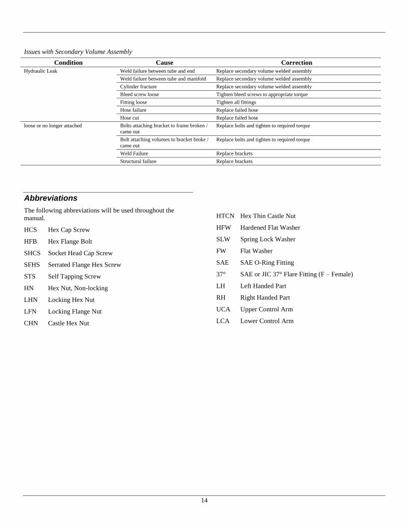
Issues with Secondary Volume Assembly
Condition Cause Correction
Hydraulic Leak Weld failure between tube and end Replace secondary volume welded assembly
Weld failure between tube and manifold Replace secondary volume welded assembly
Cylinder fracture Replace secondary volume welded assembly
Bleed screw loose Tighten bleed screws to appropriate torque
Fitting loose Tighten all fittings
Hose failure Replace failed hose
Hose cut Replace failed hose
loose or no longer attached Bolts attaching bracket to frame broken /
came out Replace bolts and tighten to required torque
Bolt attaching volumes to bracket broke /
came out Replace bolts and tighten to required torque
Weld Failure Replace brackets
Structural failure Replace brackets
Abbreviations
The following abbreviations will be used throughout the
manual.
HCS Hex Cap Screw
HFB Hex Flange Bolt
SHCS Socket Head Cap Screw
SFHS Serrated Flange Hex Screw
STS Self Tapping Screw
HN Hex Nut, Non-locking
LHN Locking Hex Nut
LFN Locking Flange Nut
CHN Castle Hex Nut
HTCN Hex Thin Castle Nut
HFW Hardened Flat Washer
SLW Spring Lock Washer
FW Flat Washer
SAE SAE O-Ring Fitting
37° SAE or JIC 37° Flare Fitting (F – Female)
LH Left Handed Part
RH Right Handed Part
UCA Upper Control Arm
LCA Lower Control Arm

15
Part Identification:
DS137FS2

16
Bill of Materials
DS137FS2
ITEM QTY PART NUMBER DESCRIPTION ITEM QTY PART NUMBER DESCRIPTION
1 1 10002-550 HB .875-9x5.500, Gr. 8 37 1 10762-008 Bridge
2 1 10002-850 HB .875-9x8.500, Gr. 8 38 1 10782-007 Crossmember Reinforcement
3 8 10003-004 HB 1.000-8x6.500, Gr. 8 39 1 10789-012 Track Rod Mount
4 2 10004-024 LHN 1/4-20, Gr. 2, CntrLck 40 1 10790-010 USM, LH
5 2 10006-003 HFW .875 41 1 10790-022 USM, RH
6 6 10006-004 HFW 1.000 42 1 10804-001 Spiral Cable Wrap, .375 OD x 12" L
7 8 10012-003 LFN 1-8, Gr G, Top Lock 43 2 10804-002 Spiral Cable Wrap, .375 OD x 8" L
8 11 10012-005 LFN 3/8-16, Gr G 44 1 10811-010 Frame Drill Template F450/F550
9 8 10012-007 LFN 1/2-13, Gr. G 45 1 10815-001 Fused Battery Lead
10 23 10012-008 LFN 5/8-11 Gr G 46 4 10830-013 Volume Mount
11 14 10012-010 LFN 5/16-18, Gr. G 47 4 10843-003 T-Bolt Clamp, Range 4.88-5.5
12 8 10012-012 LFN 3/4-16, Gr. G 48 7 10855-002 Vinyl-Coated Loop Clamp, 1" ID
13 4 10012-014 LFN 3/4-10 Gr G 49 2 10855-003 Vinyl-Coated Loop Clamp, 5/8" ID
14 2 10012-017 LFN 7/8-9, Gr. G 50 2 10867-003 Jounce Bumper, 2.375"Dia x 3.00"T
15 4 10064-005 U-Bolt 3/4-16 x 9.03 Tri-8 51 2 10871-001 SLW M10
16 1 10474-001 Silicone Oil, 16 oz. Bottle 52 21 10874-175 HFB 5/8-11x1.750, Gr. 8
17 11 10501-150 HFB 3/8-16 x 1.500, Gr. 8 53 2 10874-350 HFB 5/8-11x3.500, Gr 8
18 2 10502-004 HFB M10-1.5 x 35 CL 10.9 54 4 10885-150 HFB 1/2-13x1.500, Gr. 8
19 2 10586-001 Height Sensor 55 4 10885-200 HFB 1/2-13x2.000, Gr. 8
20 1 10586-002 Steering Sensor 56 10 10886-100 HFB 5/16-18 x 1.000, Gr. 8
21 1 10587-002 Linkage 57 4 10886-125 HFB 5/16-18 x 1.25 Gr. 8
22 2 10587-008 Linkage, Opposite 58 1 10941-014 Power Supply
23 2 10591-001 Ball Stud, 10mm x 5/16-18 59 2 10947-007 Lower Axle Clamp
24 1 10597-021 Asy, 2nd Vol 50 x 450, LH 60 2 11012-003 HFB M12-1.75x55 CL 10.9
25 1 10597-022 Asy, 2nd Vol 50 x 450, RH 61 2 11102-400 HFB 3/4-10 x 4 Gr 8
26 1 10614-001 Cap, Breather 62 2 11102-600 HFB 3/4-10 x 6 Gr 8
27 8 10640-005 Bearing Spacer, 1.24 x .812 x .318 63 1 11111 Kit, Power Module Mounting
28 1 10669-002 U-Bolt, 1/4-20 x 2.438 x 1.375 Gr. 2 64 1 11114-001 Tie Plate Mount
29 1 10680-001 Driver Interface 65 1 11115-008 Tie Plate
30 1 10704-003 Wiring Harness, Dash 66 1 11185-001 Strut LH
31 1 10729-014 Front Hanger, RH 67 1 11185-002 Strut RH
32 1 10730-008 Front Hanger, LH 68 1 11198-001 Track Rod
33 1 10733-001 Steering Linkage Mount 69 1 11211 Kit, Document, F550
34 1 10741-001 Steering Sensor 70 2 11222-001 Lower Control Arm
35 1 10745-007 Axle Seat, LH 71 2 11222-002 Upper Control Arm
36 1 10745-008 Axle Seat, RH 72 1 10806-008 Fuel-Brake Line Relocation Bracket

17
DS147FS2

18
Bill of Materials
DS147FS2
ITEM QTY PART NUMBER DESCRIPTION ITEM QTY PART NUMBER DESCRIPTION
1 1 10002-550 HB .875-9x5.500, Gr. 8 38 1 10745-008 Axle Seat, RH
2 1 10002-850 HB .875-9x8.500, Gr. 8 39 1 10762-008 Bridge
3 8 10003-004 HB 1.000-8x6.500, Gr. 8 40 1 10782-007 Crossmember Reinforcement
4 2 10004-024 LHN 1/4-20, Gr. 2, CntrLck 41 1 10789-012 Track Rod Mount
5 2 10006-003 HFW .875 42 1 10790-010 USM, LH
6 6 10006-004 HFW 1.000 43 1 10790-022 USM, RH
7 8 10012-003 LFN 1-8, Gr G, Top Lock 44 1 10804-001 Spiral Cable Wrap, .375 OD x 12" L
8 11 10012-005 LFN 3/8-16, Gr G 45 2 10804-002 Spiral Cable Wrap, .375 OD x 8" L
9 8 10012-007 LFN 1/2-13, Gr. G 46 1 10811-010 Frame Drill Template F450/F550
10 23 10012-008 LFN 5/8-11 Gr G 47 1 10815-001 Fused Battery Lead
11 14 10012-010 LFN 5/16-18, Gr. G 48 4 10830-013 Volume Mount
12 8 10012-012 LFN 3/4-16, Gr. G 49 4 10843-003 T-Bolt Clamp, Range 4.88-5.5
13 4 10012-014 LFN 3/4-10 Gr G 50 7 10855-002 Vinyl-Coated Loop Clamp, 1" ID
14 2 10012-017 LFN 7/8-9, Gr. G 51 2 10855-003 Vinyl-Coated Loop Clamp, 5/8" ID
15 4 10064-005 U-Bolt 3/4-16 x 9.03 Tri-8 52 2 10867-003 Jounce Bumper, 2.375"Dia x 3.00"T
16 1 10474-001 Silicone Oil, 16 oz. Bottle 53 2 10871-001 SLW M10
17 11 10501-150 HFB 3/8-16 x 1.500, Gr. 8 54 21 10874-175 HFB 5/8-11x1.750, Gr. 8
18 2 10502-004 HFB M10-1.5 x 35 CL 10.9 55 2 10874-350 HFB 5/8-11x3.500, Gr 8
19 2 10586-001 Height Sensor 56 4 10885-150 HFB 1/2-13x1.500, Gr. 8
20 1 10586-002 Steering Sensor 57 4 10885-200 HFB 1/2-13x2.000, Gr. 8
21 1 10587-002 Linkage 58 10 10886-100 HFB 5/16-18 x 1.000, Gr. 8
22 2 10587-008 Linkage, Opposite 59 4 10886-125 HFB 5/16-18 x 1.25 Gr. 8
23 2 10591-001 Ball Stud, 10mm x 5/16-18 60 1 10941-014 Power Supply
24 1 10597-013 Asy, 2nd Vol 108 x 539, LH 61 2 10947-007 Lower Axle Clamp
25 1 10597-014 Asy, 2nd Vol 108 x 539, RH 62 2 11012-003 HFB M12-1.75x55 CL 10.9
26 1 10614-001 Cap, Breather 63 2 11102-400 HFB 3/4-10 x 4 Gr 8
27 8 10640-005 Bearing Spacer, 1.24 x .812 x .318 64 2 11102-600 HFB 3/4-10 x 6 Gr 8
28 1 10669-002 U-Bolt, 1/4-20 x 2.438 x 1.375 Gr. 2 65 1 11111 Kit, Power Module Mounting
29 1 10675-009 Asy, Hose, -4 x 129-7/8” 66 1 11114-001 Tie Plate Mount
30 1 10675-010 Asy, Hose, -4 x 176-1/2” 67 1 11115-008 Tie Plate
31 1 10680-001 Driver Interface 68 1 11177-003 Strut LH
32 1 10704-003 Wiring Harness, Dash 69 1 11177-004 Strut RH
33 1 10729-014 Front Hanger, RH 70 1 11198-001 Track Rod
34 1 10730-008 Front Hanger, LH 71 1 11211 Kit, Document, F550
35 1 10733-001 Steering Linkage Mount 72 2 11222-001 Lower Control Arm
36 1 10741-001 Steering Sensor 73 2 11222-002 Upper Control Arm
37 1 10745-007 Axle Seat, LH 74 1 10806-008 Fuel-Brake Line Relocation Bracket

19
Front Hangers
ITEM QTY PART NUMBER DESCRIPTION ITEM QTY PART NUMBER DESCRIPTION
1 8 10012-008 LFN 5/8-11 Gr. G 3* 1 10729-007 (S/N: 2001858 and Older) Front Hanger, RH
10729-014 (S/N: 2001859 and Newer)
2 8 10874-175 HFB 5/8-11x1.75”, Gr. 8 4* 1 10730-004 (S/N: 2001858 and Older) Front Hanger, LH
10730-008 (S/N: 2001859 and Newer)
*IMPORTANT: Items marked with Asterisk are non-interchangeable with Older/Newer serial numbers. See Appendix A:
Part Number Compatibility – Serial Number Cutoff, Page 33 for more information.

20
Upper Strut Mounts
ITEM QTY PART NUMBER DESCRIPTION ITEM QTY PART NUMBER DESCRIPTION
1 1 10790-022 USM, RH 6 8 10012-007 LFN 1/2-13, Gr. G
2 1 10790-010 USM, LH 7 4 10885-150 HFB 1/2-13 x 1.50”, Gr. 8
3 8 10012-008 LFN 5/8-11 Gr. G 8 1 10789-012 Track Rod Mount
4 8 10874-175 HFB 5/8-11x1.75”, Gr. 8 9 4 10885-200 HFB 1/2-13 x 2.00”, Gr. 8
5 1 10782-007 Crossmember Reinforcement
21
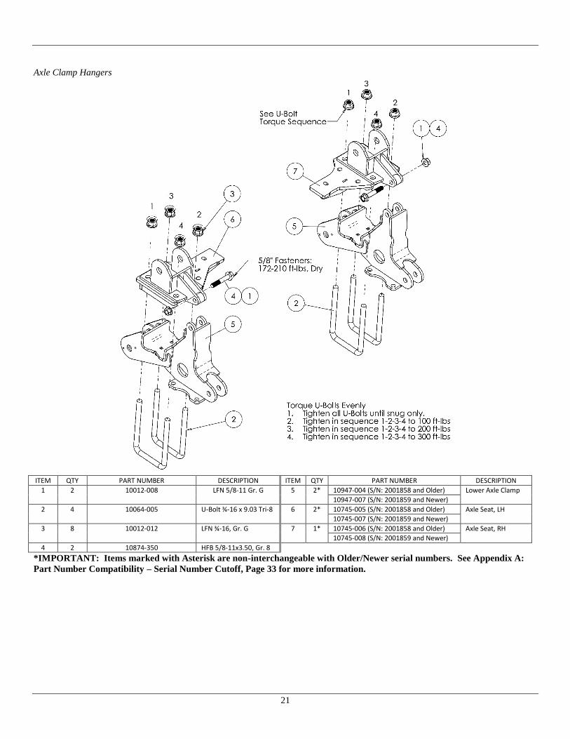
Axle Clamp Hangers
ITEM QTY PART NUMBER DESCRIPTION ITEM QTY PART NUMBER DESCRIPTION
1 2 10012-008 LFN 5/8-11 Gr. G 5 2* 10947-004 (S/N: 2001858 and Older) Lower Axle Clamp
10947-007 (S/N: 2001859 and Newer)
2 4 10064-005 U-Bolt ¾-16 x 9.03 Tri-8 6 2* 10745-005 (S/N: 2001858 and Older) Axle Seat, LH
10745-007 (S/N: 2001859 and Newer)
3 8 10012-012 LFN ¾-16, Gr. G 7 1* 10745-006 (S/N: 2001858 and Older) Axle Seat, RH
10745-008 (S/N: 2001859 and Newer)
4 2 10874-350 HFB 5/8-11x3.50, Gr. 8
*IMPORTANT: Items marked with Asterisk are non-interchangeable with Older/Newer serial numbers. See Appendix A:
Part Number Compatibility – Serial Number Cutoff, Page 33 for more information.
22
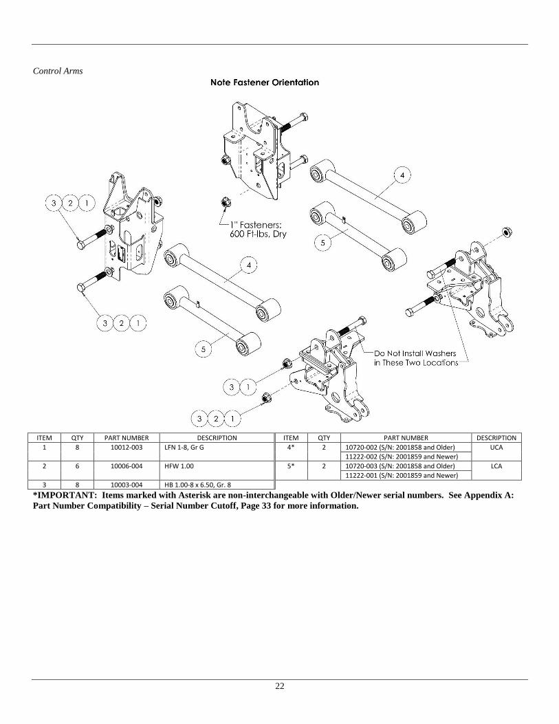
Control Arms
ITEM QTY PART NUMBER DESCRIPTION ITEM QTY PART NUMBER DESCRIPTION
1 8 10012-003 LFN 1-8, Gr G 4* 2 10720-002 (S/N: 2001858 and Older) UCA
11222-002 (S/N: 2001859 and Newer)
2 6 10006-004 HFW 1.00 5* 2 10720-003 (S/N: 2001858 and Older) LCA
11222-001 (S/N: 2001859 and Newer)
3 8 10003-004 HB 1.00-8 x 6.50, Gr. 8
*IMPORTANT: Items marked with Asterisk are non-interchangeable with Older/Newer serial numbers. See Appendix A:
Part Number Compatibility – Serial Number Cutoff, Page 33 for more information.

23
Bridge
ITEM QTY PART NUMBER DESCRIPTION ITEM QTY PART NUMBER DESCRIPTION
1 4 10012-008 LFN 5/8-11 Gr. G 3 2 11012-003 HFB M12-1.75x55 CL 10.9
2 4 10874-175 HFB 5/8-11x1.75”, Gr. 8 4 1 10762-008 Bridge
Track Rod and Tie Plate
ITEM QTY PART NUMBER DESCRIPTION ITEM QTY PART NUMBER DESCRIPTION
1 1 10012-008 LFN 5/8-11 Gr. G 8 1 11114-001 Tie Plate Mount
2 1 10874-175 HFB 5/8-11 x 1.75, Gr. 8 9 1 11115-008 Tie Plate
3 1 11198-001 Track Rod 10 1 10002-850 HB .875-9x8.500, Gr. 8
4 2 10006-003 HFW .875 11 1 10002-550 HB .875-9x5.500, Gr. 8
5 2 10012-017 LFN 7/8-9, Gr. G 12 1 10012-010 LHN 5/16-18 Gr. G
6 3 10012-005 LFN 3/8-16, Gr. G 13 1 10886-100 FHB 5/16-18 x 1.00 Gr. 8
7 3 10501-150 HFB 3/8-16 x 1.50, Gr. 8 14 1 10806-008 Fuel-Brake Line Relocation Bracket
24
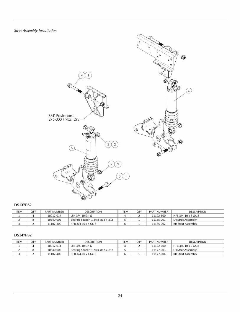
Strut Assembly Installation
DS137FS2
ITEM QTY PART NUMBER DESCRIPTION ITEM QTY PART NUMBER DESCRIPTION
1 4 10012-014 LFN 3/4-10 Gr. G 4 2 11102-600 HFB 3/4-10 x 6 Gr. 8
2 8 10640-005 Bearing Spacer, 1.24 x .812 x .318 5 1 11185-001 LH Strut Assembly
3 2 11102-400 HFB 3/4-10 x 4 Gr. 8 6 1 11185-002 RH Strut Assembly
DS147FS2
ITEM QTY PART NUMBER DESCRIPTION ITEM QTY PART NUMBER DESCRIPTION
1 4 10012-014 LFN 3/4-10 Gr. G 4 2 11102-600 HFB 3/4-10 x 6 Gr. 8
2 8 10640-005 Bearing Spacer, 1.24 x .812 x .318 5 1 11177-003 LH Strut Assembly
3 2 11102-400 HFB 3/4-10 x 4 Gr. 8 6 1 11177-004 RH Strut Assembly

25
Jounce Bumpers
ITEM QTY PART NUMBER DESCRIPTION ITEM QTY PART NUMBER DESCRIPTION
1 2 10867-003 Jounce Bumper, Ø2.375” x 3.00”T 3 2 10871-001 SLW M10
2 2 10502-004 HFB M10-1.5 x 35 CL 10.9
Height Sensors
ITEM QTY PART NUMBER DESCRIPTION ITEM QTY PART NUMBER DESCRIPTION
1 2 10586-001 Height Sensor 4* 2 10587-002 (S/N: 2001858 & Older) Asy, Linkage
10587-008 (S/N: 2001859 & Newer) Asy, Linkage, Opposite
2 2 10591-001 Ball Stud, 10mm x 5/16-18 5* 4 10886-175 (S/N: 2001858 & Older) HFB 5/16-18 x 1.75, Gr. 8
10886-125 (S/N: 2001859 & Newer) HFB 5/16-18 x 1.25, Gr. 8
3 6 10012-010 LFN 5/16-18, Gr. G
*IMPORTANT: Items marked with Asterisk are non-interchangeable with Older/Newer serial numbers. See Appendix A:
Part Number Compatibility – Serial Number Cutoff, Page 33 for more information.

26
Power Module Installation
ITEM QTY PART NUMBER DESCRIPTION ITEM QTY PART NUMBER DESCRIPTION
1 3 10012-011 LFN 3/8-16, Gr. G, Nylon Top 8 1 10799-014 Manifold Mount
2 2 10088-001 FW #10 9 2 10805-004 Grommet, .19 ID x .56 OD x .375 T
3 2 10252-003 SFHS 3/8-16 x .625, Gr 8 10 1 10865-003 J-Bolt, 3/8-16 x 4” L
4 2 10322-021 Hyd Fit 90, -4 37 x -4 37 F 11 1 10865-004 J-Bolt, 3/8-16 x 6” L
5 1 10501-002 HFB 3/8-16 x 1.25, Gr 8 12 2 11207-002 HFB M5-0.8 x 12 CL 10.9
6 2 10510-002 STS #10-16 x .75, Hex Head 13 1 10941-014 Power Module
7 1 10798-014 Reservoir Mount

27
Secondary Volumes (DS137FS2)
ITEM QTY PART NUMBER DESCRIPTION ITEM QTY PART NUMBER DESCRIPTION
1 7 11012-010 LFN 5/16-18, Gr. G 7 4 10843-003 T-Bolt Clamp, Range 4.88-5.5
2 7 10886-100 HFB 5/16”-18 x 1.00” Gr 8 8 7 10855-002 Vinyl Coated Loop Clamp, 1” ID
3 1 10614-001 Breather Cap 9 2 10855-003 Vinyl Coated Loop Clamp, 5/8” ID
4 1 10597-021 Asy, 2nd Volume, LH 10 8 10012-005 LFN 3/8-16, Gr. G
5 1 10597-022 Asy, 2nd Volume, RH 11 8 10501-150 HFB 3/8-16 x 1.50, Gr. 8
6 4 10830-013 Volume Mount

28
Secondary Volumes (DS147FS2)
ITEM QTY PART NUMBER DESCRIPTION ITEM QTY PART NUMBER DESCRIPTION
1 8 10012-005 LFN 3/8-16, Gr. G 8 1 10675-010 Asy, Hose
2 7 11012-010 LFN 5/16-18, Gr. G 9 4 10830-013 Volume Mount
3 8 10501-150 HFB 3/8-16 x 1.50, Gr. 8 10 4 10843-003 T-Bolt Clamp, Range 4.88-5.5
4 1 10597-013 Asy, 2nd Volume, LH 11 7 10855-002 Vinyl Coated Loop Clamp, 1” ID
5 1 10597-014 Asy, 2nd Volume, RH 12 2 10855-003 Vinyl Coated Loop Clamp, 5/8” ID
6 1 10614-001 Breather Cap 13 7 10886-100 HFB 5/16”-18 x 1.00” Gr 8
7 1 10675-009 Asy, Hose

29
Steering Sensor Installation
ITEM QTY PART NUMBER DESCRIPTION ITEM QTY PART NUMBER DESCRIPTION
1 1 10587-002 Asy, Linkage 5 1 10669-002 U-Bolt, 1/4-20
2 1 10733-001 Steering Linkage Mount 6 2 10004-024 LHN 1/4-20, Gr. 2, Centerlock
3 1 10741-001 Steering Sensor 7 2 10886-100 HFB 5/16-18 x 1.00, Gr. 8
4 1 10586-002 Steering Sensor

30
Electrical Schematics

31

32
33
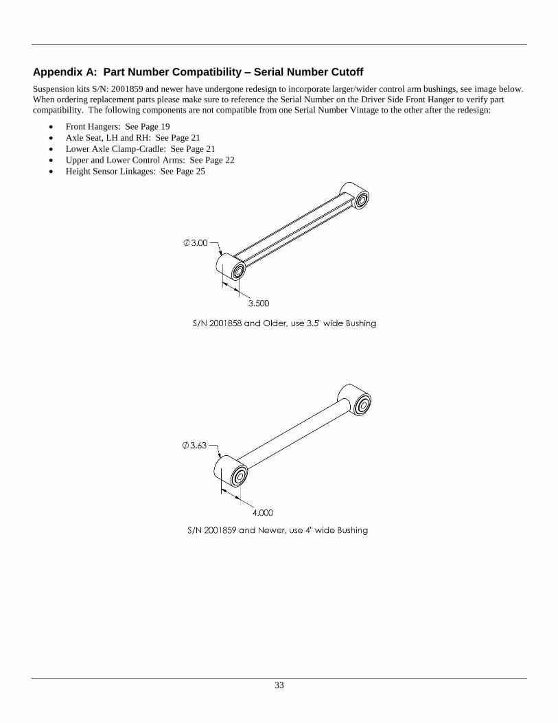
Appendix A: Part Number Compatibility – Serial Number Cutoff
Suspension kits S/N: 2001859 and newer have undergone redesign to incorporate larger/wider control arm bushings, see image below.
When ordering replacement parts please make sure to reference the Serial Number on the Driver Side Front Hanger to verify part
compatibility. The following components are not compatible from one Serial Number Vintage to the other after the redesign:
Front Hangers: See Page 19
Axle Seat, LH and RH: See Page 21
Lower Axle Clamp-Cradle: See Page 21
Upper and Lower Control Arms: See Page 22
Height Sensor Linkages: See Page 25

34

CLASS® Product Limited
Warranty
LIQUIDSPRINGTM
LLC
3416 RASCAL DRIVE
LAFAYETTE, IN 47909
PH: 765-474-7816, FAX: 765-474-7826
WWW.LIQUIDSPRING.COM
February 2016 Rev. E
Warranty Conditions
LiquidSpring LLC warrants that all CLASS® products shall be free of defects in material and workmanship provided the product has
been properly assembled, installed by a designated/qualified installer, properly maintained, serviced, and used normally for the given
application and within the rated capacities. The end user is responsible for operating, inspecting, and maintaining the product
according to applicable product and vehicle owner’s manuals and for instructing all operators and maintenance personnel on proper
use and maintenance.
Coverage
The starting date for warranty coverage will be the earlier date of the date purchased by the first end user or when the vehicle is put
into service and ends when the time period is reached in the warranty coverage period below. Proof of such date is the responsibility
of the first end user. If the starting date cannot be satisfactorily determined, then the date of product manufacture based on the product
serial number shall be used as the effective starting date.
Main Structural Components – 48 Months or 100,000 miles whichever occurs first.
Major structural components are defined as frame hangers, control arms, axle clamp group, transverse torque arm axle and
frame mounts, struts, and secondary volumes. All wear items such as bushings are excluded.
Other Components – 36 Months or 50,000 miles whichever occurs first.
Other components include all power module components, electrical harnesses, spring rate valves, hydraulic lines, and wear
items such as bushings and seals.
Labor – 12 Months
Estimated labor time and cost must be pre-approved prior to conducting warranty repair work for reimbursement
consideration.
Claims
1. Review warranty conditions and coverage to determine if component is warrantable.
2. Locate product serial number, warranty starting date (see Coverage above), vehicle manufacturer, mileage, and VIN.
3. Contact LiquidSpring LLC to address claim.
Components must be returned to LiquidSpring LLC Prepaid and identified with a LiquidSpring LLC issued Returned Goods
Authorization Number (RGA#) in order to qualify for reimbursement by LiquidSpring LLC. LiquidSpring LLC must authorize
all warranty repairs at a cost determined and approved by LiquidSpring LLC before any repairs are started.
Warranty Contact: (765) 474-7816
Limitations and Exclusions
The liability of LiquidSpring LLC under this limited warranty is solely limited to the repair or replacement of defective material and
workmanship by an authorized party. LiquidSpring LLC shall not be liable for use of non-LiquidSpring LLC components or for
repairs performed by unauthorized parties. This warranty does not include any expense of or related to transportation of parts outside
the Continental United States or compensation for inconvenience or loss of use while the product is being repaired. LiquidSpring LLC
shall not be liable for any expense, loss, or damage (direct, incidental, consequential or exemplary – including, but not limited to
towing expenses, travel expenses, vehicle rental, downtime expenses, incidental charges or any other losses arising in connection with
the sale, use or inability to use the product) resulting from the warranty-covered component found to be defective.
No expressed warranty is given by LiquidSpring LLC with respect to its product except at specifically set forth herein. Any warranty
implied by law, including any warranty of merchantability or fitness for particular purpose, is limited to the expressed warranty term
provided in the warranty coverage. The expressed warranty does not apply in the event of: use of non-LiquidSpring LLC replacement
components; improper installation, maintenance or repair; misuse, negligence, or abuse including but not limited to overloading,
unauthorized alterations or modifications.

CLASS® Product Limited
Warranty
LIQUIDSPRINGTM
LLC
3416 RASCAL DRIVE
LAFAYETTE, IN 47909
PH: 765-474-7816, FAX: 765-474-7826
WWW.LIQUIDSPRING.COM
February 2016 Rev. E
Warranty Labor Coverage
COMPONENT
ALLOWABLE
LABOR HOURS (*)
One Strut 0.75
Pair of Struts 1.50
Power module 1.00
Pressure relief valve 0.50
ECU (External) 0.50
ECU (Internal) 0.75
Height / Steering Sensor 0.50
Rate Valve 1.00
Track Rod Bushing 1.50
One Control Arm 1.50
Pair of Control Arm 2.00
(FOR ANY COMPONENT(s) NOT LISTED ABOVE, THE ALLOWABLE LABOR HOURS MUST BE APPROVED BY
LIQUIDSPRING LLC. PRIOR TO THE WORK BEING PREFORMED.)
*LABOR HOURS BASED ON $85.00 PER HOUR.
*LABOR FOR DIAGNOSIS WILL NOT BE COVERD WITHOUT PRIOR CONSENT FROM LIQUIDSPRING LLC.
Obtaining Warranty Parts
1. Obtain LiquidSpring LLC suspension serial number
(Located on driver’s side front hanger see Operator’s Manual for details)
2. Obtain mileage of suspension
3. Obtain In-service date of suspension
4. Give a detailed description of the problem
Contact LiquidSpring LLC
Service Dept.
Phone: 765-474-7816
Email: [email protected]


