Embed Size (px)
Citation preview
8/10/2019 IS 210.pdf
http://slidepdf.com/reader/full/is-210pdf 1/12
IS 210 : 1993
~~ ~T~ CPT~~T~lfT
- fqfwftSc;
( 'tfT~r ~;:nJ~ )
In dian S tandard
GREY IRON CASTING S-SPECIFICATION
( F ourth R evision)
U DC 6 69 '1 31 '6 -1 4
<0 BIS 1993
BUREAU OF INDIAN STANDARDS
MANAK BHA V AN, 9 BAHADUR SHAH ZAFAR MARG
NEW DELHI 110002
D ecem ber 1993
P rice G ro up
5
8/10/2019 IS 210.pdf
http://slidepdf.com/reader/full/is-210pdf 2/12
Pig Iron and Cast Iroll Sectional Commiltee, MTD 6
FOREWORD
This Indian Standard ( Fourth Revision) was adopted by the Bureau of Indian Standards, after the draft
finalized by the Pig Iron and Cast Iron Sectional Committee had been approved by the Metallurgical
E ngineering D ivision C ouncil.
This standard was first published in 195 and subsequently revised in 1962, 1970 and 1978. While
review ing ,this standard in the light of the experience gained during these years, the committee decided to
revise it to align w ith the present practices followed by the Indian industries and to bring it in line w ith
the other overseas standards.
The various diameters of test bar according to the section size of the castings have been replaced by a
single size of test bar. Guidance on the effect of section size of the casting on the tensile strength is, how-
ever, given in Annex A . A comparison between grades is given in Annex B.
The production of castings in the higher grades of grey cast iron often involves special techniques. It is
r( commended, therefore, that for either large or intricate caslings or a casting involving both these condi-
s, or where the castings have to withstand exception conditions, the grade of grey c, st iron selected and
any heat treatment involved should be agreed between the manufacturer and the purchaser. The higher
grades of grey cast iron ( that is, Grade FG300, FG350 and FG400 ) present special difficulties for section
10 mm and thinner.
For the benefit of the purchaser, typical properties of grey cast iron have been added in Annex C.
Information to be supplied by the purchaser while ordering grey iron castings according to this specification
is given in Annex D .
In the formulation of this standard assistance has been derived from ISO 185 'G rey Cast Iron
-
Specifi-
cation' issued by International O rganization for Standardization.
For the purpose of deciding whethn a particular requirement of this standard is complied w ith, the final
value, observed or calculated, expressing the result of a test or analysis, shall be rounded off in accordanc~
with IS 2 : 1960 'Rules for roundiDg off numerical values ( revised)'. The number of significant places
retained in the rounded off value should be the same as that of the specified value in this standard.
,
I

8/10/2019 IS 210.pdf
http://slidepdf.com/reader/full/is-210pdf 3/12
IS 210 : 1993
Ind ian Standa rd
GREY IRON CASTINGS -- SPECIFICATION
1 SCOPE
( F ourth R evision)
This standard covers the requirements for grey
i ro n c as ti ng s.
2 R EF rR EN CE S
The following Indian Standards are necessary
adjuncts to this standard:
IS No.
1387: 1993
1500 : 1983
2078: 1979
4843 : 1968
5139 : 1969
5519: 1979
I
]
3655 : 1993
Title
General requirements for the
supply of m etallurrgical m aterial
( secolld revis ion )
.
Method for BrineJl hardness test
for metallic materials (second
r ev is io n )
Method for tensile testing of
grey cast iron
( fi rs t r ev is io n)
Oode for designation of ferrous
castings
Recommended procedure for
repair of grey iron castings by
oxyacetylene and manual metal
a rc w eld in g
Deviations for untoleranced
dimensions of grey iron castings
f i r s t
revIsion)
Guidelines for heat treatment
of cast iron
3 SUPPLY OF MATERIAL
General requirements relating to the supply of
grey iron castings sha II be as laid down in
IS 1387: 1993.
4 G RA DE S
There shall be sellen grades of grey iron castings
nam('ly, G rades FG150. FG200, FG220, FG260,
FG300, FG350 and FG 400.
5 M A NU FA CT UR E
The castings shall be made by any process, as
agreed between the supplier and purchaser, that
will produce castings com plying w ith the require-
ments of this Indian Standard and shall be in
accordrnce w ith the pattern or working draw ing
as supplied by the purchaser.
6 CHEM ICAL COM POSITION
6.1 The composition of cast iron shall be left to
the discrecion of the manufactU rer, bu.t a maxi-
mum limit for phosphorus and/or sulphur may
be specified by the purchaser, if he so desires.
6.2 In case of special castings, the' detailed
chem ical composition shall be as agreed to be-
tween the purchaser and the m anufactur.er.
7 WORKMANSHIP AND FINISH
7.1 The castings shall be accurately moulded in
accordance w ith the pattern or working draw ings
supplIed by the purchaser, w ith the addition of
such letters, figures or marks as may be specified.
7.2 The purchaser shall specify tolerances,
m achining location and allowances with reference
to all important dimensions On other dimensions
tO lerances specified in IS 5519 : 1979 shall apply.
8 HEAT TREATMENT
Oastings are generally supplied w ithout having
any heat treatment. However, if required by the
purchaser, the heat treatment may be carried out
in accordance with 2 of IS 13655 : 1993,
9 M IC R OSTR U CTUR E
Where so required, the m icrostructure of grey
iron castings and the location for taking the
sample shall be as agreed to between the purcha-
ser and the m anufacturer.
10 FREEDOM FROM DEFECTS
10.1 The castings shall be sound, clean and free
from porosity, blow holes, hard spots, cracks, hot
tears, coldshU ts, distortion, sand and slag inclu-
sions and other harmful defects. They shall be
well-dressed and fettled; and shall be readily
machinable.
10.2 No welding or repairs shall be carried out
w ithout the prior perm ission of the purchaser.
W elding referred to here includes fusion welding
in accordance with the common foundry practice.
The method of repair by welding s e e IS 5139 :
1969) and subsequent stress-relieving shall be
as agreed to between the purchaser and the
manufacturer.
8/10/2019 IS 210.pdf
http://slidepdf.com/reader/full/is-210pdf 4/12
Group M ass of Indiv idual
Castings
]1 1
Up to 12'5
kg
21 )
Over
12'5
kg and
up to 50 kg
3'1
Over 50 kg and up to
500 kg
41 )
Over 500 kg
and lip
to 1 tODDe
5 Over 1 tonne
IS 210 : 1993
II PROVISION OF TEST BARS
11.1 A ll test bars shall be cast s~parately in sand
moulds and the nun,bfr of tcst bars required shall
bc as specified in 11. Tbey shall be ca,,( at the
same timc ar.d fn m the s'Im r. melt as
th ca'tings
t he v r ep re se nt .
11.2 The test bar material ,ball be iejpntifiable
,ith that of the castings represf'nted.
11.3 \Vhen castings are subjected to he'll treat-
ment, the test bars shall be heat-treated together
w ith the ca5tings they represent.
11.4 The test bars shall be cast in dr ied, baked or
chem ically bonded moulds made mainly or al)
agg. egate of siliceous sand with appropriate
binders. the average grain size of the sand shall
be approximate to that of the sand in which the
castings are pour~d. Moulds for the test bars shall
be approximat ely at room temperature when
poured. More than one test bar may be cast in a
single mould. but each bar in the mould shall be
surrounded by a thickness of sand which is not
less than the diameter of the bar.
12 FREQUENCY OF TESTING
12.1 The number of tests required for each melt
or batch of castings shall be as laid down in
Table I, various classes of castings being divided
into five representative groups according to mass.
12.2 In the case of large tonnage or castings
being produced can tinuously, the minimum
number of test bars to be provided shal1 be one
tensile test representing every two bours produc-
tion from a melting furnace.
Table 1 Number
of
Tests
( C lau se
12.1 )
Test Requirements
One te,t for each 500 kg
of castings or part thereof
One test for every 1 t onne
of castings or part thereof
One test for every 2 tonnes
of castings or part thereof
One test for every 3 tonnes
o f castings o r p2 .rt there of
One test for every 4 tonnes
of castings or part thereof
or one test fOf every
casting w eighing 4 tonnes
or m ore
llln addition Groups 1,2, 3 , and 4 all castings repre-
sented by one test shall be pour.-d from the same ladle
or same heat as the bar or bars provided for the test.
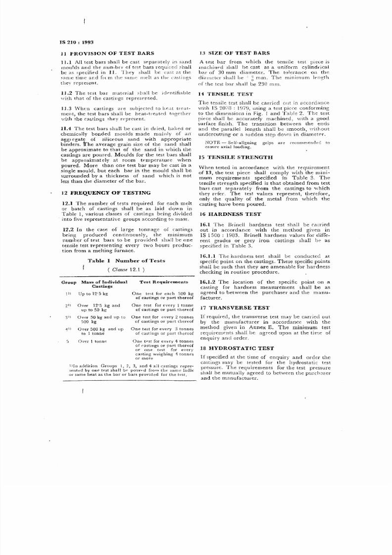
13 SIZE OF TEST BARS
A test bar from which the tensile test piece is
machin~d shall be cast as a uniform cylindrical
bar of 30 mm diameter. The tolerance on the
diamctn shal1 be g mm. The mmnnum lcngth
of the test bar sha l be 230 mm.
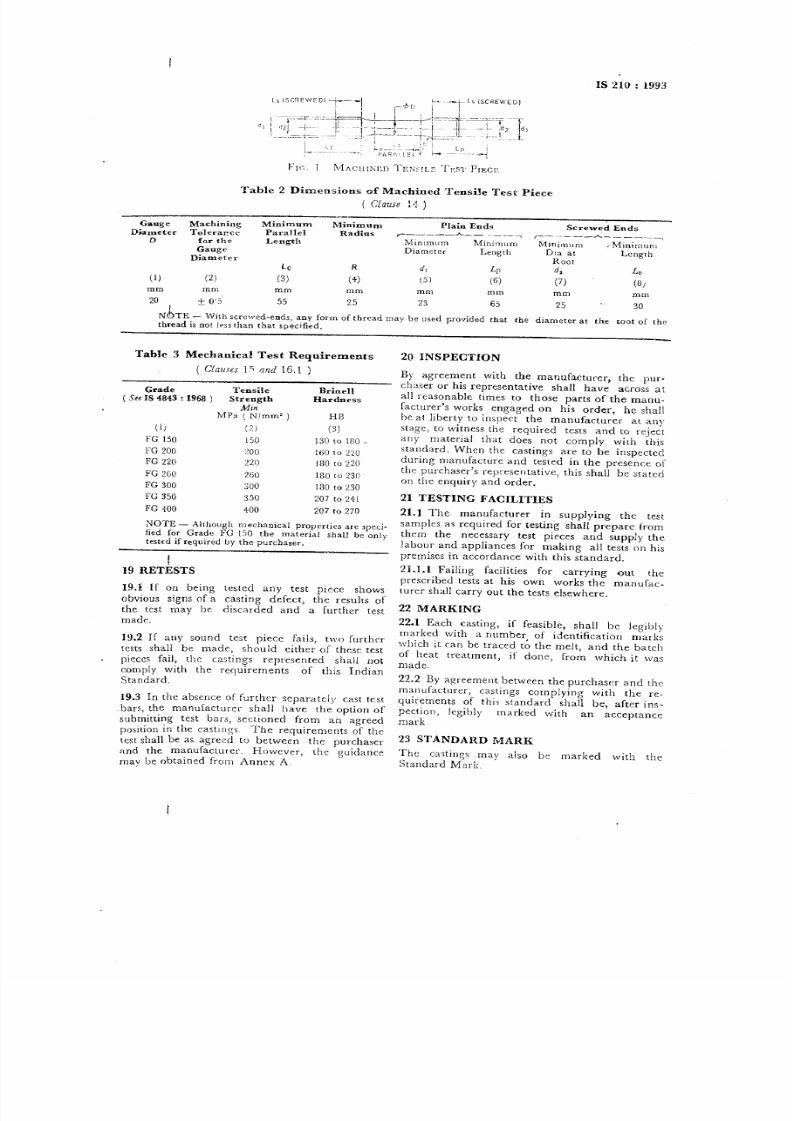
14 TENSILE TEST
The tensile test shall be carried out in
;)
ccorda:lce
w ith IS 2078 : 1979, using a test piece conform ing
to the dimensions in Fig.
1
and Tab1c 2. The test
piece shall be accurately machined, with a good
surface finish. The transition between the ends
and the paraJlel length shall be smooth, w ithout
undercutting or a sudden step down in diameter.
NOTE - Self-aligning grips are recommendn: to
e ns ur e a xi al l oa di ng .
15 TENSILE STRENGTH
vVhen tested in accordance with the requirement
of 13, the test piece shall comply with the mini-
mum requirements specified in Table 3. The
tensile strength specified is that obtained from test
bars cast separatel y from the castings to which
they refer. The test values represent, therefore,
only the quality of the metal from which the
casting have been poured.
16 HARDNESS TEST
16.1 The Brinell hardness test shall be carried
out in accordance with the method given in
IS 1500 : 1983. Brinell hardness values for diffe-
rent grades or grey iron castings shalJ be as
specified in Table 3.
16.1.1 The hardness test shall be conducted at
specific point on the castings. These specific points
shall be such that they are amenable for hardness
checking in routine procedure.
16.1.2 The location of the specific point on a
casting for hardness measurement shall be as
agreed to between the purchaser and the manu-
facturer.
17 TRANSVERSE TEST
If required, the transverse test may be carried out
by the manufacturer in accordance w ith the
method given in Annex E. The m inimum tcst
requiremrnts shall be agr-:ed upon at the time of
enquiry and order.
18 HYDROSTATIC TEST
If specified at the time of enquiry ancl order the
castings may be tested for the hydrostatic test
pressure. The requirements for the test pressure
shall be mutually agreed to between the purch~sel'
a nd th e m an ufa ctu re r.
8/10/2019 IS 210.pdf
http://slidepdf.com/reader/full/is-210pdf 5/12
Grade
Tensile
Brinell
IS 4843 : 1968
)
Strength
Hardness
Min
MPa
(
Nlmm'
)
HB
(1)
(2 )
(3)
FG 150
150
130 to 180 .
FG 200
ZO O
160 to 220
FG 220
no
130 to 220
FG 2GO
26 0
180 co 230
FG 300
30 0
180 to 230
FG 350
350
207 to 211
FG 100
400
207 to 270
IS 210 : 1993
Table
2 Dimensions
of Machined Tensile Test Piece
(
Clause
1
'1
)
Gauge
Dameter
D
Minim.um
Radius
Machining
Tolerar cc
for th e
Gauge
Djamet~r
Minimum
Parallel
Length
(I)
Lc
(3 )
R
(4 )
2)
mm m m
mm
mm
Plain Ends
r ,
N1inimum Minirnum
Diameter Lengtb
Screwed Ends
r---
,
M jnimum ~M jnimurn
D,a at Lengtb
Root
d, Ls
(7) (3)
d,
(5 )
L1 '
(6 )
mm
mm
mm
25
mm
20 + O 'S 55 25 23
NbTE --,\lith
screwed-ends, any form of thread may be used
thread is not less th an that spe cified.
65
30
provided that the diameter at the ~oot of the
Table 3 M echanical
Test Requirements
Clauses IS '1nd 16.1 )
NOTE
-
Altbough m echanical properties are 'peci-
tied for Grade FG
1:'0 tbe material shaIJ be only
(est€d if required by the purchaser.
I
19
RETESTS
19.1 If on being
obvious signs of a
the test may be
made.
]
9.2 If any sound test piece fails, two further
tests shall be made, should either of these test
pieces fail, the castings represented shall not
comply with the requirements of this Indian
Standard.
tested any test piece shows
casting defect, the results of
discarded and a further test
19.3 In the absence of further separately cast test
bars, the manufacturer shall have the option of
subm itting test bars, sectioned from an agreed
position in the castings The requirements of the
test shall be as agreed to between the purchaser
and the manufacturer. However, the guidance
may be obtained from Annex A .
2 0 IN SP EC TIO N
By agreement with the manufacturer, the pur-
chaser or his representative shall have across at
all reasonablt times to those parts of the manu-
facturer's works engaged on his order, he shall
be at liberty to inspect the manufacturer at any
stage, to witness the required tests and to reject
any material that does not comply w ith this
standard. When the castings are to be inspected
during manufacture and tested in the presence of
the purchaser's representative, this shall be slat cd
on the enquiry and order.
21 TESTING FACILITIES
21.1 The manufacturer in supplying the test
samples as required for testing shall prepare from
them the necessary test pieces and supply the
labour and appliances for making all tests on his
prem ises in accordance with this standard.
21.1.1 Failing facilities for carrying out the
prescribed tests at his own works the manufac-
turer sha)] carry out the tests elsewhere.
22 M ARK IN G
22.1 Each casting, if feasible, shall be legibly
marked with a number of identification mar ks
which it (an be traced t ~ the melt, and the balch
of heat treatment, if done, from which it was
made.
22.2 By agreement between the purchaser and the
manufacturer, castings complying w ith the re-
quirements of this standard shall be, after im -
pection, legibly marked with an acceptance
mark
23 STANDARD MARK
The castings may also be marked with the
Standard M ark.
8/10/2019 IS 210.pdf
http://slidepdf.com/reader/full/is-210pdf 6/12
IS 210 :11993
ANNEX A
( Foreword
an d
Clause
1 9.3 )
APPROXIMATE VARIATION OF STRENGTH
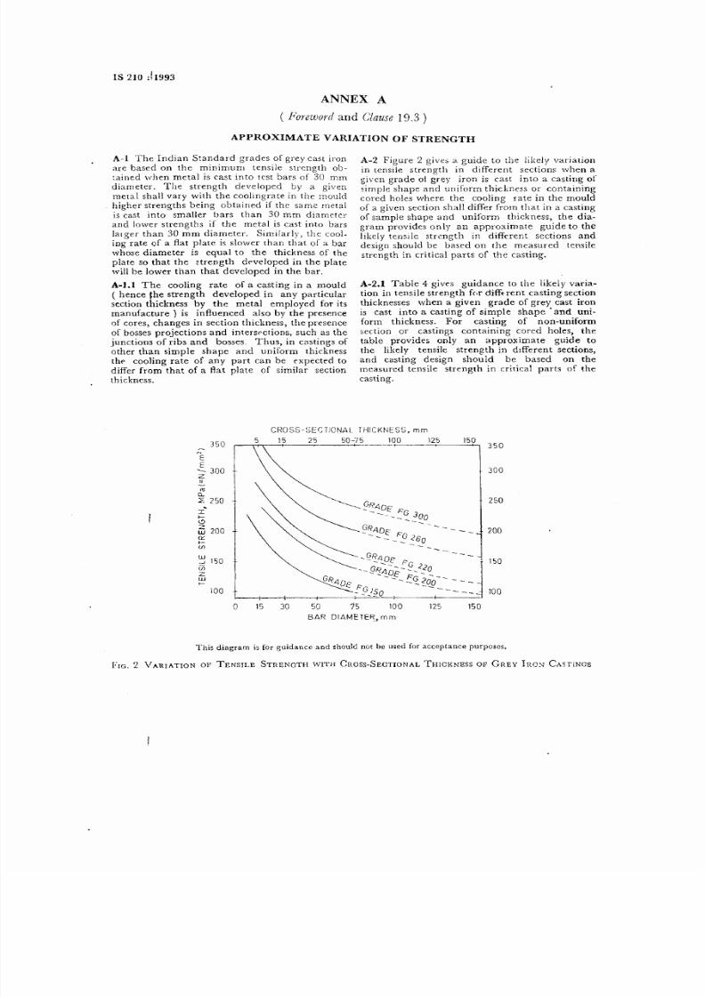
A-I The Indian Standard grades of grey cast iron
are based on the minimum tensile strength ob-
:ained when metal is cast into test bars of 30 mm
diameter. The strength developed by a given
metal shal1 vary w ith the coohngrate in the mould
higher strengths being obtained if the same metal
is cast into smaller bars than 30 mm diameter
and lower strengths if the metal is cast into bars
larger than 30 mm diameter. Sim ilarly, the cool-
ing rate of a flat plate is slower than that of a bar
whose diameter is equal to the thickness of the
plate so that the strength developed in the plate
'I'ill be lower than that developed in the bar.
A -I.I The cooling rate of a casting in a mould
( hence the strength developed in any particular
section thickness by the metal employed for its
manufacture) is influenced also by the presence
of cores, changes in section thickness, the presence
of bosses projections and inters<>ctions, such as the
junctions of ribs and bosses. Thus, in castings of
other than simple shape and uniform thickness
tht> cooJing rate of any part can be expected to
differ from that of a flat plate of sim ilar section
thickness.
E
E
30 0
z
o
a. .
:z :250
I
I-
~
~ 20 0
Ci :
,-
{)
~ 15 0
UJ
z
lJJ
>-
A-2 Figure 2 gives a guide to the likely variation
in tensile strength in different sections when a
given grade 01 grey iron is cast into a casting of
simple shape and uniform thickness or containing
cored holes where the cooJing rate in the mould
of a given section shall differ from that in a casting
of sample shape and uniform thickness, the dia-
gram provides only an approximate guide to the
likely tensile strength in different sections and
design should be based on the measured tensile
strength in critical parts of the casting.
A -2.1 Table 4 gives guidance to the likely varia-
tion in tensile strength f(,r diffuent casting section
thicknesses when a given grade of grey cast iron
is cast into a casting of simple shape' and uni-
form thickness. For casting of non-uniform
section or castings containing cored holes, the
table provides only an approximate guide to
the likely tensile strength in dtfferent sections,
and casting design should be based on the
measured tensile strength in critical parts of the
casting.
35 0
CRO SS-SECTIONA L THICKN ESS, m m
15 25 50-75 100 125
---+---~ +--
iOO
o
15 0
35 0
30 0
25 0
20 0
15 0
10 0
This diagram is for guidance and should not be used for acceptance purposes.
FIG. 2 V ARIATlON OF TENSILE STRENGTH W ITH CROss-SEcnONAL THICKNESS OF GREY I[W ~ CASTlNGS

8/10/2019 IS 210.pdf
http://slidepdf.com/reader/full/is-210pdf 7/12
Grade C astin g S ection T hick ne ss,
A nticipated T ensile
mm Strength
,--_
__ __ ..A .____________
MPa
(NimmO)
Over
Up to and
Including
FG 150
2'5
10
15~}
10
20
13 0
20
30 115
30
50
10 5
FG 200
25 10
20 5
10
20 180
20 30
16 0
30
50
14 5
FG 260
+'0
10
26 0
10
20
23 5
20
30
21 5
30
50
19 5
FG 300
10
20 270
20
30
2+ 5
30
50 225
loG 3 50
10
20
31 5
20
30
29 0
30
50 270
FG 350
350-
35
FG 300
30 0
30
FG 260
25 0
25
FG 220
FG 200
--200
-2 0
FGI50 ---
150~-
----15
MPa
(=Nfmm2)
IS 210 : 1993
Ta~le 4 Anticipated Tensile Properties for the Castings ( for Information Only)
( C la us e A-2. )
ANNEX B
( Fo reword )
M Pa
GRADE
(=N/mm2)
FG
1.00
---~---
1.00--
kgf/rnm2
--1.0
GRADE
1.0
35
30
25
20
15
CONVERSION F A C T O R
1N /mm2
=
1M Pa =0'1020 kg Imm2
Fr'~ . 3 COMPAnlsoN BETW EEN GHADRS IN THIS EDITION AND THE PREVIOUS EDITION
BASED ON M INIMUM TENSILE STRENGTH
8/10/2019 IS 210.pdf
http://slidepdf.com/reader/full/is-210pdf 8/12
Unit
Grade
.-- -------.---------- - -----~------~-----.....
1'G 15 0
1'0 200
1'0 220
FG 2GO
FG 300
FG 350
PG 400
MPa
( Njm m2 )
15 0
20 0
22 0
26 0
30 0
35 0
40 0
MPa
(
Nlmm2
)
4-2
56
62
73
84
98
1]2
MPa
(
Njmm'
98 130
14 3
16 9
19 5
22 8
26 0
Percent 0'60-0'751)
0 '48_0 '671) 0'39-0 631) 0 57 0'50
05 0
0'50
Percent
0'15
0'17
0 18
0 20
0'22
0-25
0'28
0'45-0'601) 0 '31_0'501 ) 0 '21 -0 '451 ) 0'37 0'28
0 '25 0 '28
MPa
( Nfmm2)
]2 0
16 0
17G
208
2.;0
28 0
32 0
MPa
( ~/mm2
)
GO O
no
76 8
86 4
960 I 080 I 200
MPa
(
Nfmm2
)
84 -
11 2 12 3 14 6 16 8 196 224
MPa
( N fm m2
)
19 5
26 0
28 6
33 8
39 0
45 5
52 0
MPa
( N (m m ')
17 3
23 0
25 3
29 9
:H 5
40 3
4G O
MPa
( N/mm2
)
17 3
23 0
25 3
29')
34 5
40 3
46 0
Percent
>4
>4
>4
>4
Up to 4
Up to 4
Up to 4-
OP a
10 0
11 4
12 0
12 8
13 5
140 145
GP a
10 0
1\4
12 0
12 8
13 5
14 0
14 5
GPa
40
46
48
51
54
56
58
+ - _ _ ~ _ _ _ _ _ _ _ _
0 26-~----------_;_---->-
:V [P a (
Njmm'
)
6
90
99
1\7
13 5
14 9
15 2
0
~ [P a (
N/mm '
)
G
(~
87
94 -
10 3
In
129 127
IS 210
;
19~3
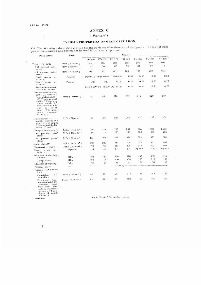
ANNEX C
( Foreword)
TYPICAL PROPERTIES OF GREY CAST I RON
C-l The foHowing informatiot1 is gi\'ct1 for thc guidat1cc of engin~ers and d~signcrs It does not form
pi'n of the standard and should not be U5~d for a~c p,ance pClrpo,~s:
P~'ope . .' ti c s
'~ .: .n s il c s fr ~n g th
O'U
I percent proof
stre~s
\I
percent proof
5tress
l'otal strain at
failure
~:::Iastic straJn at
failure
T ota l m in us e la stic
strain a t fa ilure
'
0tchc d ten s:le stre-
ngth (
see Note 2
)
'Circumferential
1-5Qitnotc b) root
radius 0'25 m m Or
Notch depth 2'5
mm . notch dia 20
m m .
or notch
depth 3'3
mm ,
notch diam eter
7 '/ ) 1 11 1n
)
C;rcurnfcreutiaJ
notch, Radius 9 '5
rom
( Notch depth
2-5 m rn, notch dia-
rneter 20 m n1
)
C om p re ss iv e s tr en gt h
n'l
percent proof
stress
0'1
percent proof
stress
S he ar s tre ng th
To r,iu nal strc ng th
Shea strain at
failure
M odulus of elasticity
Ten:;ion
Compression
M odlllJs of rigidity
Po isso n's ratio
Fatigue lim it
(
'Vah-
ler
)
~ innotchecl (8'4
mm dia)
V~notchcd (Cir.
qlm fercntial -i-50
V-notch \\lith
0.25 III D1 root
r ad iu s) D ia me te r
at notch g-4 m In
depth of notch
3',. mm)
J-J:,rdnc$S
l\1Pa
(
</mm'
)
15 0
20 0
22 0
:100
35 0
40 0
60
R efcr Table 3 for harclneos , a lu,'s
8/10/2019 IS 210.pdf
http://slidepdf.com/reader/full/is-210pdf 9/12
x 10 -6/K
X 10-6:K
X
10-61K
- -.---------
----~----1O-0 - --------+
1 0 0
)
-<-________________.____ll-O________~
1 1 0
)
S
., . _________________12-5_________-+
1 2'5 ) N ote 3 )
5 2 S
5 0 8
5 0 l
+ 8 8
+ 7 4
j . S 7
H , \ )
5 1 5
49'8
49-1
+7'8
+6'4
++'7
.,3'0
50':'
48'8
18'1
46'g
45'4'
'13'7
12'0
'19'5
47'8
i7' I
4:,'8
44'4
+2,7
41'0
48'5
i6'8
'16']
H '8
43'4
+ 1 '7
40'0
26 5
375
, 2 0
46 0
46 0 46 0
46 0
35 5
43 5
455 495 495 495
49 5
40 0
46 5
' 6 5
505 505
;,05
505
42 5
480 475
515
51 5
515 515
44-5
50 0
495 535
53 5
53 5
,,3:,
1-90
55.r>
56 0
G05 605
GaS
GOS
7'05
7'10
7 1 5
7'20
7'25
7'30
7'30
P. ope1..tl( s
C o(-fficic nt o r ther~
m a J e xp re ss io n
- 109°e
to Looe
,6°c [ 0 2 0D oe
200e to 100°C
Therma l conduct iv it y
100°C
LOOoe
300°C
oooe
5000e
S pe cific h ea t c ap ac ity
20° C to 200°C
20'e to 300'e
200e to 400°C
200e to 5000e
Looe
to 6 00 0e
200e to 7000e
-Re la ti ve d en si ty
\r fa gn et ic a nd e le c-
tric::..lprouerties
M aximum magne-
t ic p e rm e ab il it y
R~mflnent
magne~
usn\.
Coercive force
Hysceresis loss at
50 Hz
Elec tr ica l r c si st iv jt y
NOTES
Unit
\VImI'.
W/mK
W/mK
WlmK
\\ jmK
J/kgK
JlkgK
J/kgK
JjkgK
J/kgK
J 'k gK
i-LHlm
T
Aim
Jim'
Wlkg
i-LSlm
IS 210
: 1993
r de
c ~ ' ~-----.....
FC ; 150 FG 200 FG 220 FG 260 FG 300 FG 3')0 FG ~11~
301 to 380 ~-'-
-< 0'4 to 0'5 '0-
-<
560 to 720 ,. -+
-< 2500 to 3 000 +
-< 17'6 to 20 '9 +
0'800 0770 O '7CO 0'730 0'700 (\'070 O '64 1
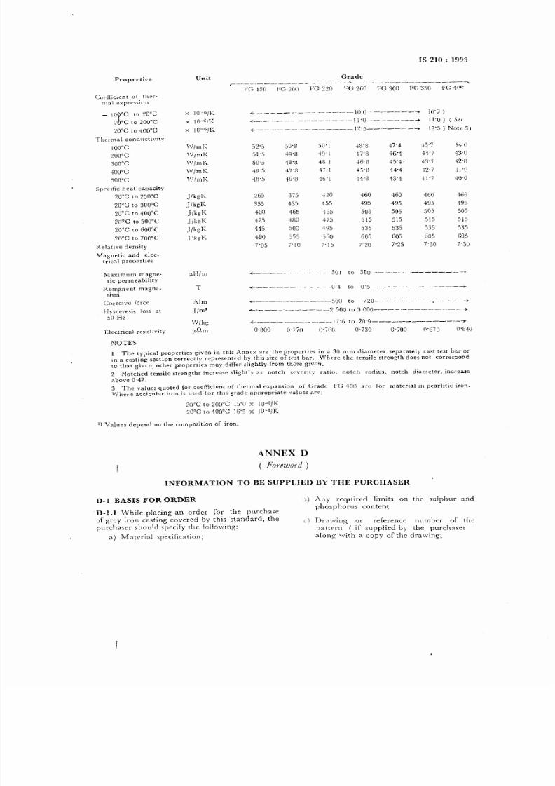
1 The typical properties given in this Annrx are the properties in a 30 mm diam eter separately cast test bar or
in a casting section correctl)' represent,d by this size of test bar, W hffe the tensile strength does not correspond
to that givrn, other propeflics m ay differ slightly from those given,
2 Notched tensile strengths increase slightly as notch s verity ratio, notch rzdius, notch diameter, increa..3e
above 0 4 7 ,
3 T h e v a l u e s quoted for coefiicient of therm al expansion of G rade FG 400 are for m aterial in pearJitic iron,
W here acclcuJar iron is used for this grade appropriate values are;
20 e to LOQoe
s'() X I O - G j K
20°C to 400°C 16'5 X 10⁻⁶/K
J)
Values depend on the composition of iron,
ANNEX D
(
Foreword)
D-l BASIS FOR ORDER
INFORMATION TO BE SUPPLIED BY THE PURCHASER
h) Any required lim its on the sulphur and
phosphorus content
D-LI
\Vhile placing an order for the purchase
of grey iron casting covered by this standard, the
;Jurchascr should specify the follow ing:
a) M a t e r ia l specification;
c) Drawing or reference number of the
pattern (if supplied by the purchaser
along with a copy of the drawing;
8/10/2019 IS 210.pdf
http://slidepdf.com/reader/full/is-210pdf 10/12
IS 210 : 1993
d) Tests required;
e) Whether the castings are to be inspected
and tested in the presence of the pu rch a-
se r' s repre sen ta ti ve ;
f) C ondition of delivery;
g) Any special requirement of the purchaser,
for example, hardness tests and locations
of non-destrur.tive testing, quality assu.
rance, etc; and
h) Test reports, if required.
ANNEX E
( Clause 17 )
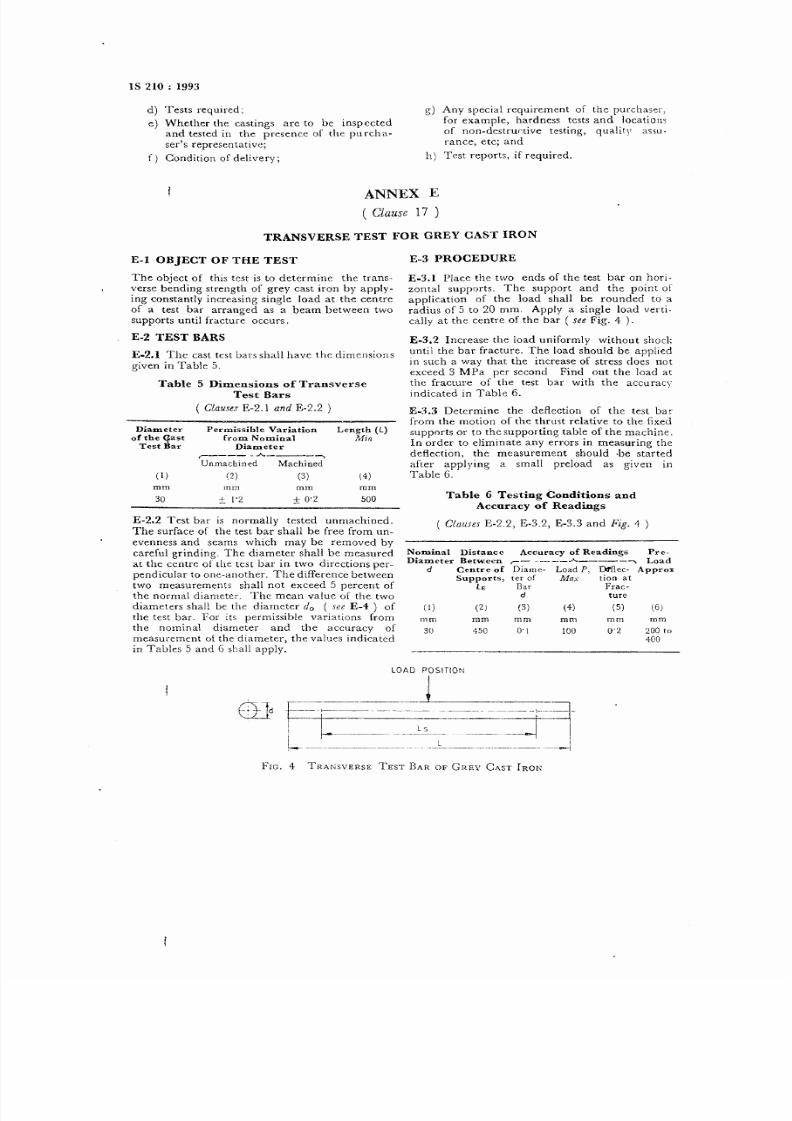
TRANSVERSE TEST FOR GREY CAST IRON
E-l OBJECT OF THE TEST
The object of this test is to determ ine the trans-
verse bending strength of grey cast iron by apply-
ing constantly increasing single load at the centre
of a test bar arranged as a beam between two
supports until fracture occurs.
E-2 TEST BARS
E-2.1 The cast tcst bars shal1 have the dimensions
given in Table 5.
Table 5 D im .ensions of Transverse
Test Bars
( C la us es E-2.l an d E-2.2
)
Diameter
of the qast
Test Bar
Perm issible Variation Length (L)
from N om inal Min
Diameter
, A 't
Uomacbioed Machined
(1 )
(2 )
(3 )
(4 )
rom
mm mmm
30
500
-
['2
:i 0 '2
E-2.2 Test bar is normally tested unmachined.
The surface of the test bar shall be free from un-
evenness and seams which may be removed by
careful grinding. The diameter shall be measured
at the centre of the test bar in two directions per-
pendicular to one-another. The difference between
two measurements shall not exceed 5 percent of
the norma diameter. The mean value of the two
diam eters shall be the diam eter d o s e e E-1) of
the test bar. For its perm issible variations from
the nominal diameter and the accuracy of
measurem ent of the diameter, the values indicated
in Tables 5 and 6 shall apply.
E -3 P RO CE DU RE
E-3. I Place the two ends of the test bar on hori-
zontal supports. The support and the point of
application of the load shall be rounded to a
radius of 5 to 20 mm. Apply a single load verti-
cally at the centre of the bar ( se e Fig. 4 ).
E-3.2 Increase the load uniform ly without shock
until the bar fracture. The load should be applied
in such a way that the increase of stress does not
exceed 3 MPa per second Find out the load at
the fracture of the test bar w ith the accuracy
indicated in Table 6.
E-3.3 Determ ine the deflection of the test bar
from the motion of the thrust relative to the fixed
supports or to the supporting table of the machine.
In order to elim inate any errors in measuring the
deflection, the measurement should .be started
after applying a small preload as given in
Table 6.
Table 6 Testing Conditions and
Accuracy
of R eadings
C l a u s e s
E-2 .2 , E -3 .2 , E -3 .3 and
Fig.
I}
)
Nom inal D istance
Diam eter Betw een
d Centre of
Supports,
LB
Accuracy of Readings Pre-
r-
__, A ,~
Load
Diam e- Load
P,
D fflec- A ppro
ter of Max tioo at
Bar Frac-
d ture
(3) (4) (5) (6)1) (2)
m m
mm mm mm
m m
om
30
45 0
0.2
200 to
40 0
10 0
L O A D P O S I T I O N
Fi
-. >-
9
--- -
I Ls--T
I
-
u_
,--~--
-- , ~ 1
,L
_~~
,'
u _L..~ ~
FIG. 4 TRANSVERSE TEST BAR OF GREY CAST IRON

8/10/2019 IS 210.pdf
http://slidepdf.com/reader/full/is-210pdf 11/12
E-4 TEST RESULT
The test report shall include:
a) load at fracture in C\;
b) bending strength
fb'
to an accuracy of O'::J
MPa calculated from the formula:
IS 210 : 1993
where
P
=
maximum load at fracLUre in N ,
1.8
distance between centres of supports
in mm, and
do
=
mean diameter in mm, and
c) deflection at fr2.cture in mm.
8/10/2019 IS 210.pdf
http://slidepdf.com/reader/full/is-210pdf 12/12
B ureau o f Ind ian S tand ard ,
B IS is a statutory institution established under the Bureau oJ Indian Standards Act, 1986 to promote
harm onious developm ent of the activities of standardization, m arking and quality certification of goods
and attending to connected matters in the country.
Copyright
BlS has tile copyright of all its publications. No part of these publications may be reproduced in any
form without the prior permission in writing of BIS. This does not preclude the free use, in the course
of implementing the standard, of necessary details, such as symbols and sizes, type or grade
designations. Enquiries relating to copyright be addressed to the Director ( Publications ), B IS.
R ev ie w o f I nd ia n S ta nd ard s
Amendmeljlts are issued to standards as the need arises on the basis of comments. Standards are also
reviewed periodically; a standard along with am endm ents is reaffirmed when such review indicates that
no changes are needed; if the review indicates that chaQges are needed, it is taken up for revision.
Users of Indian Standards should ascertain that they are in posse ssion of the latest amendments or
edition by referring to the latest issue of 'BIS Handbook' and 'Standards Monthly Additions'.
Comments on this Indian Standard may be sent to BIS giving the following reference:
Doc No. MTD 6 (3&57 )
Amen dmen ts Iss ue d S in ce P ub lic atio n
Am end N o.
Date of Issue
T ex t A ffe cte d
BUREAU OF INDIAN STANDARDS
Headq uarte rs :
M anak Bhavan, 9 Bahadur Shah Zafar M arg, New Delhi 110002
Telephones: 331 01 31, 331 13 75
R egional O ffice. I
Centralt Manak Bhavan, 9 Bahadur Shah Zafar M arg
NEW DELHI 110002
Te legrams : Manak sans th a
(
C ommon to a ll o ffic es)
Telephone
E astern: 1/14 C . 1. T . S che ':::V II M , V . 1. P . R oad, M aniktola
CALCUTTA 700054
~
331 01 31
~ 331 13 75
37 84 99, 37 85 61
37 86 26, 37 86 62
.
~
53 38 43, 53 16 4 0
~ 53 23 84
( 235 02 16, 235 04 42
~ 235 15 19, 235 23 15
{
632 92 95, 632 78 58
63278 9 . 632 78 92
Northern t SCO 445-446, Sector 3S-C, CHANDIGARH 160036
Southern I C. I. T . Campu., IV Croll Road, MADRAS 600113
W estern I Manakalaya, E9 M IDC, Marol, Andheri (
Ea.. )
B OM BA Y 400093
Branche. II AHMADABAD. BANGALORE. BHOPAL. BHUBANESHW AR.
COlMBATORE. PARIDABAD. GHAZIABAD. GUWAHATI. HYDERABAD.
JAIPUR. KANPUR. LUCKNOW. PATNA. THIRUVANANTHAPURAM .
Priut..>.:d.t N ew In Jia P 'i.n tin lf P re ... K tJ ud a.la Jit>