Embed Size (px)
Citation preview

Disclosure to Promote the Right To Information
Whereas the Parliament of India has set out to provide a practical regime of right to information for citizens to secure access to information under the control of public authorities, in order to promote transparency and accountability in the working of every public authority, and whereas the attached publication of the Bureau of Indian Standards is of particular interest to the public, particularly disadvantaged communities and those engaged in the pursuit of education and knowledge, the attached public safety standard is made available to promote the timely dissemination of this information in an accurate manner to the public.
इंटरनेट मानक
“!ान $ एक न' भारत का +नम-ण”Satyanarayan Gangaram Pitroda
“Invent a New India Using Knowledge”
“प0रा1 को छोड न' 5 तरफ”Jawaharlal Nehru
“Step Out From the Old to the New”
“जान1 का अ+धकार, जी1 का अ+धकार”Mazdoor Kisan Shakti Sangathan
“The Right to Information, The Right to Live”
“!ान एक ऐसा खजाना > जो कभी च0राया नहB जा सकता है”Bhartṛhari—Nītiśatakam
“Knowledge is such a treasure which cannot be stolen”
“Invent a New India Using Knowledge”
है”ह”ह
IS 1586-2 (2012): Metallic Materials - Rockwell HardnessTest, Part 2: Verification and Calibration of TestingMachines ( Scales A,B,C,D,E,F,G,H, K, N,T) [MTD 3:Mechanical Testing of Metals]


Hkkjrh; ekud
èkkfRod lkefxz;k¡ — jkWdosy dBksjrk ijh{k.kHkkx 2 ijh{k.k e'khuksa dk lR;kiu ,oa v'ka'kksèku
( LosQy A, B, C, D, E, F, G, H, K, N, T )
(pkSFkk iqujh{k.k )
Indian StandardMETALLIC MATERIALS — ROCKWELL
HARDNESS TESTPART 2 VERIFICATION AND CALIBRATION OF TESTING MACHINES
(SCALES A, B, C, D, E, F, G, H, K, N, T)
( Fourth Revision )
ICS 77.040.10
© BIS 2012
August 2012 Price Group 8
B U R E A U O F I N D I A N S T A N D A R D SMANAK BHAVAN, 9 BAHADUR SHAH ZAFAR MARG
NEW DELHI 110002
IS 1586 (Part 2) : 2012ISO 6508-2 : 2005
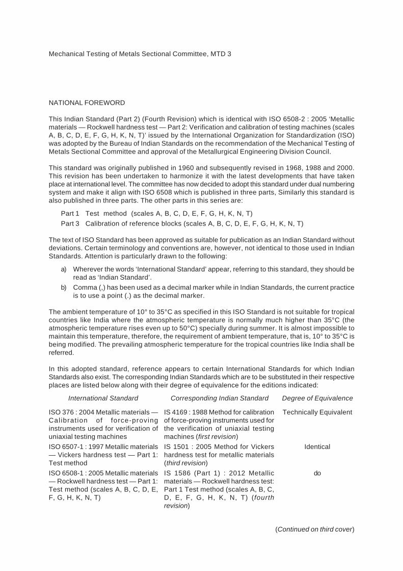
Mechanical Testing of Metals Sectional Committee, MTD 3
NATIONAL FOREWORD
This Indian Standard (Part 2) (Fourth Revision) which is identical with ISO 6508-2 : 2005 ‘Metallicmaterials — Rockwell hardness test — Part 2: Verification and calibration of testing machines (scalesA, B, C, D, E, F, G, H, K, N, T)’ issued by the International Organization for Standardization (ISO)was adopted by the Bureau of Indian Standards on the recommendation of the Mechanical Testing ofMetals Sectional Committee and approval of the Metallurgical Engineering Division Council.
This standard was originally published in 1960 and subsequently revised in 1968, 1988 and 2000.This revision has been undertaken to harmonize it with the latest developments that have takenplace at international level. The committee has now decided to adopt this standard under dual numberingsystem and make it align with ISO 6508 which is published in three parts, Similarly this standard isalso published in three parts. The other parts in this series are:
Part 1 Test method (scales A, B, C, D, E, F, G, H, K, N, T)Part 3 Calibration of reference blocks (scales A, B, C, D, E, F, G, H, K, N, T)
The text of ISO Standard has been approved as suitable for publication as an Indian Standard withoutdeviations. Certain terminology and conventions are, however, not identical to those used in IndianStandards. Attention is particularly drawn to the following:
a) Wherever the words ‘International Standard’ appear, referring to this standard, they should beread as ‘Indian Standard’.
b) Comma (,) has been used as a decimal marker while in Indian Standards, the current practiceis to use a point (.) as the decimal marker.
The ambient temperature of 10° to 35°C as specified in this ISO Standard is not suitable for tropicalcountries like India where the atmospheric temperature is normally much higher than 35°C (theatmospheric temperature rises even up to 50°C) specially during summer. It is almost impossible tomaintain this temperature, therefore, the requirement of ambient temperature, that is, 10° to 35°C isbeing modified. The prevailing atmospheric temperature for the tropical countries like India shall bereferred.
In this adopted standard, reference appears to certain International Standards for which IndianStandards also exist. The corresponding Indian Standards which are to be substituted in their respectiveplaces are listed below along with their degree of equivalence for the editions indicated:
International Standard Corresponding Indian Standard Degree of Equivalence
ISO 376 : 2004 Metallic materials —Calibrat ion of force-provinginstruments used for verification ofuniaxial testing machinesISO 6507-1 : 1997 Metallic materials— Vickers hardness test — Part 1:Test methodISO 6508-1 : 2005 Metallic materials— Rockwell hardness test — Part 1:Test method (scales A, B, C, D, E,F, G, H, K, N, T)
IS 4169 : 1988 Method for calibrationof force-proving instruments used forthe verification of uniaxial testingmachines (first revision)IS 1501 : 2005 Method for Vickershardness test for metallic materials(third revision)IS 1586 (Part 1) : 2012 Metallicmaterials — Rockwell hardness test:Part 1 Test method (scales A, B, C,D, E, F, G, H, K, N, T) (fourthrevision)
Technically Equivalent
Identical
do
(Continued on third cover)

1 Scope
This part of ISO 6508 specifies a method of verification of testing machines for determining Rockwell hardness (scales A, B, C, D, E, F, G, H, K, N, T) in accordance with ISO 6508-1.
It specifies a direct method for checking the main functions of the machine operation and an indirect method suitable for the overall checking of the machine. The indirect method may be used on its own for periodic routine checking of the machine in service.
If a testing machine is also to be used for other methods of hardness testing, it shall be verified independently for each method.
This part of ISO 6508 is applicable to portable hardness testing machines.
2 Normative references
The following referenced documents are indispensable for the application of this document. For dated references, only the edition cited applies. For undated references, the latest edition of the referenced document (including any amendments) applies.
ISO 376:2004, Metallic materials — Calibration of force-proving instruments used for verification of uniaxial testing machines
ISO 6507-1, Metallic materials — Vickers hardness test — Part 1: Test method
ISO 6508-1, Metallic materials — Rockwell hardness test — Part 1: Test method (scales A, B, C, D, E, F, G, H, K, N, T)
ISO 6508-3:2005, Metallic materials — Rockwell hardness test — Part 3: Calibration of reference blocks (scales A, B, C, D, E, F, G, H, K, N, T)
3 General conditions
Before a Rockwell hardness testing machine is verified, the machine shall be checked to ensure that it is properly set up in accordance with the manufacturer's instructions:
Especially it should be checked that:
a) the plunger holding the indenter is capable of sliding in its guide;
Indian StandardMETALLIC MATERIALS — ROCKWELL
HARDNESS TESTPART 2 VERIFICATION AND CALIBRATION OF TESTING MACHINES
(SCALES A, B, C, D, E, F, G, H, K, N, T)
( Fourth Revision )
IS 1586 (Part 2) : 2012ISO 6508-2 : 2005
1

b) the indenter-holder is firmly mounted in the plunger;
c) the test force can be applied and removed without shock or vibration and in such a manner that the readings are not influenced.
It shall be checked that the readings are not affected either by movements of the test piece or by deformation of the frame. When a device is supplied, which locks the test piece against the upper part of the frame, the locking force shall exceed the total test force. The influence of deformations may be checked by using a plunger with a spherical tip (diameter of at least 10 mm), instead of the indenter, bearing against the anvil through a spacer and using the locking device when it is supplied. The material of the plunger and of the spacer have a hardness of at least 60 HRC. The readings of the measuring system (with preliminary force applied) before application and after removal of the additional force shall not differ by more than 1,5 Rockwell units (without locking equipment) and 0,5 Rockwell units (with locking equipment).
4 Direct verification
4.1 General
4.1.1 Direct verification should be carried out at a temperature of (23 ± 5) °C. If the verification is made outside of this temperature range, this shall be reported in the verification report.
4.1.2 The instruments used for verification and calibration shall be traceable to national standards.
4.1.3 Direct verification involves:
a) calibration of the test force;
b) verification of the indenter;
c) calibration of the depth-measuring system;
d) verification of the testing cycle.
4.2 Calibration of the test force
4.2.1 The preliminary test force F0 (see 4.2.4) and each total test force F used (see 4.2.5) shall be measured, and, whenever applicable, this shall be done at not less than three positions of the plunger spaced throughout its range of movement during testing. The preliminary test force shall be held for at least 2 s.
4.2.2 Three readings shall be taken for each force at each position of the plunger. Immediately before each reading is taken, the plunger shall be moved in the same direction as during testing.
4.2.3 The forces shall be measured by one of the following two methods:
⎯ by means of a force proving device in accordance with ISO 376:2004, class 1, or
⎯ by balancing against a force, accurate to ± 0,2 %, applied by means of calibrated masses or by another method having the same accuracy.
4.2.4 The tolerance on the preliminary test force F0 (before application and after removal of the additional test force F1) shall be ± 2,0 %.
4.2.5 The tolerance on the total test force F shall be ± 1,0 %. Each individual value of F shall be within this tolerance.
IS 1586 (Part 2) : 2012ISO 6508-2 : 2005
2

4.3 Verification of the indenter
4.3.1 Diamond cone indenter (scales A, C, D, N)
To verify the reliable performance of the conical indenter in conformance with this part of ISO 6508, a direct and an indirect verification shall be carried out.
4.3.1.1 Direct verification
4.3.1.1.1 The surfaces of the diamond cone and spherical tip shall be polished for a penetration depth of 0,3 mm and shall blend in a truly tangential manner. Both surfaces shall be free from surface defects.
4.3.1.1.2 The verification of the shape of the indenter can be made by direct measurement or by measurement of its projection on a screen. The verification shall be made at not less than four equally spaced sections.
4.3.1.1.3 The diamond cone shall have an included angle of (120 ± 0,35)°.
Deviations from straightness of the generatrix of the diamond cone, adjacent to the blend, shall not exceed 0,002 mm over a minimum length of 0,4 mm.
4.3.1.1.4 The angle between the axis of the diamond cone and the axis of the indenter-holder (normal to the seating surface) shall not exceed 0,5°.
4.3.1.1.5 The tip of the indenter shall be spherical. Its radius shall be determined from single values, measured in the axial section planes defined in 4.3.1.1.2. The distance between the concentric circles shall be no more than 0,004 mm. Each single value shall be within (0,2 ± 0,015) mm. The mean value out of at least four single values shall be within (0,2 ± 0,01) mm.
NOTE 1 The radius can be obtained by determining the intersection of two segments of the concentric circles.
NOTE 2 The single value is the mean value of the two radii of the concentric circles.
Measurement with a collimator device is also available. In this case, the measurements should be carried out at least in four central angles and the central angle of 120° must be included.
4.3.1.2 Indirect verification
The hardness values given by the testing machine depend not only on the dimensions given in 4.3.1.1.3 and 4.3.1.1.5, but also on the surface roughness and the position of the crystallographic axes of the diamond, and the seating of the diamond in its holder.
To examine this influence, the indirect verification of the indenter shall be performed on four reference blocks which shall be calibrated for the hardness levels given in Table 1 or on blocks giving equivalent total depths of indentation.
Table 1 — Hardness levels for different scales
Scale Hardness Ranges
HRC 23 20 to 26
HRC 55 52 to 58
HR45N 43 40 to 46
HR15N 91 88 to 94
IS 1586 (Part 2) : 2012ISO 6508-2 : 2005
3

For each block, the mean hardness value of three indentations made using the indenter to be verified shall not differ from the mean hardness value of the three indentations obtained with the indenter, calibrated in accordance with 4.5 of ISO 6508-3:2005 by more than ± 0,8 Rockwell units. The indentations made with the indenter to be verified and with the above-mentioned indenter should be adjacent.
NOTE This can be performed with a calibration machine in accordance with the procedure described in Clause 5 of ISO 6508-3:2005.
The hardness testing machines used for this indirect verification shall comply with the following tolerances for the test forces:
F0: ± 1,0 %
F : ± 0,5 %
The test shall be carried out in accordance with ISO 6508-1.
4.3.2 Ball indenter (scales B, E, F, G, H, K, T)
4.3.2.1 For the purpose of verifying the size and the hardness of the balls, one sample selected at random from a batch shall be tested. The balls verified for hardness shall be discarded.
4.3.2.2 The balls shall be polished and free from surface defects.
4.3.2.3 The user shall either measure the balls to ensure that they meet the following requirements, or shall obtain balls from a supplier certifying that the following conditions are met.
4.3.2.3.1 The diameter, measured at no less than three positions, shall not differ from the nominal diameter by more than the tolerance given in Table 2.
Table 2 — Tolerances for the different ball diameters
Rockwell hardness scale Ball diameter
mm
Tolerance
mm
B
F
G
T
1,587 5
1,587 5
1,587 5
1,587 5
± 0,003 5
± 0,003 5
± 0,003 5
± 0,003 5
E
H
K
3,175
3,175
3,175
± 0,004
± 0,004
± 0,004
4.3.2.3.2 The characteristics of the hardmetal balls shall be as follows:
⎯ hardness: the hardness shall be no less than 1 500 HV, when determined using a test force of at least 4,903 N in accordance with ISO 6507-1. The hardmetal ball may be tested directly on this spherical surface or by sectioning the ball and testing on the ball interior. An example for HV 10 is given in Table 3.
⎯ density: ρ = (14,8 ± 0,2) g/cm3.
NOTE The following chemical composition is recommended: — tungsten carbide (WC) balance — total other carbides 2,0 % — cobalt (Co) 5,0 % to 7,0 %
IS 1586 (Part 2) : 2012ISO 6508-2 : 2005
4

4.3.2.3.3 The hardness of steel balls shall be no less than 750 HV, when determined using a test force of 98,07 N in accordance with ISO 6507-1 (see Table 3).
Table 3 — Values of the mean diagonal (HV10) for the determination of the hardness of the ball indenters
Maximum value of the mean diagonal made on the spherical surface of the ball with a Vickers indenter at 98,07 N
(HV10)
mm
Ball diameter
mm
Steel ball Hardmetal ball
3,175
1,587 5
0,153
0,150
0,109
0,107
4.4 Calibration of the depth-measuring system
4.4.1 The depth-measuring system shall be calibrated over no less than three intervals, including the intervals corresponding to the lowest and highest hardness for which the scales are normally used, by making known incremental movements of the indenter in the direction of increasing hardness values.
4.4.2 The instrument used to verify the depth-measuring system shall have an accuracy of 0,000 2 mm. The depth-measuring system shall correctly indicate within ± 0,001 mm for the scales A to K and within ± 0,000 5 mm for scales N and T, i. e. within ± 0,5 of a scale unit, over each range.
NOTE If it is not possible to verify the depth-measuring system directly, its performance can be derived from the results of an indirect verification, using reference blocks and a certified indenter, and making corrections for known errors (see 5.2).
4.5 Verification of the testing cycle
The testing cycle shall conform to the testing cycle given in ISO 6508-1 and shall be timed with an uncertainty less than ± 0,5 s.
5 Indirect verification
5.1 General
Indirect verification should be carried out at a temperature of (23 ± 5) °C by means of reference blocks calibrated in accordance with ISO 6508-3. If the verification is made outside of this temperature range, this shall be reported in the verification report.
5.2 Procedure
5.2.1 For the indirect verification of a testing machine, the following procedures shall be applied.
The testing machine shall be verified for each scale for which it shall be used. For each scale to be verified, reference blocks from each of the hardness ranges given in Table 4 shall be used. The hardness values of the blocks shall be chosen to approximate the limits of the intended use.
5.2.2 On each reference block, five indentations shall be uniformly distributed over the test surface and each hardness number observed to within 0,2 of a scale unit. Before making these indentations, at least two preliminary indentations shall be made to ensure that the machine is working freely and that the reference block, the indenter and the anvil are seating correctly. The results of these preliminary indentations shall be ignored. The test shall be made in accordance with ISO 6508-1.
IS 1586 (Part 2) : 2012ISO 6508-2 : 2005
5

Table 4 — Hardness ranges for different scales
Rockwell hardness scale
Hardness range of reference block
Rockwell hardness scale
Hardness range of reference block
A 20 to 40 HRA
45 to 75 HRA
80 to 88 HRA
K 40 to 60 HRK
65 to 80 HRK
85 to 100 HRK
B 20 to 50 HRB
60 to 80 HRB
85 to 100 HRB
15N 70 to 77 HR15N
78 to 88 HR15N
89 to 91 HR15N
C 20 to 30 HRC
35 to 55 HRC
60 to 70 HRC
30N 42 to 54 HR30N
55 to 73 HR30N
74 to 80 HR30N
D 40 to 47 HRD
55 to 63 HRD
70 to 77 HRD
45N 20 to 31 HR45N
32 to 61 HR45N
63 to 70 HR45N
E 70 to 77 HRE
84 to 90 HRE
93 to 100 HRE
15T 73 to 80 HR15T
81 to 87 HR15T
88 to 93 HR15T
F 60 to 75 HRF
80 to 90 HRF
94 to 100 HRF
30T 43 to 56 HR30T
57 to 69 HR30T
70 to 82 HR30T
G 30 to 50 HRG
55 to 75 HRG
80 to 94 HRG
45T 12 to 33 HR45T
34 to 54 HR45T
55 to 72 HR45T
H 80 to 94 HRH
96 to 100 HRH
5.3 Repeatability
5.3.1 For each reference block, let H1, H2, H3, H4, H5 be the values of the measured hardness arranged in increasing order of magnitude.
The repeatability r of the testing machine, under the particular verification conditions, is determined by the following quantity:
r = H5 − H1 (1)
The mean hardness value of the five indentations H is defined as follows:
1 2 3 4 55
H H H H HH
+ + + += (2)
where H1, H2, H3, H4, H5 are the hardness values corresponding to the five indentations.
IS 1586 (Part 2) : 2012ISO 6508-2 : 2005
6

5.3.2 The repeatability of the testing machine being verified shall be considered satisfactory if it satisfies the conditions given in Table 5. Permissible repeatability is presented graphically in Figures A.1 and A.2.
Table 5 — Permissible repeatibility and error of the testing machine
Rockwell hardness scale
Hardness range of the reference block
Permissible error Rockwell units
Permissible repeatibility of the testing machinea
A 20 to u 75 HRA > 75 to u 88 HRA
± 2 HRA ± 1,5 HRA
u 0,02 (100 − H ) or 0,8 Rockwell unitsb
B 20 to u 45 HRB > 45 to u 80 HRB > 80 to u 100 HRB
± 4 HRB ± 3 HRB ± 2 HRB
u 0,04 (130 − H ) or 1,2 Rockwell unitsb
C 20 to u 70 HRC ± 1,5 HRC u 0,02 (100 − H ) or 0,8 Rockwell unitsb
D 40 to u 70 HRD > 70 to u 77 HRD
± 2 HRD ± 1,5 HRD
u 0,02 (100 − H ) or 0,8 Rockwell unitsb
E 70 to u 90 HRE > 90 to u 100 HRE
± 2,5 HRE ± 2 HRE
u 0,04 (130 − H ) or 1,2 Rockwell unitsb
F 60 to u 90 HRF > 90 to u 100 HRF
± 3 HRF ± 2 HRF
u 0,04 (130 − H ) or 1,2 Rockwell unitsb
G 30 to u 50 HRG > 50 to u 75 HRG > 75 to u 94 HRG
± 6 HRG ± 4,5 HRG ± 3 HRG
u 0,04 (130 − H ) or 1,2 Rockwell unitsb
H 80 to u 100 HRH ± 2 HRH u 0,04 (130 − H ) or 1,2 Rockwell unitsb
K 40 to u 60 HRK > 60 to u 80 HRK > 80 to u 100 HRK
± 4 HRK ± 3 HRK ± 2 HRK
u 0,04 (130 − H ) or 1,2 Rockwell unitsb
N ± 2 HRN u 0,04 (100 − H ) or 1,2 Rockwell units b
T ± 3 HRT u 0,06 (100 − H ) or 2,4 Rockwell unitsb
a where H is the mean hardness value
b whichever is greater
5.4 Error
5.4.1 The error, E, of the testing machine under the particular verification conditions is expressed by the following equation:
cE H H= − (3)
where
H is the mean hardness value;
Hc is the specified hardness of the reference block used.
5.4.2 The error of the testing machine shall not exceed the values given in Table 5.
IS 1586 (Part 2) : 2012ISO 6508-2 : 2005
7
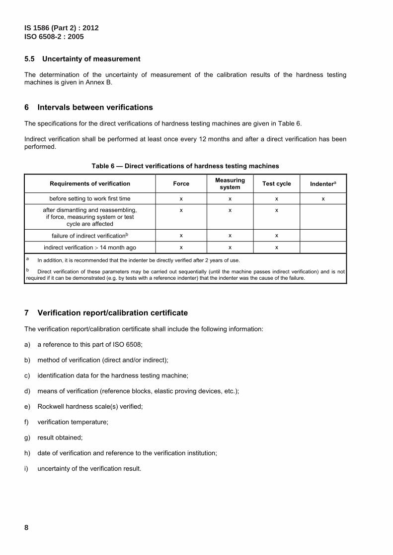
5.5 Uncertainty of measurement
The determination of the uncertainty of measurement of the calibration results of the hardness testing machines is given in Annex B.
6 Intervals between verifications
The specifications for the direct verifications of hardness testing machines are given in Table 6.
Indirect verification shall be performed at least once every 12 months and after a direct verification has been performed.
Table 6 — Direct verifications of hardness testing machines
Requirements of verification Force Measuring system Test cycle Indentera
before setting to work first time x x x x
after dismantling and reassembling, if force, measuring system or test
cycle are affected
x x x
failure of indirect verificationb x x x
indirect verification > 14 month ago x x x
a In addition, it is recommended that the indenter be directly verified after 2 years of use.
b Direct verification of these parameters may be carried out sequentially (until the machine passes indirect verification) and is not required if it can be demonstrated (e.g. by tests with a reference indenter) that the indenter was the cause of the failure.
7 Verification report/calibration certificate
The verification report/calibration certificate shall include the following information:
a) a reference to this part of ISO 6508;
b) method of verification (direct and/or indirect);
c) identification data for the hardness testing machine;
d) means of verification (reference blocks, elastic proving devices, etc.);
e) Rockwell hardness scale(s) verified;
f) verification temperature;
g) result obtained;
h) date of verification and reference to the verification institution;
i) uncertainty of the verification result.
IS 1586 (Part 2) : 2012ISO 6508-2 : 2005
8

Annex A (normative)
Repeatability of testing machines
The permissible repeatability of testing machines is presented graphically in Figures A.1 and A.2.
Key
X Rockwell hardness Y repeatability of testing machines
Figure A.1 — Rockwell hardness (scales A, B, C, D, E, F, G, H and K)
IS 1586 (Part 2) : 2012ISO 6508-2 : 2005
9

Key
X Rockwell hardness Y repeatability of testing machines
Figure A.2 — Rockwell superficial hardness (scales N and T)
IS 1586 (Part 2) : 2012ISO 6508-2 : 2005
10

Annex B (informative)
Uncertainty of measurement of the calibration results of
the hardness testing machine
B.1 Direct calibration of the hardness testing machine
B.1.1 Calibration of the test force
The combined relative standard uncertainty of the test force calibration is calculated according to the following equation:
2 2F FRS FHTMu u u= + (B.1)
with
uFRS is the relative uncertainty of measurement of the force transducer (from calibration certificate);
uFHTM is the relative standard uncertainty of the test force generated by the hardness testing machine.
The uncertainty of measurement of the reference instrument, force transducer, is indicated in the corresponding calibration certificate. The influence quantities, like
⎯ temperature dependence,
⎯ long-term stability, and
⎯ interpolation deviation,
should be considered for critical applications. Depending on the design of the force transducer, the rotational position of the transducer related to the indenter axis of the hardness testing machine should be considered.
NOTE The metrological chain necessary to define and disseminate hardness scales is shown in Figure G.1 in ISO 6508-1:2005.
For example
Uncertainty of measurement of the force transducer (from calibration certificate): UFRS = 0,12 % (k = 2)
Calibration value of the force transducer FRS = 1471,0 N
IS 1586 (Part 2) : 2012ISO 6508-2 : 2005
11

Table B.1 — Results of the test force calibration
Number of height position for test force
calibration
Series 1
F1
N
Series 2
F2
N
Series 3
F3
N
Mean value
F
N
Relative deviation
∆Frel
%
Relative standard
measurement uncertainty
uFHTM
%
1 1 471,5 1 471,9 1 471,7 1 471,7 0,05 0,008
2 1 472,1 1 472,3 1 472,7 1 472,3 0,09 0,012
3 1 472,2 1 473,5 1 471,3 1 472,3 0,09 0,043
where
RSrel
F FF
F−
∆ = (B.2)
FFHTM
1 , ( 3)isu n
nF= ⋅ = (B.3)
sFi is the standard deviation of the test-force indication values in the i-th height position.
In Table B.2, the maximum value of uFHTM from Table B.1 is used.
Table B.2 — Calculation of the uncertainty of measurement of the test force
Quantity
Xi
Estimated value
xi
Relative limit values
ai
Distribution type
Relative standard
measurement uncertainty
u(xi)
Sensitivity coefficient
ci
Relative uncertainty contribution
ui(H)
uFRS 1 471,0 N Normal 6,0 × 10⁻⁴ 1 6,0 × 10⁻⁴
uFHTM 1 471,0 N Normal 4,3 × 10⁻⁴ 1 4,3 × 10⁻⁴
Relative combined standard uncertainty uF 7,4 × 10⁻⁴
Relative expanded uncertainty of measurement UF (k = 2) 1,5 × 10⁻³
Table B.3 — Calculation of the maximum relative deviation of the test force including the uncertainty of measurement of the reference instrument
Relative deviation of test force
∆Frel
%
Expanded relative uncertainty of test force
UF
%
Max. relative deviation of test force including measurement uncertainty
of reference instrument
∆Fmax
%
0,09 0,15 0,24
IS 1586 (Part 2) : 2012ISO 6508-2 : 2005
12

In Table B.3, ∆Fmax is calculated as follows:
max rel FF F U∆ = ∆ + (B.4)
The result of the example means that the deviation of the test force, including the uncertainty of measurement of the reference instrument specified in 4.2 amounting to ± 1,0 %, is complied with.
B.1.2 Depth-measuring system
The combined relative standard uncertainty of the reference instrument for the depth-measuring system is calculated as follows:
2 2 2L LRS ms LHTMu u u u= + + (B.5)
where
uLRS is the relative uncertainty of measurement of the depth calibration device (reference standard) from the calibration certificate for k = 1;
ums is the relative uncertainty of measurement due to the resolution of the measuring system;
uLHTM is the relative standard uncertainty of measurement of the hardness testing machine.
The uncertainty of measurement of the reference instrument for the depth-measuring system, the depth calibration device, is indicated in the corresponding calibration certificate. The influence quantities, for example
⎯ temperature dependence,
⎯ long-term stability, and
⎯ interpolation deviation,
do not exert an essential influence on the uncertainty of measurement of the depth calibration device.
For example:
Uncertainty of measurement of depth calibration system: uLRS = 0,000 2 mm (k = 2)
Resolution of the depth-measuring system δms = 0,5 µm
Table B.4 — Results of the calibration of the depth-measuring system
Rated value of the depth-measuring system
LRS
mm
Series 1
L1
mm
Series 2
L2
mm
Series 3
L3
mm
Mean value
L
mm
Relative deviation
∆Lrel
%
Relative standard
measurementuncertainty
uLHTM
%
0,060 0,060 3 0,060 2 0,060 0 0,060 2 0,33 0,15
0,080 0,080 5 0,080 3 0,080 2 0,080 3 0,38 0,11
0,100 0,100 7 0,100 2 0,100 3 0,100 4 0,40 0,15
0,120 0,120 3 0,120 5 0,120 1 0,120 3 0,25 0,10
0,140 0,140 5 0,140 6 0,140 3 0,140 5 0,33 0,06
0,160 0,160 6 0,160 3 0,160 2 0,160 4 0,23 0,07
IS 1586 (Part 2) : 2012ISO 6508-2 : 2005
13

In Table B.4:
LLHTM
1 , ( 3)isu n
nL= ⋅ = (B.6)
RSrel
RS
L LL
L−
∆ = (B.7)
sLi is the standard deviation of the length indication values for the i-th indication value of the object micrometer.
Table B.5 — Calculation of the uncertainty of measurement of the measuring system
Quantity
Xi
Estimated value
xi
Limit value
ai
Distribution type
Relative standard
measurement uncertainty
u(xi)
Sensitivity coefficient
ci
Uncertainty contribution
ui(H)
uLRS 0 mm 1,0 × 10⁻⁴ mm Normal 1,0 × 10⁻⁴ 1 1,0 × 10⁻⁴
ums 0 mm 0,5 × 10⁻⁴ mm Rectangular 1,8 × 10⁻⁴ 1 1,8 × 10⁻⁴
uLHTM 0,06 mm 0,15 % Normal 9,6 × 10⁻⁴ 1 9,6 × 10⁻⁴
Relative combined uncertainty of measurement uL, (related to 0,16 mm), % 0,098
Relative expanded uncertainty of measurement UL (k = 2), % 0,20
Table B.6 — Calculation of the maximum relative deviation of the measuring system including the uncertainty of measurement of the length reference instrument
Test length
LRS
mm
Relative deviation of the measuring system
∆Lrel
%
Expanded relative uncertainty of measurement
UL
%
Max. relative deviation of measuring system
including measurement uncertainty of length reference instrument
∆Lmax
%
0,16 mm 0,33 0,20 0,53
In Table B.6:
max rel LL L U∆ = ∆ + (B.8)
The result of the example means that the deviation of the measuring system, including the uncertainty of measurement of the length reference instrument specified in 4.4 amounting to ± 1,0 µm (LRS × ∆Lmax = 0,16 mm × 0,57 % = 0,000 91 mm), is complied with.
B.1.3 Verification of the indenter
The indenter, consisting of indenter tip and holder, cannot be verified respectively calibrated, in-site. A valid calibration certificate of an accredited calibration laboratory shall exist which confirms the geometrical deviations of the indenter (see 4.3).
IS 1586 (Part 2) : 2012ISO 6508-2 : 2005
14
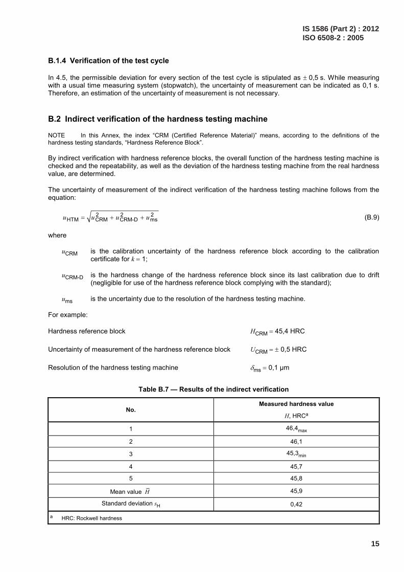
B.1.4 Verification of the test cycle
In 4.5, the permissible deviation for every section of the test cycle is stipulated as ± 0,5 s. While measuring with a usual time measuring system (stopwatch), the uncertainty of measurement can be indicated as 0,1 s. Therefore, an estimation of the uncertainty of measurement is not necessary.
B.2 Indirect verification of the hardness testing machine
NOTE In this Annex, the index “CRM (Certified Reference Material)” means, according to the definitions of the hardness testing standards, “Hardness Reference Block”.
By indirect verification with hardness reference blocks, the overall function of the hardness testing machine is checked and the repeatability, as well as the deviation of the hardness testing machine from the real hardness value, are determined.
The uncertainty of measurement of the indirect verification of the hardness testing machine follows from the equation:
2 2 2HTM CRM CRM-D msu u u u= + + (B.9)
where
uCRM is the calibration uncertainty of the hardness reference block according to the calibration certificate for k = 1;
uCRM-D is the hardness change of the hardness reference block since its last calibration due to drift (negligible for use of the hardness reference block complying with the standard);
ums is the uncertainty due to the resolution of the hardness testing machine.
For example:
Hardness reference block HCRM = 45,4 HRC
Uncertainty of measurement of the hardness reference block UCRM = ± 0,5 HRC
Resolution of the hardness testing machine δms = 0,1 µm
Table B.7 — Results of the indirect verification
No. Measured hardness value
H, HRCa
1 46,4max
2 46,1
3 45,3min
4 45,7
5 45,8
Mean value H 45,9
Standard deviation sH 0,42
a HRC: Rockwell hardness
IS 1586 (Part 2) : 2012ISO 6508-2 : 2005
15

In Table B.7:
CRMb H H= − (B.10)
45,9 45,4 0,5 HRCb = − =
HH
t su
n⋅
= (B.11)
For t = 1,14, n = 5 and sH = 0,42 HRC follows:
uH = 0,21 HRC
B.3 Budget of uncertainty of measurement
Table B.8 — Budget of uncertainty of measurement
Quantity
Xi
Estimated value
xi
Standard uncertainty of measurement
u(xi)
Distribution type
Sensitivity coefficient
ci
Uncertainty contribution
ui(H)
uCRM 45,4 HRC 0,25 HRC Normal 1,0 0,25 HRC
ums 0 HRC 0,029HRC Rectangular 1,0 0,029 HRC
UH 0 HRC 0,21 HRC Normal 1,0 0,21 HRC
uCRM-D 0 HRC 0 HRC Triangular 1,0 0 HRC
Combined uncertainty of measurement, uHTM 0,33 HRC
Expanded uncertainty of measurement, UHTM (k = 2) 0,66 HRC
HRC: Rockwell hardness
Table B.9 — Maximum deviation of the hardness testing machine including the uncertainty of measurement
Measured hardness on the hardness testing machine
H
HRC
Expanded uncertainty of measurement
UHTM
HRC
Deviation of the testing machine when calibrating with the reference block
b
HRC
Maximum deviation of the testing machine including
uncertainty of measurement
∆HHTMmax
HRC
45,1 0,66 0,5 1,12
HRC: Rockwell hardness
In Table B.9:
HTMmax HTMH U b∆ = + = 0,7 + 0,5 = 1,2 HRC (B.12)
IS 1586 (Part 2) : 2012ISO 6508-2 : 2005
16

The result of the example above means that the permissible limit deviation of the testing machine, including the uncertainty of measurement of the testing machine specified in Clause 5 amounting to ± 1,5 HRC, is complied with.
IS 1586 (Part 2) : 2012ISO 6508-2 : 2005
17

Bibliography
[1] A. SAWLA: Uncertainty of measurement in the verification and calibration of the force measuring systems of testing machines. Proceedings of the Asia-Pacific symposium on measurement of force, mass and torque (APMF), Tsukuba, Japan, November 2000
[2] A. WEHRSTEDT, I. PATKOVSZKY: News in the field of standardization about verification and calibration of materials testing machines, May 2001, EMPA Academy 2001
[3] W. GABAUER: Manual codes of practice for the determination of uncertainties in mechanical tests on metallic materials, The estimation of uncertainties in hardness measurements, Project No. SMT4-CT97-2165, UNCERT COP 14:2000
[4] T. POLZIN, D. SCHWENK: Method for Uncertainty Determination of Hardness Testing; PC File for Determination, Materialprüfung 44 (2002) 3, pp. 64-71
IS 1586 (Part 2) : 2012ISO 6508-2 : 2005
18

International Standard Corresponding Indian Standard Degree of Equivalence
ISO 6508-3 : 2005 Metallic materials— Rockwell hardness test — Part 3:Calibration of reference blocks(scales A, B, C, D, E, F, G, H, K, N,T)
IS 1586 (Part 3) : 2012 Metallicmaterials — Rockwell hardness test:Part 3 Calibration of reference blocks(scales A, B, C, D, E, F, G, H, K, N,T) (fourth revision)
Identical
For the purpose of deciding whether a particular requirement of this standard is complied with, thefinal value, observed or calculated, expressing the result of a test or analysis, shall be rounded off inaccordance with IS 2 : 1960 ‘Rules for rounding off numerical values (revised)’. The number ofsignificant places retained in the rounded off value should be the same as that of the specified valuein this standard.
(Continued from second cover)

Bureau of Indian Standards
BIS is a statutory institution established under the Bureau of Indian Standards Act, 1986 to promoteharmonious development of the activities of standardization, marking and quality certification of goodsand attending to connected matters in the country.
Copyright
BIS has the copyright of all its publications. No part of these publications may be reproduced in any formwithout the prior permission in writing of BIS. This does not preclude the free use, in course of imple-menting the standard, of necessary details, such as symbols and sizes, type or grade designations.Enquiries relating to copyright be addressed to the Director (Publications), BIS.
Review of Indian Standards
Amendments are issued to standards as the need arises on the basis of comments. Standards are alsoreviewed periodically; a standard along with amendments is reaffirmed when such review indicates thatno changes are needed; if the review indicates that changes are needed, it is taken up for revision. Usersof Indian Standards should ascertain that they are in possession of the latest amendments or edition byreferring to the latest issue of ‘BIS Catalogue’ and ‘Standards: Monthly Additions’.
This Indian Standard has been developed from Doc No.: MTD 3 (4898).
Amendments Issued Since Publication______________________________________________________________________________________
Amendment No. Date of Issue Text Affected______________________________________________________________________________________
______________________________________________________________________________________
______________________________________________________________________________________
______________________________________________________________________________________
______________________________________________________________________________________
BUREAU OF INDIAN STANDARDSHeadquarters:
Manak Bhavan, 9 Bahadur Shah Zafar Marg, New Delhi 110002Telephones: 2323 0131, 2323 3375, 2323 9402 Website: www.bis.org.in
Regional Offices: Telephones
Central : Manak Bhavan, 9 Bahadur Shah Zafar Marg 2323 7617NEW DELHI 110002 2323 3841
Eastern : 1/14, C.I.T. Scheme VII M, V.I.P. Road, Kankurgachi 2337 8499, 2337 8561KOLKATA 700054 2337 8626, 2337 9120
Northern : SCO 335-336, Sector 34-A, CHANDIGARH 160022 260 3843260 9285
Southern : C.I.T. Campus, IV Cross Road, CHENNAI 600113 2254 1216, 2254 14422254 2519, 2254 2315
Western : Manakalaya, E9 MIDC, Marol, Andheri (East) 2832 9295, 2832 7858MUMBAI 400093 2832 7891, 2832 7892
Branches: AHMEDABAD. BANGALORE. BHOPAL. BHUBANESHWAR. COIMBATORE. DEHRADUN.FARIDABAD. GHAZIABAD. GUWAHATI. HYDERABAD. JAIPUR. KANPUR. LUCKNOW.NAGPUR. PARWANOO. PATNA. PUNE. RAJKOT. THIRUVANATHAPURAM. VISAKHAPATNAM.
Published by BIS, New Delhi
{
{{
{{