Embed Size (px)
Citation preview

Disclosure to Promote the Right To Information
Whereas the Parliament of India has set out to provide a practical regime of right to information for citizens to secure access to information under the control of public authorities, in order to promote transparency and accountability in the working of every public authority, and whereas the attached publication of the Bureau of Indian Standards is of particular interest to the public, particularly disadvantaged communities and those engaged in the pursuit of education and knowledge, the attached public safety standard is made available to promote the timely dissemination of this information in an accurate manner to the public.
इंटरनेट मानक
“!ान $ एक न' भारत का +नम-ण”Satyanarayan Gangaram Pitroda
“Invent a New India Using Knowledge”
“प0रा1 को छोड न' 5 तरफ”Jawaharlal Nehru
“Step Out From the Old to the New”
“जान1 का अ+धकार, जी1 का अ+धकार”Mazdoor Kisan Shakti Sangathan
“The Right to Information, The Right to Live”
“!ान एक ऐसा खजाना > जो कभी च0राया नहB जा सकता है”Bhartṛhari—Nītiśatakam
“Knowledge is such a treasure which cannot be stolen”
“Invent a New India Using Knowledge”
है”ह”ह
IS 15530 (2004): Conveyor Chains, Attachments and Sprockets[MED 6: Continuous Bulk Conveying, Elevating, HoistingAerial Ropeways and Related Equipment]


IS 15530:20041s01977:2000
m%, +hJ-i* ** – mTf&
Indian Standard
CONVEYOR CHAINS, ATTACHMENTS ANDSPROCKETS — SPECIFICATION
ICS 53.040.20
@ BIS 2004
BUREAU OF INDIAN STANDARDSMANAK BHAVAN, 9 BAHADUR SHAH ZAFAR MARG
NEW DELHI 110002
September 2004 Price Group 7

Continuous Bulk Conveying, Elevating, Hoisting, Arial Ropeways and Related Equipment Sectional
Committee, ME 06
NATIONAL FOREWORD
This Indian Standard which is identical with ISO 1977:2000 ‘Conveyor chains, attachments andsprockets’ issued by the International Organization for Standardization (ISO) was adopted by the Bureauof Indian Standards on the recommendations of the Continuous Bulk Conveying, Elevating, Hoisting,Arial Ropeways and Related Equipment Sectional Committee and approval of the Mechanical EngineeringDivision Council.
The text of ISO Standard has been approved as suitable for publication as an Indian Standard withoutdeviations. Certain terminology and conventions are, however, not identical to those used in the IndianStandards. Attention is drawn especially to the following:
a) Wherever the words ‘International Standard’ appear referring to this standard, they shouldbe read as ‘Indian Standard’.
b) Comma (,) has been used as a decimal marker, while in Indian Standards, the current practiceis to use a point (.) as the decimal marker.
CROSS REFERENCE
In this adopted standard, reference appears to the following International Standard for which IndianStandard also exists. The corresponding Indian Standard which is to be substituted in its place is listedbelow along with its degree of equivalence for the edition indicated:
International Standard Corresponding Indian Standard Degree ofEquivalence
ISO 286-2:1988 ISO system of IS 919 (Part 2) :1993 ISO system of limits Identical
limits and fits — Part 2: Tables of and fits: Part 2 Tables of standard tolerances
standard tolerance grades and grades and limit deviations for holes and
limit deviations for holes and shafts (first revision)
shafts
BIS CERTIFICATION MARKING
Details available with the Bureau of Indian Standards.
For the purpose of deciding whether a particular requirement of this standard is complied with, the finalvalue, observed or calculated, expressing the result of a test or analysis, shall be rounded off in accordancewith IS 2 :1960 ‘Rules for rounding off numerical values (revised)’. The number of significant placesretained in the rounded off value should be same as that of the specified value in this standard.

IS 15530:2004ISO 1977:2000
Indian Standard
CONVEYOR CHAINS, ATTACHMENTS ANDSPROCKETS — SPECIFICATION
1 Scope
This International Standard specifies the characteristics of bush, plain and flanged roller chains of both solid andhollow bearing pin types designed for general conveying and mechanical handling duties, together with associatedchain sprockets and attachments. The chain dimensions specified in this International Standard will ensureinterchangeability of complete chains and individual links for repair purposes.
This International Standard is applicable to sprockets with from 6 to 40 teeth. Control criteria for sprocke~s aredefined to ensure correct meshing, operation and transmission of load in use under normal operating conditions.
NOTE Controls do not necessarily determine sprocket design parameters.
Specifications are also given for K attachments and deep plates for use with the conveyor chains conforming to thisinternational Standard.
2 Normative reference
The following normative document contains provisions’which, through reference in this text, constitute provisions ofthis International Standard. For dated references, subsequent amendments to, or revisions of, any of thesepublications do not apply. However, parties to agreements based on this International Standard are encouraged toinvestigate the possibility of applying the most recent edition of the normative document indicated below. Forundated references, the latest edition of the normative document referred to applies. Members of ISO and IECmaintain registers of currently valid International Standards.
ISO 286-2:1988, !S0 system of limits and fits — Part 2: Tables of standard tolerance grades and limit deviations forholes and shafts.
3 Chains
3.1 Nomenclature
The nomenclature of the chains and their component parts is presented in Figure 1.
3.2 Dimensions
Conveyor chain dimensions shall conform to those given in Table 1 or Table 2 (see Figure 2). Both maximum andminimum dimensions are specified to ensure the interchangeability of links made by different chain manufacturers.Although these represent limits for interchangeability, they are not necessarily to be regarded as limits of tolerancefor manufacture.
1
... ...

IS 15530:20041s0 1977:2000
a) Solid-bearing pin chain
b) Hollow-bearing pin chain
1 3
5
@o 0
4
d) Outer link (solid-bearing pins)
7 9
R8 10
f) Connecting link (cotter pin fasteners)
2
c) Inner link
6
eo 0
4
e) Outer link (hollow-bearing pins)
7 9
B8 11
g) Connecting link (nut fastenera)
2

“IS 15530:20041s0 1977:2000
3 12 1
(0 L
13 2
h) Cranked linkdouble (solid-bearing pin)
Key
1
2
3
4
5a
d,d2
d3
d4
h2
b,b2
13 ‘2
i) Cranked linkdouble (hollow-bearing pin)
Roller 6 Bearing pins (hollow)Bush 7 Fixed outer plateInner plate 8 Detachable plateOuter plate 9 Connecting pinsBearing pins (solid) 10 Cotter pin fasteners aThe type of fastener (cotter pin, nut, etc.) is optional.
Figure 1 — Chain parts
P P
c- 3/
/ w/ I
‘“–”– * “+{ .—. _ “=
t+++-.
I
11 Nut fasteners
12 Cranked plate
13 Bearing pin (riveted)
-A!.d2
s 15° max
-1d5
plain roller diameter b3 width between outer plates d6bearing-pin body diameter b4 width over bearing pins d,bush bore b, additional width for joint fasterbush diameter [, cranked link dimensionplate depth Flange roller dimensions:width between inner plates — d5 flange diameterwidth over inner links — bll flange width
NOTE 1 Bearing pins may be of necked design, as shown here, or plain as in Figure 1.
hollow-pin bore
small roller diameter
.
NOTE 2 These illustrations do not define the true form of the chain plates, pins, bushes or rollers.
Figure 2 — Chain dimensions and symbols (see Tab/e 7 and Tab/e 2)
3
- . ..

IS 15530:2004
1s0 1977:2000
Table 1 — Solid pin conveyor chain dimensions and characteristics
I Tensile1s0 I d,
strengthchain
‘wn28 I 28 ] 30
~80 I 80 I 50
a=dl12 112 60
ti160 160 70
b4224 224 85
W315 315 100
M450 450 120
b1630 630 140
M900 ) 900 I 170
Pitcha bcP
,mm
40 50 63 80 100 125 160 200 250 315 400 500 630 800 1000
x
x
x
x
x
x
x
x
a Pitch, p, is a theoretical reference dimension used in the calculation of chain lengths and sprocket dimensions, and is notintended for use in the inspection of individual links.
b Those pitches indicated by an X are for bush and small roller chains only.
c Those pitches within the shaded area are the preferred pitches.
d Thecranked link dimension/l also determines themaximum plate length andthelimit of thepath ofatiiculation taking
minimum play into account.
Table 2 — Hollow pin conveyer chain dimensions and characteristics
Tensile1s0 d, Pitcha b
strengthd2 d3 d4 112
chainp
mm(b::ic) kN
mm mm
max. 63 80 100 125 160 200 250 315 400 500 max. min. max max.
klC28 28 36 13 13,1 17,5 26
klC56 56 50 15,5 15,6 21,0 36
ticl 12 112 70 22 22,2 29,0 51
WC224 224 100 31 31,2 41,0 72
a Pitch, p, is a theoretical reference dimension used in the calculation of chain lengths and sprocket dimensions, and is notintended for use in the inspection of individual links.
b Those pitches within the shaded area are the preferred pitches.
c The cranked link dimension /1 also determines the maximum plate length and the limit of the path of articulation taking
minimum play into account.
4

IS 15530:20041s0 1977:2000
Tablel (continue@
dz d~ d4 hz bl bz b3 b4 %
mm
max. min. max. max. min. max. min. max. max.
6 6,1 9 19 16 22 22,2 35 7
7 7,1 10 21 18 25 25,2 40 8
8,5 8,6 12,5 26 20 26 28,3 45 9
10 10,1 15 31 24 33 33,3 52 10
12 12,1 18 36 28 39 39,4 62 12
15 15,1 21 41 32 45 45,5 73 14
18 18,1 25 51 37 52 52,5 85 16
21 21,2 30 62 43 60 60,6 98 18
25 25,2 36 72 48 70 70,7 112 21
30, 30,2 42 82 56 82 82,8 135 25
36 36,2 50 103 66 96 97 154 30
44 44,2 60 123 76 112 113 180 37
MeesuringForce
kN
0,4
0,56
0,8
1,12
1,6
2,24
3,2
4,5
6,3
9
12,5
18
mmm
min. max. max. max.
12,5 32 3,5 12,51 r
14 36 4 15
17 42 4,5 18
20,5 50 5 21
23,5 60 6 25
27,5 70 7 30
+-K-F++471120112150
Table 2 (continue@
b, b~ h?J b4 b,Measuring
Forcel,C d5 bl 1 d6 d,
mmkN
mm
min. max. min. max. max. min. max. max. min. max.
20 28 28,3 42 10 0,56 17,0 42 4,5 8,2 25
24 33 33,3 48 13 1,12 23,5 60 5 10,2 30
32 45 45,5 67 19 2,24 34,0 85 7 14,3 42
43 60 60,6 90 24 4,50 47,0 120 10 20,3 60
!5

IS 15530:20041s0 1977:2000
3.3 Tensile testing
The test length shall have a minimum of three free pitches. The ends shall be attached to the testing-machineshackles by a pin through the plate holes or the bushes. The shackles shall be designed so as to allow universalmovement. The actual test method shall be left to the manufacturer’s discretion. Tests in which failures occuradjacent to the shackles shall be disregarded.
3.4 Length accuracy
3.4.1 General
When measured in accordance with the requirements given in 3.4.2, 3.4.3 and 3.4.4, the finished chain shall be
accurate to within ~’zs”’” of the nominal chain length.
NOTE Chains that work in parallel can be matched by agreement between the purchaser and manufacturer.
3.4.2 Standard test-measurement length
The length of chain for measurement shall be that nearest to 3000 mm with an odd number of pitches, terminatingwith inner links at each end.
3.4.3 support
The chain, in unlubricated condition, shall be supported throughout its entire length.
3.4.4 Measuring force
A force equal to 1/50 of the appropriate tensile strength given in Table 1 or Table 2 shall be applied.
3.5 Cranked links
In order to obtain an odd number of pitches in an endless chain, a cranked link is used [see Figure 1 h) and 1 i)].The cranked link dimension of a chain shall correspond to its respective /1 as given in Table 1 or Table 2 and as
appropriate.
3.6 Designation
The designation numbers for conveyor chains are based on the ISO numbers givennumbers are derived from the minimum tensile strength (in kilonewtons) and haveindicate a solid-bearing pin chain, and MC, to indicate a hollow-bearing pin chain.
EXAMPLE M80 signifies a solid-bearing pin chain of 80 kN tensile strength.
MC224 signifies a hollow-bearing pin chain of 224 kN tensile strength.
in Table 1 and Table 2. Thesebeen given the prefixes M, to
The addition of the letter B, F, P or S indicates type: bush, flanged roller, plain or small roller, respectively. Theaddition of further digits indicates the pitch in millimetres.
EXAMPLE MC224 chain with flanged roller and pitch of 200 mm:
MC224-F-200
3.7 Marking
The chains shall be marked with the manufacturer’s name or trademark, and should be marked with the respectiveISO chain number given in Table 1 or Table 2.
6
.... . .
IS 15530:20041s0 1977:2000
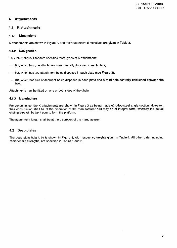
4 Attachments
4.1 K attachments
4.1.1 Dimensions
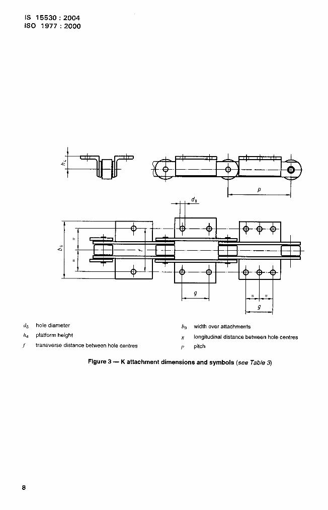
K attachments are shown in Figure 3, and their respective dimensions are given in Table 3.
4.1.2 Designation
This International Standard specifies three types of K attachment:
— KI, which has one attachment hole centrally disposed in each plate;
. K2, which has two attachment holes disposed in each plate (see Figure 3);
. K3, which has two attachment holes disposed in each plate and a third hole centrally positioned between thetwo.
Attachments may be fitted on one or both sides of the chain.
4.1.3 Manufacture
For convenience, the K attachments are shown in Figure 3 as being made of rolled-steel angle section. However,their construction shall be at the discretion of the manufacturer and may be of integral form, whereby the actualchain plates will be bent over to form the platform.
The attachment length shall be at the discretion of the manufacturer.
4.2 Deep plates
The deep-plate height, hIj is shown in Figure 4, with respective heights given in Table 4. All other data, includingchain tensile strengths, are specified in Tables 1 and 2.
7
IS 15530:20041s0 1977:2000
I D I
d8
T
A
ALII ‘1
m ! !
-a I I—.—%I,!1 m
{T
A / 1-
1 “< 1-
I-4
(& hole diameter b9 width over attachments
/Z4 platform height~ longitudinal distance between hole centres
/transverse distance between hole centres P pitch
Figure 3 — K attachment dimensions and symbols (see Tab/e 3)
8
.... . .
IS 15530:20041s0 1977:2000
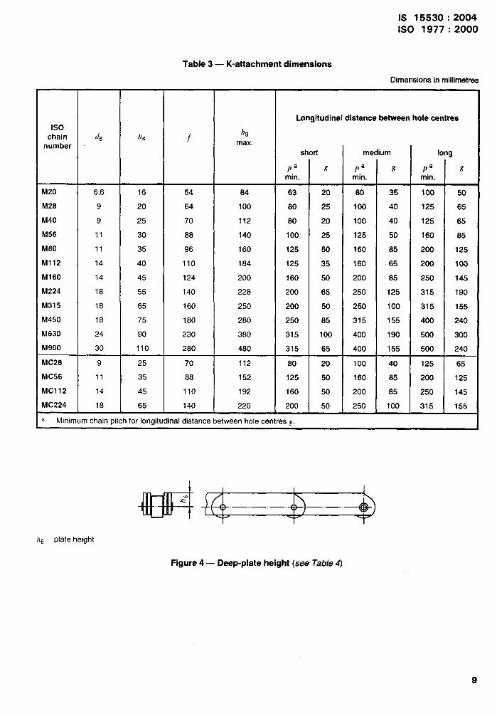
Table 3 — K-attachment dimensions
Dimensions in millimetres
Longitudinal distanca between hole centres1s0
chain (IB /14 fbg
number max.
short medium long
Pa t? Pa g Pa gmin. min. min.
M20 6,6 16 54 84 63 20 80 35 100 50
M28 9 20 64 100 80 25 100 40 125 65
M40 9 25 70 112 80 20 100 40 125 65
M56 11 30 88 140 100 25 125 50 160 85
M80 11 35 96 160 125 50 160 85 200 125
M112 14 40 110 184 125 35 160 65 200 100
M160 14 45 124 200 160 50 200 85 250 145
M224 18 55 140 228 200 65 250 125 315 190
M315 18 65 160 250 200 50 250 100 315 155
M450 18 75 180 280 250 85 315 155 400 240
M630 24 90 230 380 315 100 400 190 500 300
M900 30 110 280 480 315 65 400 155 500 240
MC28 9 25 70 112 80 20 100 40 125 65
MC56 11 35 88 152 125 50 160 85 200 125
MC112 14 45 110 192 160 50 200 85 250 145
MC224 18 65 140 220 200 50 250 100 315 155
3 Minimum chain pitch for longitudinal distance between hole centres g.
I I
/16 plate height
,-.,,
Figure 4 — Deep-plate height (see Tab/e 4)
9

IS 15530:20041s0 1977:2000
5
5.1
Table 4 — Deep plate heights
Dimensions in millimetres
ISO chain number h6
M20 16
M28 20
M40 22,5
M56 30
M80 32,5
M112 40
M160 45
M224 60
M315 65
M450 80
M630 90
M900 120
MC28 22,5
MC56 32,5
MC112 45
MC224 65
NOTE All other data, including those relating to tensile strength, areas those given for the basic chain plates in clause 3.
Diametral dimensions
5.1.1 General
The sprocket diametral dimensions are shown in Figure 5, and specified in 5.1.2 to 5.1.6.
5.1.2 Pitch circle diameter (d)
d=~sin 180°
z
The unitary dimensions of the normal range of teeth are given in Annex A.
5.1.3 Tip diameter (da)
damax=d+dl
The minimum tip diameter shall ensure a tooth working face according to 5.2.2.
. *, .,.-

IS 15530:2004ISO 1977:2000
--#-l--
b=
bf
bg
d
da
df
d9
a
b
c
e
tooth side relief dR
tooth width d,
relieved tooth width minimum dz
pitch circle diameter ha
tip diameter MR
root diameterP
absolute maximum shroud diameter ra
Even numbers of teeth d
odd numbers of teeth e
Roller seating retief f
// ,./’. .Hv
measuring-pin diameter
plain roller diameter
bearing-pin body diameter
tooth height above root diameter
measurement over measuring pina
chordal pitch (= chain pitch)
shroud radius
G roller seating radius
rx minimum tooth side radius
s pitch line clearance
z number of teeth
a roller seating angle
Pitch polygon
Tooth flank
Depending on the type of roller, dl maybe replaced with d4 or d7.
NOTE For other than roller chains, replace the term roller by the term bush.
Figure 5 — Sprocket parts and dimensions
11

IS 15530:2004
1s0 1977:2000
5.1.4 Measuring-pin diameter (dR)
As appropriate, dR = d,, dq or d7, subject to tolerance hl 1, as specified in ISO 286-2.
5.1.5 Rootdiameter(df)
As appropriate, df max. = d - dl or d - d4 or d - d7.
The minimum root diameter shall be selected by the manufacturer to provide good chain operation.
5.1.6 Measurement over t’fIeaSUring pins (kfR)
For even numbers of teeth, measurement over measuring pins, ~R = d + dR min., and measurement shall be made
over the appropriate pins inserted in diametrically opposed tooth spaces.
For odd numbers of teeth, kfR = d cos (900/z ) + dR min., and f?IeaSUreI?Ient shall be made over pinS inserted in the
tooth spaces most nearly diametrically opposite.
During measurement, the pins shall always be in contact with the root diameter of the corresponding teeth.
5.2 Sprocket tooth gap form
5.2.1 General
The tooth gap shall be defined according to the criteria of 5.2.2 to 5.2.7 (see Figure 5).
5.2.2 Working Face
The working face, the functional part of the tooth form; is the area between the lines of contact of two rollers, withthe centreiine of the one roller lying on the pitch circle, and that of the other on a circle of diameter equal to:
p+0,25d2~in1800
z
That is, except when this is reduced owing to the limitation imposed on the tooth height, as given in 5.2.4.
The working face may be straight or convex.
5.2.3 Pressure angle
The pressure angle is the angle between the pitch line of the chain link and the line perpendicular to the workingface at the point of roller contact. The pressure angle at any point on the working face shall be in accordance withTable 5.
5.2.4 Tooth height above root diameter (ha)
~ =da-dfa 2
,-
When slats are attached to the K-attachment platforms and the starts bridge the chain link, the tip of the tooth shallnot project above the chord of the pitch circle by any more than 0,8 h4, where h4 is the platform height of the
attachment according to Table 3.
12
-..+ .... .
IS 15530:2004ISO 1977:2000
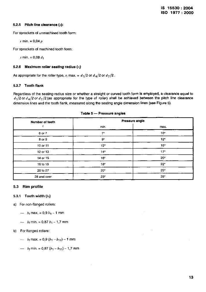
5.2.5 Pitch iineclearance (s):
For sprockets of unmachined tooth form:
s min. = 0,04p
For sprockets of machined tooth form:
s min. = 0,08 dl
5.2.6 Maximum roller seating radius (q)
As appropriate for the roller type, q max. = dl/2 or d4/2 or d7/2.
5.2.7 Tooth flank
Regardless of the seating-radius size or whether a straight or curved tooth form is employed, a clearance equal todl /2 or d4/2 or d7/2 (as appropriate for the type of roller) shall be achieved between the pitch line clearance
dimension lines and the tooth flank, measured along the seating angle dimension lines (see Figure 5).
Table 5 — Pressure angles
Number of teeth Pressure angle~ min. max.
6or7 7° 1o“
8or9 9° 12“
10orll 12° 15“
12 or’13 14“ 17“
140r15 16° 20”
16to19 18° 22”
20 to 27 20° 25°
28 and over 23° 28°
5.3 Rim profile
5.3.1 Tooth width (bf)
a) For non-flanged rollers:
— bf max. = 0,9 l-q -1 mm
— bf min. = 0,87 bl – 1,7 mm
b) For flanged rollers:
. bf max. = 0,9 (bl –bll) – 1mm
— bfmin. = 0,87 (bl –bll)- 1,7 mm
13
‘,’?.*-
IS 15530:20041S0 1977:2000
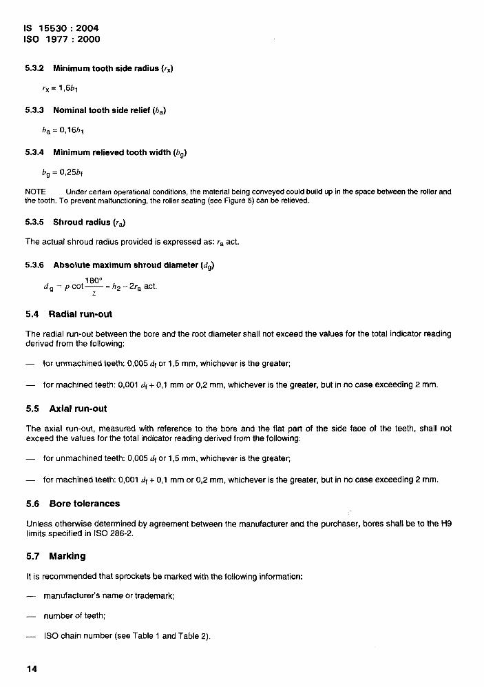
5.3.2 Minimum tooth side radius (rx)
rx= l,6b1
5.3.3 Nominal tooth side relief (ba)
ba = 0,16bl
5.3.4 Minimum relieved tooth width (bg)
b~ = 0,25bf
NOTE Under certain operational conditions, the material being conveyed could build up in the space between the roller andthe tooth. To prevent malfunctioning, the roller seating (see Figure 5) can be relieved.
5.3.5 Shroud radius (ra)
The actual shroud radius provided is expressed as: ra act.
5.3.6 Absolute maximum shroud diameter (dg)
180°d~ = pcot— - h2 - 2ra act.
z
5.4 Radial run-out
The radial run-out between the bore and the root diameter shall not exceed the values for the total indicator readingderived from the following:
— for unmachined teeth: 0,005 df or 1,5 mm, whichever is the greaten
— for machined teeth: 0,001 df + 0,1 mm or 0,2 mm, whichever is the greater, but in no case exceeding 2 mm.
5.5 Axial run-out
The axial run-out, measured with reference to the bore and the flat part of the side face of the teeth, shall notexceed the values for the total indicator reading derived from the following:
— for unmachined teeth: 0,005 df or 1,5 mm, whichever is the greateL
— for machined teeth: 0,001 df + 0,1 mm or 0,2 mm, whichever is the greater, but in ho case exceeding 2 mm.
5.6 Bore tolerances
Unless otherwise determined by agreement between the manufacturer and the purchaser, bores shall be to the H9limits specified in ISO 286-2.
5.7 Marking
Itis recommended that sprockets be marked with the following information:
— manufacturer’s name or trademark;
— number of teeth;
. ISO chain number (see Table 1 and Table 2).
14

IS 15530:20041s0 1977:2000
Annex A(normative)
Pitch-circle diameters
Table A.1 specifies sprocket pitch-circle diameters suitable for a chain of unit pitch. Pitch-circle diameters suitablefor a chain of any other pitch are directly proportional to that particular pitch.
Table A.1 — Pitch-circle diameters
Dimensions in millimetres
Number of teeth Pitch-circle Number of teeth Pitch-circle Number of teeth Pitch-circlez diameter, d, z diameter, d, z diameter, d,
for unit pitcha for unit pitcha for unit pitcha
6 2,0000 18 5,7588 30 9,5668
6X 2,1519 18Y2 5,9171 30% 9,7256
7 2,3048 19 6,0755 31 9,8845
7% 2,4586 19% 6,2340 31% 10,0434
8 2,6131 20 6,3925 32 10,2023
8% 2,7682 20% 6,5509 32?4 10,3612
9 2,9238 21 6,7095 33 10,5201
9% 3,0798 21% 6,8681 33% 10,6790
10 3,2361 22 7,0266 34 10,8380
1OY2 3,3927 22% 7,1853 34% 10,9969
11 3,5494 23 7,3439 35 11,1558
11% 3,7065 23% 7,5026 35% 11,3148
12 3,8637 24 7,6613 36 11,4737
12% 4,0211 24% 7,8200 36% 11,6327
13 4,1786 25 7,9787 37 11,7916
13!4 4,3362 25% 8,1375 37% 11,9506
14 4,4940 26 8,2962 38 12,1095
14yz 4,6518 26% 8,4550 38% 12,2685
15 4,8097 27 8,6138 39 12,4275
15% 4,9677 27% 8,7726 39% 12,5865
16 5,1258 28 8,9314 40 12,7455
16% 5,2840 28% 9,0902
17 5,4422 29 9,2491
17% 5,6005 29% 9,4080
‘ The actual pitch circle diameter can be obtained by multiplying this number by the pitch of the chain.
15

Bureau of Indian Standards
BIS is a statutory institution established under the Bureau of Mkm Standards Act, 1986 to promote
harmonious development of the activities of standardization, marking and quality certification of
goods and attending to connected matters in the country.
Copyright
BIS has the copyright of all its publications. No part of these publications may be reproduced in any
form without the prior permission in writing of BIS. This does not preclude the free use, in the course
of implementing the standard, of necessary details, such as symbols and sizes, type or grade
designations. Enquiries relating to copyright be addressed to the Director (Publication), 61S.
Review of Indian Standards
Amendments are issued to standards as the need arises on the basis of comments. Standards are also
reviewed periodically; a standard along with amendments is reaffirmed when such review indicates that
no changes are needed; if the review indicates that changes are needed, it is taken up for revision.
Users of Indian Standards should ascertain that they are in possession of the latest amendments or
edition by referring to the latest issue of ‘BIS Catalogue’ and ‘Standards: Monthly Additions’.
This Indian Standard has been developed from Dot: No. MED 06 (0737).
Amendments Issued Since Publication
Amend No. Date of Issue Text Affected
BUREAU OF INDIAN STANDARDS
Headquarters:
Manak Bhavan, 9 Bahadur Shah Zafar Marg, New Delhi 110002Telephones 23230131,23233375,2323 9402 website: www.bis.org.in
Regional Offices: Telephones
Central :
Eastern :
Northern :
Southern :
Western :
Branches:
Manak Bhavan, 9 Bahadur Shah Zafar Marg{
23237617NEW DELHI 110002 23233841
1/1 4 C.I.T. Scheme Vll M, V.I.P. Road, Kankurgachi{
23378499,23378561KOLKATA 700054 23378626,23379120
SCO 335-336, Sector 34-A, CHANDIGARH 160022{
26038432609285
C.I.T. Campus, IV Cross Road, CHENNAI 600113{
22541216,2254144222542519,22542315
Manakalaya, E9 MlDC, Marol, Andheri (East){
28329295,28327858MUMBAI 400093 28327891,28327892
AHMEDABAD. BANGALORE. BHOPAL. BHUBANESHWAR. COIMBATORE. FARIDABAD.
GHAZIABAD. GUWAHATI. HYDERABAD. JAIPUR. KANPUR, LUCKNOW. NAGPUR.
NALAGARH. PATNA. PUNE. RAJKOT. THIRUVANANTHAPURAM. VISAKHAPATNAM.
Printed at Simco Printing Press, Delhi