Embed Size (px)
Citation preview

Disclosure to Promote the Right To Information
Whereas the Parliament of India has set out to provide a practical regime of right to information for citizens to secure access to information under the control of public authorities, in order to promote transparency and accountability in the working of every public authority, and whereas the attached publication of the Bureau of Indian Standards is of particular interest to the public, particularly disadvantaged communities and those engaged in the pursuit of education and knowledge, the attached public safety standard is made available to promote the timely dissemination of this information in an accurate manner to the public.
इंटरनेट मानक
“!ान $ एक न' भारत का +नम-ण”Satyanarayan Gangaram Pitroda
“Invent a New India Using Knowledge”
“प0रा1 को छोड न' 5 तरफ”Jawaharlal Nehru
“Step Out From the Old to the New”
“जान1 का अ+धकार, जी1 का अ+धकार”Mazdoor Kisan Shakti Sangathan
“The Right to Information, The Right to Live”
“!ान एक ऐसा खजाना > जो कभी च0राया नहB जा सकता है”Bhartṛhari—Nītiśatakam
“Knowledge is such a treasure which cannot be stolen”
“Invent a New India Using Knowledge”
है”ह”ह
IS 13612-1 (1993): Modular co-ordination for normalbrickwork - Recommendations, Part 1: Burnt clay bricks [CED51: Planning, Housing and pre-fabricated construction]


IS 13612 ( Part 1) : 1993 I
md-h wm
Indian Standard
MODULARCO-ORDINATIONFORNORMAL BRICKWORK- RECOMMENDATIONS
PART 1 BURNT CLAY BRICKS
UDC 721.013 : 006.78 : 666.71
0 BIS 1993
BUREAU OF INDIAN STANDARDS MANAK BHAVAN, 9 BAHADUR SHAH ZAFAR MARG .
NEW DELHI 110002
Febraury 1993 Price Group 7
Planning, Bye-laws and Dimensional Co-ordination Sectional Committee, CED 10
FOREWORD
This Indian Standard was adopted by the Bureau of Indian Standards, after the draft finalized by the Planning, Bye-laws and Dimensional Co-ordination Sectional Committee had been approved by the Civil Engineering Division Council.
Bricks are one of the most common building components for a variety of uses in the construction industry. These are manufactured from locally available clays. In India, non-modular bricks are avail- able in different dimensions.
The metric system became effective in early sixties in the country through legislation. With this legislation, the Bureau recommended the use of modular bricks in place of non-modular burnt clay building bricks. The Bureau of Indian Standards has brought out a number of standards on dimensions, quality, strength, classifications, grading and methods of test for metric bricks. ZS 1077 : 1986 and IS 2180 : 1985 suggest two sizes of common building burnt clay bricks, namely 200 mm x 100 mm x 100 mm and 200 mm x 100 mm x 50 mm. The bond arrangements are similar to the well known bonds, but are based on third bonding; that is, overlap is one third of the brick and not one fourth as in the case of non-modular brick.
The adoption of modular co-ordination system in construction industry has been advocated by many national organizations. A number of committees have reported the advantages of metric/modular bricks and suggested incentive measures for metric-brick manufacturers. In spite of these efforts, nearly 50,000 million non-modular size bricks continue to be manufactured in this country.
Designers are very apprehensive, because of non-availability of modular size bricks, to adopt modular co-ordination in a project. The manufacturers have some reservation to produce modular bricks since they claim to face manufacturing and marketing problems. Inspite of best efforts and encouragement given, the production of modular bricks remained insignificant. As a result, modular co-ordination and metric system have not yet been able to replace the non-modular brick in the country.
This standard has been formulated with a view to accelerating the adoption of modular co-ordination in the construction industry using the available non-modular size of bricks for a project by the designers. It is intended to be a working reference for the dimensional control of brickwork.
This standard has been formulated with considerable assistance from the National Building Organization, New Delhi.
In formulation of this standard due weightage has been given to international co-ordination among the standards and practices prevailing in different countries in addition to relating it to the practices in the field in this country. This has been met by deriving assistance from the following documents:
a) Industrialised Building and Modular Design: Henrik Nissen. Cement and Concrete Association, London ( 1972 ).
b) DS 1048-1966 Normal Brickwork and Modular Co-ordination. Dansk Standardiseringarad.
For the purpose of deciding whether a particular requirement of this standard is complied with, the final value, observed or calculated, expressing the result of a test or analysis, shall be rounded off in accordance with IS 2 : 1960 ‘Rules for rounding off numerical values ( revised )‘. The number of significant places retained in the rounded off value should be the same as that of the specified value in this standard.
Is 13612 ( Part- 1) : 1993
Indian Standard
MODULARCO-ORDINATIONFORNORMAL BRICKWORK- RECOMMENDATIONS
PART 1 BURNT CLAY BRICKS
1 SCOPE
1.1 This standard deals with the application of modular co-ordination in brickwork using modular and non-modular bricks.
1.2 This standard covers recommendations for achieving modular co-ordination in brickwork using modular and non-modular brick sizes, and preferred horizontal and vertical controlling dimensions in all types of buildings. This is intended to be a working reference for the dimensional control of all types of brickwork.
2 REFERENCES
The Indian Standards listed in Annex A are necessary adjuncts to this standard.
3 TERMINOLOGY
For the purpose of this standard, the definitions given in IS 4993 : 1983, TS 7921 : 1987 and IS 7922 : 1987 shall apply.
4 GENERAL CONCEPT
4.1 Dimensional co-ordination amongst different building components is very important to reduce the cost in a construction project. Brickwork being a basic component of any building, needs dimensional co-ordination. Modular bricks have been introduced and internationally accepted for achieving modular co-ordination in brickwork. But as the modular bricks have not yet been able to replace the non-modular bricks in the country, it is felt necessary to devise ways to achieve modular co-ordination in brickwork, using non-modular brick size and bond dimensions, in addition to modular bricks. A modular system u,ing -100 mm as basic module; and 50 mm, 25 mm and 21! mm as sub- modular increments ( see 1s 10316 : 1986 ) may be adopted.
5 FI&LD OF APPLICAITON
5.1 For the application c~f modular co-ordi- nation, IS 6820 : 1987, IS 7921 : 1987 and IS 7922 : 1987 shall be referred. These standards recommend use of plan:jing module of 3M or multiples thereof for hf.1 iznntal dimensions and a planning module of 2M or multiples thereof for vertical dimensions.
5.2 These dimensions fit the controlling dimen- sions for brickwork using modular as well as non-modular size of bricks and are also suitable to determine the dimensions of floor height, wall thickness, staircase dimensions, doorsets and windowsets ( see IS 12073 : 1987 ) etc. These dimensions are suitable for space planning in buildings.
6 MODULAR BRICKWORK
6.1 Controlling Dimensions of Bricks
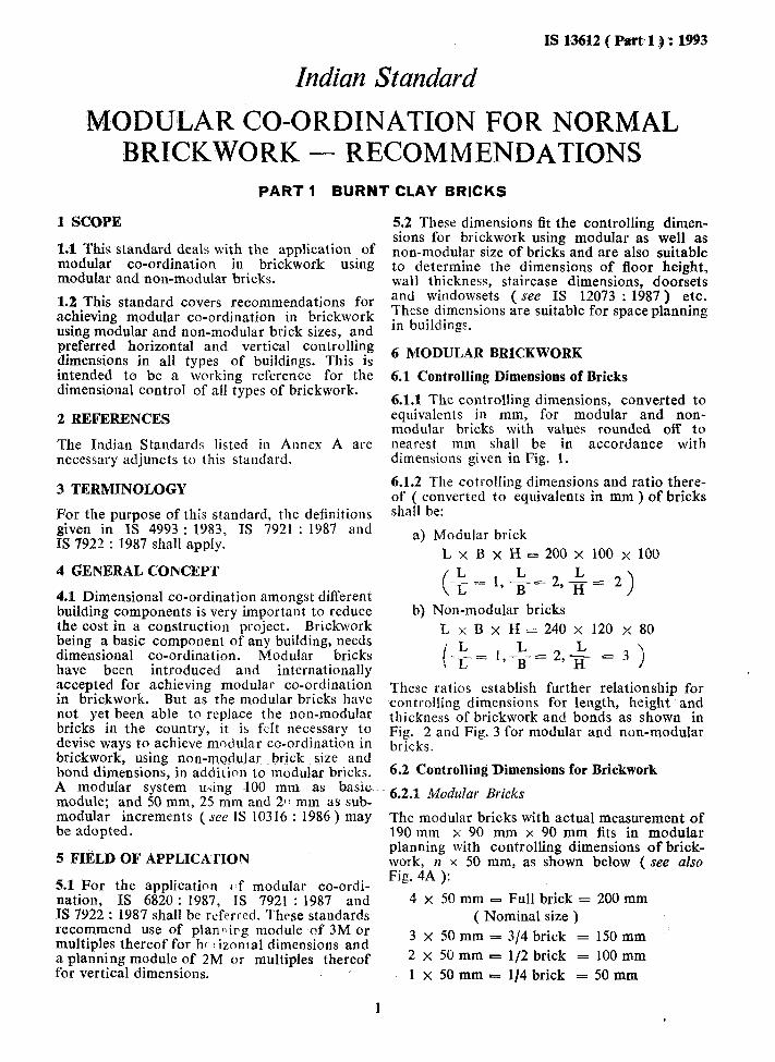
6.1.1 The controlling dimensions, converted to equivalents in mm, for modular and non- modular bricks with values rounded off to nearest mm shall be in accordance with dimensions given in Fig. 1.
6.1.2 The cotrolling dimensions and ratio there- of ( converted to equivalents in mm ) of bricks shall be:
a) Modular brick
LxBxH== 200 x 100 x 100
( L -=1,-$2,+ 2) L
b) Non-modular bricks
L x B x H= 240 x 120 x 80
i L -‘m2 = 1,+ = 2, j$ = 3 >
These ratios establish further relationship for controlling dimensions for length, height and thickness of brickwork and bonds as shown in Fig. 2 and Fig. 3 for modular and non-modular bricks.
6.2 Controlling Dimensions for Brickwork
6.2.1 Modular Bricks
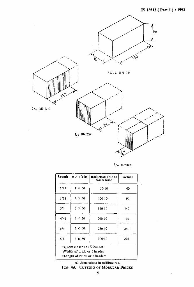
The modular bricks with actual measurement of 190 mm x 90 mm x 90 mm fits in modular planning with controlling dimensions of brick- work, ~2 x 50 mm, as shown below ( see also Fig. 4A ):
4x50mm- Full brick = 200 mm ( Nominal size )
3 x 50 mm = 3/4 brick = 150 mm 2x50mm = l/2 brick = 100 mm
lx50mm = l/4 brick = 50 mm
I

IS 13612 (Part 1)~:1993
6.2.1.1 For modular bricks, using sub-modular’ M
increments of - , the controlling dimensions 2
for brick walls, which are multiples of -y
( 50 mm ) for both, horizontal and vertical dimensions, match with the modular dimensions ( see Fig. 5A >.
6.2.2.1 For non-modular bricks, using sirb-
modular increments of -F the controlling
dimensions for brick walls, Lvhich are multiples of 60 mm ( = 3 x 20 mm ) for horizontal and 80 mm ( = 4 x 20 mm ) multiples of 80 mm ( = 4 x 20 mm ) for vertical direction, match with the modular dimensions ( see Fig. 5B).
6.2.2 Non-modular Bricks 6.3 Horizontal Co-ordination
The non-modular bricks with the measurement 240 mm x 120 mm x 80 mm fits in modular planning with controlling dimensions of brick- work, n x 60 mm, as shown below ( see also Fig. 4B ):
6.3.1 Considering the length and breadth of modular bricks, the horizontal controlling dimension of 3M can be achieved as follows:
4 x 60 mm = Full brick = 240 mm
Six times ( 50 mm or l/4 brick interval ) =6x50LZ3M
( Nominal size )
3 x 60 mm = 3/4 brick = 180 mm
2 x 60 mm = l/2 brick = 120 mm
1 x 60 mm = 114 brick - 60 mm
6.3.2 Considering the length and breadth of non-modular bricks, the horizontal controlling dimensions of 3M can be achieved as follows:.
Five times ( 60 mm or 114 brick interval ) = 5 x 60 = 3M
Controlling Dimensfons
L
200
Nominal Actual
B H L ’ B H
-- loo 90 loo -- 190 90
50 40
Non-Modular
FIG. 1 CONTROLLING DIMENSIONS OF BRICK
‘2
IS 13632
0
O- 2A ENGLISH BOND
2~ FLEMiSH 801’;O
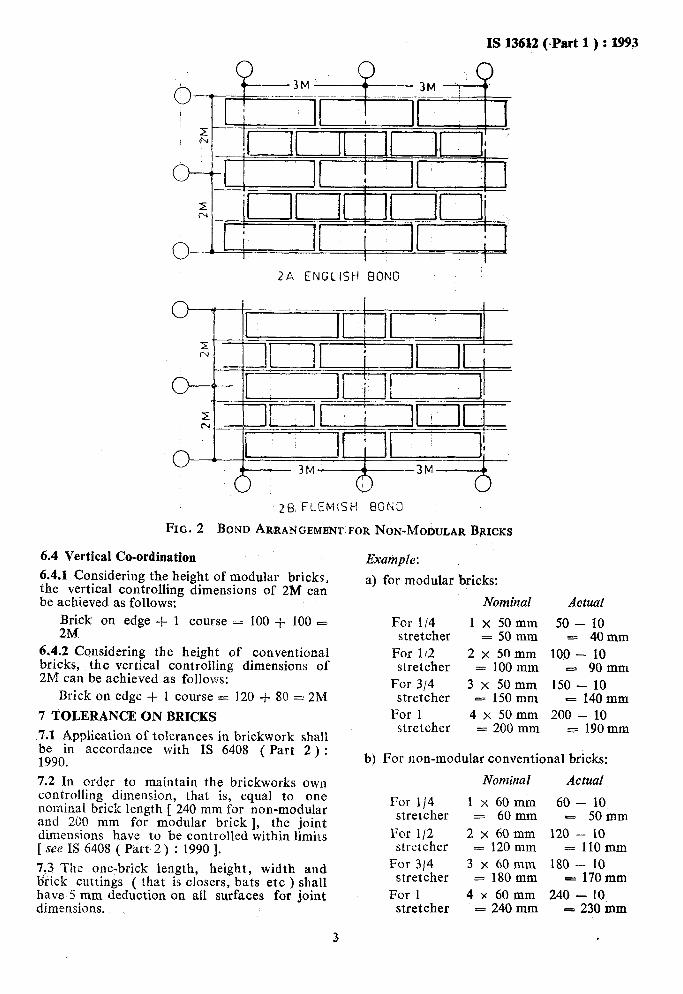
FIG. 2 BOND ARRANGEMENT FOR NON-MODULAR BRICKS
6.4 Vertical Co-ordination
6.4.1 Considering the height of modular bricks, the vertical controlling dimensions of 2M can be achieved as follows:
Brick on edge + 1 course = 100 + 100 - 2M
6,4.2 Considering the height of conventional bricks, the vertical controlling dimensions of 2M can be achieved as follows:
Brick on edge + 1 course = 120 + 80 = 2M
7 TOLERANCE ON BRICKS
7.1 Application of tolerances in brickwork shall be in accordance with IS 6408 ( Part 2 ) : 1990.
7.2 In order to maintain the brickworks own controlling dimension, that is, equal to one nominal brick length [ 240 mm for non-modular and 200 mm for modular brick 1, the joint dimensions have to be controlled within limits [ see IS 6408 ( Part 2 ) : 1990 1.
7,3 The one-brick length, height, width and brick cuttings ( that is closers, bats etc ) shall have S mm deduction on all surfaces for joint dimensions.
Example: I
a) for modular bricks:
For 114 stretcher
For 112 stretcher
For 314 stretcher
For 1 stretcher
Nominal
lx50mm = 50mm
2x5omm = 100 mm
3 x 50mm = 150 mm
4x50mm = 200 mm
(-Part 1 ) : 1993
Actual
50 - 10 = 40mm
100 - 10 - 90mm
150 - 10 - 140 mm
200 - 10 = 190mm
bj For non-modular conventional bricks:
Nominal Actual
For l/4 stretcher
For l/2 stretcher
For 314 stretcher
For 1 stretcher
lx60mm = 60mm
2x60mm = 120 mm
3x60mm = 180mm
4x60mm = 240 mm
60 - 10 - 50mm
120 - 10 = 110mm
180 - 10 - 170mm
240 - 10 = 230 inm
3 .

IS 136%2 ( Part 1) : 1993
_ N I
I
38 FLEMISH BOND
FIG. 3 BOND ARRANGBMENT FOR MODULAR BRICKS
8 HORIZONTAL DIMENSIONS OF WALL 8.3 The preferred horizontal dimensions for
8.1 Modular Bricks brickwork shall be selected for controlling the length of the wall ( see 6.4).
8.1.1 The basic co-ordmating dimension for brickwork in horizontal plane shall be multiple
of $-- sub-modular increment ( 50
8.4 The ‘5-mm Rule’ shall be applied to specify
mm ), the horizontal dimension of wall and other
minus joint dimension, that is n x 50 mm- joint related measurement of openings in the wall (see IS 7921 : 1987 ).
dimension ( see Fig. 6 ).
8.2 Non-modular Bricks 9 VERTICAL DIMENSIONS OF WALL
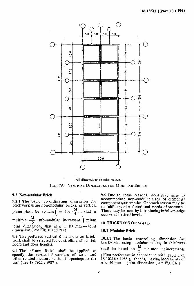
8.2.1 The basic co-ordinating dimension for 9.1 Modular Brick brickwork in horizontal plane shall be multiple
of 60 mm (
= 3 x $ that is, multiple of -5- M 9.1.1 The basic co-ordinating dimension for brickwork using modular bricks, in vertical plane
sub-modular increments 1
M , minus joint dimec- shall be - sub-modular increment ( 50 minus
2 sion, that is II x 60 mm joint dimension ( see joint dimension, that is, la x 50 mm -joint Fig. 6.). dimension ( see Fig. 6 and Fig. 7A ).
4
IS 13612 ( Part 1) : 1993
3/f, BRICK
Length II x 112 M Reduction Due to Actual 5-mm Rule
-7 ____ 1/4* 1 x 50 50-10 40 ---_
l/w 2 x 50 100-10 90 _.._-
314 3 x 50 150-10 140 _ _~ ~_~~. -___
4141: 4 x 50 200-10 190
514 5 x 50 250-10 240
614 6 x 50 300-10 290
*Quoin closer or l/2 header
tWidth of brick or 1 header
ILength of brick or 2 headers
All dimensions in millimetres.
FIG. 4A CUTTING OF MODULAR BRICKS
5

13~13612 ( Part 1) : 1993
FULL BRICK
3/L BRICK
Length
l/4’ _____
l/2? ---
314
4/4$
514
-
_
-
-
1 x 60 60-10 50
a----
2 X 60 120-10 110 ---__
3 x 60 180-10 170 -
4 x 60 240-10 -- -/
230
5 x 60 300-10 290
1 6X60 360-10 350
- nxl/5M ’ With Actual
5.mm Rule
*Quoin closer or 112 header TWidth of brick or Y header $Length of brick or 2 headers
All dimensions in millimetres.
FIG. 4B CUTTING OF NOK-MODULAR BRICKS
6

IS 13612 ( Part 1) : 1993
All dimensions in n~illirileir~s.
FIG 5A BOND DIMENSIONS FOR MODULAR BRICKS
All dimensions in millimetres.
FIG. 5B BOND DIMENSIONS FOR NON-MODULAR BRICKS
7

IS 13612 ( Part 1 ) : 1993
c; CONTROLLING DIMENSION n x3M 4
c> 6 68 PLAN
Brick Size 1 Co-ordinating Dimensions
Non- modular ( Conven- tional )
Modular
Horizontal
a, c and e =nx60mm-1Omm f = n X 80mm - 10mm b and cl =nxM + 10mm g and h = n X M + 10mm a+btc+d+e=WnX3M-10mm H =nx2M - 10mm
n, c and e -nX50mm-1Omm b and d -nxM + 10mm a+b+c+d+e=W=nx3M-1Omm
Vertical
f =nX50mm-IOmm g and I1 - n x M + 10mm H =nx2M - 10mm
All dimensions in millimetres.
FIG. 6 BRICKWORK CONTROLLING ~DIMENSIONS
‘Is 13612 ( Part 1) : 1993
All dhensions in millirnetres.
FIG. 7A VERTICAL DIMBNSIONS FOR MODULAR BRICKS
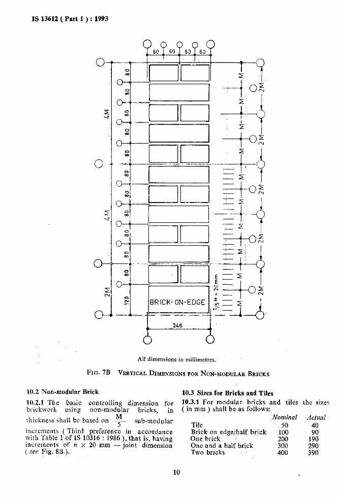
9.2 Non-modular Brick 9.5 Due to some reasons, need may arise to
9.2.1 The basic co-ordinating dimension for accommodate non-modular sizes of elements/
brickwork using non-modular bricks, in vertical components/assemblies. One such reason may be
( = 4 x q , that is
to fulfil specific functional needs of structure. plane shall be 80 mm These may be met by introducing brick-on-edge
course at desired levels.
multiple q sub-modular increment >
minus
joint dimension, that is n x 80 mm -joint 10 THICKNESS OF WALL
dimension ( see Fig. 6 and 7B ). 10.1 Modular Brick
9.3 The preferred vertical dimensions for brick- work shall be selected for controlling sill, lintel, 10.1.1 The basic controlling dimension for
room and floor heights. brickwork, using modular bricks, in thickness
9.4 The ‘5-mm Rule’ shall be applied to shall be based on -!I!- sub-modular increments
2 specify the vertical dimension of walls and (First preference in accordance with Table 1 of other related measurements of openings in the wall ( see IS 7922 : 1987 ).
IS 10316 : 1986 ), that is, having increments of II x 50 mm - joint dimension ( see Fig. 8A ).
9
IS 13612 ( Part 1) : 1993
c?--
All dimensions in millimetres.
FIG. 7B VERTICAL DIMENSIONS FOR NON-MODULAR BRICKS
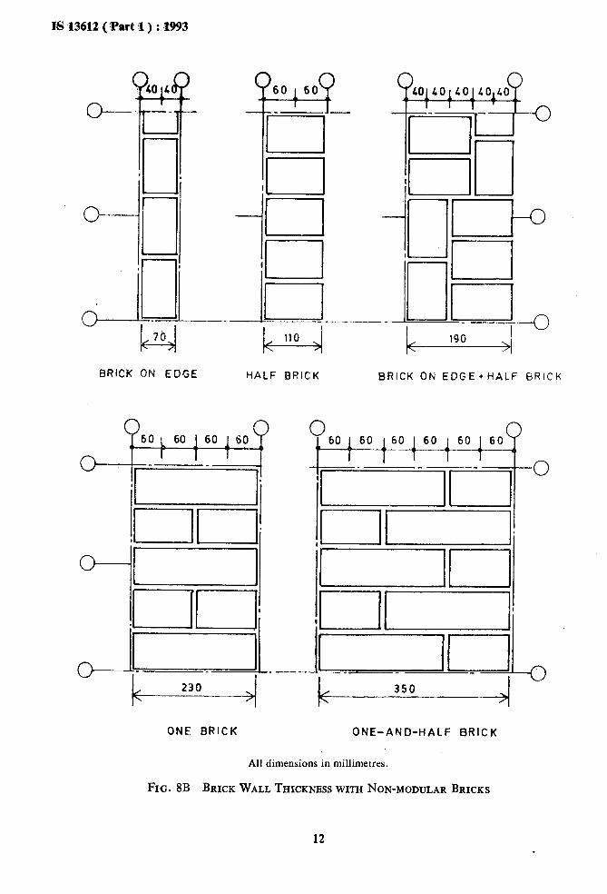
10.2 Non-modular Brick
10.2.1 The basic controlling dimension for bric.kwork using non-modular bricks, in
thickness shall be based on -I sub-modular
increments ( Third preference in accordance with Table 1 of I§ 10316 : 1986 ), that is, having increments of y1 x 20 mm - joint dimension ( see Fig. 8B-).
10.3 Sizes for Bricks and Tiles 10.3.1 For modular- bricks and tiles ( in mm ) shall be as follows:
Nominal Tile 50 Brick on edge/half brick 100 One brick 200 One an.d a half brick 300 Two bricks 400
the sizes
AClUd
40 90
190 290 390
10

IS 13612 ,( Part 1.) : 1993.
10.3.2 For non-modular bricks and tiles, the sizes are ( equivalent in mm ) shall be as follows:
11
Nom in al Actual
Tile 60 mm 50 mm Brick on edge 80 .mm 70 mm Half brick 120 mm 110 mm Half brick + brick on 200 mm 190 mm
edge One brick 240 mm 230 mm
One and a half brick 360 mm 350 mm Two bricks 480 mm 470 mm
CO-ORDINATE DIMENSIONING
11.1 Dimensions of brick wall shall be repre- sented on measurement line with actual
dimensions of wall for length, widthlthinckness and heights.
11.2 The actual dimensions of the wall openings shall be determined from the controlling dimensions plus one joint dimension.
11.3 The modular lines of openings in the wall shall be located along the centre line of joints.
11.4 Co-ordinating dimensions of actual openings shall be 10 mm more and wall dimen- sions shall be 10 mm less than modular dimensions.
12 LOCATION OF WALL
It shall be in accordance with Indian Standard Recommendations for modular co-ordination in building industry : location of structural walls and floor slabs ( under preparation ).
YALF BRICK ONE BRiCK O&E AND HALF BRICK
All dimensions in millimetres.
FIG. 8A BRICK WALL THICKNBSSES WITH MODULAR BRICKS
11
fS 13612 (‘Part d ) : ,I993
BRlCK ON EDGE
--iTI-‘- iii-l”
II (IUH
I . . . I I ._ _ I ” k-=-l 1YlJ
A HALF BRICK BRICK ON EDGE*HALF BRICK
350
ONE BRICK ONE-AND-HALF BRICK
All dimensions in millimetres.
FIG. 8B BRICK WALL THICKNESS WITH NON-MODULAR BRICKS
12
IS 1362 ( Part 1 ) : 1993
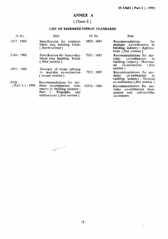
ANNEX A
( Clause 2 )
LIST OF REFERRED INDIAN STANDARDS
IS No. Title IS No. Title
1077 : 1986 Specification for common burnt clay building bricks (fourth revision )
2180 : 1988 Specification for heavy-duty burnt clay building bricks ( third revision )
4993 : 1983 Glossary of terms relating to modular co-ordination ( .recond revision )
6408 Recommendations for mo- ( Part 2 ) : 1990 dular co-ordination tole-
rances in building industry : Part 2 Principles and applications (first revision )
6820 : 1987
7921 : 1987
7922 : 1987
10316: 1986
Recommendations for modular co-ordination in building industry : Applica- tions (first revision ) Recommendations for mo- dular co-ordination . building industry : Horizoz tal co-ordination (first revision ) Recommendations for mo- dular co-ordination ’ building industry : Verticz co-ordination (Jirst revision )
Recommendations for mo- dular co-ordination basic module and sub-moduIar increments
13

Standard Mark The use of the Standard Mark is governed by the provisions of the Bureau of Indian
Standards Act, 2986 and the Rules and Regulations made thereunder. The Standard Mark on products covered by an Indian Standard conveys the assurance that they have been produced to comply with the requirements of that standard under a well defined system of inspection, testing and quality control which is devised and supervised by BIS and operated by the producer. Standard marked products are also continuously checked by BIS for con- formity to that standard as a further safeguard. Details of conditions under which a licence for the use of the Standard Mark may be granted to manufacturers or producers may be obtained from the Bureau of Indian Standards.
.
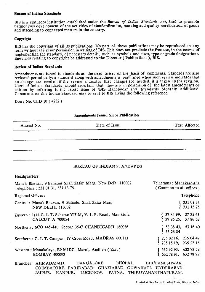
Bureau of Indian ZWndards
BE is a statutory institution established under the Bureau of Indian Standards Act, 1986 to promote harmonious development of the activities of standardization, marking and quality certification of goods and attending to connected matters in the country.
Copyright
BIS has the copyright of all its publications. No part of these publications may be reproduced in any form without the prior permission in writing of BIS. This does not preclude the free use, in the course of implementing the standard, of necessary details, such as symbols and sizes, type or grade designations. Enquiries relating to copyright be addressed to the Director ( Publications ), BIS.
Review of Indian Standards
Amendments are issued to standards as the need arises on the basis of comments. Standrds are also reviewed periodically; a standard along with amendments is reaffirmed when such review indicates that no changes are needed; if the review indicates that changes are needed, it is taken up for revision. Users of Indian Standards should ascertain that they are in possession of the latest amendments or edition by referring to the latest issue of ‘BIS Handbook’ and ‘Standards Monthly Additions’. Comments on this Indian Standard may be sent to BLS giving the following reference:
Dot : No. CED 10 ( 4232 )
Amendments Issued Since Publication
Amend No. Date of Issue Text Affected
BUREAU OF INDIAN STANDARDS
Headquarters:
Manak Bhavan, 9 Bahadur Shah Zafar Marg, New Delhi 110002 Telephones : 331 01 31, 331 13 75
Regional Offices :
Central : Manak Bhavan, 9 Bahadur Shah Zafar Marg NEW DELHI 110002
Eastern : I/ 14 C. I. T. Scheme VII M, V. I. P. Road, Maniktola CALCUTTA 700054
Northern : SC0 445-446, Sector 35-C CHANDIGARH 160036
Telegrams : Manaksanstha ( Common to all offices )
Telephone
I
331 01 31 331 13 75
I
37 84 99, 37 85 61 37 86 26, 37 86 62
I
53 38 43, 53 16 40 53 23 84
Southern : C. I. T. Campus, IV Cross Road, MADRAS 600113
I
235 02 16, 235 04 42 235 15 19, 235 23 15
Western : Manakalaya, E9 MIDC, Marol, Andheri ( East )
{
632 92 95, 632 78 58 BOMBAY 400093 632 78 91, 632 78 92
Branches : AHMADABAD. BANGALORE. BHOPAL. BHUBANESHWAR. COIMBATORE. FARIDABAD. GHAZIABAD. GUWAHATI. HYDERABAD. JAIPUR. KANPUR. LUCKNOW. PATNA. THIRUVANANTHAPURAM.
. Printed at New India Printing Press, Tihurja, IndriL