Embed Size (px)
Citation preview

Disclosure to Promote the Right To Information
Whereas the Parliament of India has set out to provide a practical regime of right to information for citizens to secure access to information under the control of public authorities, in order to promote transparency and accountability in the working of every public authority, and whereas the attached publication of the Bureau of Indian Standards is of particular interest to the public, particularly disadvantaged communities and those engaged in the pursuit of education and knowledge, the attached public safety standard is made available to promote the timely dissemination of this information in an accurate manner to the public.
इंटरनेट मानक
“!ान $ एक न' भारत का +नम-ण”Satyanarayan Gangaram Pitroda
“Invent a New India Using Knowledge”
“प0रा1 को छोड न' 5 तरफ”Jawaharlal Nehru
“Step Out From the Old to the New”
“जान1 का अ+धकार, जी1 का अ+धकार”Mazdoor Kisan Shakti Sangathan
“The Right to Information, The Right to Live”
“!ान एक ऐसा खजाना > जो कभी च0राया नहB जा सकता है”Bhartṛhari—Nītiśatakam
“Knowledge is such a treasure which cannot be stolen”
“Invent a New India Using Knowledge”
है”ह”ह
IS 10052-2 (1999): Radio Disturbance and Immunity MeasuringApparatus and Methods, Part 2: Methods of Measurement ofDisturbances and Immunity [LITD 9: ElectromagneticCompatibility]


IS10052(Part2):1999 CISPR 16-2 ( 1996 )
Indian Standard
SPECIFICATlON FOR RADIO DISTURBANCE AND IMMUNITY MEASURING APPARATUS AND METHODS
PART 2 METHODS OF MEASUREMENT OF DISTURBANCES AND IMMUNITY
( First Revision )
ICS 33.100
CQ BIS 1999
BUREAU OF INDIAN STANDARDS MANAK BHAVAN, 9 BAHADUR SHAH ZAFAR MARG
NEW DELHI 110002
September 1999 Price Rs. 220.00

Electromagnetic Compatibility Sectional Committee, LTD 22
NATIONAL FOREWORD
This Indian Standard (Part 2) (First Revision) which is identical with CISPR 16-2 (1996) ‘Specification for radio disturbance and immunity measuring apparatus and methods - Part 2 : Methods of measurement of disturbances and immunity’ issued by Special Committee on Radio Interference (CISPR), was adopted by the Bureau of Indian Standards on the recommendation of the Electromagnetic Compatibility Sectional Committee and approval of the Electronics and Telecommunication Division Council.
This standard (Part 2) was originally published in 1982 and was largely based on CISPR 16 (1977) Section 2. IS 10052 (Parts 3 to 7) were based on Sections 3 to 7 of CISPR 16 (1977) respectively.
This revision is now being published to combine IS 10052 (Parts 2 to 7) covering methods of measurement of radio disturbance and immunity in a single standard as IS 10052 (Part 2) and also to align it with the latest edition of CISPR 16. Consequently, IS 10052 (Parts 3 to 7) have been withdrawn.
Radio disturbance and immunity measuring apparatus are covered in IS 10052 (Part 1).
In the adopted standard, certain conventions are not identical to those used in Indian Standards. Attention is particularly drawn to the following:
a) Wherever the words’lnternational Standard’ appear referring to this standard, they should be read as ‘Indian Standard’.
b) Comma (,) has been used as a decimal marker while in Indian Standards, the current practice is to use a point (.) as the decimal marker.
CROSS REFERENCES
In this adopted standard, reference appears to certain International Standards for which Indian Standards also exist. The corresponding Indian Standards which are to be substituted in their place are listed below along with their degree of equivalence for the editions indicated:
international Standard
IEC 50 ( 161 ) :1990 International IS 1885 ( Part 64/Set l&2 ) : 1987 Electro- Electrotechnical Vocabulary(lEV) technical vocabulary: Part 64 Electromagnetic - Chapter 161: Electromagnetic compatibility, Section 1 General terms, compatibility Section 2 Specific terms
IEC 83 :1975 Plugs and socket- outlets for domestic and similar general use - Standards
IS 1293 : 1998 Plugs and socket-outlets for household and similar purposes ( third revision )
CISPR 11 ( 1990 ) Limits and methods of measurement of electromagnetic disturbance characteristics of industrial, scientific and medial ( ISM ) radii-frequency equipment ( since revised in 1997 )
IS 6873 ( Part 4 ) : 1999 Limits and methods of measurement of radio disturbance charac- teristics : Part 4 Industrial, scientific and medical ( ISM ) radio-frequency equipment ( first revision )
CISPR 13 ( 1990 ) Limits and methods of measurement of radio interference characteristics of sound and television broadcast receivers and associated equip- ment ( since revised in 1996 )
IS 6873 ( Part 3 ) : 1999 Limits and methods of measurement of radio disturbance charact- teristics : Part 3 Sound and television broad- cast receivers and associated equipment ( first revision )
( Continued on third cover )
Corresponding lndian Standard Degree of Equivalence
Technically Equivalent
do
Identical
do

IS 10052 ( Part 2 ) : 1999 CISPR 16-2 ( 1996 )
CONTENTS
Page
Clause
1.1 Scope ........................................................................................................................................ .3
1.2 Normative references ............................................................................................................... 3
1.3 Definitions.. ............................................................................................................................... 3
SECTION 2: DISTURBANCE MEASUREMENTS
2.1
2.2
2.3
2.4
2.5
2.6
Types of disturbance to be measured ......................................................................................
Connection of measuring equipment ........................................................................................
General measurement requirements and conditions ...............................................................
Measurement of disturbances conducted along leads, Q kHz to 30 MHz ................................
Measurements using the absorbing clamp, 30 MHz to 1000 MHz.. .........................................
Measurement of radiated disturbances ......................................... ..- .......................................
6
6
7
10
24
25
3.1
3.2
3.3
SECTION 3: IMMUNITY MEASUREMENTS
Immunity test criteria and general measurement procedures ..................................................
Method of measurement of immunity for conducted signals ....................................................
Method of measurement of immunity to radiated electric field interference.. ...........................
SECTION 4: AUTOMATED MEASUREMENTS
Automated measurements (under consideration) ....................................................................
SECTION 5: FACTORS INFLUENCING MEASUREMENT ACCURACY
Factors influencing measurement accuracy .............................................................................
32
35
36
4.1
5.1
43
43
SECTION 1: GENERAL
Figures . . . . . . . . . . . . . . . . . . . . . . . . . . . . . . . . . . . . . . . . . . . . . . . . . . . . . . . . . . . . . . . . . . . . . . . . . . . . . . . . . . . . . . . . . . . . . . . . . . . . . . . . . . . . . . . . . . . . . . . . ...........*......... 44
Annexes
A Guidelines to connection of electrical equipment to the artificial mains network . . . . . . . . . . . . . . . . . . . . . . . .
B Use of spectrum analyzers and scanning receivers.. . . . . . . . . . . . . . . . . . . . . . . . . . . . . . . . . . . . . . . . . . . . . . . . . . . . . . . . . . . . . . . . . . .
C Historical background to the method of measurement of the interference power produced by electrical household and similar appliances in the VHF range . . . . . . . . . . . . . . . . . . . . . . . . . . . . . . . . . . . . . . . . . . . . . . . . . . . .
65
72
74
1

As in the Original Standard, this Page is Intentionally Left Blank

IS 10052 ( Part 2 ) : 1999 CEPR 16-2 ( 1996 )
Indian Standard
SPECIFICATION FOR RADIO DISTURBANCE AND IMMUNITY MEASURING APPARATUS AND METHODS
PART 2 METHODS OF MEASUREMENT OF DISTURBANCES AND IMMUNITY
( First Revision )
1.1 Scope
This part of CISPR 16 specifies the methods of measurement of EMC phenomena in the frequency range 9 kHz to 18 GHz.
1.2 Normative references
The following normative documents contain provisions which, through reference in this text, constitute provisions of this part of CISPR 16. At the time of publication, the editions indicated were valid. All normative documents are subject to revision, and parties to agreements based on this part of CISPR 16 are encouraged to investigate the possibility of applying the most recent editions of the normative documents indicated below. Members of IEC and IS0 maintain registers of currently valid international Standards.
IEC 83: 1975, PIugs and socket-outlets for domestic and similar general use - Standards
IEC 364-4: Electrical installations of buildings - Part 4: Protection for safety
CISPR 11: 1990, Limits and methods of measurement of electromagnetic disturbance characteristics of industrial, scientific and medical (ISM) radio-frequency equipment
CISPR 13: 1990, Limits and methods of measurement of radio interference characteristics of sound and television broadcast receivers and associated equipment
CISPR 14: 1985, Limits and methods of measurement of radio interference characteristics of household electrical appliances, portable tools and similar electrical apparatus
CISPR 14: 1993, Limits and methods of measurement of radio disturbance characteristics of electrical motor-operated and thermal appliances for household and similar purposes, electric tools and electric apparatus
CISPR 16-l : 1993, Specification for radio disturbance and immunity measuring apparatus and methods - Part 1: Radio disturbance and immunity measuring apparatus
ITU-R 468: Measurement of audio-frequency noise voltage level in sound broadcasting
1.3 Definitions
For the purpose of this part of CISPR 16, the definitions of Iid 50(161) apply, as well as the following:
1.3.1 associated equipment:
1) Transducers (e.g. probes, networks and antennas) connected to a measuring receiver or test generator.
2) Transducers (e.g. probes, networks, antennas) which are used in the signal or disturbance transfer between an EUT and measuring equipment or a (test-) signal generator.
3

IS 10052 ( Part 2 ) : 1999 CEPR 16-2 (1996)
1.3.2 EUT: The equipment (devices, appliances and systems) subjected to EMC (emission and immunity) compliance tests.
. .
1.3.3 product publication: Publication product family, taking into account specific
1.3.4 emission limit (from a disturbing
specifying EMC requirements for a product or aspects of such a product or product family.
source): The specified maximum emission level of a source of electromagnetic disturbance. [IEV 161-03-121
1.3.5 immunity limit: The specified minimum immunity level. [IEV 161-03-151
1.3.6 ground reference: A connection that constitutes a defined parasitic capacitance to the surrounding of an EUT and serves as reference potential.
NOTE - See also IEV 161-04-36.
1.3.7 (electromagnetic) emission: The phenomenon by which electromagnetic energy emanates from a source. [IEV 161-01-061
1.3.6 Immunity (to a disturbance): The ability of a device, equipment or system to perform without degradation in the presence of an electromagnetic disturbance. [IEV 161-01-201
1.3.9 coaxial cable: A cable containing one or more coaxial lines, typically used for a matched connection of associated equipment to the measuring equipment or (test-)signal generator providing a specified characteristic impedance and a specified maximum allowable cable transfer impedance.
1.3.10 common mode (asymmetrical disturbance voltage): The RF vottage between the artificial midpoint of a two-conductor line and reference ground, or in case of a bundle of lines, the effective RF disturbance voltage of the whole bundle (vector sum of the unsymmetrical voltages) against the reference ground measured with a clamp (current transformer) at a defined terminating impedance.
NOTE - See also IEV 161-04-09.
1.3.11 common mode current: The vector sum of the currents flowing through two or more conductors at a specified cross-section of a “mathematical” plane intersected by these conductors.
1.3.12 differential mode voltage; symmetrical voltage: The RF disturbance voltage between the wires of a two conductor line. [IEV 161-04-06, modified]
1.3.13 differential mode current: Half the vector difference of the currents flowing in any two of a specified set of active conductors at a specified cross-section of a “mathematical” plane intersected by these conductors.
1.3.14 unsymmetrical mode (V-terminal voltage): The voltage between a conductor or terminal of a de,vice, equipment or system and a specified ground reference. For the case of a two-port network, the two unsymmetrical voltages are given by:
a) the vector sum of the asymmetrical voltage and half of the symmetrical vottage; and
b) the vector difference between the asymmetrical voltage and half of the symmetrical voltage.
NOTE - See also IEV 161-04-13.
IS 10052 ( Part 2) : 1999 CEPR 16-2 ( 1996 )
1.3.15 measuring receiver: A receiver for the measurement of disturbances with different detectors.
NOTE - The receiver is specified according to CISPR 16-l.
1.3.16 test configuration: Gives the specified measurement arrangement of the EUT in which an emission or immunity level is measured.
NOTE - The emission level or immunity level is measured as required by IEV 161-03-11, IEV 161-03-12, IEV 161-03-14 and IEV 161-03-15, definitions of emission level and immunity level.
1.3.17 artificial network (AN): An agreed reference load (simulation) impedance presented to the EUT by actual networks (e.g., extended power or communication lines) across which the RF disturbance voltage is measured.
1.3.18 artificial mains network (AMN): A network inserted in the supply mains lead of apparatus to be tested which provides, in a given frequency range, a specified load impedance for the measurement of disturbance voltages and which may isolate the apparatus from the supply mains in that frequency range. [IEV 161-04-051
1.3.19 weighting (quasi-peak detection): The repetition-rate dependent conversion of the peak-detected pulse voltages to an indication corresponding to the psychophysical annoyance of pulsive disturbances (acoustically or visually) according to the weighting characteristics, or alternatively gives the specified manner in which an emission level or an immunity level is evaluated.
NOTES
1 The weighting characteristics are specified in CISPR 16-1.
2 The emission level or immunity level is evaluated as required by IEC 50(161) definitions of level (see IEV 161-03-01, IEV 161-03-11 and IEV 161-03-14).
1.3.20 continuous disturbance: RF disturbance with a duration of more than 200 ms at the IF-output of a measuring receiver, which causes a deflection on the meter of a measuring receiver in quasi-peak detection mode which does no? decrease immediately. [IEV 161-02-l 1, modified]
NOTE - The measuring receiver is specified in CISPR 16-l.
1.3.21 discontinuous disturbance: For counted clicks, disturbance with a duration of less than 200 ms at the IF-output of a mea,suring receiver, which causes a transient deflection on the meter of a measuring receiver in quasi-peak detection mode.
NOTES
1 For impulsive disturbance, see IEV 161-02-08.
2 The measuring receiver is specified in CISPR 18-1.
5

IS 10052 (Part 2) : 1999 CEPR 16-2 (1996.)
Section 2: Disturbance measurements
2.1 Types of disturbance to be measured
This subclause describes the classification of different types of disturbance and the detectors appropriate for their measurement.
2.1.1 Types of disturbance
For physical and psychophysical reasons, dependent on the spectral distribution, measuring receiver bandwidth, the duration, rate of occurrence, and degree of annoyance during the assessment and measurement of radio disturbance, distinction is made between the following types of disturbance:
a) narrowband continuous disturbance, i.e. disturbance on discrete frequencies as, for example, the fundamentals and harmonics generated with the intentional application of RF energy with ISM equipment, constituting a frequency spectrum consisting only of individual spectral lines whose separation is greater than the bandwidth of the measuring receiver so that during the measurement only one line falls into the bandwidth in contrast to b);
b) broadband continuous disturbance, which normally is unintentionally produced by the repeated impulses of, for example, commutator motors, and which have a repetition frequency which is lower than the bandwidth of the measuring receiver so that during the measurement more than one spectral line falls into the bandwidth; and
c) broadband discontinuous disturbance is also generated unintentionally by mechanical or electronic switching procedures, for example by thermostats or programme controls with a repetition rate lower than 1 Hz (click-rate less than 30/min).
The frequency spectra of b) and c) are characterized by having a continuous spectrum in the case of individual (single) impulses and a discontinuous spectrum in case of repeated impulses, both spectra being characterized by having a frequency range which is wider than the bandwidth of the measuring receiver specified in CISPR 16-1.
2.1.2 Detector functions
Depending on the types of disturbance, measurements may be carried out using a measuring receiver with:
a) an average detector generally used in the measurement of narrowband disturbance and signals, and particularly to discriminate between narrowband and broadband disturbance;
b) a quasi-peak detector provided for the weighted measurement of broadband disturbance for the assessment of audio annoyance to a radio listener, but also usable for narrowband disturbance;
c) a peak detector which may be used for either broadband or narrowband disturbance measurement.
Measuring receivers incorporating these detectors are specified in CISPR 16-l.
2.2 Connection of measuring equipment
This subclause describes the connection of measuring equipment, measuring receivers and associated equipment such as artificial networks, voltage and current probes, absorbing clamps and antennas.
6

IS 10052 ( Part 2 ) : 1999 CEPR 16-2 ( 1996 )
2.2.1 Connection of associated equipment
The connecting cable between the measuring receiver and the associated equipment shall be shielded and its characteristic impedance shall be matched to the input impedance of the measuring receiver.
The output of the associated equipment shall be terminated with the prescribed impedance.
2.2.2 Connections to RF reference ground
The artificial mains network (AMN) shall be connected to the reference ground by a low RF impedance, e.g. by direct bonding of the case of the AMN to the reference ground or reference wall of a shielded room, or with a low impedance conductor as short and as wide as practical (maximum length to width ratio is 3:l).
Terminal voltage measurements shall be referenced only to tne reference ground. Ground loops (common impedance coupling) shall be avoided. This should also be observed for measuring apparatus (e.g. measuring receivers and connected associated equipment, such as oscilloscopes, analyzers, recorders, etc.) fitted with a protective earth conductor (PE) of Protection Class I equipment. If the PE connection of the measuring apparatus and the PE connection of the power mains to the reference ground do not have RF isolation from the reference ground, the necessary RF isolation shall be provided by means such as RF chokes and isolation transformers, or if applicable, by powering the measuring apparatus from batteries,’ so that the RF connection of the measuring apparatus to the reference ground is made via only one route.
For the treatment of PE connection of the EUT to the reference ground, see clause A.4.
Stationary test configurations do not require a connection with the protective earth conductor It the reference ground is connected directly and meets the safety requirements for protective earth conductors (PE connections).
2.2.3 Connection between the EUT and the artificial mains network
General guidelines for the selection of grounded and non-grounded connections of the EUT to the AMN are discussed in annex A.
2.3 General measurement requirements and conditions
Radio disturbance measurements shall be:
a) reproducible, i.e. independent of the measurement location and environmental conditions, especially ambient noise;
b) free from interactions, i.e. the connection of the EUT to the measuring equipment shall neither influence the function of the EUT nor the accuracy of the measurement equipment.
These requirements may be met by observing the following conditions:
c) existence of a sufficient signal-to-noise ratio at the desired measurement level, e.g. the level of the relevant disturbance limit;
d) having a defined measuring set-up, termination and operating conditions of the EUT;
e) having a sufficiently high impedance of the probe at the measuring point, in the case of voltage probe measurements;
f) when using a spectrum analyzer or scanning receiver due considerations shall be given to its particular operating and calibration requirements.
7
IS 10052 (Part 2) : 1999 CISPR 16-2 (1996)
2.3.1 Disturbance not produced by the equipment under test
The measurement signal-to-noise ratio with respect to ambient noise shall meet the following requirements. Should the spurious noise level exceed the required level, it shall be recorded in the test report.
2.3.1 .l Compliance testing
A test site shall permit emissions from the EUT to be distinguished from ambient noise. The ambient noise level should preferably be 20 dB, but at least be 6 dB below the desired measurement level. For the 6 dB condition, the apparent disturbance level from the EUT is increased by up to 3,5 dB. The suitability of the site for required ambient level may be determined by measuring the ambient noise level with the test unit in place but not operating.
In the case of compliance measurement according to a limit, the ambient noise level is permitted to exceed the preferred -6 dB level provided that the level of both ambient noise and source emanation combined does not exceed the specified limit. The EUT is then considered to meet the limit. Other actions can also be taken; for example, reduce the bandwidth for narrowband signals and/or move the antenna closer to the EUT.
NOTE - If both the ambient field strength and field strength of ambient and EUT are measured separately, it may be possible to provide an estimate of the EUT field strength to a quantifiable level of uncertainty. Reference is made in this respect in annex C of CISPR 11.
2.3.2 Measurement of continuous disturbance
2.3.2.1 Narrowband continuous disturbance
The measuring set shall be kept tuned to the discrete frequency under investigation and returned if the frequency fluctuates.
2.3.2.2 Broadband continuous disturbance
For the assessment of broadband continuous disturbance the level of which is not steady, the maximum reproducible measurement value shall be found. See 2.3.4.1 for further details.
2.3.2.3 Use of spectrum analyzers and scanning receivers
Spectrum analyzers and scanning receivers are useful for disturbance measurements, particularly in order to reduce measuring time. However, special consideration must be given to certain characteristics of these instruments, which include: overload, linearity, selectivity, normal response to pulses, frequency scan rate, signal interception, sensitivity, amplitude accuracy and peak, average and quasi-peak detection. These characteristics are considered in annex B.
2.3.3 Operating conditions of the EUT
The EUT shall be operated under the following conditions:
2.3.3.1 Normal load conditions
The normal load conditions shall be as defined in the product specification relevant to the EUT, and for EUTs not so covered, as indicated in the manufacturer’s instructions.
2.3.3.2 The time of operation
The time of operation shall be, in the case of EUTs with a given rated operating time, in accordance with the marking; in all other cases, the time is not restricted.
8

IS 10052 ( Part 2 ) : 1999 CISPR 16-2 ( 1996 )
2.3.3.3 Running-in time
No specific running-in time, prior to testing, is given, but the EUT shall be operated for a sufficient period to ensure that the modes and conditions of operation are typical of those during the life of the equipment. For some EUTs, special test conditions may be prescribed in the relevant equipment publications.
2.3.3.4 Supply
The EUT shall be operated from a supply having the rated voltage of the EUT. If the level of disturbance varies considerably with the supply voltage, the measurements shall be repeated for supply voltages over the range of 0,9 to 1 ,l times the rated voltage. EUTs with more than one rated voltage shall be tested at the rated voltage which causes maximum disturbance.
2.3.3.5 Mode of operation
The EUT shall be operated under practical conditions which cause the maximum disturbance at the measurement frequency.
2.3.4 Interpretation of measuring results
2.3.4.1 Continuous disturbance
a) If the level of disturbance is not steady, the reading on the measuring receiver is observed for at least 15 s for each measurement; the highest readings shall be recorded, with the exception of any isolated clicks, which shall be ignored (see 4.2 of CISPR 14).
b) If the general level of the disturbance is not steady, but shows a continuous rise or fall of more than 2 dB in the 15 s period, then the disturbance voltage levels shall be observed for a further period and the levels shall be interpreted according to the conditions of normal use of the EUT, as follows:
1) if the EUT is one which may be switched on and off frequently, or the direction of rotation of which can be reversed, then at each frequency of measurement the EUT should be switched on or reversed just before each measurement, and switched off just after each measurement. The maximum level obtained during the first minute at each frequency of measurement shall be recorded;
2) if the EUT is one which in normal use runs for longer periods, then it should remain switched on for the period of the complete test, and at each frequency the level of disturbance shall be recorded only after a steady reading (subject to the provision that item a) has been obtained).
c) If the pattern of the disturbance from the EUT changes from a steady to a random character part way through a test, then that EUT shall be tested in accordance with item b).
d) Measurements are taken throughout the complete spectrum and are recorded at least at the frequency with maximum reading and as required by the relevant CISPR publication.
2.3.4.2 Discontinuous disturbance
Measurement of discontinuous disturbance may be performed at a restricted number of frequencies. For further details, see CISPR 14.
9

IS 10052 ( Part 2 1 l 1999 .~_\. . ..--.+ .--- CISPR 16-2 ( 1996 )
2.3.4.3 Measurement of the duration of disturbances
The EUT is connected to the relevant artificial mains network. If a measuring set is available, it is connected to the network and a cathode-ray oscilloscope is connected to the i.f. output of the measuring set. If a receiver is not available, the oscilloscope is connected directly to the network. The time base of the oscilloscope can be started by the disturbances to be tested; the time base is set to a value of 1 ms/div -10 ms/div for EUT with instantaneous switching and 10 ms/div - 200 ms/div for other EUT. The duration of the disturbance can either be recorded directly by a storage oscilloscope or digital oscilloscope or by photograph or hard copy recording of the screen.
.2.4 Measurement of disturbances conducted along leads, 9 kHz to 30 MHz
2.4.1 introduction
When testing for compliance with emission limits for electromagnetic disturbances conducted along leads, the following items shall be considered as minimum, both in the standardized situation (type tests) and at the place of installation (in situ tests):
a) ,I.- &.,-a... -6 rlL‘.*r&.#.rrrr. ,l.r..,. a._ ,..#A m-+krAr -4 -A.-,r,,r;-” _A”A‘,_,AA rli”+,,rhlnnar ,110 lyyc;s “, “‘3L”,“LIIIGG’J. ‘,\lci,0 cI,ci LII” ,lllZ,lI”“3 “I rrlr;ca3”r,,ry &#“II”“~,~” “lJL”lYcIII~=~‘ either as a voltage (prevailing method for CISPR measurements) or as a current. Both methods can be used to measure the three types of conducted disturbances, i.e:
- common mode (also called asymmetrical mode)
- differential mode (also called symmetrical mode)
- unsymmetrical mode
NOTE - The unsymmetrical mode voltage is primarily measured at the mains network. The common mode voltage (or current) is measured primarily for signal and control lines.
b) the measuring equipment: the type of measuring equipment is chosen in relation to the ’ disturbance properties to be determined (see 2.4.2);
c) the associated equipment: the type of associated equipment, i.e., artificial networks, current probes or voltage probes, is chosen in accordance with the type of disturbance to be measured in accordance with 2.4.1 a). Each type of associated equipment presents RF loading to the measured signals and lines (see 2.4.3);
d) RF load conditions of the disturbance source: the measuring set-up will present certain RF load impedances to the disturbance source(s) in the EUT. These impedances are standardized in type tests or might depend on the conditions at the place of installation in the case of in situ tests (see 2.4.3 and 2.4.4);
e) the test configuration of EUT: a standardized test configuration shall specify the -_~______ ___.._-I IL- ___l.I__ -1 IL- #-,,-I- ---_-:-I-_I reverence grouno, rne poslrlon or rne cu I ZUid assoclawa FiCX%Surii?g iXjuipi_iiWii WiGi respect to that reference ground, connections to that reference ground and interconnections of the EUT with the associated equipment (see 2.4.4 and 2.4.5).
2.4.2 Measuring equipment (receivers, etc.)
!!? nC%nnChl 2 riictinrtinn ad dicrmntinlmllr rlictlrrhancaa y”‘lYl CA,, “,“.,I I”.I”I I is rlrawn hntwmnn rnntinlmllc “I%%..,, ““...““I, ““I..IIIY”“” U..” “r.s_“......“““” 1.1.1.-w..__-. Continuous radio-frequency disturbances are predominantly measured in terms of frequency domain parameters. Discontinuous disturbances are also measured in terms of frequency domain parameters but may need additional time domain measurements.
The measuring sets and other measuring equipment specified in CISPR 16-1 shall be used. For time domain measurements oscilloscopes etc. may be used.
1C

IS 10052 ( Part 2) : 1999 CEPR 16-2 ( 1996 )
2.4.3 Associated measuring equipment
Associated measuring equipment for conducted disturbance measurement is divided into two categories:
a) voltage measuring sensors, such as artificial networks (AN) and voltage probes;
NOTE - The artificial network is sometimes referred to as impedance simulation network (ISN).
b) current measuring sensors, such as current probes.
2.4.3.1 Artificial networks (AN)
The common mode, differential and unsymmetrical mode impedances of actual networks, such as of power mains and telephones, are location dependent and, in general, time varying. Therefore, type testing of disturbance requires standardized impedance simulation networks, referred to as artificial networks (AN). The AN provides standardized RF load impedances to the EUT. For this purpose, the AN is inserted in series with the terminals of the EUT and the actual network or signal simulator. In this way the AN simulates extended networks (long lines) with defined impedances.
2.4.3.1 .l Types of artificial networks
The ANs specified in CISPR 16-1 shall be used, unless specific reasons call for another construction. In general three types of AN can be distinguished:
a) the V-type AN: in a defined frequency range the RF impedances between each of the EUT terminals to be measured and the reference ground have a defined value, whereas no impedance component is connected directly between these terminals. The construction defines (indirectly) both the differential and common mode voltage measured. In principle, there is no limit for the number of EUT terminals, i.e. for the number of lines to be measured by V-type ANs;
b) the Delta-type AN: in a defined frequency range the RF impedance between a pair of EUT terminals to be measured and between these terminals and the reference ground have a defined value. This construction defines directly both the differential and the common mode RF load impedances.
Addition of a balance/unbalance transformer makes it possible to measure the symmetric and asymmetric disturbance voltage;
c) the T-type AN: in a defined frequency range the common mode RF impedance between a pair of EUT terminals to be measured and a reference ground has a defined value. In general, no defined differential load impedance is included in a T-type AN as such. The defined differential impedance must then be provided by the external circuit connected to the supply (line) terminals of the T-type AN. This type of AN is used to measure common mode disturbance voltages only.
2.4.3.1.2 Minimum requirements
The AN shall meet the following minimum requirements:
a) in a defined frequency range the AN shall provide defined RF impedances between the terminals of the EUT to be measured and between these terminals and the reference ground. By meeting this requirement, the disturbance source to be measured is loaded in a defined manner if, in addition, the test configuration (see 2.4.4) is defined;
b) if the AN is intended to separately measure common mode and/or differential mode disturbances (see 2.4.3.1 .l), the rejection ratio of differential to common mode signals, and vice versa, shall be specified in the appropriate frequency range;
c) in a defined frequency range there shall normally be an isolation between the defined RF impedances and the actual network (or a signal simulator) so that the loading of the AN by the actual network (or the signal simulator) does not unduly influence the value of any of the defined RF impedances;
11

IS 10052 ( Part 2) : 1999 CISPR 16-2 ( 1996 )
d) the AN shall provide a defined connection (connector) to which the defined measuring equipment can be connected, in order to make a defined test configuration possible. The input connector shall be suitable for measuring equipment with 50 R input impedance as defined in CISPR 16-1;
e) the AN shall provide a defined connecting point to which the reference ground can be connected, in order to make a defined test configuration possible;
f) the AN shall be calibrated according to a prescribed procedure.
2.4.3.1.3 Additional requirements
The AN shall have the following additional requirements:
a) the AN shall contain a decoupling or blocking network to prevent:
- damage of the components forming the defined RF impedances by the wanted line voltages of the network, such as the mains voltage,
- damage of the components forming the defined RF impedances by peak voltages produced by the EUT, such as switching transients,
- influence of the rated line voltages on the measuring results, for example overload of the input stage of the measuring equipment;
b) the AN shall contain a filter to prevent intentional signals on the actual network or the signal simulator influencing the measuring results.
2.4.3.2 Voltage probes
For standardized voltage probes, see CISPR 16-1.
Disturbance voltages on terminals which are not to be measured with an AN can be measured with a voltage probe. Examples of such terminals are connecting jacks for antennas, control lines, signal lines and load lines. In general the voltage probe is used to measure the common mode disturbance voltage. The probe presents a high RF impedance between the terminal to be measured and the reference ground.
2.4.3.2.1 Minimum requirements
a) In a defined frequency range the voltage probe shall provide a high RF impedance between its measuring tip and the reference ground so as not to affect the voltage to be measured.
b) The voltage probe shall have a blocking capacitor of such a value to ensure that line voltage cannot damage the measuring receiver.
c) The voltage probe shall provide a defined 50 Q connection (connector) to which the standardized measuring receiver can be connected, in order to make a defined disturbance measurement.
d) The voltage probe shall provide a defined connection point to which the reference ground can be connected in a defined manner via a lead of defined maximum length unless the reference ground is connected to the EUT in another specified way.
e) The voltage probe shall be calibrated according to a prescribed procedure, where this procedure shall account for parasitic effects near the test point, for example unwanted capacitive coupling between the test point and the screening of the probe. The voltage division between probe impedance and input impedance of measuring equipment shall be independent of frequency or accounted for in the calibratioh process.
f) The voltage probe name-plate shall state the maximum line voltage.
12

2.4.3.3 Current probes
IS 10052 ( Part 2) : 1999 CISPR 16-2 ( 1996 )
Current probes or current transformers allow the measurement of all three types of disturbance current (see 2.4.1) on mains leads, signal lines, load lines etc. A clip-on construction of the probe will facilitate its use.
The common mode current on leads is measured when the current probe is clipped around those leads, regardless of the number of wires. In this situation, the differential mode currents on the leads will induce signals with equal magnitude but opposite sign, so that these signals cancel to a high degree. The latter effect allows the measurement of a common mode current with a small amplitude in the presence of differential mode (operating) currents with large amplitude.
For already defined (and standardized) current probes see CISPR 16-l.
2.4.3.3.1 Minimum requirements
a) In a defined frequency range the current probe shall have a defined transfer impedance, that is, a defined ratio of the RF voltage induced in the probe and the known RF current on a single wire running through the probe, as measured in a specified way.
b) In a defined frequency range the insertion loss caused by the current probe, that is of the EUT, shall be less than 1 Q.
c) The current probe shall be constructed in such a way that the influence of electric fields on the measuring results can be neglected.
d) The current probe shall provide a defined connection (connector) to which the defined (and standardized) measuring equipment can be connected, in order to make a defined test configuration possible. In addition, the input impedance of the measuring equipment to be used in connection with the current probe shall be indicated.
e) The current probe specification shall include the maximum current rating before saturation effects will take place.
f) The current probe shall be calibrated according to a prescribed procedure.
2.4.4 Equipment test configuration
2.4.4.1 Disposition of equipment under test and its connection to the artificial network
For measurement of the disturbance voltage the equipment under test (EUT) is connected to the power supply mains and any other extended network via one or more artificial network(s) (in general, the V-type network is used for this purpose) (see figure l), in accordance with the following requirements. Other CISPR publications supply additional test details relevant to particular EUTs.
An EUT, whether intended to be grounded or not, and which is to be used on a table is configured as follows:
- either the bottom or the rear of the EUT shall be at a controlled distance of 40 cm from a reference groundplane. This groundplane is normally the wall or floor of a shielded room. It may also be a grounded metal plane of at least 2 m by 2 m. This is physically accomplished as follows:
. place the EUT on a table of non-conducting material which is at least 60 cm high. Place the EUT so that it is 40 cm from the wall of the shielded room, or
. place the EUT on a table of non-conducting material which is 40 cm high so that the bottom of the EUT is 40 cm above the groundplane;
- all other conductive surfaces of the EUT shall be at least 80 cm from the reference groundplane;
13
IS 10052 ( Part 2 ) : 1999 CISPR 16-2 ( 1996 )
- the ANs are placed on the floor as shown in figure 1 in such a way that one side of the AN housings is 40 cm from the vertical reference ground plane and other metallic parts;
- the EUT cable connections shall be as shown in figure 1;
- the optional test configuration for table-top EUT with only a power cord attached is shown in figure 2.
Floor-standing EUTs are subject to the same provisions as above with the exception that they shall be placed on a floor, the points of contact being consistent with normal use. A ground- connected floor of metal shall be used but shall not make metallic contact with the floor support(s) of the EUT. The metal floor may be used as the reference ground plane and shall extend at least 50 cm beyond the boundaries of the EUT and have minimum dimensions of 2 m by 2 m. For examples of test configurations, see figures 3 and 4.
The artificial network is RF bonded to the reference groundplane by a low radio-frequency impedance connection.
NOTE - The “low” radio-frequency impedance value should preferably be less than 10 R at 30 MHz. This can, for example, be achieved if the housing of the artificial network is mounted directly to the reference ground plane or its connection strap has a length-to-width ratio not more than 3:l.
The EUT is located so that the distance between the boundary of it and the closest surface of the artificial network is 80 cm.
The power mains leads to an artificial network and the connecting cable from the network to the measuring receiver must be arranged in such a way that their locations do not influence the measurement results. EUTs, which are not equipped with fixed connecting leads, are connected to the artificial network with a 1 m long lead as specified in the relevant equipment documentation.
If the EUT is to be connected to a reference ground this shall be done by means of a lead running parallel to the EUT mains lead and of the same length at a distance of not more than 10 cm from it, unless a ground conductor is contained in the mains lead itself. If a fixed lead is attached to the EUT this shall be 1 m long, or if in excess of 1 m, part of the lead is folded back and forth in the shape of a meander, as far as possible so as to form a bundle not exceeding 40 cm in length, and arranged in the form of a non-inductive serpentine in such a way that the total length of the lead does not exceed 1 m (see also figure 5). However, when the bundled lead may influence the measurement results, a shortening of the length to 1 m is recommended.
2.4.4.2 Procedure for the measurement of unsymmetric disturbance voltages with V-networks
2.4.4.2.1 Disposition of equipment with ground connection
For equipment under test which is required to be grounded during its operation, or the conductive housing of which can come into contact with ground, the unsymmetric radio interference voltage of the individual mains lead is measured with reference to the reference metal wall (general mass of the measuring equipment) to which the housing of the equipment under test is connected via its protective ground conductor and the ground connection of the artificial mains network (see the equivalent circuit in figure 6).
The parameters determining the interference potential of grounded test units are discussed in clause A.3.
For EUTs with two or more power and safety conductors or special ground connections the measurement result depends much on the termination conditions of the mains terminals and the grounding conditions (refer also to 2.4.5 on measurement in systems).
14

IS 10052 ( Part 2) : 1999 CISPR l&2(1996)
As the ground safety conductors in the actual mains power supply installation may have a considerable length, and therefore do not guarantee a ground impedance as low and effective as in the standard test set-up with only a 1 m long ground wire connection to the reference mass, and moreover, since safety conductors need not be used on every product per IEC 364-4, disturbance voltage measurements on pluggable Class I appliances shall be carried out according to 2.4.4.2.2, also without the safety or ground wire being connected (non-grounded measurement). If however for safety reasons it is necessary to maintain the safety function of ground wires, this can be achieved by the use of an RF choke or impedance equal to the network impedance of a V-network in the safety wire path.
Exceptions may be made for non-radiating or well screened EUTs which have to be grounded according to special requirements or instructions (see A 2.1 and A 4.1).
2.4.4.2.2 Disposition of equipment without ground connection
Devices without ground connection comprise electrical devices with protective insulation (protection Class II) and devices which can be operated without ground or safety conductor (device of protection Class III) and also pluggable protection Class I devices connected via an isolating transformer. For these devices, the unsymmetrical disturbance voltage of the individual conductors must be measured with respect to the metal reference ground of the measurement arrangement as shown in the equivalent circuit of figure 7.
Since in the long and medium wave bands (0,15 MHz to 2 MHz) the results of measurement can be considerably influenced by the low series capacitance C2 between the EUT and the
reference ground, and since it is determined by the specified distance, the arrangement must be exactly followed and other external influence such as body and hand capacitance, for example, should be avoided.
2.4.4.2.3 Disposition of handheld equipment without a ground connection.
Measurements shall first be made in accordance with 2.4.4.2.2. Additional measurements shall then be made using the artificial hand described in CISPR 16-l.
The general principle to be followed in the application of the artificial hand is shown in figure 9. Terminal M of the RC element shall be connected to any exposed non-rotating metal work and to metal foil wrapped around all handles, both fixed and detachable, supplied with the EUT. Metalwork which is covered with paint or lacquer is considered as exposed metalwork and shaH be directly connected to the RC element.
The artificial hand shall consist of metal foil wrapped around the case, or part thereof, as specified below. The foil shall be connected to one terminal (terminal M) of an RC element (see figure 8) consisting of a capacitor of 220 pF * 20 % in series with a resistor of 510 Q f 10 %; the other terminal of the RC element shall be connected to the reference earth of the measuring system.
The artificial hand is to de applied the following way:
a) when the,case of the EUT is entirely of metal, no metal foil is needed, but the terminal M of the RC element shall be connected directly to the body of the EUT;
b) when the case of the EUT is of insulating material, metal foil shall be wrapped around the handle 6 (figure 9), and also around the second handle D, if present. Metal foil 60 mm wide shall also be wrapped around the body C at that point where the iron core of the motor stator is located or around the gearbox if this gives a higher emission level. All these pieces of metal foil, and the ring or bushing A, if present, shall be connected together and to the terminal M of the RC element;
15

IS 10052 (Part 2) : 1999 CISPR 16~2(1996)
c) when the case of the EUT is partly metal and partly insulating material, and has insulating handles, metal foil shall be wrapped around the handles B and D (figure 9). If the case is non-metallic at the location of the motor, a metal foil 60 mm wide shall be wra,pped around the body C at that point where the iron core of the motor stator is located, or alternatively around the gearbox, if this is of insulating material and a higher emission level is obtained. The metal part of the body, the point A, the metal foil round the handles B and D and the metal foil on the body C shall be connected together and to the terminal M of the RC element;
d) when the EUT has two handles of insulating material A and B and a case of metal C, for example an electric saw (figure lo), metal foil shall be wrapped around the handles A and B. The metal foil at A and B and the metal body C shall be connected together and to the terminal M of the RC element.
2.4.4.2.4 Disposition of keyboards, electrodes and other equipment sensitive to human touch
In the case of such equipment the artificial hand shall be applied as required by the product specifications and in general according to 2.4.4.2.3.
2.4.4.2.5 Disposition of equipment with external suppression components
If interference suppression devices are attached outside the EUT (e.g. in a plug device for cormection to the mains) or as an element inserted in the connecting cable (power cord emission suppression device), or if shielded power cords are used, an additional 1 m long unshielded cable must be connected between the emission suppression device and the artificial network for measurement of the disturbance voltage. The line between the device and the emission suppression device must be placed in the direct proximity of the test object.
2.4.4.2.6 Disposition of equipment having auxiliary apparatus connected at the end of a lead other than the mains lead
NOTES
1 Regulating controls incorporating semiconductor devices are excluded from this subclause; the provisions of 2.4.4.4.1 shall apply.
2 When the auxiliary apparatus is not essential to the operation of the EUT and has a separate test procedure specified elsewhere, this subclause does not apply. The main EUT is tested as an individual EUT.
3 The ultimate decision whether to measure and apply limits is to be made in the relevant CISPR product publication.
Connecting leads exceeding 1 m in length shall be bundled in accordance with 2.4.4.1.
Measurements are not required when the connecting lead between EUT and auxiliary apparatus is permanently fixed on both ends and is either shorter than 2 m or shielded,
+ provided that in the latter case the shielded lead is connected at both ends to the metal housing of the EUT and that of the auxiliary apparatus. Leads with removable plugs and sockets are considered to be extendable to a length of more than 2 m and measurements are required.
The equipment under test shall be arranged in accordance with previous parts of 2.4.4.2, with the following additional requirements:
a) the auxiliary apparatus shall be placed at the same height as and at the same distance from the grounded conducted surface and if the lead is long enough, it is to be treated in accordance with 2.4.4.1. If the auxiliary lead is shorter than 0,8 m, its length shall be maintained, and the auxiliary apparatus shall be placed as far away as possible from the main apparatus. When the auxiliary apparatus is a control, the arrangements for its operation must not affect the level of disturbance;
16
b) if an EUT having connected. If the EUT
IS 10052 ( Part 2) : 1999 CISPR 16-2 ( 1996 )
an auxiliary apparatus is grounded, no artificial hand shall be itself is made to be held in the hand, the artificial hand shall be
connected to the EUT and not to any auxiliary apparatus;
c) if the EUT is not made to be held in the hand, auxiliary apparatus which is not grounded and is made to be held in the hand must be connected to the artificial hand. If the auxiliary apparatus is not made to be held in the hand either, it shall be placed in relation to a grounded conducting surface as described in 2.4.4.1.
In addition to the measurement on the terminals for the mains connection, measurements are conducted on all other terminals for incoming and outgoing leads (e.g. control and load lines) using a voltage probe connected to the input of the measuring receiver.
The auxiliary apparatus, control or load is connected to allow measurements to be made under all provided operating conditions and during interactions between the EUT and the auxiliary apparatus.
Measurements are performed both on the power input terminals of the EUT and the power input terminals of the auxiliary apparatus.
2.4.4.3 Measurement of common mode voltages at differential mode signal terminals
2.4.4.3.1 Measurement using the delta-type network
The common mode disturbance voltage at the terminals for differential mode signal lines of telecommunication, data processing and other equipment is measured with delta-networks in accordance with 11.6 of CISPR 16-1, in the frequency range 150 kHz to 30 MHz. The delta- networks specified in CISPR 16-1 could be amended in order to allow signal and d.c. current paths needed for the proper functioning of the EUT as long as the requirements on differential mode and common mode impedances of CISPR 16-1 are complied with.
When using the delta network for measurements on signal terminals, the differential mode rejection must be as great as needed not to give erroneous results when measuring a common mode disturbance voltage at the same frequency as the operational differential mode signal.
When the EUT is to be measured on its power supply terminals using an artificial mains network all voltage measurements shall be carried out with both networks connected simultaneously. The provisions prescribed in 2.4.4.1 and 2.4.4.2 are to be observed.
NOTE - The freauencv ranae of the delta-network can be extended to 9 kHz usina the same network impedance if beco;pling of the connected receiver are designed accordingly.
2.4.4.3.2 Measurements using the T-type network
Alternatively a common mode artificial network, e.g.
signal line and coupling to the” measuring
a T-type network according to clause 20 of CISPR 16-1, can be used for the measurement of common mode disturbance voltages in
, the frequency range 9 kHz to 30 MHz.
In contrast to the delta-network which provides a differential mode and a common mode
termination with equal simulation impedances of 150 Q, the T-network provides only a
common mode termination of 150 $2 and almost no loading and high isolation to the differential
mode operational signal on the communication line.
At the supply side of the T-type network a signal simulator, load circuits for d.c. or the operational signal frequency of the EUT or other circuits needed for the operation of the EUT can be connected. These circuits shall either themselves provide a differential mode RF
resistance of 100 R - 150 C2, as required for the particular EUT, or with a termination to
17

IS 10052 ( Part 2) : 1999 CISPR l&2(1996)
provide this resistance. When no external‘circuit is specified for the operation of the EUT a resistor of 150 Q shall be connected as differential mode RF termination to the T-type network. Figure 11 shows an example of a T-type network.
2.4.4.4 Measurements using voltage probes
2.4.4.4.1 With an artificial mains network
In order to test devices and systems with several connected or connectable lines, the disturbance voltage at the line connections, which cannot be measured with artificial mains networks (e.g. for connecting lines between parts of components which are separated from the mains) as well as the connecting jacks for antennas, control and load lines, must be measured with a voltage probe with a high input impedance (1500 a or more) to ensure that the lines are not loaded by the probe.
For these cases, however, the primary power input wires must be isolated and RF terminated with the AMN. For the remaining lines, also those not to be measured with the probe, the corresponding conditions of 2.4.4.1 and the operating conditions laid down for the individual devices in the respective product specifications (e.g. CISPR 11 and CISPR 14) must be observed in regard to arrangement and length. The voltage probe is connected to the measuring receiver via a coaxial cable, the screen of which is connected to the ground reference and the case of the voltage probe. No connection shall be made directly from this case to live parts of the EUT.
Figure 12 shows an example for a test set-up for measuring the interference voltage of a semi- conductor regulating control.
2.4.4.4.2 Without an artificial mains network
During testing of EUTs which are not to be measured with artificial mains networks, the disturbance voltage is measured across a defined simulation resistance (e.g. artificial fence simulation in 5.4.1 of CISPR 14 or under open-circuit conditions with an exactly defined arrangement and line layout taking into consideration the specifications of 2.4.4.1). The disturbance voltage is measured with a high-impedance voltage probe.
This is valid also for e.g. power electronic devices which are fed from their own separate power supplies or battery devices to which separateiy installed lines are connected which are not to be loaded.
In the case of disturbance voltage measurements on separate individual power sources for currents of more than 25 A (e.g. battery, generator, convertor), an impedance measurement must be applied to ascertain that the tolerance of the simulated resistance, in accordance with CISPR 16-1 is not exceeded.
The flexible ground connection for probes with an input impedance Rx of more than 1500 R should not be longer than l/10 of the wave-length at the maximum measurement frequency and shall be connected in the shortest possible way to the metal surface serving as reference ground. In order ‘to avoid additional capacitive loading of the test point by the screening of the probe, the tip of the probe should not exceed a length of approximately 3 cm. The screened connections to the measuring receiver must be arranged in such a way that the capacitance of the test object is not altered with respect to the reference ground.
18

IS 10052 ( Part 2 ) : 1999 CEPR 16-2 ( 1996 )
2.4.4.5 Measurements using current probes
Disturbance current measurements may be useful for several reasons. The first is that in some devices it may not be possible to insert an artificial mains network. This is particularly true when tests are performed on installed systems, or where the EUT has very high currents. A second reason for the use of the current probe is that at the lower end of the frequency range the mains impedance becomes very low, so the disturbance source is a current generator. The measurement of this current can be made by means of a current transformer without interrupting or disconnecting the mains connection.
Current probes shall conform to the requirements of clause 12 of CISPR 16-l.
Current probes enable the direct measurement of the D common mode components of the. disturbance current by enclosing the cable containing all leads. Therefore, common mode disturbance currents can be easily separated from differential mode operating currents.
If measurements are performed with known load and source impedances, the disturbance voltage can be calculated.
If only one conductor is enclosed, the superposition of the differential and common mode disturbance current components is measured. If, in this case, any extremely high (above 200 A) operating current exists, there is a risk of false data because the magnetic core of the current probe may saturate.
2.4.5 System test configuration for conducted emissions measurements
2.4.5.1 General approach to system measurements
The general objective of defining a system test configuration for conducted emission measurements has the following key points:
- avoiding common mode disturbance ground loops;
- defining a configuration which is easily duplicated;
- decoupling of lines not being measured from the line being measured;
- placing of lines to achieve decoupling;
- duplicating requirements in 2.4.1 to 2.4.4 for the system test to the maximum extent possible.
Whenever possible, the disturbance voltage on a system line shall be measured with an AN. For currents up to 50 A, ANs can be used quite easily. The AN shall be installed within 80 cm of the system equipment being measured. Each wire of a multi-wire power mains circuit shall
be routed through an AN. Each AN shall be terminated with a 50 Q resistor at the measurement terminal.
The EUT shall be arranged and connected with cables terminated in accordance with the manufacturer’s instructions.
For some measurements, relevant product publications may state a specific load to be used together with load voltage probes, instead of an AN. A voltage probe may also be used for conducted measurements when the mains current is above 50 A and an appropriate AN is not available. In this latter case test results with an AN will take precedence over the results with a voltage probe, however.
For some measurements, the use of current probes may’be specified in the relevant product publication.
19

IS 10052 ( Part 2) : 1999 CEPR 16-2 (1996)
2.4.5.2 System configuration /
The system shall be carefully configured, installed, arranged and operated in a manner that is most representative of the system as typically used (i.e. as specified in the instruction manual) or as specified herein. Equipment that typically operates within a system made up of multiple interconnected units should be tested as part of such a typical operational system.
Generally, the system that is tested shall be of the same type that is supplied to the end user. If the marketing information is not available or it is not practical to assemble extraordinary amounts of equipment to replicate a complete product installation, the test shall be performed using the best judgement of the test engineer in consultation with the design engineering staff. The results of any such discussion and decision process shall be documented in the test report.
The selection and placement of cables, a.c. line cords, host and peripherals depends on the type of EUT and must be representative of expected equipment installation. Three types are distinguished. First, there are systems normally used entirely on one table top. A second type of system consists of equipment normally used in a floor-standing configuration. These include systems mounted over a specially designed raised floor which facilitates intra-system connection under the raised floor. Equipment making up the floor-standing system can be interconnected with cabling lying on the floor, under the floor in a raised floor installation, or overhead according to normal installation. Third, there are systems that are a combination of floor-standing and table-top systems. The remainder of this clause provides instructions for the testing of each of these systems. In addition, the specific requirements in 2.4.1 to 2.4.4 shall be observed.
Equipment in a system, normally being floor-standing, shall be placed on a floor in accordance with 2.4.4.1. Equipment designed for both table-top and floor operation shall be tested only in the table-top configuration.
2.4.5.2.1 Operating conditions
The system shall be operated at the rated (nominal) operating voltage and typical load conditions - mechanical or electrical, or both - for which it is designed. Loads may be actual or simulated as described in the individual equipment requirements. For some systems, it may be necessary to develop a set of explicit requirements specifying the test conditions, operations, etc. to be used in testing a specific system.
If the system includes a visual display unit or monitor, the following operating conditions apply unless the product publication specifies otherwise:
a) set the contrast control to maximum;
b) set the brightness control to maximum or at raster extinction if raster extinction occurs at less than maximum brightness;
c) for colour monitors, use white letters on a black background to represent all colours;
d) select the worst case of positive or negative video if both are available;
e) set character size and number of characters per line so that the maximum number of characters per screen is displayed;
f) for a monitor that has no graphics capabilities, regardless of the vraeo card used, a pattern consisting of random text shall be displayed;
g) for a monitor with graphics capabilities, even though another video card may be needed to accomplish a graphic display, a pattern consisting of a line of scrolling Hs should be displayed;
h) if a monitor has no text capabilities, use a typical display.
20

IS 10052(Part2):1999 CEPR 16-2 ( 1996 )
2.4.5.2.2 Interfacing equipments, simulators and cables
Compliance testing is performed with peripheral and cable placement which is judged realistic and likely to be found in the final installation. Figures 1, 3, 4 and 5 describe standardized test set-ups which will provide a basis for repeatability among testing laboratories and is consistent with the requirement for a realistic system and cable orientation. Any deviation from the standard test set-ups shall be documented together with its supporting rationale.
Since a system is required to interact functionally with other units, the actual interfacing units should be used. Si’mulators may be used to provide representative operating conditions, provided the effects of the simulator used in lieu of an actual interfacing unit properly represent the electrical, and in some cases the mechanical, characteristics of the interfacing units, especially concerning RF signals, impedances and shield terminations. Because of the ad&d degree of uncertainty when a simulator is used, such use should be avoided if possible. In case of a dispute, measurements made with an actual interfacing unit shall take precedence. If a device is designed to be used only with a specific host computer or peripheral, it should be tested with that computer or peripheral.
Interfacing cables should be typical of normal use as supplied with the normal system and at least 2 m long unless the manufacturer’s user manual specifies shorter cables. The same type of cable (that is, non-shielded, braided shield, foil shield, etc.) specified in the user manual should be used throughout the tests. Excessive lengths of cable shall be folded into a serpentine-like bundle at the approximate centre of the cable with the bundles 30 cm to 40 cm in length.
If shielded or special cables are used during the tests to achieve compliance, then a statement must be included in the test report and in the instruction manual advising of the need to use those types of cables.
Interface ports (connectors) shall have a cable connected to one of each type of functional interface port of the system, and each cable shall be terminated in a device typical of actual usage. Where there are multiple interface ports all of the same type, additional connecting cables shall be added to the system to determine the effect these cables have on emissions from the system.
.
Normally, the loading of similar ports is limited to the following:
a) availability of multiple loads (for large systems);
b) reasonableness of multiple loads representing a typical installation.
The rationale for the selection of the configuration and loading of ports shall be included in the test report; that is 28 % of possible cables were connected and the emissions did not increase by more than 2 dB when one or more cables were added. Additional ports on support units, interfacing units or simulators, other than those associated with the system or the minimum required system, need not be connected or used during testing.
2.4.5.2.3 Mains connection
If the system is an assembly of equipment each having its own power cords, the point of connection for the ANs is determined from the following rules:
a) each power cord which terminates in a mains supply plug of a standard design (IEC 83, for example) shall be tested separately;
b) power cords or terminais which are not\ specified by the manufacturer to be connected via a host unit shall be tested separately;
21

IS 10052 ( Part 2) : 1999 CISPR 16-2 ( 1996 )
c) power cords or field wiring terminals which are specified by the manufacturer to be connected to a host unit or other power-supplying equipment shall be connected to that host unit or other power-supplying equipment, and the terminals or cords of that host unit or other power-supplying equipment are connected to the ANs and tested;
d) where a special mains connection is specified, the necessary connection hardware to the AN shall be supplied by the manufacturer for the purpose of the test.
The ground safety conductor of units separately powered shall be isolated from the equipment
under test by a 50 pH AN in the frequency range 0,15 MHz to 30 MHz. The normal AN mains input is connected to the reference ground in this use of the AN as a filter.
2.4.5.3 Measurements of interconnecting lines
In addition to the measurement on the terminals for the mains connection, measurements may need to be performed with a voltage probe on other terminals for incoming and outgoing leads (for example control and load lines). If the function of the equipment under test is affected by the 1500 Q impedance of the probe, the impedance at 50/60 Hz and at radio frequencies may
need to be increased (for example 15 kQ in series with 500 pF). In place of a voltage measurement, a current measurement with a current probe may also be used, if required (or offered as an option) in the product specification.
During the measurement, the ANs on the mains lead remain in place to provide a defined mains isolation and a defined RF termination. The auxiliary apparatus (control, load) is connected to allow measurements to be made under all provided operating conditions and during interactions between the equipments. Measurements are made on the specified terminals of each equipment.
If the connecting lines between equipments are permanently fixed on both ends and either shorter than 2 m or shielded, no measurements are necessary, provided that in the latter case the shielded cable is connected at both ends to the reference ground, that is metal housing of the equipments. Non-shielded connecting lines with plug(s) or socket(s) are considered to be extendable to a length of more than 2 m and therefore must be extended by at least 2 m and must be tested. Shielded cables must be at least 2 m long unless the user manual specifies shorter cables.
2.4.5.4 Decoupling of system components
One of the sources of inaccurate conducted measurements in a system is any ground circulating current. This ground current may be interrupted by installing a 50 pH AN in the
frequency range 0,15 MHz - 30 MHz in the ground safety conductor to the EUT.
An additional source of circulating currents can be the shields of interconnecting cables between units. Therefore, the ground safety conductor to these units shall also be isolated by a 50 uH AN.
The measurement receiver should be referenced to ground only at the measurement point to prevent ground loops. (Caution: shock hazard may exist if the measuring set is not supplied with an isolation transformer.)
2.4.6 In situ measurements
Testing may be performed at the end user’s or manufacturer’s premises, if the system cannot be set up o.n test site. In this case, both the system and its location are considered as the system tested. The emission results are unique to the installation site because site containment properties affect the measurement. However, where testing of a given system has
22

IS 10052 ( Part 2) : 1999 CEPR 16-2 (1996)
been accomplished at three or more representative locations, the results may be considered representative of all sites with similar systems for purposes of determining compliance with emission requirements (if allowed in the procuring or requirement document.)
The disturbance voltage shall be measured under the existing conduction conditions with non- reactive pick-up devices (high resistance voltage probes). The conduction conditions and measurement results are affected by:
- the existing reference ground or the reference mass used during measurement. Neither a conducting ground plane nor an AN shall be installed for user’s installation testing unless one or both are to be a permanent part of the installation;
- the RF characteristics and loading conditions for the power mains conduction;
- the ambient RF environment; and
- the input impedance of the pick-up device.
2.4.6.1 Reference ground
The existing ground at the place of installation should be used as reference ground. This should be selected by taking high-frequency (RF) criteria into consideration. Generally, this is accomplished by connecting the EUT via wide straps, with a length-to-width ratio not exceeding 3, to structural conductive parts of buildings that are connected to earth ground. These include metallic water pipes, central heating pipes, lightning wires to earth ground, concrete reinforcing steel and steel beams.
In general, the safety and neutral conductors of the power installation are not suitable as reference ground as these may carry extraneous disturbance voltages and can have undefined RF impedances.
If no suitable reference ground is available in the surroundings of the test object or at the place of measurement, sufficiently large conductive structures such as metal foils, metal sheets or wire meshes set up in the proximity can be used as reference ground for measurement.
The general requirements of 2.4.4.2.1 and of annex A should be observed.
2.4.6.2 Measurement with voltage probes
Testing of conducted disturbance voltage is made with the voltage probe. Special precautions must be taken to establish a reference ground for the measurements.
Any voltage decrease caused by loading of the circuit to be measured can be determined qualitatively by varying the voltage probe input impedance. If the input impedance of the voltage probe is high compared to the internal impedance of the test point or of the tested network, then only slight differences in the measurement of the disturbance voltage occur when the probe input impedance is increased. The input impedance of the probe can be doubled by series connection of a 1500 G resistor. If the disturbance voltage is reduced by (the predicted) 5 dl3 or 6 dB, then the 1500 G probe can be used to measure the disturbance voltage.
2.4.6.3 Selection of measuring points
Radio disturbance voltage measurements at the place of installation are carried out at the boundaries of the user’s premises, of industrial areas, or at points to be specified within the influence area of receiving system.
23

IS 10052 ( Part 2 ) : 1999 CISPR 16-2 ( 1996 )
2.4.6.3.1 Measurements on mains and other supply leads
In power supply networks it is sufficient to measure the unsymmetric disturbance voltage with ,the voltage probe at accessible power outlets near the power entrance to the building.
2.4.6.3.2 Measurements on unshielded and shielded cables
In the case of non-shielded and shielded signal, control and load leads with non-grounded shield leaving the boundaries, the unsymmetric disturbance voltage shall be measured with the voltage probe on the individual wires or the screens against reference ground.
In the case of shielded cables with grounded shield, the common mode disturbance current is measured at a distance greater than one-tenth wavelength from the connecting and grounding points using a current probe.
2.5 Measurements using the absorbing clamp, 30 MHz to 1000 MHz
2.5.1 General
Absorbing clamps (see figure 13) are suitable for the measurement of the disturbance power that can be radiated from a cable for some types of equipment depending on construction and size. The precise measuring procedure and its applicability is to be specified in each product specification. If the dimensions of the EUT, without connecting leads, approach a quarter of a wavelength of the measuring frequency, direct cabinet radiation may occur and the absorbing clamp method is not suitable to assess the full radiation capacity of the EUT. In general,, the method is most useful for small EUTs and in the frequency range of 30 MHz to 300 MHz.
The disturbance potential of an EUT with a mains lead being the only external lead may be taken as the power it could supply to its main lead acting as a radiating antenna. This power is nearly equal to that supplied by the EUT to the absorbing clamp placed around the lead at the position where the absorbed power is maximum.
Equipment having external leads other than a mains lead can radiate disturbance from such leads, shielded .or unshielded, in the same manner as radiation from the mains lead. Absorbing clamp measurements can also be used on these leads for diagnostic purposes.
Radiation from leads at frequencies above 300 MHz, up to 1000 MHz, may be measured with a suitable absorbing clamp. Such measurements are also suitable for diagnostics. However, it should be noted that radiation could emanate directly from the equipment as well.
Historical background of the absorbing clamp is contained in annex C.
2.52 Measurements
When using the absorbing clamp, the EUT is placed on a non-metallic table at least 60 cm high. The lead to be measured is stretched horizontally in a straight line, to permit variation in position of the absorbing clamp along the lead to find the maximum indication. The lead shall be at least a half-wavelength at the lowest frequency of measurement, plus the length of the absorbing clamp and a possible second absorbing clamp: at 30 MHz the lead length is 6 m and with the second (filtering) absorbing clamp must be at least 7 m. Leads shorter than 1 m ! are not suitable for absorbing clamp measurements.
24

IS 10052(Part2):1999 CISPR 16-2 (1996)
The absorbing clamp is placed around the lead to be measured as shown in figure 13. The position of the absorbing clamp along the lead shall be varied from zero to one half- wavelength distance from the EUT at each test frequency. The maximum indication obtained on the measurement receiver connected to the absorbing clamp is proportional to ‘the disturbance power available.
When measurements are made on an EUT having more than one lead attached, detachable leads shall be removed if operationally possible, at the time when another lead is measured. A lead which cannot be removed shall be isolated by means of lossy ferrite rings or another absorbing clamp put around the lead immediately adjacent to the EUT.
The test arrangement for the absorbing clamp is shown in figure 13. No person or metallic objects shall be positioned within 80 cm of the measuring set-up. The required movement of the absorbing clamp may be performed with pulleys and a rope that is operated by a motor that can be operated from a remote location.
The power corresponding to the measured receiver voltage indication at each test frequency is derived from the absorbing clamp calibration procedure described in clause 13 of CISPR 18-1.
2.6 Measurement of radiated disturbances
2.8.1 /r/troducfion
This section sets forth the general procedures for the measurement of the field strength of radio disturbance produced by devices and systems. Experience with radiated disturbance measurements is less extensive than that of voltage measurements. The radiated disturbance measurement procedures are therefore open to revision and extension as knowledge and experience are accumulated. In particular, attention shall be given to the effect of leads and cables associated with the EUT.
For some products, it may be required to measure the electric, the magnetic, or both components of the radiated disturbance. Sometimes a measurement of a quantity related to radiated power is more appropriate. Normally measurements should be made of both the horizontal and vertical components of the disturbance with respect to the reference ground plane. The results of measurements of either the electric or magnetic components may be expressed in peak, quasi-peak, average or r.m.s. values.
The magnetic component of the disturbance is normally measured at frequencies up to 30 MHz. In magnetic field measurements only the horizontal component of the field at the position of the receiving antenna is measured when using the distant antenna procedure. If the large loop antenna (LLA) system is used, the three orthogonal magnetic dipole moments of the EUT are measured. (Note that in the single antenna method, the horizontal component of the field at the position of the antenna is determined by the horizontal and vertical dipole moments of the EUT, because reflection plays a part.)
2.8.2 Field-strength measurements
Field-strength measurements may be made on an open area test site, in an absorber-lined shielded enclosure, in a reverberating chamber or using a LLA system. For practical reasons other test sites may have to be specified.
2.8.2.1 Open area test site measurements /
The open area test site shall conform with the relevant specifications in clause 16 of CISPR 16-1 for its physical and electrical properties and for its validation.
25

IS 10052 ( Part 2 ) : 1999 CISPR 16-2 ( 1996 )
2.6.2.2 General measurement method
Figure 14 shows the concept of measurements made on an open area test site with the direct and ground reflected rays arriving at the receiving antenna.
The EUT is set up at a specified height above the ground plane and configured to represent normal operating conditions. The antenna is positioned at the specified separation distance. The EUT is rotated in the horizontal plane and the maximum reading noted. The height of the antenna is adjusted so that the direct and reflected rays approach or meet in-phase addition. The procedural steps may be interchanged and may need to be repeated to find the maximum disturbance. For practical reasons the height variation is restricted and hence perfect in-phase addition may not be achieved.
2.6.2.3 Measurement distance
An EUT subject to a radiated disturbance limit at a specified distance should be measured at that distance unless to do so would be impractical because of equipment size, etc. The measurement distance is the length of the projection of the EDTs closest point to the antenna and the midpoint of the antenna onto the ground plane. In some test set-ups the distance is measured from the antenna to the radiation centre of the EUT. For a measurement distance of 10 m either method may be used. A distance of 10 m is preferred at most outdoor sites since at this distance the expected level of the disturbance being measured is sufficiently above the general ambient noise level to permit useful testing. Distances of less than 3 m or greater than 30 m are not generally used. If a measurement distance other than the specified distance is necessary, the results should be extrapolated using the procedures specified in the product standards. If no guidance is given, suitable justification for extrapolation shall be provided. In general, extrapolation does not follow a simple inverse distance law.
Where possible, measurement should be made in the far field. The far field region may’be defined by the following conditions.
Measurement distance d is selected sc that:
a), d 2 h/6. At this distance E/H = Z,, = 120 IC = 377 R, that is electrical and magnetic field
strength components are perpendicular to each other, and the measurement error is in the order of 3 dB if the EUT is regarded as being a tuned dipole antenna; or
b) d 2 h, condition for a plane wave, where the error is in the order of 0,5 dB if the EUT is regarded as a tuned dipole antenna; or
c) d 2 2dlh, where D is the largest dimension of either the EUT or the antenna determining the minimum aperture for the illumination of the EUT, which applies to cases,
where D >> h.
2.6.2.4 Antenna height variation
For electric field-strength measurements the antenna height above the ground plane shall be varied within a specified range to obtain the maximum reading which will occur when the direct and reflected rays are in phase. As a general rule, for measurement distances up to and including 10 m, the antenna height for electric field strength measurements shall be varied I between 1 m and 4 m. At greater distances of up to 30 m, preferably the height shall be varied between 2 m and 6 m. It may be necessary to adjust the minimum antenna height above ground down to 1 m in order to maximize the reading. These height scans apply for both horizontal and vertical polarization, except that for vertical polarization, the minimum height shall be increased so that the lowest point of the antenna dears the site ground surface by at least 25 cm. For magnetic field strength measurements using the single magnetic loop antenna, the height of the receiving antenna may be fixed at a specified elevation (typically 1 m from ground to the bottom of the loop antenna). The loop antenna and EUT shall be rotated in azimuth to maximize the measured disturbance.
26

IS 10052(Part2 ):1999 CISPR 16.2(1996)
2.6.2.5 Product specification details
In addition to specifying the detailed measurement method and the disturbance parameters to be measured, the product standards shall include other relevant details as outlined below.
2.6.2.5.1 Test environment
The influence of the test environment shall be considered so as to ensure correct functioning of the EUT. Important parameters in the physical environment shall be specified, e.g. temperature and humidity.
The electromagnetic environment needs special consideration to ensure accurate disturbance measurements. The ambient radio noise and signal levels measured at the test site with the EUT de-energized should be at least 6 dB below the limit. It is recognized that this is not always realizable at all frequencies. However, in the event that the measured levels of the ambient plus EUT radio noise emissions are not above the limit, the EUT shall be considered to be in compliance with the limit. For further guidance on ambient levels and resulting measurement error, see 2.3.1 .l .
If the ambient field-strength level at frequencies within the specified measurement ranges exceeds the limit(s), the folloMTing alternatives may be used:
a) perform measurements at a closer distance and extrapolate results to the distance at which the limit is specified The extrapolation formula shall be as recommended by the Product standard or shall be verified by measurements at no less than three different distances;
b) perform measurements in critical frequency bands during hours when broadcast stations are off the air and ambients from industrial equipment are lower;
c) compare the amplitude of the EUT disturbance at the frequency under investigation with the amplitude of disturbance on adjacent frequencies in a shielded room or anechoically treated shielded room. The amplitude of the EUT disturbance at the frequency under investigation can be estimated by measuring the amplitude of the adjacent frequency disturbance and making a comparison;
NOTE - The shielded or anechoic room should not be used for compliance determination at the other EUT frequencies unless the anechoic room data is correlatable to the open area test site data.
d) in orienting the axis of an open field area test site, it is desirable to consider the directions of strong ambient signals, so that the orientation of the receiving antenna on the site discriminates against such signals as far as possible;
e) for narrowband disturbances from the EUT occurring near an RF ambient, when both are within the standard bandwidth, a narrower instrument bandwidth may be useful.
2.6.2.5.2 Configuration of equipment under test
The operating conditions of the EUT shall be specified, e.g., the characteristics of the input signals, the modes of operation, the arrangement of components, the lengths and types of interconnecting cables, etc.
The testing of individual and multi-component systems shall satisfy the following two conditions:
a) the system is configured for use in a typical manner.
b) the system is configured in a manner that will maximize disturbances.
The term “system” refers to the EUT in combination with the components that are connected to the EUT and all required connecting cables.
27

IS 10052 (Part 2) : 1999 CISPR 16.2(1996)
The term “configuration” refers to the orientation of the EUT, the other components of the system, the interconnecting cables, and the power mains leads that comprise the system. During all measurements, the configuration of the system shall be adjusted so that the above two conditions, the condition a) being satisfied first and followed by condition b), are fulfilled, within the guidelines described in the following paragraphs.
The term “typical” is used to describe the arrangement of how the EUT will actually be used. Guidelines for setting up a typical configuration are outlined below.
For equipment designed to be part of a multi-unit system, the EUT shall be installed in a typical system and configured in accordance with the manufacturer’s instructions. It shall also be operated in a manner that is representative of the typical usage for that EUT. During all tests, the EUT and all system components shall be manipulated within the confines of typical usage to maximize each disturbance.
Interface cables shall be connected to each interface port on the EUT. The effect of varying the position of each cable shall be investigated to find the configuration that maximizes each disturbance as constrained by its typical configuration in actual use. The number of manipulations may be limited if a few such cable configurations will lead to maximum disturbances over the frequency range investigated.
Interface cables shall be of the type and length specified by the equipment manufacturer.
Any excess length of each cable shall be separately bundled in a serpentine fashion at the approximate centre of the cable with the bundle 30 cm to 40 cm in length. If it is impractical to do so because of cable bulk or stiffness or because the testing is being done at a user installation, disposition of the excess cable length is left to the discretion of the test engineer and should be noted in the test report. Different requirements for excess cabling may be specified in the product standard.
Cables shall not be placed underneath, on top of the EUT or on system components unless it is appropriate to do so, e.g. a cable is normally routed through overhead cable racks or under the ground plane. Cables shall be positioned adjacent to the exterior cabinets of the EUT and all system components only if typically used in that manner. The EUT should be investigated in different modes of operation.
For an EUT normally operated on top of a table, radiated emission tests should be performed with the EUT on a non-conducting table, the top of which is of suitable size. The table should be placed on a remotely controlled rotating platform constructed with non-conducting materials. The top of the rotating platform should normally be less than 0,5 m above the ground plane and the height of the table and platform together 0,8 m above the ground plane. If the rotating platform is at the same elevation as the ground plane, its surface shall be of conducting material and the 0,8 m height shall be measured with respect to the top of the rotating platform. An EUT normally placed on the floor will be tested on the floor. A flush- mounted rotating platform is useful in this situation.
The EUT shall be grounded in accordance with the manufacturer’s requirements and conditions of intended use. If the EUT is operated without a ground connection, it shall be tested ungrounded. When the EUT is furnished with a grounding terminal or internally grounded lead which is to be connected in actual installation conditions, the ground lead or connection shall be connected to a ground plane (or facility for earth ground), simulating actual installation conditions. Any internally grounded lead included in the plug end of the a.c. mains cord of the EUT shall be connected to ground through the mains power service.
2.6.2.6 Measurement instrumentation
The measurement instrumentation, including antennas, shall conform with the relevant requirements in CISPR 16-l.
28

IS 10052 ( Part 2 ) : 1999 CISPR 16-2 ( 1996 )
2.6.2.7 Field-strength measurements on other out-door sites
Out-door test sites similar to an open area test site but without any metal ground plane may have to be prescribed for practical reasons for some products, e.g. ISM equipment and motor vehicles. The provisions given in 2.6.2.3 to 2.6.2.6 are valid. Equally, the general provisions given in clause 16 of CISPR 16-1 are referred to but not the requirements on validation.
2.6.2.8 Measurements in reverberating chambers
(Under consideration)
2.6.2.9 Measurements in absorber-lined shielded enclosures
(Under consideration)
2.6.2.10 Measurements in. EM ceils
(Under consideration)
2.6.3 Substitution method of measurement in the frequency range of 30 MHz to 18 GHz
The method is intended for measuring radio disturbance radiated from the cabinet, including wiring and circuitry inside the cabinet, of an equipment under test. The EUT may be either a self-contained unit with no port for any connection or have one or several ports for power and other external connections.
The substitution method is currently being used to measure emissions from microwave ovens in the frequency range 1 GHz -18 GHz.
2.6.3.1 Test site
The test site shall be a level area. Indoor sites may be used, but may need special arrangements, especially in the upper part of the frequency range, in order to meet the requirements of stable and non-critical reflections from the surroundings - for example, a corner reflector added to the measuring antenna and an absorbing wall behind the EUT. The suitability of the site shall be determined as follows (see figure 15).
Two horizontal half-wavelength dipoles (see also 2.6.3.2) shall be placed parallel to each other, at the same height h, being not less than 1 m above the floor and spaced at the measurement distance d. Dipole B shall be connected to a signal generator and dipole A to the input of the measuring receiver. The signal generator shall be tuned to give maximum indication on the measuring receiver and its output adjusted to a convenient level. The site shall be considered suitable for the purpose of measurement at the test frequency if the indication on the measuring receiver does not vary more than +1,5 df3 when dipole B is moved 100 mm in any direction. The test shall be repeated throughout the frequency range at frequency intervals small enough to ensure that the site is satisfactory for all measurements intended.
If an EUT requires that measurements be made also with vertical polarizatton (see 2.6.3.3), the suitability test of the site shall be repeated with the two dipoles positioned for vertical polarization.
29

IS 10052( Part 2):1999 CISPR 16-2 (1996)
2.6.3.2 Test antennas
The test antennas A and 6 have been described above as half-wave dipoles. For the frequency range below 1 GHz, this requirement applies primarily to the transmitting antenna 6 for which the radiated power in the direction of maximum radiation must be relatable to the power at the terminals of antenna B. The measuring antenna A should also be a half-wave dipole. Its actual sensitivity will be included in the substitution calibration of the test configuration.
In the frequency range of 1 GHz to 18 GHz linearly polarized horn antennas are recommended.
2.6.3.3 ElJT configuration
The EUT shall be placed on a non-conducting table with provision to rotate in the horizontal plane. The EUT shall be set up so that the geometric centre of the EUT coincides with the point earlier used as centre point for dipole B (figure 15). If the EUT is comprised of more than one unit, each ,unit shall be measured separately. Detachable leads to the EUT should be removed if operation is not affected adversely. Required leads shall be provided with absorbing ferrite rings and be so positioned that they will not influence the measurements. For shielded EUTs, all connectors not used shall be terminated by shielded terminations.
2.6.3;4 Test procedure
With the EUT arranged as described in 2.6.3.3, the horizontally polarized measuring dipole A shall be placed in the same position as when checking the test site. The dipole shall be normal to a vertical plane through its centre and that of the EUT. The EUT is first measured in its normal table-standing position and secondly when tilted 90” to stand on a normally vertical
side. In each position it shall be rotated 360” in the horizontal plane. The highest reading Y
shall be the characteristic value for the EUT.
The measuring system is calibrated by replacing the EUT with a half-wave dipole 8. The centre of this calibrating dipole B shall be placed in the same spot as the geometric centre of the previously measured EUT and parallel with the measurement antenna A, and be connected to a signal generator. The radiated power from the cabinet of the EUT is defined as the power at the terminals of the half-wave dipole B when the signal generator is adjusted to give the same reading on the measuring receiver as the maximum reading recorded earlier (Y), at each frequency of measurement.
When measurements are made with both horizontally and vertically polarized measuring dipoles, separate calibrations must be made for the two modes.
2.6.4 Measurements of in situ equipment
(Under consideration)
2.6.5 Measurement in a loop antenna system
The loop antenna system (LAS) considered in this subclause is suitable for indoor measurement of the magnetic field strength emitted by a single EUT in the frequency range 9 kHz to 30 MHz. The magnetic field strength is measured in terms of the currents induced into the LAS by the magnetic disturbance field of the EUT.
The LAS shall be validated regularly using the method described in clause G.4 of CISPR 16-1, annex G. That annex also gives a complete description of the LAS and a relation between the measuring results obtained with the LAS and those obtained as described in 2.6.2.
30

IS 10052 ( Part 2 ) : 1999 CISPR 16-2 ( 1996 )
2.6.5.1 General measurement method
Figure 16 shows the general concept of measurements made with the LAS. The EUT is placed in the centre of the LAS. The current induced by the magnetic field from the EUT into each of the three large loop antennas of the LAS is measured by connecting the current probe of the large loop antenna to a measuring receiver (or equivalent). During the measurements the EUT remains in a fixed position.
The currents in the three large loop antennas, originating from the three mutually orthogonal magnetic field components, are measured in sequence. Each current level measured shall
comply with the emission limit, expressed in dBpA, as specified in the product standard.
The emission limit shall apply to a LAS having large loop antennas with the standardized diameter of 2 m.
2.6.5.2 Test environment
The distance between the outer perimeter of the LAS and nearby objects, such as floor and walls, shall be at least 0,s m.
The currents induced in the LAS by an RF ambient field shall be judged in accordance with 16.4 of CISPR 16-1.
2.6.5.3 Configuration of the equipment under test
To avoid unwanted capacitive coupling between the EUT and the LAS, the maximum dimensions of the EUT shall allow a distance of at least 0,20 m between the EUT and the standardized 2 m large loop antennas of the LAS.
The position of the mains lead shall be optimized for maximum current induction. In general, this position will not be critical when the EUT complies with the conducted emission limit.
In case of a large EUT, the diameter of the loop antennas of the LAS may be increasea up to 4 m. In that case:
a) the current values measured shall be corrected in accordance with annex J, clause J.6 of CISPR 16-l; and
b) the maximum dimensions of the EUT shall allow a distance between the EUT and the large loops of at least 0,l x D m, where D is the diameter of the non-standardized loop.
31

IS 10052 ( Part 2 ) : 1999 CEPR 16-2 ( 1996 )
Section 3: Immunity measurements
3.1 Immunity test criteria and general measurement procedures
Immunity measurements are based upon a judgement of the point when the effect of interference on the EUT (equipment under test) has reached a specified level.
immunity measurements are performed in general by the application of a wanted test signal and an unwanted signal to the EUT. The fundamental basis of the measurement is set out in this clause, together with a listing of conditions which need to be specified in the detailed recommendations produced by the CISPR product committees. Clause 3.3 deals with the general principals of conduction methods of measurement for immunity, and clause 3.3 with radiation methods.
3.1.1 General measurement method
Figure 17 sets out the fundamental concept upon which all methods of measurement of immunity are based.
The EUT is set up as specified to represent normal operating conditions. The unwanted signal is applied with increasing severity until the prescribed performance degradation is detected or the specified immunity level is reached, whichever is lower.
The unwanted signal may be introduced by direct radiation or by current/voltage injection. In most cases both the direct radiation and injection techniques will be needed to fully assess the immunity potential of EUTs. The injection method is most useful for frequencies under 150 MHz, although direct radiated tests above approximately 30 MHz are used. The direct radiated tests can be performed using fields launched by antennas and intercepted by the EUT. In some cases a “bounded” field is most efficient for EUTs of height less than 1 m. Examples of bounded fields occur with TEM cells, stripline antennas and mode-stirred enclosures.
3.1.1.1 Objective assessment of performance degradation
Objective assessment of EUT immunity is made by monitoring voltages, currents, specific signals, audio rectification levels, etc., which can be recorded using analogue or digital recording techniques.
As an example of one such assessment of performance degradation, the immunity of television receivers to AM modulated RF interference is presented below.
First the wanted test signal only is applied to the EUT. This produces a wanted audio signal which is measured. The control of the EUT or test set-up is adjusted to set this audio signal at the required level. The wanted audio signal is then removed either by switching off the modulation or the audio test signal. The unwanted signal is applied in addition and its level is adjusted to obtain an unwanted audio signal at the specified level below the wanted audio signal level. The level of the unwanted signal is the measure of immunity of the EUT at the test frequency concerned. Care should be taken in order not to damage the EUT by too high levels of the unwanted signal.
3.1 .1.2 Subjective assessment of performance degradation
Subjective assessment of EUT immunity is made by visual and/or aural monitoring of performance degradation for EUTs with such visual or aural or both presentations. This technique differs from that in 3.1 .l .l in that specific electrical or similar signals and levels are not directly recorded with an analogue or digital format. Instead, performance degradation is not formulated in measurable terms but in human sensory terms, e.g., human audio or visual perception of an annoying effect. The unwanted immunity signals can be the same or similar to those used for objective immunity assessment measurements.
32

IS 10052 ( Part 2 ) : 1999 CEPR 16-2 ( 1996 )
As an example of one such subjective assessment of performance degradation, the immunity of television receivers to an unwanted signal, as perceived by humans as degraded visual and aural presentations, is given below.
In the case of picture interference, the wanted test signal produces a standard picture and the unwanted signal produces a degradation of the picture. The degradation may be in a number of forms, such as a superposed pattern, sync disturbance, geometrical distortion, loss of picture contrast or colour, etc.
The criterion of what constitutes performance degradation needs to be prescribed, and the conditions under which the subjective assessment is to be made must be specified.
First the wanted signal only is applied to the EUT. The controls of the EUT are set to obtain a picture of normal brightness, contrast and colour saturation. The unwanted signal is then applied in addition and its level adjusted to obtain degradation of the picture as perceived by a human watching the picture. This level is the measure of immunity of the EUT at the test frequency concerned.
3.1 .1.3 Measurement to a limit
The actual measurement of the immunity may not be required, i.e., when it is sufficient to know whether the EUT meets a limit or not. The unwanted signal, instead of being adjusted at each test frequency, is kept at the level of the limit and its frequency swept through the test range. The EUT is considere1.i to meet the limit if no degradation, whether objective or subjective, is observed at any time. This procedure is called a “go/no-go” test.
3.1.2 Immunity degradation criteria
To establish reasonable immunity criteria will require defining what is meant by performance degradation. One such view of the progressiveness of performance degradation may be as follows:
a) no degradation: equipment complies with its design specifications. This type of criterion shall be adopted for sensitive health and safety equipment, as well as services with impact on large populations of consumers. It might conceivably be used as an immunity criterion for some critical processes or equipment operation as well;
b) noticeable degradation: in this case, the performance has been affected by an EM disturbance. Increased noise in video and audio circuits, decreased signal-to-noise ratio in control circuits, error rates in digital systems approaching an allowable system maximum, or annoying audio or visual disturbances are examples of noticeable degradation. No operator intervention should be required to continue use of the electronic product/equipment. This degradation is generally used for mass produced products. The degradation disappears when the immunity signal is removed;
c) serious degradation: in this category, products will not be able to provide continuous satisfactory operation. To correct this, field engineering or customer service representatives will spend considerable time in the field trying to identify and correct the problem. This immunity level should be set so that it occurs on very rare occasions. Operator intervention is required to restore specific operation of electronic product/equipment such as system lockups, resets, indiscriminate writing on floppy disk, and other altering of memory;
d) failure/total inoperability: this is the most serious category where the product totally fails and cannot be reset to regain operability. Eventually, mechanical damage will occur. No field repair can be accomplished. This creates a need for complete equipment replacement with an urgent redesign to increase its immunity level. Customer service could be interrupted for an indefinite time dependent on the capability of the manufacturer to produce a satisfactory replacement product.
It is the task of the prcduct committees to determine the product degradation criteria for the above conditions.
33

IS 10052 ( Part 2) : 1999 CISPR 16-2 ( 1996 )
3.1.3 Product specification details
In addition to specifying the detailed immunity measurement method and the means of determining the degradation of performance acceptable, the product specifications must include other relevant details as outlined below.
3.1.3.1 Test environment
The needs of the test environment must be considered. The physical environment needs to be specified, e.g., temperature or humidity ranges. Also the EM environment must be specified, in particular, the maximum level of ambient signals.
3.1.3.2 Working conditions of EUT
The working conditions of the EUT must be specified, e.g., the characteristics of the wanted input signal, the modes of operation of the EUT, etc.
3.1.3.3 EM threat
There are many forms of EM disturbances which may cause the EUT to malfunction. The product committee must consider whether the immunity specification should cover all eventualities, i.e., immunity from transmitted radio waves, from conduction of signals, from spikes/dips/outages/distortions on the mains, from electrostatic discharge, from lightning induced surges, etc.
For each potential threat, the mode of coupling must be evaluated so that the appropriate specialized test equipment can be specified together with the covered method of measure- ment. It will thus be necessary for the product committees to adapt the general measurement principles set out in this clause to their particular product.
The characteristics of the unwanted signal must be specified, e.g., amplitude, modulation, direction, polarization, etc. The frequency range of applicability of each method must be defined, e.g., the useful frequency range of the TEM cell is dependent on its width and this in turn is dependent upon the size of the EUT.
The EUT must be examined to determine whether it is particularly susceptible in any mode of operation or for a particular frequency of unwanted signal.
3.1.3.4 Calibration
The product specification must address calibration needs, either by referring to a basic standard or including the calibration procedure within the product or product family specification. This should include both the periodic calibration of the test equipment used and particularly the means of calibrating said parameters as the amplitude and homogeneity of the unwanted signal as it is used in direct radiation or injection methods.
3.1.3.5 Statistical assessment
The product specification must state the significance of the CISPR limit. In particular, it should address the question of whether the testing should conform to the 80/80 rule of Recommendation 46/l, and if so, which of the sampling methods should be used.
For immunity testing until a performance degradation occurs, compliance with a CISPR limit for immunity may be judged using a suitable sample size such that a portion of the sample may exceed the permissible limit. For immunity testing performed at the immunity limit to determine compliance, e.g. go/no-go testing, without measuring the margin of immunity, statistical techniques may not apply.
34

IS 10052 ( Part 2 ) : 1999 CISPR 16-2 ( 1996 )
3.2 Method of measurement of immunity for conducted signals
The basic method is to inject the unwanted signal into a lead and increase the level until the specified level of degradation is observed or the specified immunity level is reached, whichever is first. The lead may be a signal, a control or mains lead. There are two variants of the method. Current injection is used to assess immunity to common mode (asymmetric) signals, the voltage injection method to assess immunity from differential mode (symmetric) signals. In general current injection is performed as a minimum since that mode is most vulnerable to radiated RF environments.
The general principle of the injection measurement is illustrated in figure 18. The effects of interference signals induced.into a lead of an equipment in an actual situation are simulated by the injection of an unwanted signal through a suitable coupling unit.
In the case of current injection for unshielded leads, the unwanted current is injected in common mode into the conductors. In the case of coaxial or shielded cables the unwanted current is injected into the outer conductor or the shield of the cable also in common mode (see figure 18). The current flows through the EUT returning to the generator through the ground capacitance in parallel with the load impedances of the other terminals provided by coupling units. Note that in some cases a portion of the common mode signal is converted into differential mode, thus masking the true common-mode response. This may be a combination of common mode currents which affect the RF potential differences at opposite ends of the lead and cause a degradation of the wanted signal to unwanted signal ratios.
In the case of voltage injection, the signal is applied between two wires. Note that at frequencies approaching 100 MHz or greater, conducted immunity injection by both methods is difficult due to the impedances and resonant conditions of the EUT leads and loads.
3.2.1 Coupling units
The coupling units contain RF chokes, capacitors, and resistive networks for the injection of unwanted signals. The impedance of the unwanted signal voltage source and the load impedances are standardized and the coupling units are designed to provide this impedance. They also permit the passage of the wanted test signal, other signals, and mains supply. Construction details and performance checks of coupling units are contained in CISPR 16-l.
3.2.2 Measurement set-up
The arrangement used for conducted immunity measurements must be adequately specified to ensure accuracy and repeatability. Particular items to specify include:
a) height of EUT above a specified ground plane;
b) disposition of excess signal and power leads;
c) length of leads connecting coupling unit to signal and power leads;
d) control of lay-out of all components used, that is EUT, its leads, coupling unit, ground plane, interconnect leads, signal source, etc.;
e) quality of leads, that is, shield connections, transfer impedance, etc.
More details on such specifications follow for the case of measuring the immunity of TV receivers, as an example.
The TV receiver is placed 100 mm above a metallic ground plane of dimensions 2 m by 1 m. The coupling units are inserted into the various leads, respectively. The leads linking the coupling units to the EUT shall be as short as possible, in particular the lead to the antenna input of the EUT shall be not longer than 300 mm.
35

IS 10052 ( Part 2 ) : 1999 CISPR 16-2 ( 1996 )
The mains lead shall be 300 mm long. If longer, it shall be bundled to a length of 300 mm. The mains lead shall be fixed in a well-defined lay-out which shall be recorded in the test report. The distance between the leads and the ground plane shall be not less than 30 mm.
The maximum number of coupling units used in a test shall be six. In the case of EUTs with more than six terminals, coupling units shall be used for at least one of each type of terminals, if present.
NOTE - Product committees should include such details in the product specification.
3.2.3 Method of measurement of input immunity
The unwanted signal is applied to the input terminals of EUTs that normally receive radio- frequency signals in that manner. This unwanted signal is mixed with the desired signal. The following subclauses highlight such tests as may apply to sound and television receivers, as examples. Also, see CISPR 13.
3.2.3.1 Measurement of sound receivers
For these measurements the wanted and the unwanted signal frequencies shall be specified in‘ terms of accuracy, e.g., f 1 kHz.
The ,measuring set-up is shown in figure 19. The unwanted signal generator (1) and the wanted signal generator (2) are interconnected by means of the coupling network (6). To avoid mutual interference between the two generators, the coupling loss can be increased with the attenuators (7). The output of the coupling network, the source impedance of specified, shall be matched to the input terminal of the EUT by the network output is measured as specified.
which shall be (8). The audio
3.2.3.2 Measurement of television receivers
The measuring set-up is shown in figure 20. The principle of operation is similar to the measuring set-up of figure 19 and the remarks in 3.2.3.1 apply. The low-pass filter (10) is added to prevent influence of the measuring results by harmonics of the unwanted signal generators.
3.3 Method of measurement of immunity to radiated electric field interference
The following clauses delineate various methods of measurement of immunity to radiated electric field interference.
3.3.1 Measurements using the TEM mode
A homogeneous, electromagnetic wave under the free space conditions can be simulated by a guided wave of the TEM (transverse electromagnetic) mode travelling between two flat parallel conducting surfaces. In this case the electric field component is perpendicular, and the magnetic field component parallel, to the conductors. TEM devices may be of the open stripline or the closed construction, e.g. TEM or GTEM device. Details of the TEM and stripline devices are given in CISPR 16-1. The description of the GTEM device is under consideration..
3.3.1 .l Measurement set-up using the open stripline
The open stripline consists of two parallel plates sufficiently spaced apart to accommodate twice the electrical height of an EUT. The metallic structure of the EUT in the vertical plane constitutes the electrical height of the EUT. EUTs whose electrical height is greater than half the parallel plate separation may load the stripline and introduce a significant effect on the applied electric field strength. It should be noted that above the cut-off frequency of the stripline, both perpendicular and horizontal electric field strength components are present.
36

IS 10052 ( Part 2) : 1999 CISPR 16-2 (1996)
For the EUTs that meet the above height restriction and for testing generally under 150 MHz, the following arrangement and stripline distances are recommended:
- the base of the stripline shall be placed on non-metaltic supports at least 0,8 m from the floor, and the top conductor plate shall be no closer than 0,8 m from the ceiling;
- when used in a room, the stripline shall be spaced at least 0,8 m from its open longitudinal sides to walls or other objects. When used inside a screened room, RF, absorbing material shall be placed in the space between the sides of the stripline and the walls of the screened room. Figure 21 shows the basic arrangements;
the EUT is placed on a non-metallic support, 100 mm high, in the centre of the stripline Gee figure 22);
- connecting leads to the EUT are inserted through holes in the base conductor plate of the stripline. The lengths of the leads inside the stripline shall be as short as possible and completely surrounded by ferrite rings to attenuate induced currents. The transfer
impedance of coaxial cables used shall be not higher than 50 mR /m at 30 MHz;
- any balanced-to-unbalanced transformer used shall be connected to the EUT with leads as short as possible;
- terminals of the EUT not used during the measurement shall be terminated .tiith shielded resistors matching the nominal terminal impedance.
If an EUT requires another apparatus in order to function properly that additional apparatus shall be considered as part of the measuring equipment and precautions shall be taken to ensure that the additional apparatus is not exposed to the unwanted signal. These precautions may include additional grounding of coaxial shields, shielding, and inserting of an RF filter on, or the application of ferrite rings to, the connecting cables.
3.3.1.1.1 Measurement circuit for receivers
Figure 23 shows the circuit used for measuring the immunity of sound and broadcast receivers. This is an example of the use of the stripline. The wanted test signal is supplied by generator G2 and is connected through a matching network to the input of the EUT.
The unwanted signal is supplied by generator Gl and is connected through switch Sl, wide- band amplifier Am, and low-pass filter F to a matching network MN of the stripline. The wide- band amplifier Am may be required to provide the necessary field strength. The stripline is loaded with a terminating impedance.
Care shall be taken with respect to the harmonic level of the RF output of the generator Gl and in particular the output of the wide-band amplifier Am. Harmonics may influence the measurement if they coincide with other responses of the EUT. For the case where the EUT is a TV receiver, such responses from a harmonic may be at the tuned channel or the i.f. channel of the EUT. In some cases provisions shall be made to reduce the harmonic level adequately by inserting a suitable low-pass filter F that can handle the input power from the Am. Specific checks of the suitability of these filters should be made.
The audio output power levels shall be measured as specified in the product requirements.
3.3.1.2 Measurement set-up using a closed TEM device
(Under consideration)
3.3.1.2.1 Measurement circuit
(Under consideration)
37

IS 10052 ( Part 2 ) : 1999 CISPR 16-2 ( 1996 )
3.3.2 Measurement using absorber-lined shielded rooms
3.3.2.1 Introduction
Absorber-lined shielded rooms are comprised of a standard six-sided shielded room which has some form of RF-absorbent material applied to the four walls and ceiling. Generally, the shielded room floor is untreated and acts as the reference ground plane for measurements. For field uniformity, the floor of the room may also require the addition of absorber material. The absorber material is generally comprised of carbon-impregnated foam. Other material includes ferrite tiles or combinations of ferrite tiles and carbon-impregnated foam. Both materials dissipate the undesirable energy impinging on its surface in the form of heat. For high power immunity levels, due concern for exceeding the heat dissipation rating of the absorbing material should be given. Special fire-retardant treatments are available for the material.
3.3.2.2 Size
The size of absorber-lined shielded rooms depends on several factors:
a) test area needed for the EUT system;
b) volume necessary to accommodate the transmitting antenna and its required height(s) above the ground plane;
c) .size of the absorber material;
d) separation between the antenna and EUT;
e) separation between the EUT and antenna from the closest absorbing material;
f) the dimensional sizes of the chamber required to give the required accuracy and uniformity of immunity field in the test area.
The size of the absorber-lining material needed is a function of the amount of suppression required of the undesired reflections. Such material which is generally pyramidal in shape for carbon foam is effective when the height of the material is a significant fraction of a wavelength. When this fraction is realized, the absorbing material can attenuate the reflected energy by 20 dB or more. The attenuation values increase considerably when the wavelength is less than that of the height of the pyramidal material. Conversely, the attenuation is degraded to a very low level for carbon-foam absorber material height much less than a wavelength. This latter condition is usually the case for most practical sized absorber material (1 m or less in height below 100 MHz). Use of such absorber-lined rooms is thus seriously restricted at these frequencies or lower.
The response of absorber lined chambers under 100 MHz can be improved by a suitably chosen layer of ferrite tiles and carbon-foam material. In general, the layering consists of ferrites directly mounted on the shielded room walls and ceiling (and perhaps flooring), a layer of dielectric material, the carbon-foam material, and in case of floor applications, an inert fill between the pyramids and a mechanically strong, load-bearing, non-conductive “walk-on” material. The ferrite yields additional reflection reduction below 100 MHz (if properly selected). It should be noted that such ferrites are non-linear suppression materials. The impact on the absorber room reflective properties as a function of frequency should be characterized before using such material, especially above 1 GHz.
3.3.2.3 Transmitting antenna
There are many varieties of transmitting antennas that can be used to reproduce the desired immunity field inside an absorber-lined shielded room. The most critical parameters for such antennas are the ability to dissipate high powers (up to 1 kW) and to have a beamwidth sufficiently wide to illuminate the EUT test area. If polarization information is necessary, linearly polarized antennas should be used. Typical antennas include high power biconical, log periodic arrays and ridged rectangular horns. These antennas should stand well clear of any absorber material. At least a 1 m clearance is suggested.
38

IS 10052 ( Part 2 ) : 1999 CEPR 16-2 ( 1996 )
3.3.2.4 Signal generation
No special signal generator requirements other than adequate suppression of signal generator and power amplifier harmonic and spurious outputs are needed when immunity tests are performed inside an absorber-lined shielded room. The signal sources should be capable of producing both CW and modulated RF carrier levels compatible with the input requirements of the power amplifier used to feed the transmit antenna. Since the EUT may respond to several frequencies over a large bandwidth, it is important that the combination of the signal generator and power amplifier adequately suppress harmonic and spurious outputs. The suppression should be 30 dB or more compared to the desired frequency output and to the immunity limit at these harmonics. A high-power low-pass filter which tracks the output signal may have to be inserted between the amplifier output and the transmitting antenna input.
3.3.2.5 Calibration of generated electric field
The purpose of field calibration is to ensure that the uniformity of the field over the test sample is sufficient to ensure the validity of the tests results.
This standard uses.the concept of a “uniform area” which is a hypothetical vertical plane of the field in which variations are acceptably small. This uniform area is 15 m x 15 m, unless the
EUT and its leads can be fully illuminated within a smaller surface. In the test arrangement, the EUT will have its front face coincident with this plane.
Because it is impossible to establish a uniform field close to an earth reference plane, the calibrated area is established at a height no closer than 0,8 m above the earth reference plane and where possible the EUT is located at this height.
In order to establish the severity of the test for EUTs and wires which must be tested close to
the earth reference plane or which have larger sides than 15 m x 1,5 m, the intensity of the field is also recorded at 0,4 m height and for the full width and height of the EUT, and reported in the test report.
The antennas and cables which have been used to establish the calibrated field shall be used for the testing. Since the same antennas and cables are used, the cable losses and antenna factors of the field generating antennas are not relevant.
The exact position of the generating antenna shall be recorded. Since even small displacements will significantly affect the field, the identical placement must be used for testing.
NOTE - The area of the uniform field should be established at 3 V/m by an unmodulated RF signal. Use of an unmodulated signal assures proper indication of any field intensity measuring device.
3.3.2.8 Performance monitors
Based on the test plan, various sensors should be attached to the EUT to be able to record an analogue or digital signal, which will indicate performance degradation. These sensors and the leads extending outside the absorber-lined shielded room should not affect the performance or immunity of the EUT nor become uncalibrated by the applied immunity field or the presence of the absorber lining. In some cases, the leads from the EUT to the EUT support equipment outside the absorber-lined shielded room can be monitored for performance degradation. The degradation monitors in this case do not have to be immune to the radiated RF energy. They should, however, be immune to any conducted RF currents on the leads outside the room. If visual performance degradation is required, a suitable clear window panel on the shielded room wall or closed circuit television system can be used. The panel area sho&f be converted with an integral shielding material, i.e. wire mesh embedded in glass or conductive transparent material applied to the glass surface. The TV camera should be located embedded inside adjacent pyramidal tips of the carbon-foam material in a position within the room that does not intercept a major reflected EUT signal. Audio degradation can be measured via acoustic couplers or by monitoring the recovered audio modulation of the amplitude modulated RF immunity signal carrier.
39
.

IS 10052 ( Part 2 ) : 1999 CEPR 16-2 ( 1996 )
3.3.2.7 immunity measurement set-up
3.3.2.7.1 The EUT is set in the centre of the test zone of the absorber-lined shielded room. A uniform test field for small products, that is, the EUT linear dimensions are less than a wavelength, is obtained when the antenna separation is greater than a wavelength away. The field becomes complex for separations closer than a wavelength. For larger products, i.e., where the EUT dimensions are greater than a wavelength, the antenna should be separated by a distance equal to the largest linear dimension of the EUT in metres squared divided by the wavelength of the immunity signal. If measurements are made at closer separations, the receive antenna will be in the complex near field zone. This complexity must be accounted for in such tests to assure repeatability and the prediction of the far field from such near field data.
3.3.2.7.2 Performance monitors are attached to the EUT as required in the test plan. Field strength sensors, if used, should be placed to monitor or provide field levelling only if the field that is being recreated was so measured at the actual product location when used by a customer. All connections should not be affected by the field or absorber material nor change the performance of the EUT.
3.3.2.7.3 The transmitting antenna should be mounted on an antenna positioner capable of varying the polarization, height and location of the antenna with respect to the ground plane and EUT. Narrow beamwidth antennas should be kept pointed at the EUT as they are raised and lowered.
3.3.2.7.4 Provisions should be made to monitor and record the various performance degradations specified in the test plan. It is strongly suggested where possible that subjective visual or aural monitoring by a test__operator be replaced with objective analogue or digital voltage or current EUT response. Thus electrical monitoring technique minimizes tester errors that result due to the tedious and lengthy test cycle nature of immunity measurements.
3.3.2.8 immunity test procedure
The test procedures for immunity measurements inside absorber-lined shielded rooms are generally the same as those inside a regular shielded room. Since the interaction of all the reflected signals normally present in an absorber-lined shielded room are much less, absorber-lined room measurements are more accurate and repeatable. In both cases, the test personnel and test instrumentation (amplifier, signal source, etc.) should be located outside the room.
The general test procedure includes the following:
a) establish the calibrated disturbance field strength, polarization and modulation (if any is required);
b) configure and operate the EUT as typically used and orient the EUT to maximize its immunity response;
c) vary the transmitted signal limit at each frequency to measure the level at which degradation occurs or at the specified immunity level, whichever is lower;
d) scan the frequency range contained in the test plan to complete the EUT immunity profile or to determine go/no-go compliance;
e) record the performance degradation and the associated field strength levels as a function of frequency and the other test parameters.
40
IS 10052 ( Part 2 ) : 1999 CEPR 16-2 ( 1996 )
3.3.3 Measurements using an open area test site (OATS)
3.3.3.1 Introduction
Radiated immunity field strength levels are by their very nature significantly higher than radiated emission levels normally regulated by national governments. Typical test levels for much equipment are in excess of 1 V/m. For some EUT systems and large stand-alone electronic equipment, the need to illuminate the entire EUT requires high power, an efficient and wide beamwidth transmitting antenna, and a large test area. The power and antenna requirements are generally independent of the type of test facility used. in some cases the large EUT is not completely functional until all its parts are assembled on site at the user’s premises or at a test site that is quite large. One such test site is the same open area test site used for radiated emission measurements. Theee sites are useful over the full frequency range and have particular applicability above 30 MHz subject to the severe restrictions stated in 3.3.3.3.
3.3.3.2 Measurement site requirements
The open area immunity test site (OAITS) that meets the same requirements for the open area test site (OATS) specified in clause 16 of CISPR 16-1 are physically suitable for immunity tests. Other sites may be used as long as the electric field strength in the volume occupied by the EUT does not vary by more than the specified tolerance. This may require that the transmitting antenna be located on an antenna positioner to change the antenna height and in some cases, polarization, above the ground plane and antenna location. In changing the antenna height, narrow beam-width antennas must be kept pointed towards the EUT. Height change ,would be used to adjust the addition of the direct signal and then reflected from the ground screen so that a specified uniform field is found in the EUT volume as frequency varies. These requirements need only hold for the frequency range specified in the test plan. Absorber material may be required on the ground plane to meet the field uniformity requirement.
3.3.3.3 Interference to radio services
The potential for causing interference to licensed radio-frequency services in or near the OAITS is generally high due to the very magnitude of the immunity signal. Extreme care should be taken to ensure that the generation of the test field does not adversely affect such RF services, especially in the various safety bands. Fields no higher than needed to measure to the specification limit or to record an EUT performance degradation below that limit should be generated. If generated, they should be applied for very brief time intervals.
There may be certain frequency bands where the interference potential is significantly reduced. For example, ISM band frequencies are likely to be unaffected by such measurements. In some administrations it may be required to secure an experimental radio license from the national authority. The license would detail specific frequencies, time of operation, and length of operation for the immunity RF field strength transmission. Generally, experimental licenses for frequencies used for public radio emergency services, commercial broadcast, government channels, standard time and frequency broadcasts, etc. are not granted. Use of ISM frequencies and other industrial use frequencies are generally more likely to be approved. Note, however, that these approval frequencies may be so spaced apart that the true immunity response will not be completely described.
41

IS 10052 ( Part 2 1: 1999 CEPR 16-2 ( 199k )
Under far-fielded conditions the ambient interfacing field E is given by:
&*xJ!2r’2=,p G 1’2 d [I dR
where
U is the input voltage at the tuned radiating antenna with resistance R;
d is the distance between antenna and the location where a sensitive be located;
G is the gain of the antenna with respect to a half-wave dipole.
radio receptor may
The factor 2, with an accuracy of 1,5 dB, implies the effect of the total reflection at the ground plane if the height of the transmit antenna is adjusted for maximum field strength. In the case of a vertically polarized transmit antenna, the effective field resulting from the direct and from the reflected field may not be a vertically linearly polarized field.
3.3.3.4 Measurement procedures
3.3.3.4.1 Genera/
Basically, the immunity measurement procedures are the same as those for measurements made using any enclosed test site such as a TEM cell or shielded (absorber-lined or not) room. In the case of the TEM cell the signal is applied between the centre conductor and the outer shell; in the OAITS and other more common shielded enclosures, the immunity signal is fed to a transmitting antenna.
3.3.3.5 Measurement set-up using the open area test site
3.3.3.5.1 General
The power required to establish an immunity field strength is not small. Hence the closer the EUT is to the antenna, the less power required. Most OAITS measurements are performed using EUT/antenna separation distances less than 3 m. For large EUTs, this distance must be increased so that the antenna can illuminate the entire EUT. Power amplifier expense and avaitability over the frequency range up to 1000 MHz usually limit large system testing. Component or partial EUT testing is substituted in some cases and judgements made as to the overall large system EUT immunity.
42
IS 10052 ( Part 2) : 1999 CISPR 16-2 (1996)
Section 4: Automated measurements
4.1 Automated measurements
(Under consideration)
Section 5: Factors influencing measurement accuracy
5.1 Factors influencing measurement accuracy
Measurement errors can occur due to the following:
- mismatch (see 2.2.1); - insufficient signal-to-noise ratio;
- meter and display errors; - overload and intermodulation effects of the measuring receiver;
- calibration accuracy of ancillary equipment;
- presence of extraneous interference.
During measurements in the presence of extraneous interference, ranges of higher sensitivity, which do not comply with the requirements of CEPR 16-l of this standard with respect to the standing’wave ratio and overloading characteristics and which should be marked accordingly, shall not be used. If measurements have to be carried out in these ranges, besides checking for overloading, the extraneous interference voltage superimposed by the noise of the measurement receiver shall be measured when the test object is switched off.
During measurements at the place of installation, it is recommended to monitor the AF signal of the radio interference measurement receiver in order to distinguish between extraneous interferences and the signal to be measured.
51.1 Accuracy of measurements
The error for sinusoidal voltages at the receiver input shall not exceed * 2 dB. Additional errors are introduced by ancillary equipment. (Methods to analyze overall measurement uncertainty are under consideration.)
51.2 Avoidance of extraneous signals and effects
a) Maximum permitted level of extraneous signals (see 2.3.1). The measurement error due to extraneous interference shall be less than 1 dB. This requirement has been fulfilled if extraneous interference, measured when the test object is switched off, is 20 dB below the radio interference voltage to be measured, or is not measurable.
b) Filtering and shielding measures. In order to avoid extraneous interference, radio inter- ference voltage measurements can be carried out in screened rooms and with additional mains decoupling filter (if necessary with an isolating transformer) (see also 2.3.1). If the extraneous interference (also noise of the measurement received) cannot be reduced to the required signal-to-noise ratio of 20 dB, the extent of the extraneous interference voltages shall be recorded in the testing report.
c) Overload and intermodulation check. In the case of radio interference caused by pulses, measurement errors may arise due to overload of the measurement device. Overloading is made evident by an indication of the measured variable whjch is lower than the true value.
Overloading is insignificant if the display drops by less than 1 dB when the input voltage attenuator is reduced by a minimum of 10 dB and if the complete i.f. gain is reduced by the same amount after the i.f. amplifier. If the reading drops by more than 1 dB, intermodulation has occurred or there was an insufficient signal-to-noise ratio.
This check is not relevant for interference measurement receivers with automatically controlled overload protection.
43

IS 10052 ( Part 2 ) : 1999 CEPR 16-2 ( 1996 )
I EUT
Non-conductive
6 ‘\
b
7 40 cm
table
60 cm to ground plane
I
I
Conducting groundplane extends at least 0,5 m beyond EUT system footprint
1 Interconnecting cables that hang closer than 40 cm to the ground plane shall be folded back and forth forming a bundle 30 cm to 40 rm long, hanging approximately in the middle between the ground plane and the table.
2 l/O cables that are connected to a peripheral shall be bundled in the centre. The end of the cable may be terminated if required using correct terminating impedance. The total length shall not exceed 1 m.
3 EUT is connected to AMN No 1. Measurement terminals of AMNs must be terminated with 50 R. AMNs are placed directly on horizontal ground plane and 40 cm from vertical ground plane.
3.1 All associated equipment is connected to AMN No 2.
3.2 Protective earth ground wires (green/yellow) from associated equipment are connected to AMN No 3.
4 Cables of hand-operated devices, such as keyboards, mouses, etc. shall be placed as close as possible to the host.
5 Non-EUT components being tested.
6 Rear of EUT, including peripherals, shall all be aligned and flush with rear of table top.
7 Rear of table top shall be 40 cm removed from a vertical conducting plane that is bonded to the floor ground plane.
Figure 1 - Test configuration: table-top equipment for conducted disturbance measurements on power mains (see 2.4.4.1 and 2.4.4.2)
44

IS 10052 (Part2) : 1999 CISPR 16-2 (1996)
2 c_
1
,P I _
6
Metallic wall 2 m x 2 m EUT Excess power cord (3 cm x 40 cm) (folded back and forth) ‘V” mains network Coaxial cable Measuring receiver Reference ground connection Measuring receiver input Power to EUT
‘\
I-
Figure 2 - Optional test configuration for an EUT with only a power cord attached (see 2.4.4.1)

(Zazyp*Z pue 1’vtfz aas) vmud!nba Bu!pueqs-JooIl :uo!lemBguoo wal- 8 aJn6!j
‘N~V puooes eul UJOJ) palemod s! $uetud!nbe ~8~10 11~ .eueld punoJ6 eq) uieeueq
~lelS!peUJUl! JO 10 dot UO peoald eq U83 NwV 041 ‘NHV WO 01 peW0UUO3 S! ln3 eul 6
.eueld punoJ6 e41 tuo~j (WA ~1 01 dn) pelelnsu! eq lleqs selqleo pu8 ln3 eql i:
‘@.ISl el8ydoJdd8 0) peuel~oqs JO 8JWJ00 eql u! pelpunq eq llaI$J Se(qP:, SSeox3 1
eueldpunOJ6 (WIOZ!JOLj 01 p9pUOG
( 966C ) Z-91 kIdSI 6665 : ( Z Wd ) ZSOOC SI

IS 10052 ( Part 2 \ : 1999 CEPR 16:2 ( 199ii)
Rear of EUT to flush with rear of table top
/ 40 cm to vertical Bonded to gmundplane gmundplane
/
’ Bonded to gmundplane,
1 The interconnecting cables which hang closer than 40 cm to the ground plane shall be folded back and forth forming a bundle 30 cm - 40 cm long, hanging approximately in the middle between the ground plane and the table.
2 Excess power cords shall be bundled in the centre or shortened to appropriate length.
3 The EUT is connected to one AMN. The AMN may alternatively be connected to the vertical reference plane. All other equipment is powered from the second AMN.
4 The EUT and the cables shall be insulated (up to 12 mm) from the ground plane.
5 The l/O cable to the floor standing unit drapes to the ground plane and the excess is bundled. Cables not reaching the ground plan8 ar8 dropped to the height of the connector or 40 cm, whichever is lower.
Figure 4 - Test configuration: floor-standing and table-top equipment (see 2.4.4.1 and 2.4.5.2.2)
47

IS 10052 ( Part 2 ) : 1999 CISPR 16-2 ( 1996 )
80 cm
T
‘I
Q
__I__ _
Filter
AN
--!’ I- 50R loads
AN -- .
:i
AN AN
1 \ i
\
I_
CISPR ,> <
i ‘_ Seenote
measuring receiver
500 loads
See note 3
J 50n loads
$ d N
- _ .~~
Filter Filter Filter See note 5
30 cm to 40
I
cm
k
See note 1
Interface cable(s) to interconnected units - see note 8
Equipment under test
1 The length of the EUT power cord in excess of 80 cm shall be folded into a serpentine-like bundle and not coiled.
2 Connection of the AN to the ground plane shall provide a low impedance path at high frequencies. It shall be made using a solid flat metal conductor that has a length-to-width ratio of not more than 5 to 1.
3 The CISPR measuring the set shall only be grounded to the reference ground plane via the outer conductor of the coaxial cable.
4 Dotted lines represent the test set-up for the three-phase power.
5 Optional filter hook-up; replace with shorts if not used.
8 Interconnected units may be attached to a single AN via a power junction strip or box.
7 A table mounted or handheld EUT must be 40 cm from any grounded conducting surface of at least 2 m square and at least 80 cm from any other conductive objects, including devices that are part of the system or instrumentation.
Figure 5 - Schematic of conducted disturbance voltage test configuration (see 2.4.4.1 and 2.4.5.2.2)
48

IS 10052 (Part2) : 1999 CISPR 16-2 (1996)
Figure 6a - Schematic for measurement and power circuit
'k II
Figure 6b - Equivalent voltage source snd measurement circuit
1 2 3 4 5 A
80
41 L2
Pll p2
Cl
c2
cK
D,
K
L M
RN
4
=1w =2,
4,. U2”
ho* u20
Equipment under test (EUT) Power cord ‘V’power mains network Decoupling circuit (filter) Metallic wall Power input Reference earth connection
Power cord connection (100 cm)
EUT plug to mains network
Stray capacitance within EUT to metallic parts
Stray capacitance of EUT to metallic wall (earth)
Coupling capacitors within mains network
Inductor (choke) for safety ground wire
Conductive structural parts of the EUT Inductance of connecting wires Fictitious mid-point of the internal common mode voltages Simulation resistances (50 R or 150 n)
Symmetric internal resistance of EUT
Common mode resistance of the EUT
Internal common mode voltage of the EUT
External measurable common mode voltage
Figure 6 - Equivalent circuit for measurement of common mode disturbance voltage for Class I (grounded) EUT (see 2.4.4.2.1)
49

IS 10052 ( Part 2) : 1999 CISPR 16-2 (1996)
Figure 7r - Schematic for power and measurement circuit
D % “2(
“2” L P2
c,
- !!
Figure 7b - Equivalent RFI source and measurement circuit
NOTE - Refer to figure 6 for symbols.
Figure 7 - Equivalent circuit for measurement of common mode disturbance voltage for Class II (grounded) EUT (see 2.4.4.2.2)
50

IS 10052 ( Part 2 ) : 1999 CEPR 16-2 (1996)
60 mm
i
M
p
220 pF f 20%
510c2+ 10%
-
Figure 6 - RC element hand (see 2.4.4.2.3)
for artificial
Metal foil wrapped round handle
Guard
Metal foil wrapped around case m front of Iron core of motor
stator or gearbox
Metal body
Figure 9 - Portable electric drill with artificial hand (see 2.4.4.2.3)
Metal foil wrapped round handle
Insulated handle
A and 6 : handles of insulating material
Figure 10 - Portable electric saw with artificial hand (see 2.4.4.2.3)
51

IS 10052 ( Part 2 ) : 1999 CtSPR 16-2 (1996)
1 2 A 0 M P
Ll
Beginning of winding End of winding Terminals for telecommunication conductors Terminal for ground (metal wall) Terminal for measuring receiver (50 W) Connection to EUT Differential mode inductance, 5 mH to 40 mH for each winding
L2 Decoupling inductance (current compensated)
P
a
I 4,7 pF -
-I-
/
hi-----
200 n
1
2
i
1
2
*200 n
4,7 pF -
T
Ll
L 1 2
----? 1 2
-----Y
------d
A
Figure 11 - Schematic diagram for simulation of telecommunication lines (T-l network or telecom impedance simulation network) (see 2.4.4.3.2)
52

IS 10052 ( Part 2 ) : 1999 CEPR 16-2 (1995)
MaIns tefmlnals
Artlfwxal ma,nsV-network
5OQEOpH Load terrmnals
-
Mains voltage
-
Coaxial cable
To remote cornponct~t
1 I Mcasurlng recewer
Switch positions:
1 For mains measurements
2 For load measurements
3 and 4 Successive connections during load measurements
NOTES
1 The earth of the measuring receiver shall be connected to the artificial mains V-network.
2 Tfie length of the coaxial cable from the probe shall not exceed 2 m.
3 When the switch is in position 2, the output of the artificial mains V-network at terminal 1 shall be terminated by an impedance equivalent to that of the CISPR.
4 Where a two-terminal regulating control is inserted in one lead ortty of the supply, measurements shall be made by connecting the second suppty lead as indicated in figure 12a.
Figure 12 - Measuring example for voltage probes (see 2.4.4.4.1)
Load termtnals
Mains terminals
Regulating control r z l
Load
To remote component
Figure 12a - Measurement arrangement for two-terminal regulating controls
53
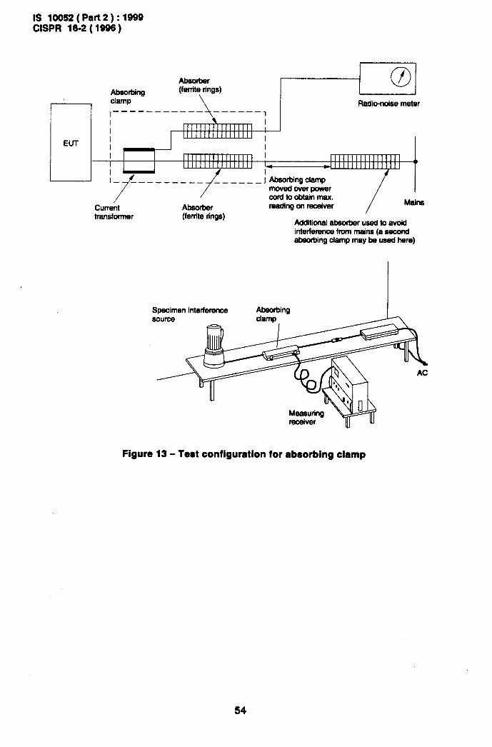
IS 10052(Prrt2):1999 CEPR 16-2 (1996)
Absorbing
1 clamp
Absorber (ferrite rings)
/ Current
/
Absorber
cordtoobtainmsx. reading on receiver /
Mains
transformer (ferrite rings) I
Addiional absorber used to avoid interference fmm mains (a second absorbing damp may be used here)
Specimen interference source
Figure 13 - Test configuration for absorbing clamp

IS 10952 ( Part 2 ) : 1999 CISPR 16-2 ( 1996 )
Receiving antenna
Supporting table
Groundplane
Figure 14 - Concept of electric field strength measurements made on an open area test site with the direct and reflective rays arriving at the receiving antenna (see 2.6.2.2)
55

IS 10052 ( Part 2 ) : 1999 CEPR 16-2 (1996)
Device under test Dipole A
Geometrtc centre
h h Measuring apparatus
.
7 ,,,,,,,,/ ,,,,5 ///// //J///////,L///// /,/,,,,,,
a) Measurement
d
Substltuhon dipole B
I 1
Srgnal generator - h
, 1
L 1 A Dipole A
b) Calibration
Figure 15 - Method of measurement - Substitution method (see 2.6.3.1 and 2.6.3.3)
56

IS 10052 ( Part 2) : 1999 CEPR 16-2 ( 1996 )
Coaxial switch
LJ
Measuring equipment ,
/ / /
. I Diameter: 2 m (3x)
l
F = ferrite absorber
c
Figure 16 - Concept of magnetic field induced current measurements made with the loop antenna system (see 2.6.5)
57

IS 10052 (Part2): 1999 CISPR 16-2 (1996)
Wanted signal generator (if applicable)
Direct coupling or radiation path EUT
Assessment of * EUT performance
!--- Monitoring path (visual or electrical)
Unwanted signal generator r
Figure 17 - Fundamental concept of immunity measurement (see 3.1 .l)
58

Coaxral cable, twisted parr or Other cables for mains, loud-speakers, - multr-lead cable - etc each terminated with a coupling
(screened or unscreened) unit (150 C)
L Equipment under test
Coupling unit Coupling unit
L Wanted signal generator or auxiliary ,
W
equipment
\
\
1 I
cn =+= 1Ocm
CD 7////////////P” I
////,~//////////////// ,,,/,,,,,/,,/,,,,,,,,,,,, /
L = isolating inductance C 1, C2 = capacitors with low RF
Interference RF signal generator
Rrnt + Rl - 1500
I =interfererice current
impedance (if ac.dc conditions allow this, capacitors should be replaced by a direct connection)
Figure 18 - General principle of the current-injection method (see 3.2)

IS 10052 ( Part 2 ) : 1999 CEPR 16-2 ( 1996 )
2 7
Unwanted signal generator Gl
Wanted signal generator G2
Load resistor RL
Low-pass filter (see annex 6)
Audio-frequency voltmeter (with weighting network
according to CCIR Recommendation 466)
Coupling network
Attenuators
Matching and/or balancing network
Equipment under test (EUT)
Figure 19 - Measuring set-up for input immunity measurement of sound broadcast receivers (see 3.2.3.1)
60

IS 10052 ( Part 2 ) : 1999 CEPR 16-2 ( 1996 )
6 7 6
.g 10
Unwanted signal generators Gl Wanted signal generators G2 Load resistor RL Low-pass filter Audio-frequency voltmeter (with weighting aetwork according to CCIR Recommendation 466) Coupling networks Attenuators Matching and/or balaacing network Equipment under test (EUT) Low-pass filter’
* To prevent influence of the measuring results by harmonics of the unwanted signal frequency
Figure 20 - Measuring set-up for input immunity measurement of television broadcast receivers (see 3.2.3.2)
61

IS 10052 ( Part 2 ) : 1999 CISPR 16-2 ( 1996 )
-
Screened room walls
b
E
‘4 5. I M
3
-_ccLc 0,15 m
6
p 3 f
I10 -.
11 I 7
.-. 3m.p. ‘A -. . E 1
t//
C9 I
c’
I 8 I
1
i g---r
1 tc 11: absorbing panels with dimensions of approximately 0.8 m x 0,4 m
Figure 21 - Example of the arrangement of an open stripline TEM device in combination with absorbing panels inside a screened room with dimensions 3 m x 3,5 m (see 3.3.1.1)
62

IS 10052 ( Part 2 ) : 1999 CEPR 16-2 ( 1996 )
Receiver under test
Ferrite toroids
Standard mput wanted signal
Figure 22 - Measuring set-up for the immunity of broadcast receivers to ambient fields in the frequency range of 0,15 MHz - 150 MHz (see 3.3.1.1)
63

IS 10052 ( Part 2 ) : 1999 CISPR 16-2 ( 1996 )
G2
Standard RF signal to receiver
c
--I-- l
I Gl
Sl Am F . . Inbferbg signal to TEM
D device via MN
-
Figure 23 - Measuring circuit for the immunity of sound broadcast reiceivers to ambient fiekls (see 3.3.1 .l .l)
64

Is 10052 (Part2 j : 1999 CISPR 16-2 ( 1996)
Annex A (informative)
Guidelines to connection of electrical equipment to the artificial mains network
(see 2.2)
A.1 Introduction
This annex is intended to give general guidance in the techniques which can be used to assess the disturbance generated by certain electrical equipment in the frequency range 9 kHz to 30 MHz. It provides information on methods of connection of such equipment to the artificial mains network for the measurement of terminal voltages. A table is provided giving a general presentation of various cases encountered in practice enabling, for such cases, a suitable technique to be selected.
The cases described below in A.2 identify propagation of the EUT disturbance either:
a) by conduction along the connected mains leads (designated with El and I1 in the
equivalent circuit diagrams), or
b) by radiation and coupled to the connected mains lead (designated with E2 and 12 in the
equivalent circuit diagrams).
Whether conducted or radiated disturbance dominates is partly dependent on the arrangement of the EUT with respect to the ground reference (including the type of connection to the reference ground) and of the type of connection from the EUT to the artificial mains network (shielded or non-shielded cable).
A.2 Classification of the possible cases
A.2.1 Well-shielded but poorly filtered EUT (figures A. 1 and A.2)
In this case, the conducted disturbance component represented by the current It dominates.
The disturbance current /A is fed from the EUT to the artificial mains network Z Consequently,
the voltage U1 increases when capacitance C1 between the EUT shield and the ground
reference increases (see figure A.l). The voltage U1 is maximized (Ul = Z/j = El) when the
impedance of the current return path is minimized by short-circuiting Cl either directly or
by using shielded cables to supply the EUT (see figure A.2). (Also, see the discussion in clause A.3.)
A.2.2 Well-filtered but incompletely shielded EUT (figures A.3 and A.4)
In this case, the disturbance current fed to the mains is reduced practically to zero, and the voltage across the artificial mains network may be dominated by undesirable radiation either from gaps in an incomplete shield or from a protruding conductor acting as an antenna. Such leakage can be represented schematically by an external capacitor C;! connected between an
internal disturbance source of e.m.f. E2 and ground reference. This capacitance C2 passes a
current 12. Part of the current 12 which flows through C;! to the ground reference returns via Cl
and a part of /2 returns via the artificial mains network. If the supply leads are unshielded
(figure A.3) and the impedance of Cl is large compared with the artificial mains impedance Z
(ZC, o <c l), then 1’2 is nearly equal to /2 and the voltage U2 is nearly equal to /2Z(U2 = Z/z).
If Cl is increased, Z is shunted and lJ2 will decrease. At the limit, when Cl is short-circuited
by supplying the EUT through shielded cables (figure A.4), so that no part of 12 flows through
Z, then U2 will be zero.
65

IS 10052 ( Part 2 ) : 1999 CISPR 16-2 ( 1996 )
A.2.3 Practical general case
Most usually in practices, neither the shielded nor the filtering are perfect; the two preceding effects then occur simultaneously and they are additive. In such conditions, the three following cases may be encountered.
A.2.3.1 Supply through shielded conductors (figure A.5)
The current II caused by leakage due to radiation flows in a circuit closed through ground and
the external surfaces of the screening of the artificial mains network and of the supply conductors; it has no effect on Z
The voltage U1, which may be measured across Z, is solely due to the current I1 injected into
the supply conductors and returning through the internal surfaces of the screening of the artificial mains network and these conductors. The voltage U1 is then maximum:
U1 = Zl, = El
A.2.3.2 Supply through unshielded but filtered conductors (figure A.6)
If a highly efficient low-pass fitter is connected to the input of the EUT, with its screening directly connected to the screening of the EUT, the current /I fed by source El to the mains
conductors will be stopped by the filter.
As in the case represented in figure A.6, the current 12 due to the radiation returns through Z
and the conductors (if ZC1 6.1 cc 1); the voltage U, measured across Zis then produced solely . .
by the radiation.
A.2.3.3 Supply through ordinary conductors (figure A. 7)
Should the filter in figure A.6 be removed, the current I1 from source El reappears on the
conductors (figure A.7). In comparison to figure A.5 (with the maximum possible value of 11 for
the supply of a non-filtered EUT through shielded conductors) the value of /I in figure A.7
(supply of a non-filtered EUT through ordinary i.e. unshielded conductors) is, if ZC1 w <c 1,
reduced to a minimum value in the ratio of /I (EUT unshielded) / /I (EUT shielded) = ZC1 w
referred to its minimum value (figure A.2). The current 12 is the same as in the previous cases,
but as the conductors are not shielded, it passes also through Zand the mains conductors.
The voltage U across the artificial mains network results then from the superposition of currents 11 and 12. When electromotive forces El and E2 are themselves produced by a
common internal source, these currents are synchronous and the voltage Udepends not only on their values but also on their phases. For certain frequencies, it may occur that currents It
and 12 are in opposition and if they are also of approximately the same magnitude, the voltage
U may become very small even if /I and 12 are individually quite large. Moreover, if the
frequency of the source varies, the phase opposition may not remain constant and voltage U may show rapid and considerable variations.
A.3 Method of grounding
In the foregoing, the connection to ground of the EUT was assumed to be made through connection of shielding of the supply conductors to the ground reference.
This is the only correct solution in order to obtain a grounding allowing a clear distinction between the two kinds of currents I1 and Q, as indicated above. It may be applied, without
exception to all frequencies.
66

IS 10052 ( Part 2 ) : 1999 CISPR 16-2 ( 1996 )
For frequencies below 1,6 MHz practically the same result may be achieved by grounding through a straight lead of small length (1 m maximum), running parallel to the mains lead and not more than 10 cm distant from it.
For frequencies above a few MHz, this simplified solution should only be used with care, especially at the higher frequencies. It is then strongly recommended that screened conductors be used in all cases. At the higher frequencies, it may be necessary to take into account the characteristic impedance of the conductor.
A.4 Conditions of grounding
A.4.1 General
A.4.1.1 General rules
It appears from the considerations discussed above that the behaviour of the measuring circuit for the voltage across the artificial mains network and, hence, the result of these measure- ments, is largely dependent on how the frame of the EUT being tested is connected to ground. It is therefore essential to specify these conditions closely.
Essentially, the principal effect of grounding is to separate the two currents It and 12 and
possibly to cause opposing variations of their respective actions on the measuring apparatus (which measures voltage U across 2). in the limiting case of a direct connection from the body of the EUT to ground, which short-circuits C,, the values of current I1 and thus of voltage
u1 = Z/l = El, are maximum; on the contrary, the current 12 due to radiation passes entirely
through this short circuit and the corresponding voltage U2 is reduced to zero.
From these remarks, the following general rules are drawn.
A.4 1.1.1 Direct grounding should always be used when testing:
a) a non-radiating EUT (e.g. a motor) as, in such a case, the measurement yields the maximum value of the disturbance voltage which may be met in practice;
b) a poorly filtered radiating EUT when, without troubling to measure the radiation, it is wished to measure solely the disturbance voltage due to direct injection into the supply conductors:
1) either for assessing the efficiency of the filter (for instance, for the time base circuits of television receivers);
2) or for assessing, in the laboratory, the actual disturbance produced by an apparatus whose radiation in normal operation will be suppressed by shielding (e.g. a transformer for the ignition system of fuel for boilers).
A.4.1.2 Direct grounding
Direct grounding should not be used when testing item 1) of A.4.1.1 .l either for a very well- filtered EUT which generates considerable radiation (for example, ozonizer, medical apparatus with damped oscillations, arc welders, etc.). In all these cases, the voltage across the artificial mains network becomes very small with direct grounding, while without such grounding the voltage may be quite large or unsteady. The measurement may then be meaningless and it may become necessary to make the grounding through a specified impedance in order to simulate the actual impedance of the safety ground (protective earth) conductor, e.g. by a protective ground choke which additionally provides some RF isolation from the “polluted” and therefore “poor” protective earth ground (see lower part of table A.2).
NOTE - The impedance of such an ‘electrical long’ conductor is in case of an EUT of safety protection Class I normally equal to the mains simulation impedance specified as termination for the mains terminals of the EUT provided by the artificial mains network (constituted by the network of 50 PH + 1 Q which, due to thermal problems in case of high current loads, may be reduced to a network of 50 pH).
67

IS 10052 ( Part 2 ) : 1999 CISPR 16-2 ( 1996 )
A.4.1.3 No grounding
Without any grounding, the voltage across the artificial mains network results from the addition of both currents /I and /2. A measurement can only be obtained when one of these currents:
is reduced to zero, either with a very well-screened shielded but poorly filtered EUT (e.g. a motor} or with a very well-filtered but radiating EUT (e.g. a television receiver, an ozonizer, etc.).
NOTE - If in case of an EUT of safety protection Class I for the purpose of analysis of 12. for the reduction of I1
the impedance according to the note under A.4.1.2 is not sufficient, a high impedance RF choke (1,6 mH) may be inserted into the ground conductor path.
The measurement usually yields only the value of the total disturbance, without allowing any discrimination, the results being only valid for the conditions used during the test. Such conditions should then be very well defined, namely the values of the capacitance to the ground plane of the various elements of the EUT (for instance, the capacitance of the transmission line from the aerial in the case of a television receiver). Moreover, a single measurement for one arbitrary frequency has no significance if, for this frequency, currents I1
and 12 are in opposition. As a matter of principle, then, it is necessary to make measurements
at a number of frequencies.
A.4.2 Classification of typical testing conditions
Tables A.1 and A.2 summarize the various testing conditions and the types of EUTs for which they are suitable. The tables also give the meaning of the measurement, that is, the physical quantity which corresponds to the voltage U measured across the artificial mains network Z and also the precautions to be taken when making the measurement.
68

1s 10052 ( Part 2) : 1999 CEPR 16-2 ( 1996 )
Table A.1 (see A.4.2)
Method of connection
Types of apparatus
- Quantity measured Details of the
Essential characteristics measurement Examples
Earthing Radiation Filtering
Motors Weak ModeratE Actual interference The interference Electro- domestic
(reduced) solely due depends on CI to injected current Cl
Arc-welding
Television
the superposition of the two preceding
gtrong Moderate effects (4 and IS)
receivers (time-base)
These two effects Measurement
(I, and /S) may be in should be repeated,
phase opposition at the frequency being
certarn frequencies varied
With Very Actual interference The position of the
good produced with an appliance with regard
earth connection of to earth should be
usual length specified in order that RC,- cl
Table A.2 (see A.4.2)
Method of connection Types of apparatus Quantity measured Examples
Details of the
measurement
when it is Ozonizers
desired to Arc-welding
measure only the inter- Transfoner for
ference Actual interference the ignition sys-
caused by caused by an tern of oil burners
current feed appliance which, in Part of a
to mains normal use, must be screened carefully screened assembly sep-
arately tested
Screened filter Poorly filtered
_ appliances when it is desired to measure only the inter- ference
7/////////////////f // caused by radiation
Television Check on the efficacy of the screening
receivers High- The position of the
frequency indus- trial apparatus
appliance with regard to earth
Actual interference should be caused by an appliance which, in normal use,
Fluorescent specified in
must be provided with lighting order that
a good filter zc,- <l
69

IS 10052 ( Part 2 ) : 1999 CEPR 16-2 ( 1996 )
EUT Artificial mains network
Screened cable
Figure A.1 (see A.2.1)
EUT Artificial mains network
‘I n n
I -
‘2 I 1 5)
4 6 Screened cable
I
=L, I
I T Cl
I / ///////////////////////////////////// _.
Figure A.2 (see A.2.1)

IS 10052(Part2):1999 CISPR 16-2 ( 1996 )
Filter EUT
J Artificial mains network
1; t
Figure A.3 (see A.2.2) Figure A.4 (see A.2.2)
EUT I 1 AMi&l mains network
4 _ I I
Figure A.5 (see A.2.3.1)
EUT Artificial mains network
Ordinary cable
Y---
4 .=+ G =G= c,
I -I //////////////////////////////,,j,,,,/
Figure A.6 (see A.2.3.2)
EUT Artificial mains network
Ordinary cable ‘I ) L
12 -5 6 7 1 I
=+G I G+= t , 1 7,/j ,,,,, ;, ,,,,
//////////////////////
Figure A.7 (see A.2.3.3)
71

IS 10052(Part2):1999 CEPR 16-2 (1996)
Annex f3 (informative)
Use of spectrum analyzers and scanning receivers (see clause 2.3)
i3.1 Introduction
When using spectrum analyzers and scanning measuring sets, the following characteristics should be taken into account:
B. 2 Overload
Most spectrum analyzers have no RF preselection in the frequency range up to 2000 MHz; that is, the input signal is directly fed to a broadband mixer. To avoid overload, to prevent damage and to operate a spectrum analyzer linearly, the signal amplitude at the mixer should typically be less than 150 mV peak. RF attenuation or additional RF preselection may be required to reduce the input signal to this level.
6.3 Linearity test
Linearity can be measured by measuring the level of the specific signal under investigation and repeating this measurement after an X dB attenuator has been inserted at the input of the
measuring set or, if used, the preamplifier (X 1 6 dt3). The new reading of the measuring set display should differ by X df3 not more than f 0,5 dB from the first reading when the measuring system is linear.
B. 4 Selectivity
The spectrum analyzer and scanning measuring set must have the bandwidth specified in ClSPR 16-l to correctly measure broadband and impulsive signals and narrowband disturbance with several spectrum components within the standardized bandwidth.
B. 5 Normal response t0 pulse8
The response of a spectrum analyzer and scanning measuring set with quasi-peak detection can be verified with the calibration test pulses specified in CEPR 16-1. The large peak voltage of the calibration test pulses typically requires an insertion of RF attenuation of 40 dB or more to satisfy the linearity requirements. This decreases the sensitivity and makes the measurement of low repetition rate and isolated calibration test pulses impossible for bands B, C and D. If a preselecting filter is used ahead of the measuring set, then the RF attenuation can be decreased. The filter limits the spectrum width of the calibration test pulse as seen by the mixer.
B. 6 Peak detection
The normal (peak) detection mode of spectrum analyzers provides a display indication which, in principal, is never less than the quasi-peak indication. It is convenient to measure emissions using peak-detection because it allows faster frequency scans than quasi-peak detection. Then those signals which are close to the emission limits need to be remeasured using quasi- peak detection to record quasi-peak amplitudes.
B. 7 Frequency 8C8n rate
The scan rate of a spectrum analyzer or a scanning measuring set should be adjusted for the CEPR frequency band and the detection mode used. The minimum sweep time/frequency or the fastest scan rate is listed in the following table:
72

IS 10052 ( Part 2 ) : 1999 CISPR 16-2 ( 1996 )
I Band I Peak-detection I Quasi-peak detection I
A 100 ms/kHz
B 100 ms/ MHz
20 s/kHz
200 s/ MHz
I C&D I 1 ms/MHz I 20 s/MHz I
For a spectrum analyzer or scanning measuring set used in a fixed tuned non-scanning mode, the display sweep time may be adjusted independently of .the detection mode and according to the needs for observing the behaviour of the emission. If the level of disturbance is not steady, the reading on the measuring set must be observed for at least 15 s to determine the ‘maximum (see 2.3.4.1).
9.8 Signal interception
The spectrum of intermittent emissions may be captured with peak-detection and digital display storage if provided. Multiple, fast frequency scans reduce the time to intercept an emission compared to a single, slow frequency scan. The starting time of the scans should be varied to avoid any synchronism with the emission and thereby hiding it. The total observation time for a given frequency range must be longer than the time between the emissions. Depending upon the kind of disturbance being measured, the peak detection measurements can replace all or part of the measurements needed using quasi-peak detection. Re-tests using a quasi-peak detector should then be made at frequencies where emission maxima have been found.
., 9.9 Average detection
Average detection with a spectrum analyzer is obtained by reducing the video bandwidth until no further smoothing of the displayed signal is observed. The sweep time must be increased with reductions in video bandwidth to maintain amplitude calibration. For such measurements, the measuring set shall be used in the linear mode of the detector. After linear detection is made, the signal may be processed logarithmically for display, in which case the value is corrected even though it is the logarithm of the linearly detected signal.
A logarithmic amplitude display mode may be used, for example, to distinguish more easily between narrowband and broadband signals. The displayed value is the average of the logarithmically distorted IF signal envelope. It results in a larger attenuation of broadband signals than in the linear detection mode without affecting the display of narrowband signals. Video filtering in log-mode is, therefore, especially useful for estimating the narrowband component in a spectrum containing both.
9.10 Sensitivity
Sensitivity can be increased with low noise RF pre-amplification ahead of the spectrum analyzer. The input signal level to the amplifier should be adjustable with an attenuator to test the linearity of the overall system for the signal under examination.
The sensitivity to extremely broadband emissions which require large RF attenuation for system linearity is increased with RF pre-selecting filters ahead of the spectrum analyzer. The filters reduce the peak amplitude of the broadband emissions and less RF attenuation can be used. Such filters may also be necessary to reject or attenuate strong out-of-band signals and the intermodulation products they cause. If such filters are used they must be calibrated with broadband signals.
9.11 Amplitude accuracy
The amplitude accuracy of a spectrum analyzer or a scanning measuring set may be verified by using a signal generator, power meter and precision attenuator. The characteristics of these instruments, cable and mismatch losses have to be analyzed to estimate the errors in the verification test.
73

IS 10052 ( Part 2 ) 3999 CEPR 16-2 ( 1996 )
Annex C (informative)
Historical background to the method of measurement of interference power produced by electrical household
and similar appliances in the VHF range (see clause 3.1)
the
C.l Historical detail
Although measurement of field strength is, in theory, the most suitable for determining the interference capability of all types of appliances at frequencies higher than 30 MHz, the methods involved together with the precautions to be taken prove troublesome in application. Consequently, engineers have for a long time used the terminal voltage method, while waiting for something more satisfactory. Several methods have been envisaged to replace those involving field measurements in open air by radiation measurements in the laboratory. Among the most interesting are the stop filter method and the ground current method. These are substitution methods, in which a slotted coaxial filter having negligible losses is used to adjust the radiating length of the supply lead of the source of interference in such a way as to obtain maximum radiation. In these methods, the interference capability of an appliance is defined as the power which a standard generator must inject into a simple aerial of known characteristics in order to obtain the same effect on an aerial connected to the measuring apparatus as that produced by the source of interference. Several more convenient methods have been developed from those just mentioned.
The measurement of terminal voltages has been considerably improved by replacing the artificial mains V-network by a Y-network, so as to obtain the true common mode voltage produced by the source of interference. A similar method using a reactive slotted coaxial filter was developed. A method for measuring the power which the source of interference may inject into the supply lead has also been proposed. This method is based on the measurement of the current at the input of an absorbent coaxial device.
The advantage of the latter over the terminal voltage method is that it is not necessary to disconnect the supply lead. It indicates values of the interference power corresponding closely with those obtained by the methods in which the radiation of the supply lead is measured in the resonant condition.
Although, through their ease of operation, the terminal voltage and the absorbing coaxial device methods were preferable to the stop filter and the ground current methods, it remained to be shown that the results which they gave conformed with those obtained in practice.
Statistical measurements on the disturbance sources have shown that the interference measured by the stop filter method agrees more closely than that measured by the terminal voltage method, with the effect of the same sources measured at the input of receivers located in the same building. Measurements made by the absorbent device method gave results intermediate between the two previous ones. Other methods have been compared.
C.2 Development of the method
In the stop filter method, a value directly related to the current at the centre of a resonant half- wave aerial is measured. The most important thing is not the radiating system but the power that the source of interference is capable of transmitting to the radiating system. The same principle applies to the ground current method. If it were possible to measure this power without measuring a field, all the disadvantages arising from the influence of surrounding objects on the propagation between the radiating elements and the receiving aerial would be removed. The attempt to replace the coaxial stop filter by a ferrite tube showed that a large
74

IS 10052 ( Part 2 ) : 1999 CEPR 16-2 (1996)
part of the energy produced by the source of interference was dissipated in this tube. It was then thought that the measurement of the current at the input of the ferrite tube might replace, at least in part, the measurement of the field by the stop filter method. This gave rise to the devices described in annex K of CISPR 16-l.
The following question was then studied: how do the different methods of measurement compare in the particular case of a shielded source of interference of given available power, with a purely resistive internal impedance when transmitting all its interference energy to the supply lead in the common mode when the size of this source is varied? Experimental investigations showed the remarkable fact that the new device gave results which were practically independent of the dimensions of the source of interference (35 dm3 to 1700 dm3) and which were also more consistent than those obtained by other methods.
In fact, one can reduce the absorbing device measuring system to the following circuit: a source of interference of internal impedance Zs supplying a load Zc through a low-loss line of
characteristic impedance ZL. If the length of the line is varied from zero, the power absorbed
by the load Zc passes (when Zc is different from ZL) through maxima and minima
corresponding to resonance and anti-resonance of the system.
Neglecting the radiation and other losses of the line and discussing the case in which the load is located at a distance corresponding to the first maximum, we consider the point in the line at which the source and the load appear as pure resistance Rs and Rc. It can thus be shown that
if Pd is the available power of the source, PC the power absorbed by the load and
then
P 4m
$= (m+1j2
This gives for
m= 0,l
M=lOlg:= = -4,8 pd
0,2 0,5 1 2 5 10 20 30
-2,5 -0,5 0 -0,5 -2,5 -4,8 -7,4 -9 dB
It will be seen that the matching of the source to the lead is not very critical and that, if an
absorbent clamp is used to constitute a load, for example of the order of 200 R, the results obtained will not be very different from those obtained if a load is applied to the output of the source of interference in the form of a line brought to resonance by means of a coaxial stop filter.
75

( Continued from second cower)
International Standard Corresponding Indian Standard Degree of Equivalence
CISPR 14 ( 1993 ) Limits and IS 6873 ( Part 2 ) : 1999 Limits and methods Identical methods of measurementof radio of measurement of radio disturbance disturbance characteristics of characteristics : Part 2 Electric motor-operated electrical motor-operated and and thermal appliances for household and thermal appliances for household similar purposes, electrical tools and elec- and similar purposes, electric tric apparatus ( first revision) tools and electric apparatus
CISPR 16-1 ( 1993 ) Specification IS 10052 ( Part 1 ) : 1999 Specification for do for radio disturbance and radio disturbance and immunity measuring immunity measuring apparatus apparatusand methods : Part 1 Radiodisturb- and methods - Part 1 : Radio- ante and immunity measuring apparatus disturbance and immunity ( first revision ) measuring apparatus
The concerned Technical Committee responsible for the preparation of this standard has reviewed the provisions of the following International Publication and has decided that it is acceptable for use in conjunc- tion with this standard.
ITU-R 468 : Measurement of audio-frequency noise voltage level in sound broadcasting
Only the English language text of the International Standard has been retained while adopting it in this Indian Standard.

Bureau’bf Indian Standards
BIS is a statutory institution established under the Bureau ofhdian Standards&t, 1986 to promote harmonious development of the activities of standardization, marking and quality certiflmtion of goods and attending to connected matters in the country.
Copyright
BIS has the copyright of all its publications. No part of these publications may be reproduced in any form without the prior permission in writing of BIS. This does not preclude the free use, in the course of implementing the standard, of necessary details, such as symbols and sizes, type or grade designations. Enquiries relating to copyright be addressed to the Director (Publications), BIS.
Review of Indian Standards
Amendments are issued to standards as the need arises on the basis of comments. Standards are also reviewed periodically; a standard along with amendments is reaffirmed when such review indicates that no changes are needed; if the review indicates that changes are needed, it is taken up for revision. Users of Indian Standards should ascertain that they are in possession of the latest amendments or edition by referring to the latest issue of ‘BIS Handbook’ and ‘Standards : Monthly Additions’.
This Indian Standard has been developed from Dot : No. LTD 22 ( 1835 ).
Amendments Issued Since Publication
Amend No. Date of Issue Text Affected
Headquarters :
BUREAU OF INDIAN STANDARDS
Manak Bhavan, 9 Bahadur Shah Zafar Marg, New Delhi 110002 Telephones : 323 01 31,323 94 02, 323 33 75
Telegrams: Manaksanstha ( Common to
all offices )
Regional Offices: Telephone
Central : Manak Bhavan, 9 Bahadur Shah Zafar Marg 323 76 17 NEW DELHI 110002 323 3841
Eastern : l/14 C. I. T. Scheme VII M, V. I. P. Road, Maniktola 337 84 99, 337 85 61 CALCUTTA 700054 337 86 26, 337 86 62
Northern : SC0 335-336, Sector 34-A, CHANDIGARH 160022 1 60 38 43 60 20 25
Southern : C. I. 7 Campus, IV Cross Road, CHENNAI 600113 23502 16,2350442 235 15 19,235 23.15
Western‘: Manaka?aya, E9 MIDC, Marol, Andheri (East) MUMBAI 400093 I
8329295,8327858 8327891,8327892
Branches : AHMADABAD. BANGALORE. BHOPAL. BHUBANESHWAR. COIMBATORE. FARIDABAD. GHAZIABAD. GUWAHATI. HYDERABAD. JAIPUR. KANPUR. LUCKNOW. NAGPUR. PATNA. PUNE. THIRUVANANTHAPURAM.
Printed at New India Printing Press, Khuja, India