Embed Size (px)
Citation preview
EDITION: 1 SANCTION DATE: November 17, 2020
IRP 26: Wellbore Remediation An Industry Recommended Practice (IRP) for the Canadian Oil and Gas Industry
Volume 26 – 2020


Copyright/Right to Reproduce
Copyright for this Industry Recommended Practice is held by Energy Safety Canada,
2020. All rights reserved. No part of this IRP may be reproduced, republished,
redistributed, stored in a retrieval system, or transmitted unless the user references the
copyright ownership of Energy Safety Canada.
Disclaimer
This IRP is a set of best practices and guidelines compiled by knowledgeable and
experienced industry and government personnel. It is intended to provide the operator
with general advice regarding the specific topic. It was developed under the auspices of
the Drilling and Completions Committee (DACC). IRPs are provided for informational
purposes. Users shall be fully responsible for consequences arising from their use of
any IRP.
The recommendations set out in this IRP are meant to allow flexibility and must be used
in conjunction with competent technical judgment. It is recognized that any one practice
or procedure may not be appropriate for all users and situations. It remains the
responsibility of the user of this IRP to judge its suitability for a particular application and
to employ sound business, scientific, engineering and safety judgment in using the
information contained in this IRP.
If there is any inconsistency or conflict between any of the recommended practices
contained in this IRP and an applicable legislative or regulatory requirement, the
legislative or regulatory requirement shall prevail. IRPs are by their nature intended to
be applicable across industry, but each jurisdiction may have different or unique legal
requirements. Users of this IRP should consult with authorities having jurisdiction.
Users are advised to consider if their operations or practices and this IRP comply with
the legal requirements in any particular jurisdiction in which they operate.
Every effort has been made to ensure the accuracy and reliability of the data and
recommendations contained in this IRP. However, DACC, its subcommittees, individual
contributors and affiliated persons and entities make no representation, warranty, or
guarantee, either express or implied, with respect to the accuracy, completeness,
applicability or usefulness of the information contained in any IRP, and hereby disclaim
liability or responsibility for loss or damage resulting from the use of this IRP, or for any
violation of any legislative, regulatory or other legal requirements.
IN NO EVENT SHALL DACC, ENERGY SAFETY CANADA, ANY SUBMITTING
ORGANIZATION NOR ANY OF THEIR EMPLOYEES, DIRECTORS, OFFICERS,
CONTRACTORS, CONSULTANTS, COMMITTEES, SUBCOMMITTEES,
VOLUNTEERS, OR OTHER AFFILIATED OR PARTICIPATING PERSONS BE LIABLE
Wellbore Remediation Table of Contents
TO OR RESPONSIBE FOR ANY PERSON USING AN IRP OR ANY THIRD PARTY
FOR ANY DIRECT, INDIRECT, INCIDENTAL, SPECIAL OR CONSEQUENTIAL
DAMAGES, INJURY, LOSS, COSTS OR EXPENSES, INCLUDING BUT NOT LIMITED
TO LOST REVENUE OR GOODWILL, BUSINESS INTERRUPTION, OR ANY OTHER
COMMERCIAL OR ECONOMIC LOSS, WHETHER BASED IN CONTRACT, TORT
(INCLUDING NEGLIGENCE) OR ANY OTHER THEORY OF LIABILITY. This exclusion
shall apply even if DACC has been advised or should have known of such damages.
Availability
This document, as well as future revisions and additions, is available from
Energy Safety Canada
Unit 150 – 2 Smed Lane SE
Calgary, AB T2C 4T5
Phone: 1 800 667 5557
Website: www.energysafetycanada.com

Table of Contents Wellbore Remediation
October 2020
i
Table of Contents
26.0 Preface ...................................................................................................... v
Purpose ......................................................................................................... v
Audience ....................................................................................................... v
Scope and Limitations ................................................................................. v
Revision Process ......................................................................................... v
Sanction ....................................................................................................... vi
Acknowledgements ..................................................................................... vi
Range of Obligations ................................................................................. vii
Background ................................................................................................ vii
26.1 Introduction .............................................................................................. 1
26.2 Job Types ................................................................................................. 3
Objectives ..................................................................................................... 3
Groundwater Protection .............................................................................. 3
SCVF/GM Repair ........................................................................................... 4
Porous Zone Isolation .................................................................................. 4
Water or Gas Shutoff and Injector Conformance ....................................... 5
Completion Interval Isolation ...................................................................... 5
Casing Repair ............................................................................................... 5
26.2.7.1 Cement Squeeze.................................................................................. 6
26.2.7.2 Slim Hole Casing .................................................................................. 6
26.2.7.3 Mechanical Casing Repair .................................................................... 7
26.3 Input Data Analysis .................................................................................. 9
Review of Open/Cased Hole Logs ............................................................. 10
Cement Top Determination ........................................................................ 10
Groundwater Depth .................................................................................... 11
Porous Zone Isolation ................................................................................ 12
Water or Gas Shutoff and Injector Conformance ..................................... 12
Completion Interval Isolation .................................................................... 12
Casing Repair ............................................................................................. 13
26.4 Technique Selection for Remedial Cementing .................................... 15

Wellbore Remediation Table of Contents
October 2020 ii
Access ........................................................................................................ 15
26.4.1.1 Perforations ........................................................................................ 15
26.4.1.2 Abrasive Jetting .................................................................................. 16
26.4.1.3 Mechanical Perforators ...................................................................... 16
26.4.1.4 Existing Access Point ......................................................................... 16
26.4.1.5 Section Milling .................................................................................... 16
Wellbore Preparation ................................................................................. 16
26.4.2.1 With Circulation .................................................................................. 17
26.4.2.2 Without Circulation ............................................................................. 17
Application and Conveyance .................................................................... 18
Treatment .................................................................................................... 19
Placement ................................................................................................... 20
26.4.5.1 Squeeze Through a Retainer ............................................................. 21
26.4.5.2 Squeeze With a Packer ...................................................................... 21
26.4.5.3 Bradenhead Squeeze ......................................................................... 22
26.4.5.4 Bullhead Squeeze .............................................................................. 22
26.5 Technique Selection for Mechanical Casing Repair ........................... 23
Wellbore Access ........................................................................................ 23
26.5.1.1 Swedging ........................................................................................... 24
26.5.1.2 Milling ................................................................................................. 24
Internal Patches ......................................................................................... 25
26.5.2.1 Wellbore Preparation .......................................................................... 26
26.5.2.2 Retrievable Patches ........................................................................... 26
26.5.2.3 Non-Retrievable Patches .................................................................... 28
Structural Support Liner ............................................................................ 30
Casing Replacement .................................................................................. 31
External Patches ........................................................................................ 32
26.6 Material(s) Selection .............................................................................. 35
Cement ........................................................................................................ 35
Spacer ......................................................................................................... 35
Alternatives to Cement .............................................................................. 36
26.7 Job Execution ......................................................................................... 37
Field Procedures ........................................................................................ 37
Quality Assurance ...................................................................................... 37

Table of Contents Wellbore Remediation
October 2020
iii
Contingency Plans ..................................................................................... 38
26.8 Post-Job Evaluation ............................................................................... 39
Cement Sample Evaluation ....................................................................... 39
Groundwater Protection ............................................................................ 39
Porous Zone Isolation ................................................................................ 40
26.8.3.1 Circulation .......................................................................................... 40
26.8.3.2 Multiple zone isolation ........................................................................ 40
Water or Gas Shutoff and Injection Conformance ................................... 40
Completion Interval Isolation .................................................................... 40
Casing Repair ............................................................................................. 41
26.8.6.1 Cement Squeeze................................................................................ 41
26.8.6.2 Slim Hole Casing ................................................................................ 41
26.8.6.3 Mechanical Casing Repair .................................................................. 41
Appendix A: Revision Log ............................................................................... 43
Appendix B: Glossary ...................................................................................... 45
Appendix C: References and Resources ........................................................ 49
List of Tables
Table 1. Development Committee ............................................................................... vi
Table 2. Range of Obligation ...................................................................................... vii
Table 3. Access Techniques by Job Type ................................................................. 15
Table 4. Techniques to Gain Circulation or Increase Feed Rate .............................. 18
Table 5. Techniques to Complete Remedial Squeeze Cementing ........................... 19
Table 6. Placement Method by Job Type .................................................................. 20
Table 7. Pros and Cons of Retainer Squeezes .......................................................... 21
Table 8. Pros and Cons of Packer Squeezes ............................................................. 21
Table 9. Pros and Cons of Bradenhead Squeezes .................................................... 22
Table 10. Pros and Cons of Bullhead Squeezes ....................................................... 22
Table 11. Swedging Pros and Cons ........................................................................... 24
Table 12. Milling Pros and Cons ................................................................................. 25
Table 13. Retrievable Patch Pros and Cons .............................................................. 27
Table 14. Non-Retrievable Patch Pros and Cons ...................................................... 29

Wellbore Remediation Table of Contents
October 2020 iv
Table 15. Casing Replacement Pros and Cons ......................................................... 31
Table 16. External Patch Pros and Cons ................................................................... 33
Table 17. Revisions Summary .................................................................................... 43

Preface Wellbore Remediation
October 2020
v
26.0 Preface
Purpose
The purpose of this document is to provide best practices to perform efficient, long-
lasting wellbore remediation while mitigating adverse impacts to the environment and
protecting groundwater.
Audience
The intended audience for this document is personnel involved in the planning and
execution of wellbore remediation activities. It is assumed that the reader has at least a
journeyman level of understanding of the concepts and processes involved in wellbore
remediation.
Scope and Limitations
The scope of IRP 26 includes methodologies to repair/modify a land-based petroleum
industry wellbore back to its intended use or for wellbore decommissioning (as per IRP
27: Wellbore Decommissioning). The objectives of the repair include re-establishing
wellbore integrity and/or ensuring hydraulic isolation between porous intervals. Key
remediations discussed include base of groundwater protection, surface casing vent
flow and/or gas migration repair, porous zone isolation, water or gas shutoff and injector
conformance and casing repair using a squeeze or slim hole casing.
The scope of IRP 26 does not include problem identification except in the sense that
remediation can be an iterative process that identifies new problems as it resolves old
ones. It is assumed that the initial remediation required has already been identified.
Revision Process
IRPs are developed by the Drilling and Completions Committee (DACC) with the
involvement of both the upstream petroleum industry and relevant regulators. Energy
Safety Canada acts as administrator and publisher.
Technical issues brought forward to the DACC, as well as scheduled review dates, can
trigger a re-evaluation and review of this IRP in whole or in part. For details on the IRP
creation and revisions process, visit the Energy Safety Canada website at
www.EnergySafetyCanada.com.

Wellbore Remediation Preface
October 2020 vi
A complete list of revisions can be found in Appendix A.
Sanction
The following organizations have sanctioned this document:
Canadian Association of Oilwell Drilling Contractors (CAODC)
Canadian Association of Petroleum Producers (CAPP)
Petroleum Services Association of Canada (PSAC)
Explorers & Producers Association of Canada (EPAC)
Acknowledgements
The following individuals helped develop IRP 26 through a subcommittee of DACC.
Table 1. Development Committee
Name Company Organization Represented
Dwayne Cooper (Co-chair)
Performance Energy CAODC
Leah Davies (Co-Chair) Imperial Oil Resources CAPP
Afshin Ahmady Halliburton PSAC
Gerry Boyer InnoTech Alberta SME
Mitch Brekko Husky Energy CAPP
Dale Duffy Canadian Natural Resources Ltd. CAPP
Gary Ericson Government of Saskatchewan Regulator
Shawn Forster Husky Energy CAPP
George Humphrys NL Fisher Supervision and Engineering
CAODC
Ken Masich AER Regulator
Ian McConnell Energy 37 Consulting Inc. PSAC
Malcolm McKean Elm Inc. PSAC
Jeff Spence Sanjel Energy Services PSAC
Noal Swanson CNRL CAPP
Blair Temple Imperial Oil Resources CAPP
Jordan Van Besouw BCOGC Regulator
Nathan White Sanjel Energy Services PSAC
Sarah Whitton Schlumberger Canada Ltd. PSAC
Colin Witt Stingray Well Solutions SME

Preface Wellbore Remediation
October 2020
vii
Name Company Organization Represented
Casing Repair Subcommittee
Bernie Jones (co-chair) Core Lab Reservoir Optimization PSAC
Blair Temple (co-chair) Imperial Oil Resources CAPP
Mitch Brekko Husky Energy CAPP
Matt Dagert Treeline Well Services LP CAODC
Rob St. Martin Canadian Natural Resources Ltd. CAPP
Jamie Petrovic Schlumberger Canada Ltd. PSAC
Colin Witt Stingray Well Solutions SME
Range of Obligations
Throughout this document the terms ‘must’, ‘shall’, ‘should’, ‘may’ and ‘can’ are used as
indicated below:
Table 2. Range of Obligation
Term Usage
Must A specific or general regulatory and/or legal requirement that must be followed. Statements are bolded for emphasis.
Shall An accepted industry practice or provision that the reader is obliged to satisfy to comply with this IRP. Statements are bolded for emphasis.
Should A recommendation or action that is advised.
May An option or action that is permissible within the limits of the IRP.
Can Possibility or capability.
Background
The DACC Primary and Remedial Cementing Guidelines was published in April of 1995.
It contained high level guidelines about performing primary and remedial cement jobs.
In 2015 a committee was formed to perform a full scope review of the Primary and
Remedial Cementing Guidelines and create IRP 25 with the content. The development
committee determined that remedial cementing needed to be addressed separately from
primary cementing so IRP 25 was written to cover only primary cementing. It provides
extensive detail on planning, executing and evaluating a primary cement job. IRP 25:
Primary Cementing was sanctioned in January 2017.

Wellbore Remediation Preface
October 2020 viii
In 2017 DACC struck a new committee to address remedial cementing as IRP 26. The
scope was expanded to include all wellbore remediation, including the use of pumpable
products other than cement (i.e., alternate products – see Appendix B: Glossary for a
description).
During their work on IRP 26, the IRP 26 committee determined that casing repair, other
than squeezes and use of slim hole casing, required a different expertise than the
operators and cementing service providers that made up the current committee. DACC
struck a Casing Repair subcommittee in September of 2019 to generate content. This
content was incorporated into the document during the initial industry review of IRP 26
for review during final industry review.
The IRP 26 committee also determined that source identification and remediation for
surface casing vent flows and gas migration required different expertise. DACC agreed
to address these topics topic in IRP27: Wellbore Decommissioning and the applicable
sections are referenced from IRP 26 rather than duplicated. IRP 27 is expected to be
published in draft form for industry review in Q1 2021.

Introduction Wellbore Remediation
October 2020
1
26.1 Introduction
This document contains recommended practices to re-establish wellbore integrity and/or
ensure hydraulic isolation between porous intervals. This IRP assumes that the type of
remediation required has already been identified either through regulatory
requirement(s) or existing well information. It does not discuss problem identification
techniques other than those used for information gathering.
The IRP discusses the data analysis, job design (i.e., technique selection and material
selection), job execution and post-job evaluation of the following remediations (job
types):
• Groundwater Protection
• Surface Casing Vent Flow (SCVF) and/or Gas Migration (GM) Repair
• Porous Zone Isolation
• Water or Gas Shutoff and Injector Conformance
• Completion Interval Isolation
• Casing Repair
Job design and execution is an iterative process of information gathering, data analysis,
job (or step) design and execution. If any of the data required to design the job is
missing it may be necessary to design and execute a limited scope job to gather the
required information before proceeding with the next stage of analysis and design.
Data analysis includes identification of what information is required, what is available
and what is missing. This document includes recommendations about the techniques
that can be used to gather and analyze data.
Job design includes technique and materials selection with recommendations about
access, wellbore preparation, application and conveyance, treatment(s), placement,
cement, spacers and considerations for the use of alternatives to cement.
Job execution includes field procedures, quality assurance and contingency planning.
Post-job evaluation discusses the techniques to verify job objectives.

Wellbore Remediation Introduction
October 2020 2
General cementing practices are covered in IRP 25: Primary Cementing. This IRP
covers only cementing considerations and practices specific to remediation work that
are not already covered in IRP 25.
This IRP focuses primarily on remedial work with cement but recognizes there may be
alternatives to cement for some operations. Where cement is indicated it is up to the job
designer to determine whether an alternative could be used and the implications for use.

Job Types Wellbore Remediation
October 2020
3
26.2 Job Types
It is possible for there to be more than one remediation required or for one remediation
to identify or introduce an additional problem. Remedial operations typically begin at the
lowermost interval in the wellbore and progress upwards to the shallowest interval.
IRP An assessment of the physical location and current well condition should be
completed as part of planning.
Objectives
The objective(s) of wellbore remediation can be one or more of the following:
• Restore casing integrity
• Provide hydraulic isolation behind casing
• Provide hydraulic isolation inside casing
• Provide hydraulic isolation in an uncased wellbore
• Provide a permanent well integrity solution
Groundwater Protection
Distinct sources of non-saline groundwater need to be isolated from each other and
from hydrocarbon-bearing zones. The depth at which this groundwater occurs is
referred to as the Base of Groundwater Protection (BGWP) in Alberta and the Base of
Usable Groundwater (BUGW) in British Columbia (see Appendix B: Glossary). For
purposes of IRP 26 this depth will be referred to as BGWP.
Groundwater intervals are defined by local jurisdictional regulations (e.g., AER Directive
020: Well Abandonment, BCOGC Drilling and Production Regulation).
IRP Groundwater intervals must be identified and isolated as per local
jurisdictional regulations.
IRP If all required intervals are not isolated, each interval for remedial
operations must be identified (e.g., as per AER Direction 020: Well
Abandonment section 5.5 Groundwater Protection).
If cemented surface casing covers all groundwater intervals the groundwater is deemed
to be protected and BGWP remediation may not be required.

Wellbore Remediation Job Types
October 2020 4
IRP BGWP remediations should be performed prior to setting the next casing string
or liner.
Consider identifying BGWP depth prior to any remedial operations outside casing as
there may be an opportunity to isolate groundwater concurrently.
SCVF/GM Repair
SCVF/GM repairs are required in cases where liquid or gas flow reach surface in the
surface casing or near the wellhead.
IRP The local jurisdictional regulations regarding the categorization (i.e.,
serious or non-serious) and remediation of SCVFs or GM must be followed
(e.g., AER ID2003-01).
IRP SCVF/GM classified as serious must be disclosed to the regulator within 30
days and remediated on an agreed timeline, usually within 90 days of
discovery.
SCVF/GM categorized as non-serious may be deferred to time of decommissioning.
SCVF/GM repairs typically require through-casing access similar to BGWP and porous
zone isolation work to place cement (or alternate product) outside casing and provide
hydraulic isolation. In the event these repairs are required prior to the end of the well’s
producing life, Additional steps may be required to drill out the repair intervals, confirm
pressure integrity of the repair intervals and provide access for production equipment.
Local jurisdictional regulators have criteria for notification when the flow characteristics
significantly change.
IRP Local jurisdictional regulations must be followed for reporting SCVF and
GM.
Refer to the SCVF/GM Source Identification and Remediation sections of IRP 27:
Wellbore Decommissioning for details about determining the source, remediation and
post-job evaluation of SCVF/GM.
Porous Zone Isolation
Porous zone isolation jobs are required at the time of decommissioning when well
construction did not provide hydraulic isolation across porous intervals. This type of job
can also be required on new wells where primary cementing does not provide the
required coverage.

Job Types Wellbore Remediation
October 2020
5
Water or Gas Shutoff and Injector Conformance
Workovers can be required to modify production or injection profiles. Workovers can
also be required to ensure injected fluids are contained within the desired injection zone.
Remedial cementing or pumping of alternative products is typically performed as part of
these jobs.
These jobs are often accomplished by isolating part of the completion intervals inside
the wellbore with mechanical plugs, cement plugs or alternate product plugs. Cement or
alternate products are pumped outside the casing to help close off any pathways in the
cement sheath or near wellbore region. If intervals are small, the entire completion
interval may be cemented off and a portion then re-accessed.
Completion Interval Isolation
The most common technique for isolating a completion interval is to set a bridge plug
above the completed interval then place cement or an alternate product on top of the
plug. In cases where a mechanical plug can’t be placed above the interval, isolation
may be achieved with a cement plug alone. In some cases, a cement retainer is set
above the interval and the interval is then squeezed off. Well-specific techniques need
to consider current wellbore condition, long term plans and regulatory requirements,
particularly for long term decommissioning of an interval.
Casing Repair
The following typically identify the need for a casing repair operation:
• A failed wellbore pressure test or a well on vacuum on the annulus side.
• The inability to pull bottom hole equipment.
• The inability to run bottom hole tools (e.g., packers, bridge plugs, anchors, pumps, etc.).
Use the appropriate tools to identify the following:
• Problem location and size.
• Nature of the problem (i.e., deformation, restriction, collapse or breach).
• Cause of problem (e.g., seismic event, fracturing induced, thermal event, etc.).
• Casing condition (e.g., corrosion).

Wellbore Remediation Job Types
October 2020 6
These tools may include the following:
• Tubing/packer arrangement to confirm top and bottom of leaking section.
• Video camera units (requires effective hole conditioning for clear viewing).
• Gauge rings.
• Casing inspection logs. Electromagnetic and ultrasonic tools can provide indications of internal and external wall loss. Through tubing logs can provide some information on casing condition.
• Casing caliper log.
• Lead impression block.
• A cement evaluation log to determine cement quality if split casing is a concern. This can identify whether the interval to seal is supported or unsupported.
If wellbore access is restricted by a casing issue it may be necessary to regain access
before the repair can be completed (see 26.5.1 Wellbore Access).
IRP All casing failures must be reported to the local jurisdictional regulator.
Refer to the following for more information about the regulations pertaining to casing
repair:
• AER ID 2003-01: 1) Isolation Packer Testing, Reporting, and Repair Requirements; 2) Surface Casing Venting Flow/Gas Migration Testing, Reporting, and Repair Requirements; 3) Casing Failure Reporting and Repair Requirements.
• AER Bulletin 2009-07: Revisions to the Digital Data Submission System Regarding Interim Directive 2003-01.
• Saskatchewan PNG015: Well Abandonment Requirements.
26.2.7.1 Cement Squeeze
Remedial cementing can be used to restore casing pressure integrity, most typically for
non-thermal operations, both in-zone and above producing intervals. The leaking
interval is squeeze cemented, then drilled out and pressure tested after cement has set.
Note: An alternative to cement may be used. See 26.6 Material(s)
Selection for more information.
26.2.7.2 Slim Hole Casing
If cement alone is not expected to provide sufficient long-term integrity, a smaller slim
hole casing string can be cemented inside the larger casing string. This is a common
repair technique for thermal wells. The slim hole string is typically run from surface to a
point just above the completion interval. This provides a uniform inner diameter for

Job Types Wellbore Remediation
October 2020
7
future operations and a secure tie in to the existing wellhead or a new wellhead for long
term pressure integrity.
Slim hole casing can, in some cases, inhibit access and cause restrictions for well
integrity investigation and remediation.
IRP If slim hole casing is to be used a complete well review should be conducted to
ensure any other well integrity issues are identified (e.g., BGWP, porous zone
isolation, GM, SCVF, etc.).
Achieving zero free water is key to successful cementing of slim hole casing in thermal
applications. Refer to the Slurry Design section IRP 25: Primary Cementing for more
information about free water and other slurry properties.
26.2.7.3 Mechanical Casing Repair
There are a number of mechanical repair techniques that can be used to restore
wellbore pressure integrity, restore access and reinforce portions of the wellbore to help
mitigate issues. Cement may be used in conjunction with mechanical means in some of
these situations. The techniques include internal patches (retrievable and non-
retrievable), external patches, structural support liners and casing replacement (see
26.5 Technique Selection for Mechanical Casing Repair).

Wellbore Remediation Job Types
October 2020 8

Input Data Analysis Wellbore Remediation
October 2020
9
26.3 Input Data Analysis
Cement evaluation logs are generally the preferred method of evaluating hydraulic
isolation outside casing. Refer to the Cement Log Evaluation section of IRP 25: Primary
Cementing for more information about cement logging.
The following data types may be required to plan remedial operations:
• Cement evaluation log (if available) over the target interval.
• Cement top (may require cement evaluation log).
• Casing integrity evaluation (e.g., cased hole evaluation logs).
• Well schematic and historical drilling/completion/workover information.
• Well cementing history (e.g., cement type(s), returns, density, etc.) and all cementing reports (including fluids and additives).
• Geological formation tops.
• Temperature conditions at depth(s) of planned operations.
• Distance to surface developments for previously decommissioned wells as it pertains to local jurisdictional regulations (e.g., AER Directive 079: Surface Development in Proximity to Abandoned Wells).
• Applicable regulations for the jurisdiction.
• Hole size(s), open hole caliper logs, casing size(s) and cement volume(s).
• Casing centralization design and placement, reported actual centralization and hole conditioning prior to cementing.
• Directional profile including dogleg severity.
• Drilling fluid reports.
• Historical remediation and operational issues (if any).
• Available temperature, casing or cement bond evaluation/log data.
• Drilling challenges and incidents related to well integrity (e.g., kicks, lost circulation indicators, mud rings, sloughing coals or shale, high or low pressure intervals, fish or stuck in hole).
• Completion, stimulation, workover, testing and production history for well in question and offset wells.

Wellbore Remediation Input Data Analysis
October 2020 10
• Well intervention records (e.g., activity summaries, logs and/or pictures from the most recent well interventions since the current completion was installed).
• Well maintenance records (e.g., work undertaken and results from the last well maintenance undertaken, including any local monitoring such as visual inspections and ground water surveys of wells).
• Definitive wellbore survey. For every well, including decommissioned wells, a survey (i.e., reference point, measured depth, true vertical depth, inclination and azimuth) of the complete wellbore and any sidetracks. Include the surface coordinates of the well and survey tools used.
• Regulatory requirements and available technology at the time of drilling or remediation (see the Well Age section IRP 27: Wellbore Decommissioning for more information about the implications of well age).
• Historical vent flow, gas migration or other fluid flow outside casing (see IRP 27: Wellbore Decommissioning for more information about SCVF/GM Source identification).
Review of Open/Cased Hole Logs
Porous interval descriptions, coals, groundwater intervals, SCVF/GM sources, cement
evaluation and casing evaluation log interpretation can all be critical to the success of
wellbore remediation jobs.
IRP Logs (i.e., open/cased hole, cement, casing integrity, etc.) should be reviewed by
qualified personnel.
Offsetting well logs or other data (e.g., drill cuttings) may provide additional information
for the subject well.
Cement Top Determination
One of the most important pieces of information required for remediation planning is the
current annular cement top. This will determine if required porous zones are isolated or
if remedial work is necessary to isolate any intervals.
Annular cement top can be determined or estimated in many ways. The most accurate
method for non-thermal wells is a cement evaluation log.
Note: In thermal wells post-steam cement evaluation logs are not
representative of hydraulic isolation behind pipe due to thermal
microannulus.
Cement returns to surface can also be an indicator of cement top.
Calculations can be used in the absence of a cement evaluation log but they may have
a much greater degree of uncertainty.
Input Data Analysis Wellbore Remediation
October 2020
11
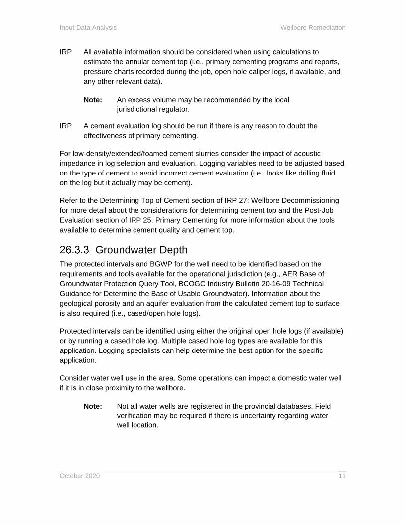
IRP All available information should be considered when using calculations to
estimate the annular cement top (i.e., primary cementing programs and reports,
pressure charts recorded during the job, open hole caliper logs, if available, and
any other relevant data).
Note: An excess volume may be recommended by the local
jurisdictional regulator.
IRP A cement evaluation log should be run if there is any reason to doubt the
effectiveness of primary cementing.
For low-density/extended/foamed cement slurries consider the impact of acoustic
impedance in log selection and evaluation. Logging variables need to be adjusted based
on the type of cement to avoid incorrect cement evaluation (i.e., looks like drilling fluid
on the log but it actually may be cement).
Refer to the Determining Top of Cement section of IRP 27: Wellbore Decommissioning
for more detail about the considerations for determining cement top and the Post-Job
Evaluation section of IRP 25: Primary Cementing for more information about the tools
available to determine cement quality and cement top.
Groundwater Depth
The protected intervals and BGWP for the well need to be identified based on the
requirements and tools available for the operational jurisdiction (e.g., AER Base of
Groundwater Protection Query Tool, BCOGC Industry Bulletin 20-16-09 Technical
Guidance for Determine the Base of Usable Groundwater). Information about the
geological porosity and an aquifer evaluation from the calculated cement top to surface
is also required (i.e., cased/open hole logs).
Protected intervals can be identified using either the original open hole logs (if available)
or by running a cased hole log. Multiple cased hole log types are available for this
application. Logging specialists can help determine the best option for the specific
application.
Consider water well use in the area. Some operations can impact a domestic water well
if it is in close proximity to the wellbore.
Note: Not all water wells are registered in the provincial databases. Field
verification may be required if there is uncertainty regarding water
well location.

Wellbore Remediation Input Data Analysis
October 2020 12
Porous Zone Isolation
IRP All open porosities should have a geological evaluation, including above and
below BGWP.
Once the porous intervals are identified determine which intervals are not hydraulically
isolated and proceed with job design. AER Directive 020: Well Abandonment provides
guidance on what types of formations require separate isolation in Alberta. Consult local
jurisdictional regulations for current requirements.
Evaluate casing and cement integrity between completion intervals selected for
isolation.
Water or Gas Shutoff and Injector Conformance
This remedial work is typically conducted to optimize production or injection.
The following information is useful for planning the remediation operation:
• Production/injection history of the well. Review offsetting wells to determine if reservoir characteristics are unique to this well or are similar to nearby wells.
• Additional logs to obtain fluid contact information (gas/oil, oil/water or gas/water contact) may be required for water and gas shutoff remediation work, channeling behind pipe and gas/water coning.
• Logs that define the flow of injection fluids behind casing (e.g., temperature, tracer, cement evaluation, oxygen activation and/or acoustic) are usually required prior to injector conformance work and may also be useful for water and gas shutoffs.
• Estimated rate of water contact rise or gas contact drop. This will help determine the appropriate standoff.
• Existing perforation depths and pay thickness, to determine if additional perforations can be placed in the reservoir.
Completion Interval Isolation
Confirm geology around the interval to be isolated. Plug setting depths are often
determined by caprock depths or similar geological considerations.
If the intervals in question are in stratigraphic communication at offset wells it may not
be necessary to isolate the two intervals at the subject well if approved by the local
jurisdictional regulator.
Confirm the casing condition as required. Mechanical plugs are most commonly used for
interval isolation but casing condition may not allow plug setting at the desired depth.

Input Data Analysis Wellbore Remediation
October 2020
13
This may require use of alternate plugs or interval isolation with cement/alternate
products.
Evaluate cement integrity between intervals selected for isolation. Additional work may
be required outside casing if cement integrity is suspect.
If a selected interval is designed for permanent zonal isolation refer to local jurisdictional
regulations and IRP 27: Wellbore Decommissioning for additional information about
requirements.
Casing Repair
The following information is useful for planning a remedial cementing operation:
• The casing interval that is affected (top and bottom depths).
• Accessibility to a desired depth for planned operations.
• Feed rate (volume and pressure) into the failure interval.
• Downhole conditions in certain areas (e.g., corrosion) that may accelerate the loss of casing integrity.
• Historical repair operations in the subject well and any offset wells.
• Casing inspection log (if appropriate).
• Future operations planned for the well (pressures, temperatures, fluid compositions, internal clearance needs, etc.)
• Expected breakdown pressure of zone outside casing failure
• Temperature at the intervention depth.
• Cementing information over the interval to be repaired
The following information may be necessary to determine the type of mechanical casing
repair to be completed and wellbore access technique(s) required:
• Sizes, weights, materials, pressure ratings and temperature ratings of the tubing and casing. Consider tapered and reverse-tapered string designs.
• Casing burst and collapse pressures (considering potential pressure hits from adjacent wells).
• Risk for formation shifting or communication from offset wells in the area.
• SCVF/GM source (see IRP 27: Wellbore Decommissioning section on SCVF/GM Source Identification for more information).
• Current well conditions and patching/repair history.

Wellbore Remediation Input Data Analysis
October 2020 14
• Future plans for the well (i.e., forecast pressures and temperatures, fluid types, expected life).

Technique Selection for Remedial Cementing Wellbore Remediation
October 2020
15
26.4 Technique Selection for Remedial Cementing
Access
This section describes the different access techniques used during wellbore remediation
operations for situations that require cement placement outside casing. Table 3 shows
common access techniques for each job type. Select the technique based on the best
information available at the time of job design.
Table 3. Access Techniques by Job Type
BGWP SCVF/ GM
Porous Zone
Isolation
Water Shutoff
Completion Zone
Isolation
Casing Repair
Perforations X X X X
Abrasive Jetting X
Mechanical Perforation
X X X X
Existing Access Point
X X X
Section Milling X X
A continuous 360 degree cut at one depth may result in misaligned casing.
26.4.1.1 Perforations
Conventional perforating parameters to consider include the following
• Open hole size vs. penetration depth
• Perforation shape (round vs. slot)
• Shot density
• Shot orientation
• Conveyance method
• Number of casing strings
• Formation type and materials behind casing

Wellbore Remediation Technique Selection for Remedial Cementing
October 2020 16
It is important to ensure there is enough access for annular cleanout.
26.4.1.2 Abrasive Jetting
The abrasive jet technique can be used to create 360° access to the annular space
behind the casing and access to the formation through a series of staggered cuts.
26.4.1.3 Mechanical Perforators
Mechanical perforation is a quick and effective method to gain access to the annular
space. It is also effective when multiple zones need to be accessed
26.4.1.4 Existing Access Point
Access points can include existing casing failures or existing perforations.
26.4.1.5 Section Milling
Section milling removes the entire interval of casing and cement and provides direct
access to the formation. This technique may limit or complicate future access to the
casing below the section that has been milled.
Regulatory approval may be required prior to section milling. Consult local jurisdictional
regulations.
IRP The operator shall ensure that lower zones have been decommissioned as
per local jurisdictional regulations prior to performing a section milling
operation.
Wellbore Preparation
During primary cementing, annular conditioning may be aided by deployment of
scratchers and/or centralizers and by pipe movement. These processes are not
available during remedial cementing operations (other than cementing in slim hole
casing) so chemical or hydraulic means of annular conditioning are often required.
Identify whether there is hydrocarbon buildup inside casing or tubulars prior to
cementing. Apply appropriate technology (e.g., spacer, surfactants, hot oiler, etc.) to
remove the buildup and then apply a water wetting agent.
The objective of wellbore preparation is to ensure communication exists between the
wellbore and the target for the cement and that materials used to establish
communication will not contaminate the cement.
IRP Conditioning fluids that will contact protected or usable groundwater
intervals must comply with local jurisdictional regulations.
Verify how the fluids being used in the treatment will interact with the formation and
formation fluid before commencing any treatment to prevent incompatibilities.

Technique Selection for Remedial Cementing Wellbore Remediation
October 2020
17
26.4.2.1 With Circulation
When circulation behind casing is desired, the following need to be considered about
the properties of the fluids used to establish and maintain circulation:
• The ability to remove filter cake from the borehole wall and remove solids/cuttings without plugging pathways.
• The ability to establish water-wet conditions on the surfaces of the casing and the formation.
• The ability to create/preserve borehole stability until the cement has been placed.
• The ability to remove cement-contaminating materials from the borehole-casing annular space prior to pumping cement into the annulus.
IRP Conditioning agents, pump rates, volumes and contact times should be based on
the following:
• Well history.
• Encountered formations.
• Geological drilling review.
• Drilling fluid records (e.g., type and composition of the drilling fluid, gelling/ viscosifying agents, bridging agents, weighting agents, etc.).
• Caliper and cement bond/evaluation logs.
• Existence/description of borehole stability.
• Pre-flush and spacers used during primary cementing.
• Rock mineralogy adjacent to sections of inadequate bonding (i.e., understand the interaction of cement pre-flush and cement with mineralogy).
• Treatment Pressure.
Surging/swabbing can be used alone or in conjunction with acid or drilling fluid cleanout agents to loosen material that may be plugging perforation tunnels and/or the casing from the casing annulus.
See IRP 25: Primary Cementing for more information about clay stabilizing fluids, water wetting and surfactants.
26.4.2.2 Without Circulation
When a non-circulation type squeeze is planned consider a pump-in test to determine
the feed rate. If sufficient feed rate is not attained consider acidizing, surging/swabbing,
washing or other debris removal techniques.

Wellbore Remediation Technique Selection for Remedial Cementing
October 2020 18
Table 4 shows techniques that could be used to gain circulation or to increase the feed
rate.
Table 4. Techniques to Gain Circulation or Increase Feed Rate
BGWP SCVF/ GM
Porous Zone
Isolation
Water Shutoff
Completion Zone
Isolation
Casing Repair
Stimulation Fluids X X X X X X
Surge and Swab X X X
Washing X X X X X
26.4.2.2.1 Stimulation Fluids
Pumping acid can help establish circulation/feed rates or lower treatment pressures.
Spotting solvents can help establish a feed rate or lower treatment pressures by
removing debris, scale, paraffins, high viscosity oil and asphaltenes.
26.4.2.2.2 Surging/Swabbing
Surging or swabbing techniques can be used on their own or in conjunction with the use
of stimulation fluids. This involves cycling a well through pressure and swab cycles to
loosen any blockages that may be present in the annulus and help establish circulation.
IRP Integrity of the casing, current operating limits and formation fracture pressure
should be considered when cycling the wellbore.
26.4.2.2.3 Washing
Washing techniques can help increase circulation or feed rates by clearing partial
blockages in the annulus.
Application and Conveyance
Table 5 shows techniques that could be used to complete a remedial cementing
squeeze operation. See Appendix B: Glossary for more information about squeezes.
Technique Selection for Remedial Cementing Wellbore Remediation
October 2020
19
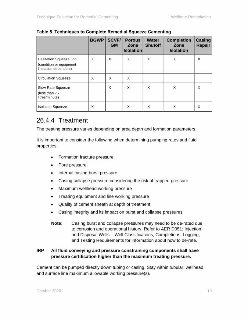
Table 5. Techniques to Complete Remedial Squeeze Cementing
BGWP SCVF/ GM
Porous Zone
Isolation
Water Shutoff
Completion Zone
Isolation
Casing Repair
Hesitation Squeeze Job
(condition or equipment limitation dependent)
X X X X X X
Circulation Squeeze X X X
Slow Rate Squeeze
(less than 75 litres/minute)
X X X X X
Isolation Squeeze X X X X X
Treatment
The treating pressure varies depending on area depth and formation parameters.
It is important to consider the following when determining pumping rates and fluid
properties:
• Formation fracture pressure
• Pore pressure
• Internal casing burst pressure
• Casing collapse pressure considering the risk of trapped pressure
• Maximum wellhead working pressure
• Treating equipment and line working pressure
• Quality of cement sheath at depth of treatment
• Casing integrity and its impact on burst and collapse pressures
Note: Casing burst and collapse pressures may need to be de-rated due
to corrosion and operational history. Refer to AER D051: Injection
and Disposal Wells – Well Classifications, Completions, Logging,
and Testing Requirements for information about how to de-rate.
IRP All fluid conveying and pressure constraining components shall have
pressure certification higher than the maximum treating pressure.
Cement can be pumped directly down tubing or casing. Stay within tubular, wellhead
and surface line maximum allowable working pressure(s).
Wellbore Remediation Technique Selection for Remedial Cementing
October 2020 20
Placement
Cement for wellbore remediation is most commonly placed in a well by circulating it in
through a tubing string or pumping directly down casing (a squeeze). Refer to Appendix
B: Glossary for more information about squeezes.
When performing a squeeze there is always a risk of cementing tubing in place. This
could occur due to, but not limited to, the following:
• Retainer failure
• Flow into casing above the retainer
• Tubing failure
• Operational error
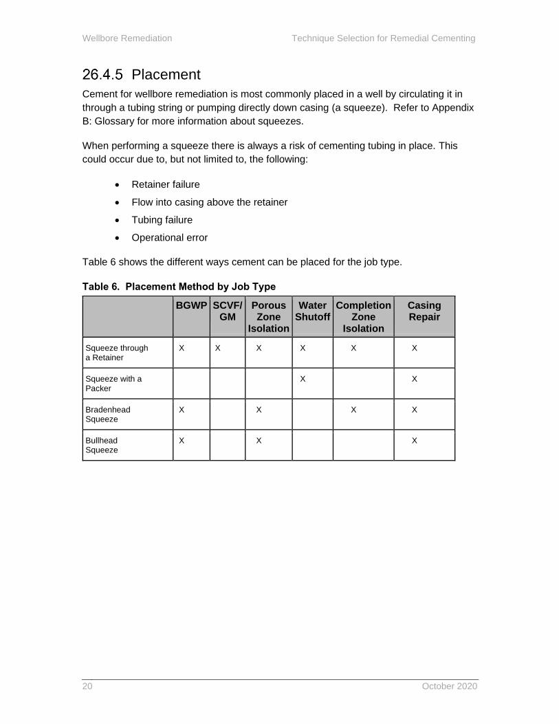
Table 6 shows the different ways cement can be placed for the job type.
Table 6. Placement Method by Job Type
BGWP SCVF/ GM
Porous Zone
Isolation
Water Shutoff
Completion Zone
Isolation
Casing Repair
Squeeze through a Retainer
X X X X X X
Squeeze with a Packer
X X
Bradenhead Squeeze
X X X X
Bullhead Squeeze
X X X
Technique Selection for Remedial Cementing Wellbore Remediation
October 2020
21
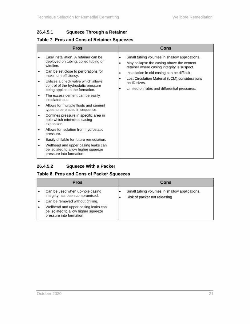
26.4.5.1 Squeeze Through a Retainer
Table 7. Pros and Cons of Retainer Squeezes
Pros Cons
• Easy installation. A retainer can be deployed on tubing, coiled tubing or wireline.
• Can be set close to perforations for maximum efficiency.
• Utilizes a check valve which allows control of the hydrostatic pressure being applied to the formation.
• The excess cement can be easily circulated out.
• Allows for multiple fluids and cement types to be placed in sequence.
• Confines pressure in specific area in hole which minimizes casing expansion.
• Allows for isolation from hydrostatic pressure.
• Easily drillable for future remediation.
• Wellhead and upper casing leaks can be isolated to allow higher squeeze pressure into formation.
• Small tubing volumes in shallow applications.
• May collapse the casing above the cement retainer where casing integrity is suspect.
• Installation in old casing can be difficult.
• Lost Circulation Material (LCM) considerations on ID sizes.
• Limited on rates and differential pressures.
26.4.5.2 Squeeze With a Packer
Table 8. Pros and Cons of Packer Squeezes
Pros Cons
• Can be used when up-hole casing integrity has been compromised.
• Can be removed without drilling.
• Wellhead and upper casing leaks can be isolated to allow higher squeeze pressure into formation.
• Small tubing volumes in shallow applications.
• Risk of packer not releasing

Wellbore Remediation Technique Selection for Remedial Cementing
October 2020 22
26.4.5.3 Bradenhead Squeeze
Table 9. Pros and Cons of Bradenhead Squeezes
Pros Cons
• Can be used over multiple intervals.
• No downhole mechanical barrier required.
• Can be used where there are up-hole wellbore diameter restrictions.
• Casing expansion may limit access to leak paths while attempting to inject cement.
• Difficult to control cement placement, particularly in low pressure formations.
• Pumping pressures limited by casing specifications
• Requires minimum volume of cement to be successful (depth and deviation dependent).
• Higher risk of channeling due to small tubing volumes in large casings
26.4.5.4 Bullhead Squeeze
Table 10. Pros and Cons of Bullhead Squeezes
Pros Cons
• Can be conducted with or without work string.
• Performed without service or coiled tubing rig.
• Casing expansion may limit access to leak paths while attempting to inject cement.
• Difficult to control cement placement.
• Limited pumping pressures.
• Requires cement plug curing period and plug top verification and pressure test.
• Prone to cement contamination in the casing.
• Easy to over-displace and contaminate cement in the wellbore.
Technique Selection for Mechanical Casing Repair Wellbore Remediation
October 2020
23
26.5 Technique Selection for Mechanical Casing Repair
The following techniques are available for mechanical casing repair:
• Internal patches
• Installation of a structural support liner
• Casing replacement
• External patches
The technique is chosen based on the following:
• The nature of the problem (i.e., deformation, restriction, reduced wall thickness, collapse or breach).
• Location and size of the problem.
• Casing integrity above the problem (e.g., wellbore restrictions above a breach).
• Size, weight, material, pressure rating and temperature rating of tubing and casing to be repaired.
• Casing burst and collapse pressures required (considering potential pressure hits from adjacent wells).
• Corrosion (internal or external).
• Deployment methods available and accessibility.
• Compatibility with offsetting Enhanced Oil Recovery (EOR) schemes (if in use)
Wellbore Access
The purpose of a wellbore access technique is to regain ID in the casing when there is a
restriction or deformation that prevents the passage of equipment when casing has not
been breached. Swedging or milling techniques can be used.
Wellbore Remediation Technique Selection for Mechanical Casing Repair
October 2020 24
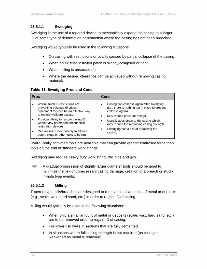
26.5.1.1 Swedging
Swedging is the use of a tapered device to mechanically expand the casing to a larger
ID at some type of deformation or restriction where the casing has not been breached.
Swedging would typically be used in the following situations:
• On casing with restrictions or ovality caused by partial collapse of the casing.
• When an existing installed patch is slightly collapsed or tight.
• When milling is unsuccessful.
• Where the desired clearance can be achieved without removing casing material.
Table 11. Swedging Pros and Cons
Pros Cons
• Where small ID restrictions are preventing passage of critical equipment this can be an effective way to restore wellbore access.
• Provides ability to restore casing ID without any permanent mechanical restoration devices.
• Can restore ID temporarily to allow a patch, plugs or other tools to be run.
• Casing can collapse again after swedging (i.e., there is nothing put in place to prevent collapse again).
• May reduce pressure ratings.
• Usually adds strain to the casing which may reduce the remaining casing strength.
• Swedging has a risk of breaching the casing.
Hydraulically activated tools are available that can provide greater controlled force than
tools on the end of standard work strings.
Swedging may require heavy duty work string, drill pipe and jars.
IRP A gradual progression of slightly larger diameter tools should be used to
minimize the risk of unnecessary casing damage, creation of a breach or stuck-
in-hole type events.
26.5.1.2 Milling
Tapered type mills/broaches are designed to remove small amounts of metal or deposits
(e.g., scale, wax, hard sand, etc.) in order to regain ID of casing.
Milling would typically be used in the following situations:
• When only a small amount of metal or deposits (scale, wax, hard sand, etc.) are to be removed order to regain ID of casing.
• For lower risk wells in sections that are fully cemented.
• In situations where full casing strength is not required (as casing is weakened as metal is removed).
Technique Selection for Mechanical Casing Repair Wellbore Remediation
October 2020
25
• On casing with small restrictions or ovality caused by minimal collapse of the casing.
• Over minor damage or over-torqued collars.
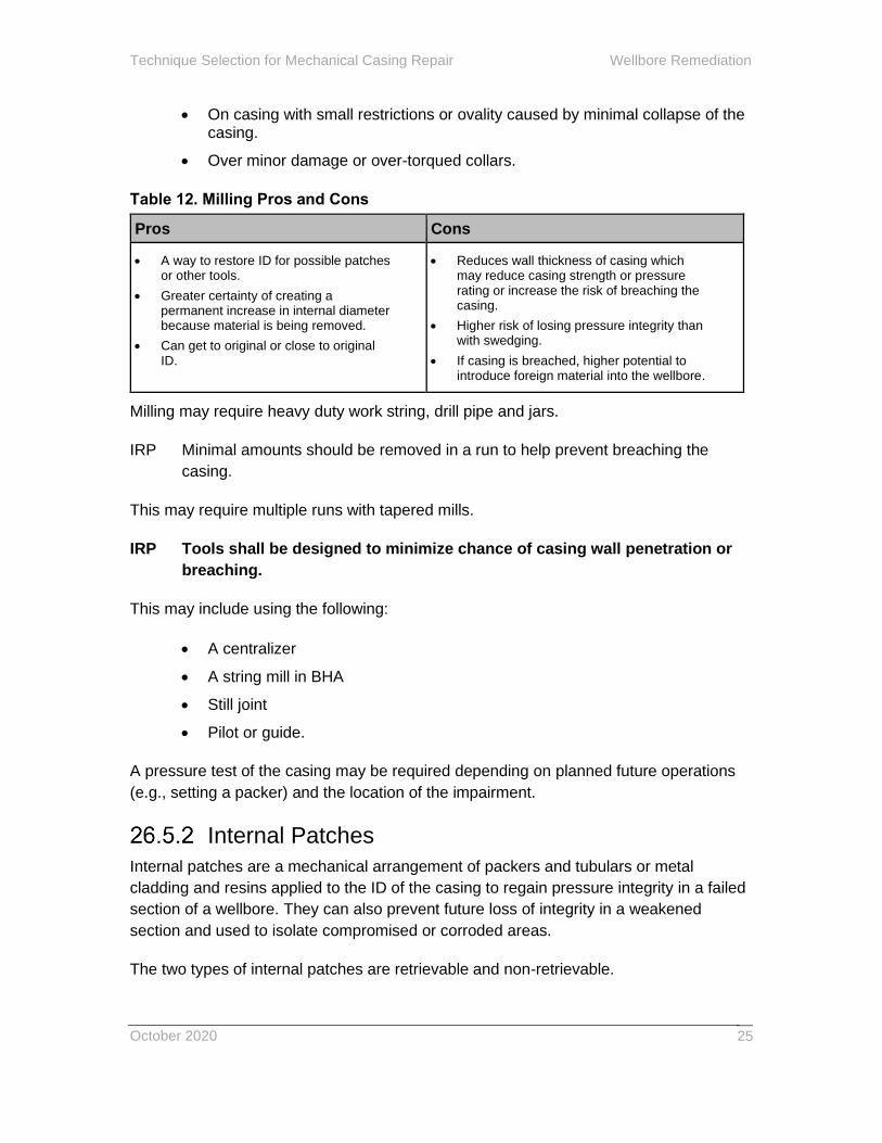
Table 12. Milling Pros and Cons
Pros Cons
• A way to restore ID for possible patches or other tools.
• Greater certainty of creating a permanent increase in internal diameter because material is being removed.
• Can get to original or close to original ID.
• Reduces wall thickness of casing which may reduce casing strength or pressure rating or increase the risk of breaching the casing.
• Higher risk of losing pressure integrity than with swedging.
• If casing is breached, higher potential to introduce foreign material into the wellbore.
Milling may require heavy duty work string, drill pipe and jars.
IRP Minimal amounts should be removed in a run to help prevent breaching the
casing.
This may require multiple runs with tapered mills.
IRP Tools shall be designed to minimize chance of casing wall penetration or
breaching.
This may include using the following:
• A centralizer
• A string mill in BHA
• Still joint
• Pilot or guide.
A pressure test of the casing may be required depending on planned future operations
(e.g., setting a packer) and the location of the impairment.
Internal Patches
Internal patches are a mechanical arrangement of packers and tubulars or metal
cladding and resins applied to the ID of the casing to regain pressure integrity in a failed
section of a wellbore. They can also prevent future loss of integrity in a weakened
section and used to isolate compromised or corroded areas.
The two types of internal patches are retrievable and non-retrievable.
Wellbore Remediation Technique Selection for Mechanical Casing Repair
October 2020 26
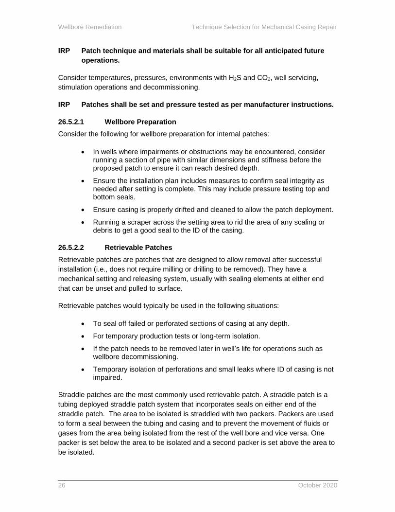
IRP Patch technique and materials shall be suitable for all anticipated future
operations.
Consider temperatures, pressures, environments with H2S and CO2, well servicing,
stimulation operations and decommissioning.
IRP Patches shall be set and pressure tested as per manufacturer instructions.
26.5.2.1 Wellbore Preparation
Consider the following for wellbore preparation for internal patches:
• In wells where impairments or obstructions may be encountered, consider running a section of pipe with similar dimensions and stiffness before the proposed patch to ensure it can reach desired depth.
• Ensure the installation plan includes measures to confirm seal integrity as needed after setting is complete. This may include pressure testing top and bottom seals.
• Ensure casing is properly drifted and cleaned to allow the patch deployment.
• Running a scraper across the setting area to rid the area of any scaling or debris to get a good seal to the ID of the casing.
26.5.2.2 Retrievable Patches
Retrievable patches are patches that are designed to allow removal after successful
installation (i.e., does not require milling or drilling to be removed). They have a
mechanical setting and releasing system, usually with sealing elements at either end
that can be unset and pulled to surface.
Retrievable patches would typically be used in the following situations:
• To seal off failed or perforated sections of casing at any depth.
• For temporary production tests or long-term isolation.
• If the patch needs to be removed later in well’s life for operations such as wellbore decommissioning.
• Temporary isolation of perforations and small leaks where ID of casing is not impaired.
Straddle patches are the most commonly used retrievable patch. A straddle patch is a
tubing deployed straddle patch system that incorporates seals on either end of the
straddle patch. The area to be isolated is straddled with two packers. Packers are used
to form a seal between the tubing and casing and to prevent the movement of fluids or
gases from the area being isolated from the rest of the well bore and vice versa. One
packer is set below the area to be isolated and a second packer is set above the area to
be isolated.
Technique Selection for Mechanical Casing Repair Wellbore Remediation
October 2020
27
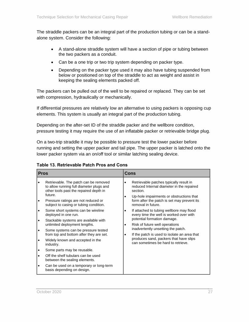
The straddle packers can be an integral part of the production tubing or can be a stand-
alone system. Consider the following:
• A stand-alone straddle system will have a section of pipe or tubing between the two packers as a conduit.
• Can be a one trip or two trip system depending on packer type.
• Depending on the packer type used it may also have tubing suspended from below or positioned on top of the straddle to act as weight and assist in keeping the sealing elements packed off.
The packers can be pulled out of the well to be repaired or replaced. They can be set
with compression, hydraulically or mechanically.
If differential pressures are relatively low an alternative to using packers is opposing cup
elements. This system is usually an integral part of the production tubing.
Depending on the after-set ID of the straddle packer and the wellbore condition,
pressure testing it may require the use of an inflatable packer or retrievable bridge plug.
On a two-trip straddle it may be possible to pressure test the lower packer before
running and setting the upper packer and tail pipe. The upper packer is latched onto the
lower packer system via an on/off tool or similar latching sealing device.
Table 13. Retrievable Patch Pros and Cons
Pros Cons
• Retrievable. The patch can be removed to allow running full diameter plugs and other tools past the repaired depth in future.
• Pressure ratings are not reduced or subject to casing or tubing condition.
• Some short systems can be wireline deployed in one run.
• Stackable systems are available with unlimited deployment lengths.
• Some systems can be pressure tested from top and bottom after they are set.
• Widely known and accepted in the industry.
• Some parts may be reusable.
• Off the shelf tubulars can be used between the sealing elements.
• Can be used on a temporary or long-term basis depending on design.
• Retrievable patches typically result in reduced Internal diameter in the repaired section.
• Up-hole impairments or obstructions that form after the patch is set may prevent its removal in future.
• If attached to tubing wellbore may flood every time the well is worked over with potential formation damage.
• Risk of future well operations inadvertently unsetting the patch.
• If the patch is used to isolate an area that produces sand, packers that have slips can sometimes be hard to retrieve.

Wellbore Remediation Technique Selection for Mechanical Casing Repair
October 2020 28
Pros Cons
• For straddle patches, the straddle tubing can be part of the production tubing and deployed and retrieved with it.
Consider the following when planning to use retrievable patches:
• Analysis of tubing expansion and contraction may be required.
• On thermal wells consider the stresses created on the packers and straddle tubulars created by temperature cycles.
Note: The lower side is usually not fixed in thermal patches.
• Requires sufficient wellbore clearance to allow the sealing elements to be run to depth.
• If wireline, coiled tubing or tubing has to be run through the straddle consider entry guides on either end of system to prevent post-job complications (e.g., getting stuck in the hole during remediation).
IRP A casing inspection log should be run prior to running the patch to determine the
extent of the issue and how much casing remains.
The data from the log can be used to determine the length of patch required and the
area to position the sealing elements.
IRP The areas below and above the area to be isolated should be pressure tested for
integrity before patch installation.
IRP A scraper should be run across the areas the packer elements will be set in to
prepare casing for the patch.
IRP A simulation tool of the same OD or larger than the retrievable system should be
run prior to installing the patch to ensure the patch/packer can be put in place.
IRP The installation plan should include measures to confirm seal integrity after
setting is complete.
This may include pressure testing top and bottom seals.
26.5.2.3 Non-Retrievable Patches
A non-retrievable patch is a patch that is designed to remain permanently in the well
after it has been successfully installed. These are patches that are typically single
run/use patch systems that require milling of sealing elements or complete patch in
order to be removed. Expandable patches and some patches with sealing elements that
are not designed for removal fall into this category.

Technique Selection for Mechanical Casing Repair Wellbore Remediation
October 2020
29
Non-retrievable patches are intended to provide sufficient pressure ratings for future
operations and are usually deployed with a rig.
Non-retrievable patches would typically be used in the following situations:
• To seal off failed or perforated sections of casing at any depth.
• For permanent isolation during production life of wellbore.
• Primary or secondary seal over perforations.
• For fracturing applications.
• To isolate splits, parts or leaking stage tools, fracture sleeves and open hole packers.
• For remediation and repair of internal corrosion.
• To cover casing impairments or failures.
Table 14. Non-Retrievable Patch Pros and Cons
Pros Cons
• These types of patches can provide larger internal diameter than can be achieved with retrievable patches.
• Some versions are better suited to seal on sections of casing that are not perfectly round.
• Downhole packers, anchors and retrievable and permanent bridge plugs can pass through some systems.
• Some systems can be deployed on live wells through a pressure control system (lubricator).
• Some systems can be wireline deployed.
• There are stackable systems available for straddling longer intervals.
• Removal is usually difficult (or impossible) and costly.
• Thinner wall thicknesses to achieve larger ID can result in lower collapse strength.
• Has higher expansion ratio. Can be extremely difficult to remove.
• May change erosion prediction planning for stimulation activities, through and below patch as a result of fluid dynamics.
Consider the following about thin metal clad systems:
• They may have limited internal and low external pressure ratings.
• Pressure ratings can vary depending on the hole size.
• Pressure rating is subject to tubing or casing condition.
Consider the following about heavier wall metal clad systems:
• Some systems just expand and seal on each end and are easier to remove.

Wellbore Remediation Technique Selection for Mechanical Casing Repair
October 2020 30
• They have higher pressure ratings from both sides.
• On some systems the pressure ratings are not reduced due to the casing conditions.
• They have a moderate expansion ratio.
• Some systems can be used to patch split and parted casing and can be deployed on E-Line, E-coiled tubing or regular coiled tubing so a patch can be deployed with rigless intervention.
• They can hold large amounts of weight without damage or moving.
• They are available in premium alloys and systems are available for extremely high well bore temperatures and conditions.
Structural Support Liner
Structural support liners are used to help prevent deformation or shifting of wellbores.
Permanent installations are mostly used in thermal operations, while temporary
installations can be used to help prevent shifting of failed sections and maintain access
to deeper sections of the wellbore in any type of well. Temporary liners are typically
designed with more clearance than permanent liners. Multi-joint structural support liners
usually have flush connections below the liner hanger
The purpose of a structural support liner is to provide a combination of material strength
and wall thickness to provide the structural reinforcement needed without reducing
internal diameter any more than necessary. The ID required is based on the type(s) of
jobs required after the liner is in place (e.g., pump and tubing size that needs to be run
past the liner).
Consider the following:
• Liners are not suitable for providing pressure integrity over a failed section because they have no seal on the bottom.
• Liner bottom can expand and contract so the liner remains in the elastic stress regime through thermal cycling.
• Liners reduce internal diameter which can limit operations below.
• Liners are removable but extraction can be difficult where further deformation or shifting has occurred or other material has fallen in behind the liner.
• Liners are not regulated, but regulatory requirements (like proper decommissioning as outlined in AER D020: Well Abandonment) need to be met after installation.
IRP The fit of the structural support liner should be as tight as possible through the
deformation in order to prevent further movement. Ideally, it would be in contact
with casing through the target section that is being supported.

Technique Selection for Mechanical Casing Repair Wellbore Remediation
October 2020
31
IRP The bottom of the liner should be flush without upset connection, to allow the
end of the liner to pass the deformation, and maximize potential for successful
retrieval in future.
Casing Replacement
Casing replacement is the replacement of weakened or failed casing with new casing to
restore integrity, wall thickness and pressure ratings.
There are two types of casing replacement:
Type 1 – new casing above an external patch
Type 2 – new casing only (via welding or back off/screw on new casing)
Casing replacement would typically be used to restore desired integrity in a casing string
that has failed or seen excessive wall loss. It is usually only possible near surface or on
casing strings that have not been cemented to surface
Casing replacement is not suitable for repairing areas of casing that have been
cemented in place unless they are close to surface and can be excavated. If this is
possible, casing can be repaired by backing off and replacing casing or by cutting and
welding on a coupling and new casing to surface if a coupling is not accessible from
excavation.
Table 15. Casing Replacement Pros and Cons
Pros Cons
• Generally provides maximum ID and longevity of available repair options. There is no restriction to the casing ID and the casing remains full bore.
• High internal and external pressure ratings can be achieved
• Damage caused by back-off, possible torque up issues when screwing casing back on
Consider the following:
• Casing needs to be able to be pulled.
• May require a rig and may require special jacking systems to remove the casing.
• Appropriate welding procedures and stress relieving required (if welding).
• Confined space work procedures may be needed if excavations are deep.
• Compromised casing can be removed by free point back off or with a mechanical, pyrotechnic or chemical type of cutter.

Wellbore Remediation Technique Selection for Mechanical Casing Repair
October 2020 32
IRP Wellbore should be isolated with a retrievable plug prior to repair.
IRP Casing integrity should be verified before attempting a casing back off to ensure
the casing has integrity to handle torque of back off procedure.
IRP After installation the replaced casing must be pressure tested as per local
jurisdictional regulations.
IRP The material grade and weight of casing above replacement depth should be
kept consistent with the rest of the casing string to keep a consistent internal
diameter and wellbore pressure rating.
IRP Casing material shall be suitable for all anticipated future operations.
Consider temperatures, pressures, environments with H2S and CO2, well servicing,
stimulation operations and decommissioning.
IRP Installation shall be as per manufacturer specifications with casing backoff
technique and tools required.
IRP Welding procedures must be as per local jurisdictional regulations and
appropriate for grade of casing.
IRP Casing shall be made up to the recommended torque of the connection
used.
External Patches
Eternal patches are applied to the outside of casing to permanently repair casing and
restore pressure integrity without reducing ID.
The style of external patch used is based on wellbore conditions and required operating
pressures.
External patches can be used on production (intermediate) casing, surface casing or
other string that can be accessed from surface.
One type of external patch uses an overshot to connect replacement casing to the
original casing where casing is cut and pulled. Casing is run above the patch. Consider
the following:
• Requires a rig and may require special jacking systems to remove the casing.
• Type of casing cutter to be used (i.e., internal mechanical cutter or e-line).
• Length of casing to be cut off based on condition of casing, corrosion, etc.

Technique Selection for Mechanical Casing Repair Wellbore Remediation
October 2020
33
• Stub may need to be dressed prior to running external patch.
For applications near-surface there are external material wraps that can be used to
reinforce damaged casing or repair a breach in the casing. External patches may be
metallic and sealed to the casing by welding or other seal techniques, or external
patches may be wrapped into place using composite materials based on fiberglass or
carbon fibre with epoxy or resin.
External patches would typically be used in the following scenarios:
• To repair casing above a low cement top, typically from external corrosion.
• When full-bore drift is required (i.e., lack of casing integrity above patch depth).
Table 16. External Patch Pros and Cons
Pros Cons
• There is no restriction to the casing ID and the casing remains full bore.
• External patches can be removed if not cemented in place.
• If replacing the casing, need to be able to successfully retrieve casing with the failed section, or milling will be required.
• Casing needs to be in suitable condition to get proper isolation with connection to the external patch.
Confirm exact length of corroded section before starting repair, usually with combination
of internal logs and external inspection if possible.
IRP Patches shall be set and pressure tested as per manufacturer instructions.
IRP After installation the patched casing must be pressure tested as per local
jurisdictional regulations.

Wellbore Remediation Technique Selection for Mechanical Casing Repair
October 2020 34
Materials Selection Wellbore Remediation
October 2020
35
26.6 Material(s) Selection
Once the technique has been selected the materials need to be chosen. The properties
and compatibility of the materials need to be considered. The material will either be
cement or some form of alternative product. Regardless of the material selected, all of
the objectives for the job need to be met.
Cement
Refer to IRP 25: Primary Cementing for information about cement properties and
compatibility.
In addition to the general recommendation for cement slurry design in IRP 25, the
following items need to be considered when designing the cement slurry:
• Lithology of remediation interval(s)
• Downhole tools (i.e., retainer valve size)
• Conveyance method
• Feed rate prior to cementing job
• Type of squeeze (i.e., Retainer, Bradenhead, Packer, Bullhead)
Well conditions will dictate the suitable cement particle sizes and required design
variables (e.g., fluid loss and transition time).
Spacer
Refer to IRP 25: Primary Cementing for information about spacer properties and
selection.
A spacer may be required for remedial operations if there are incompatibilities between
the cement and existing wellbore fluid or the cement and the displacing fluid.

Wellbore Remediation Materials Selection
October 2020 36
Alternatives to Cement
If an alternative to cement is to be used consider the following:
• Some alternatives to cement have properties that may impact the ability to conduct future well or intervention activities.
• Alternative products require approval or acceptance from the local jurisdictional regulator and may involve increased risk and/or safety precautions.
• Safety in the presence of groundwater. If there is potential for leaching or degradation into groundwater a risk assessment with mitigation may be conducted.
• Stability in the presence of expected well fluids, formation fluids and wellbore conditions. This could include new fluids introduced into or contacting the wellbore from offset well operations.
• Ability to withstand a differential pressure to maintain hydraulic isolation in the wellbore considering the operational requirements and the full life cycle of the well.
• Ability to maintain hydraulic isolation and well integrity considering future development or impacts on the reservoirs and the groundwater that the well has penetrated.
• Placement procedures to ensure the alternate product does not contact groundwater if not proven to be safe for use above BGWP.
• Product limitations and ability to prevent degradation as a result of future operations in the reservoir or wellbore, including novel production technologies.
• Product compatibility with current well materials, under current and future conditions.
• Procedures for handling, storage, transportation, installation, placement or disposal of the product.
IRP Any alternative to cement used in wellbore remediation must be approved
for use by the local jurisdictional regulator and all applicable
documentation, handling, compatibility and procedural guidelines of the
local jurisdictional regulator must be followed.
IRP The use of the alternate product shall be risk assessed and the appropriate
controls shall be in place to mitigate risks based on the Safety Data Sheet
or procedures for the product.
See the Alberta Upstream Petroleum Research report 18-WARI-04 – Chemical Cement
Alternatives for more information about qualifying an alternate product (see Appendix C:
References for link).
Job Execution Wellbore Remediation
October 2020
37
26.7 Job Execution
Input data analysis, technique selection and material selection drive the execution plan.
Field procedures, quality assurance and contingency plans need to be included.
IRP If an alternative to cement is to be used the procedures for installation and
verification defined by the product manufacturer shall be followed.
Field Procedures
One of the most critical phases during job execution is the calculation of the hole
volume required to be filled with cement. Downtime between establishing circulation or
feed rate, calculating the hole volume and completing the wellbore remediation needs to
be minimized in order to prevent loss of circulation or reduced pumping capabilities.
Depending on the objectives of the treatment and how the wellbore is responding, the
cement mixing method may be an important factor in the successful outcome of the
treatment.
Continuous mixing is the preferred option for the following requirements and
circumstances:
• Optimizing working time of the cement.
• Pumping multiple fluids.
• Cement volume to complete treatment is unknown.
• Large cement volume treatments.
Batch mixing is an option when the exact density and surface conditioning of cement
are known and volume required is within the capacity of the batch mix unit.
Quality Assurance
IRP Personnel responsible for the well treatment shall review the on-site well
configuration and conditions to confirm personnel and equipment align
with the treatment design.
IRP Any variances shall be discussed and evaluated with the well operator’s
representative(s) and corrective actions put in place.
Wellbore Remediation Job Execution
October 2020 38
Services need to be notified of changes so that their portion(s) of the treatment can be
adjusted prior to arriving on site.
See IRP 25: Primary Cementing for list of material and equipment checks to conduct as
part of the treatment and sample collection and handling.
IRP All samples collected on the job should indicate the following:
• Well operator name
• Unique Well Identifier
• Date and time of sample collection
• Sample source
• Sampling method
• List of contents
IRP A record of all data recorded, materials used and results achieved should be
retained with the well data.
A post-job review and documentation of variances and lessons learned can improve
future treatments in the area.
Contingency Plans
IRP All parties should review contingency plans prior to commencing treatment.
Events that may require contingency plans include the following:
• Loss of circulation
• Loss of circulation rate
• Cement fallback
• Equipment failure
• Weather conditions
• Loss of wellbore control
• Unexpected high pumping pressure
• Loss of containment on fluid returns
• Treatment commencement delay
• Casing failure
• Unexpected mix water condition (i.e., contamination, temperature)
See IRP 25: Primary Cementing for more information about contingency plans.

Post-Job Evaluation Wellbore Remediation
October 2020
39
26.8 Post-Job Evaluation
All jobs need to be evaluated against job objectives to verify success or identify further
remediation required.
IRP Wellbore pressure testing must be performed after a cement plug has been
drilled out to confirm wellbore integrity.
Consult a technical expert responsible for the cement product for appropriate wait times
prior to pressure testing and tagging the cement.
Note: Tagging the cement may be completed before or after pressure
testing.
IRP Cement top must be verified using a method approved by the local
jurisdictional regulator.
IRP Cement top depth must be as per local jurisdictional regulations.
Cement Sample Evaluation
If samples were collected during execution of the job they can be evaluated for product
performance.
Note: Cement slurry cup samples at surface do not represent downhole
conditions.
Groundwater Protection
If cement returns were observed during job execution, intervals between the perforated
interval and surface are considered to be isolated from one another assuming proper
cementing practices were followed and no fallback has been observed. A comparison
between expected annular volume and actual volume can be evaluated. If the
calculated annular volume is greater than the volume of the cement placed in the
annulus, a cement evaluation log may be necessary to confirm hydraulic isolation.
If no returns are seen at surface, a log will need to be run to determine cement top and
ensure multiple zone isolation. A cement evaluation log is most common and the
minimum length of time prior to logging can be estimated by the cementing service
supplier. Temperature logs can also be used within a short time interval of cementing.
Wellbore Remediation Post-Job Evaluation
October 2020 40
Confirm optimal log(s) to run with the cementing service provider as some may be time
sensitive.
If multiple groundwater intervals exist above cement top an additional cement job is
typically required to isolate those intervals from each other. If there are no groundwater
intervals or only one protected interval above cement top additional cementing may not
be required.
Porous Zone Isolation
26.8.3.1 Circulation
Refer to 26.8.2 Groundwater Protection for evaluation of cement circulation operations.
26.8.3.2 Multiple zone isolation
Pressure test and verify the cement top of each separate cement plug.
Water or Gas Shutoff and Injection Conformance
Production fluid composition, reduction in unwanted fluid(s) and increase in optimal
production fluid are leading indicators of a successful operation in water and gas shutoff
work. Post job production monitoring is the key to determining success or failure.
For post-job evaluation of injector conformance work, post-job production logs are
typically compared to pre-job logs to determine success.
Pressure test to confirm perforations are isolated before perforating at a new depth.
If unsuccessful, additional logging and alternate shutoff techniques may be considered
along with consultation with reservoir/production engineering and geoscience technical
experts.
Completion Interval Isolation
The most common measures of success are a pressure test to confirm the interval is
isolated and, in some cases, tagging the final level of cement after it is set to confirm
plug placement meets requirements. Top up may be required if requirements are not
met.
Depending on well conditions, cased hole logs can be run to confirm isolation of specific
intervals (e.g., injection wells).

Post-Job Evaluation Wellbore Remediation
October 2020
41
Casing Repair
26.8.6.1 Cement Squeeze
Record drilling characteristics and observations of returns as the cement plug is drilled
out. Record apparent depth of the bottom of the set cement plug.
26.8.6.2 Slim Hole Casing
Cementing in a slim hole casing string is similar to a primary cement job. Most criteria
for post job evaluation are similar to those noted in IRP 25: Primary Cementing. Monitor
and record returns to confirm cement fills the volume outside the slim hole casing. Also
monitor for cement fallback after the job.
Cement bond logs can be run to help confirm cement top and cement sheath integrity,
most commonly where there are issues identified with the cementing process.
Pressure test the cemented string to maximum expected operating pressure plus an
appropriate safety factor. Completing a pressure test after drilling out the bottom of the
slim hole casing and before drilling out the isolation plug can provide indication of
integrity at the slim hole casing shoe.
26.8.6.3 Mechanical Casing Repair
Post job evaluation for a mechanical casing repair typically includes the following:
• Confirmation that internal clearance through the repair is sufficient for future operations.
• Pressure testing the repair to confirm required pressure integrity for future operations has been regained.
Post-job pressure testing may or may not be required by the local jurisdictional regulator
depending on where the repair is located. Pressure testing top and bottom elements is
typically required by local jurisdictional regulations for out-of-zone repairs. In-zone
pressure testing is at the typically at discretion of the operator. Refer to AER ID 2003-01
for pressure testing requirements.

Wellbore Remediation Post-Job Evaluation
October 2020 42

Appendix A: Revision Log Wellbore Remediation
October 2020
43
Appendix A: Revision Log
The revisions to IRP 26 are logged in the following table. Refer to 26.0.11 Background
for additional information about the history of this IRP.
Table 17. Revisions Summary
Edition Section(s) Remarks/Changes
1 New IRP sanctioned October 2020
1 Casing Repair Updates
The sections noted here were updated during initial industry review of IRP 26 and released with the IRP 26 final review.
26.0.3 Scope and Limitations
Removed comments about the document not including mechanical casing repair content.
26.0.6 Acknowledgments
Added casing repair subcommittee members to table.
26.0.8 Background Updated information about including mechanical casing repair content.
26.2.7.3 Mechanical Casing Repair
Content added based on the remediation types included in the document.
26.3.8 Casing Repair
Data specific to mechanical casing repair added.
26.5 Technique Selection for Mechanical Casing Repair
Section 26.4 Technique Selection renamed to Technique Selection for Remedial Cementing and 26.5 added to address technique selection considerations for mechanical casing repair.
26.8.8.3 Mechanical Casing Repair
Added content for post-job testing for mechanical casing repair.

Wellbore Remediation Appendix A: Revision Log
October 2020 44

Appendix B: Glossary Wellbore Remediation
October 2020
45
Appendix B: Glossary
AER Alberta Energy Regulator
Alternate Products Any combination of the following alternatives to cement:
• Chemical and/or mechanical products that provide hydraulic isolation in the wellbore as a permanent barrier system and which can be a combination of chemical and mechanical components.
• Any wellbore sealing material other than a conventional cement blend as outlined in IRP 25: Primary Cementing. A cement-based product is considered an alternate product if it has advanced or unique properties or contains unconventional additives.
Base of Groundwater Protection (BGWP) As per AER: “The base of groundwater
protection (BGWP) is the best estimate of the elevation of the base of the formation in
which non-saline groundwater occurs at that location. However, local variations in
geology and topography are typical, so the actual elevation of the base of the
designated formation can often vary from what is provided in the BGWP tool.”
Base of Usable Groundwater (BUGW) As per BC Oil and Gas Commission (BCOGC)
and Section 18 of the Drilling and Production Regulation: the base of usable
groundwater is “the depth of all porous strata that are (a) less than 600 m below ground
level and (b) contain non-saline groundwater that is usable for domestic or agricultural
purposes”. Usable is defined by the BCOGC as groundwater with up to 4000 mg/L total
dissolved solids. In this IRP, usable is referred to as non-saline throughout.
BCOGC BC Oil and Gas Commission
DACC Drilling and Completions Committee
EOR Enhanced Oil Recovery
Gas Migration (GM) A flow of gas that is detectable at surface outside of the outermost
or surface casing string (often referred to as external migration or seepage).
Hydraulic Isolation No unplanned movement of fluids including all phases of liquid, gas
and vapor inside and/or outside the wellbore either between zones or to surface.
Prevention of unplanned fluid flow under specific or designed differential pressure.
Check with the local jurisdictional regulator for the applicable definition.
Wellbore Remediation Appendix B: Glossary
October 2020 46
ID Inside Diameter
LCM Loss Circulation Material
Permanent (or Eternal) One million days or 3000 years (as per the NORSOK D010).
Porous Interval/Zone IRP 27 uses the AER definition of a porous zone as found in
AER D020: Well Decommissioning.
A zone that
• has carbonates with effective porosity greater than one percent,
• has sandstones with effective porosity greater than three percent,
• Has offset production, regardless of the porosity or
• has drill stem test formation fluid recoveries greater than 300 linear metres or gas volumes greater than 300 cubic metres.
Note: The definition of ‘effective porosity’ varies by jurisdiction. Consult
local jurisdictional regulations for specifics.
Protected Interval IRP 27 uses the AER definition of a protected interval as found in
AER D020: Well Decommissioning. Any lithology above base of groundwater with
greater than three percent porosity or any coal seam.
Saline and Non-Saline Groundwater Definition as per the Alberta Water Act defines
saline groundwater as “water with total dissolved solids (TDS) content exceeding 4000
milligrams per litre (mg/L).” Although not explicitly defined, as stated in the AER’s
Bulletin 2007-10, the AER considers aquifers with TDS content less than 4000 mg/L as
non-saline and may be contained in sandstones, siltstones, coals, or fractured shales.
SME Subject Matter Expert
Squeeze Squeezing cement is the process of using pump pressure to inject or squeeze
cement into a problematic void space at a desired location in the well. Squeeze
cementing operations can be performed at any time during the life of the well: drilling,
completions or producing phases and can be completed above or below the fracture
gradient of the exposed formation. The squeeze cement (or alternate product) is
designed to match the specific type of void in the wellbore (e.g., a small crack or micro-
annulus, casing split or large void(s), formation rock or another kind of cavity).
• Bradenhead Squeeze: A Bradenhead squeeze is performed by circulating cement slurry down through the tubing to the squeeze interval, then pulling the work string above the top of the cement column. The backside of the wellbore is closed in and pressure is applied through the work string to force cement into the squeeze interval. A hesitation squeeze is sometimes used to
Appendix B: Glossary Wellbore Remediation
October 2020
47
more effectively pack off the cement into all voids. Most coiled tubing squeeze applications are performed using this technique.
• Bullhead Squeeze: A squeeze of all wellbore fluids into the formation(s) ahead of the cement slurry.
• Circulation Squeeze: A squeeze between two sets of perforations or between a perforated interval and surface by using a retainer set above the lower perforation interval.
• Hesitation Squeeze: During a hesitation squeeze the pumping sequence is started and stopped repeatedly while monitoring pressure on the surface Cement is deposited in waves into the squeeze interval. The slurry is designed to increase resistance (gel-strength development and fluid-leakoff rate) until the final squeeze pressure is reached. Follow hesitation thickening time laboratory testing procedures.
• Isolation Squeeze: Placement of a set volume of cement behind casing.
TDS Total Dissolved Solids
Surface Casing Vent Flow (SCVF) The flow of gas and/or liquid or any combination out
of the surface casing/production casing annulus (also referred to as sustained casing
pressure in jurisdictions where vents are closed).
Zonal Isolation Zonal isolation is the prevention of communication between discrete
porous zones (including between hydrocarbon bearing formations) and freshwater
aquifers.
Wellbore Decommissioning Well abandonment (as referenced in AER D020: Well
Abandonment). This IRP moves away from use of the term ‘abandonment’ to the more
descriptive term of wellbore decommissioning but many regulations still refer to this
activity as abandonment. See IRP 27: Wellbore Decommissioning for more information
about the transition to this wording.

Wellbore Remediation Appendix B: Glossary
October 2020 48
October 2020
49
Appendix C: References and Resources
DACC References
Available from www.EnergySafetyCanada.com
• IRP 25: Primary Cementing
• IRP 27: Wellbore Decommissioning (to be released for industry review in Q2 2020)
Local Jurisdictional Regulations and Information
Alberta
Available from the AER at www.aer.ca
• Base of Groundwater Protection Query Tool
• Directive 020: Well Abandonment
• Directive 079: Surface Development in Proximity to Abandoned Wells
• ID 2003-01: 1) Isolation Packer Testing, Reporting, and Repair Requirements; 2) Surface Casing Venting Flow/Gas Migration Testing, Reporting, and Repair Requirements; 3) Casing Failure Reporting and Repair Requirements
• Bulletin 2009-07: Revisions to the Digital Data Submission System Regarding Interim Directive 2003-01.
Available from the Government of Alberta
• Alberta Water Act, Revised Statutes of Alberta 2000. Chapter W-3, December 15, 2017.
Wellbore Remediation Appendix B: Glossary
October 2020 50
British Columbia
Available from the BC Oil and Gas Commission at www.bcogc.ca/legislation
British Columbia Oil and Gas Activity Operations Manual
• Chapter 9 - Well Completions, Maintenance and Abandonment
• Chapter 10 - Well Activity: Production and Injection Disposal
Drilling & Production Regulation – B.C. Reg 282/2010
• Part 4 – Well Operations, Division 3 – General Well Equipment
• Part 4 – Well Operations, Division 4 – Procedures
• Part 5 – Abandoning, Plugging and Restoring Wells.
INDB 2016-09 Technical Guidance for Determining the Base of Usable Groundwater
Oil and Gas Activities Act (OGAA) – (SBC 2008) Chapter 36
Water Sustainability Act – B.C. Reg. 39/2016
• Groundwater Protection
• Part 3 – Well Construction, Division 3 – Surface Seals
• Part 9 - Well Deactivating & Decommissioning
Note: By law, wells authorized under the Oil & Gas Activities Act are
NOT covered by the Water Sustainability Act. However, BCOGC
looks at the provisions of the Groundwater Protection Regulation
when assessing whether or not the Drilling & Production
Regulation requirements around hydraulic isolation are met.
Manitoba
Available from the Government of Manitoba at www.manitoba.ca
Drilling and Production Regulation
• Part 6 – Drilling, Completing, Servicing and Abandonment
The Oil and Gas Act - C.C.S.M. c. O34
• Part 9 – Oil and Gas Production and Conservation

October 2020
51
Saskatchewan
Available from the Government of Saskatchewan at www.saskatchewan.ca
Oil and Gas Conservation Act –Chapter O-2
Oil and Gas Directives and Guidelines available from
www.saskatchewan.ca/business/agriculture-natural-resources-and-industry/oil-and-
gas/oil-and-gas-legislation-regulations-and-ministers-orders
• Saskatchewan: PNG005: Casing and Cementing Requirements
• Saskatchewan: PNG010: Well Logging Requirements
• Saskatchewan: PNG015: Well Abandonment Requirements
• Saskatchewan: PNG026: Gas Migration
• Saskatchewan: PNG008: Disposal & Injection Well Requirements.
• Saskatchewan (Water Well) – SR172-66 The Groundwater Regulations
• Saskatchewan – The Water Security Agency Regulations
Oil and Gas Legislation and Regulations, 2012 – Chapter O-2 Reg 6
• Part 7 – Drilling, Completing and Servicing Wells
• Part 8 – Production Operations
Other References
• Alberta Upstream Petroleum Research report 18-WARI-04 – Chemical Cement Alternatives, September 2019. Available from https://auprf.ptac.org/well-abandonment/chemical-cement-alternatives/
• NORSOK D-010: Well integrity in drilling and well operations, Edition 4, 2013

Wellbore Remediation Appendix B: Glossary
October 2020 52