Embed Size (px)
Citation preview

IRONMAN INVERSION TABLE ITEM# 5501/5502
OWNER’S MANUAL
The specifications of this product may vary from this photo and are subject to change without notice. IRONMAN, IRONMAN TRIATHLON and M-DOT are registered trademarks of World Triathlon Corporation. This product is licensed by the IRONMAN TRIATHLON.

IMPORTANT: FOR NORTH AMERICA ONLY
To request product service and order replacement parts, please call our customer service department at: 1-866-924-1688 Monday through Friday, 8:00 AM-5:00 PM Pacific Standard Time,
or email us at: [email protected] visit our website at www.paradigmhw.com.
Please have the following information ready when requesting for service: Your name Phone number Model number Serial number Part number Proof of Purchase
*Before returning this product to the store please contact customer
service at the contact number.
Paradigm Health & Wellness, Inc. 1189 Jellick Ave. City of Industry, CA 91748, USA
1

TABLE OF CONTENTS
Warranty -------------------------------------------------------------------------------------------- 3
Warning Label Placement ---------------------------------------------------------------------- 4
Important Safety Precautions ------------------------------------------------------------------ 5
Included Hardware ------------------------------------------------------------------------------- 6
Tools ------------------------------------------------------------------------------------------------- 6
Overview Drawing -------------------------------------------------------------------------------- 7
Parts List -------------------------------------------------------------------------------------------- 8
Assembly Instructions --------------------------------------------------------------------------- 9
Operation and Adjustments -------------------------------------------------------------------- 14
Maintenance Instructions ----------------------------------------------------------------------- 17
Storage ---------------------------------------------------------------------------------------------- 18
Warm Up -------------------------------------------------------------------------------------------- 19
Parts Request Fax Form ----------------------------------------------------------------------- 21
2

ONE YEAR LIMITED WARRANTY Paradigm Health & Wellness, Inc. warrants to the original purchaser that this product is free from
defects in material and workmanship when used for the purpose intended, under the conditions that
it has been installed and operated in according to Paradigm’s Owner’s Manual. Paradigm’s
obligation under this warranty is limited to replacing free of charge, any parts which may prove to be
defective under normal home use. This warranty does not include any damage caused by improper
operation, misuse or commercial application. From the date of purchase, the product is warranted
to be free from defects for 1 (one) year. All parts and workmanship, including upholstery, foam, ball
bearings, pulleys, cables, shocks, all tension mechanisms, wheels, pedals and hardware are to be
free from defects for 90 days. This warranty is offered only to the original owner and is not
transferable. Proof of purchase is required. This warranty is offered only to the original owner and
is not transferable.
Ordering Replacement Parts Replacement parts can be ordered by calling or emailing our customer service department
[email protected] 1-866-924-1688 Monday through Friday, 8:00 AM - 5:00 PM (PST).
When ordering replacement parts please have the following information ready:
1. Owner’s Manual 2. Model Number 3. Description of Parts 4. Part Number 5. Date of Purchase
3
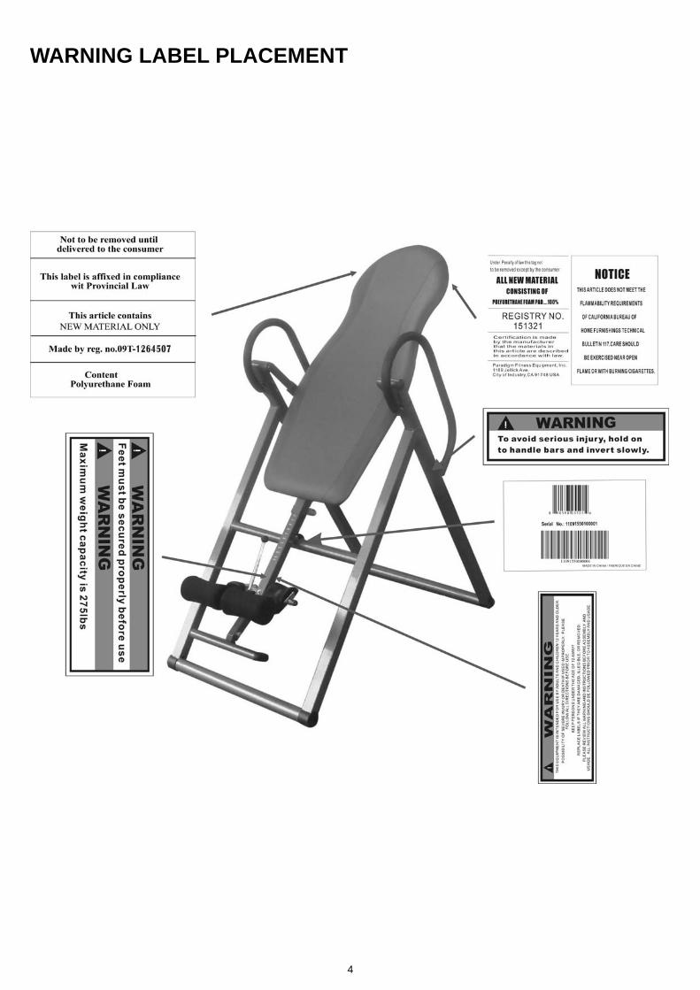
WARNING LABEL PLACEMENT
4

IMPORTANT SAFETY PRECAUTIONS Read all instructions carefully before assembling operating this product. Retain this owner’s manual and keep the original purchase receipt for future reference. 1. Consult your physician or other health care professionals before using the inversion table. 2. Always wear proper exercise apparel when using the equipment. 3. If any time you feel faint, light-headed or dizziness while operating the equipment, stop exercise immediately. You should also stop exercising if you are experiencing pain or pressure. 4. Keep children and pets away from the equipment while in use. 5. Only one person should use the equipment at a time. 6. Make sure your equipment is correctly assembled before you use it. Be sure all screws, nuts,
and bolts are tightened prior to use. 7. Do not operate this or any exercise equipment if it is damaged. 8. Watch your body: come up slowly, dizziness after a session means you came up too fast. Wait a while after eating before using the inversion table. If you get nauseous, come up as soon as you feel queasy.
9. Always use this equipment on a clear and level surface. Do not use outdoors or near water. 10. Keep hands and feet away from any moving parts. Do not insert any object into any openings. 11. Keep loose clothes, jewelry away from moving parts. 12. WARNING: ALWAYS HOLD ON TO THE HANDLEBARS AND GO BACK SLOWLY WHEN
INVERTING. FAILURE TO COMPLY COULD RESULT IN SERIOUS BODILY INJURY. 13. Children under the age of 12 should not use the following fitness equipment. 14. For indoors household use only. 15. For any problems please contact customer service at the contact number in this manual.
DO NOT ATTEMPT TO SERVICE THE UNIT YOURSELF. WARNING: Consult with your personal physician to see if inversion equipment is appropriate for you. This is especially important for people with pre-existing health problems. Do not use this equipment without your physician's approval. Do not use this equipment if you have any of the following conditions or ailments: .Extreme obesity .Glaucoma, retinal detachment or conjunctivitis .Pregnancy .Spinal injury, Cerebral Sclerosis, or acutely swollen joints .Middle ear infection .High blood pressure, Hypertension, Recent stroke or Transient Ischemic attack .Heart or circulatory disorders for which you are being treated .Hiatus hernia or Ventral hernia .Bone weaknesses including Osteoporosis, Unhealed fractures, Modularly pins, or Surgically
implanted orthopedic supports. .Use of anti-coagulants including Aspirin in high doses. Maximum Weight Capacity is 275 lbs/ 125 kgs.
5

INCLUDED HARDWARE
(19) Flat Washer Ø16xØ8.5x1.5
12 PCS
(20) Hexagon Socket Head
Cap Bolt M8x60mm 4 PCS
(21) Nylon Nut M8 (Black) 4 PCS
(26) Ring Pin Ø8x63.5mm 1 PC
(24) Nut Cap M8 4 PCS
(28) Hexagon Socket Head Cap Bolt M8x20mm
4 PCS
(43) Flat Washer Ø16xØ10.5x2.0
1 PC
(44) Metal Bushing 1 PC
(42) Nylon Nut M8
(Galvanization) 1 PC
(47) Flat Washer Ø18xØ10.5x2.0
1 PC
(46) Hexagon Head Bolt M10x42mm
1 PC
(45) Hexagon Head Bolt M8x48mm
1 PC
(48) Nylon Nut M10 1 PC
TOOLS
Wrench #13 & #17 2 PCS
Allen Wrench #6 1 PC
6

OVERVIEW DRAWING
37
23
35
37
36
22
14
14
7
9 8
2
3
5
10
4
6
11
1
12
13
40
41
2627
20
20
19
19
19
21
21
21
21
24
24
17
1828
28
29
31
32
32
32
33
3334
38
36
22
15
16
42
43
44
45
46
495051
25
30
30
19
19
39
39
4847
31
31
31
27
29
52
19
1828 1719
52
19
7
13
32
34
32
33
6
12
28
11
7

PARTS LIST
Part# Description Quan.Part# Description Quan.001 Backrest (#5501/#5502) 1 027 Hexagon Socket Head Cap Bolt
M8x65mm 2
002 Backrest Frame 1 028 Hexagon Socket Head Cap Bolt M8x20mm
6
003 Adjustable Boom 1 029 Plastic Washers 4 004 Foot Bar 1 030 Foot Bar Oval End Cap 2 005 Adjustable Instep Frame 1 031 Foot Cap 4 006 Handlebar 2 032 Flat Washer Ø13xØ6.5x1.5 6 007 Steel Heel Holder Bracket 2 033 Bolt M6x12mm 4 008 Rear Frame 1 034 Bolt M6x50mm 2 009 Front Frame 1 035 Loop Strap 1 010 Rod 1 036 Rubber Pad 2 011 Pivot Arm 2 037 Safety Hook 2 012 Handlebar Foam Grip 2 038 Square End Cap □33 1 013 Front Heel Holder 2 039 Adjustable Instep Frame Round
End Cap 2
014 Rubber Rear Heel Holder 2 040 Adjustable Instep Frame Knob 1 015 Spring Latch 1 041 Adjustable Boom Knob 1 016 Spring 1 042 Nylon Nut M8 (Galvanization) 1 017 Plastic Spacer 4 043 Flat Washer Ø16xØ10.5x2.0 1 018 Plastic Round End Cap 2 044 Metal Bushing 1 019 Flat Washer Ø16xØ8.5x1.5 14 045 Hexagon Head Bolt M8x48mm 1 020 Hexagon Socket Head Cap Bolt
M8x60mm 4 046 Hexagon Head Bolt M10x42mm 1
021 Nylon Nut M8 (Black) 6 047 Flat Washer Ø18xØ10.5x2.0 1 022 Rod Cap Ø22 2 048 Nylon Nut M10 1 023 Nylon Strap 1 049 Hexagon Head Bolt M6x40mm 1 024 Nut Cap M8 4 050 Flat Washer Ø18xØ6.5x1.5 1 025 Square End Cap □30 1 051 Nylon Nut M6 1 026 Ring Pin Ø8x63.5mm 1 052 Handlebar Round End Cap Ø25 2
#5501 #5502
8
ASSEMBLY INSTRUCTIONS
1 Ring Pin (Ø8x63.5mm)
Hardware:
8
9
26
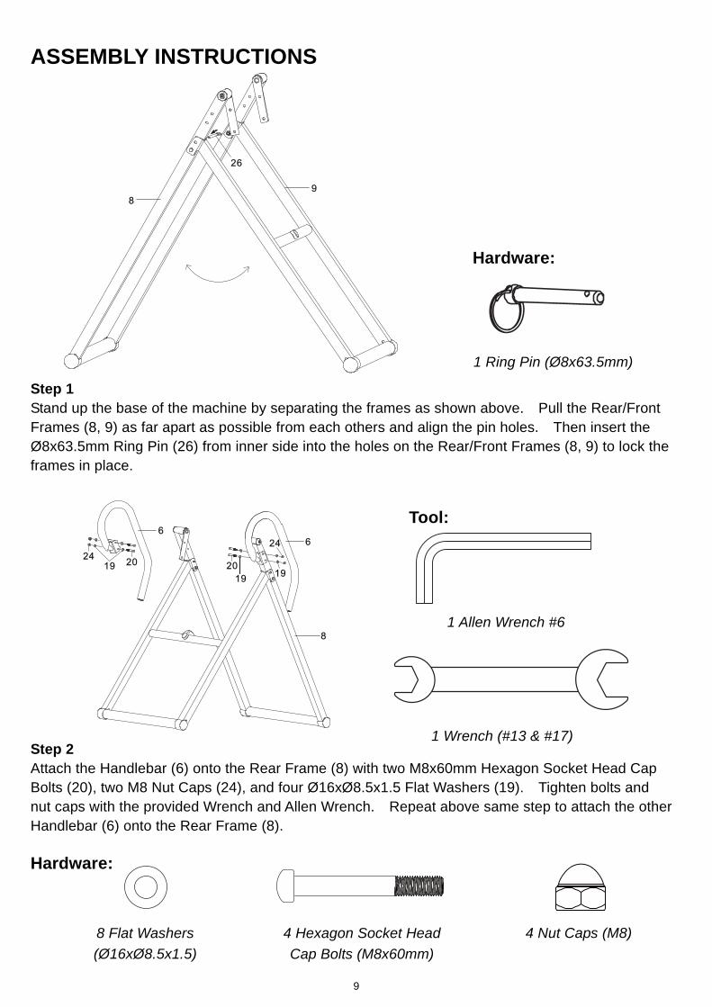
Step 1 Stand up the base of the machine by separating the frames as shown above. Pull the Rear/Front Frames (8, 9) as far apart as possible from each others and align the pin holes. Then insert the Ø8x63.5mm Ring Pin (26) from inner side into the holes on the Rear/Front Frames (8, 9) to lock the frames in place.
6
2020
19
24
24
19
19
8
6
Tool:
1 Allen Wrench #6
1 Wrench (#13 & #17)
Step 2 Attach the Handlebar (6) onto the Rear Frame (8) with two M8x60mm Hexagon Socket Head Cap Bolts (20), two M8 Nut Caps (24), and four Ø16xØ8.5x1.5 Flat Washers (19). Tighten bolts and nut caps with the provided Wrench and Allen Wrench. Repeat above same step to attach the other Handlebar (6) onto the Rear Frame (8). Hardware:
8 Flat Washers (Ø16xØ8.5x1.5)
4 Nut Caps (M8) 4 Hexagon Socket Head Cap Bolts (M8x60mm)
9

1
2
28
28
192119
11
11
Tool:
1 Allen Wrench #6
1 Wrench (#13 & #17)
Step 3 Mount the Backrest Frame (2) to the Pivot Arms (11) by inserting the ends of the Pivot Arms (11) into the brackets, located at each side of the Backrest Frame (2), align to the bolt holes on the Pivot Arms (11) and brackets. Using four M8x20mm Hexagon Socket Head Cap Bolts (28), four Ø16xØ8.5x1.5 Flat Washers (19), and four M8 Nylon Nuts (Black) (21) to attach the Backrest Frame (2) onto the Pivot Arms (11). Tighten bolts and nylon nuts with provided the Wrench and Allen Wrench. Hardware:
4 Flat Washers (Ø16xØ8.5x1.5)
4 Nylon Nuts (M8) (Black)
4 Hexagon Socket Head Cap Bolts (M8x20mm)
3
5
403
Step 4 Pull up on the Adjustable Instep Frame Knob (40), slide the Adjustable Instep Frame (5) completely out of the Adjustable Boom (3) and then turn the Adjustable Instep Frame (5) with the adjustable holes facing up. Release the Adjustable Instep Frame Knob (40) and adjust the Adjustable Instep Frame (5) slightly until the Adjustable Instep Frame Knob (40) locks into place.
10

3
4
46
4847
Tool:
2 Wrenches (#13 & #17)
Step 5 Slide the Foot Bar (4) into the bottom of the Adjustable Boom (3) and align the hole on the Foot Bar (4) with the hole on the Adjustable Boom (3). Secure the Foot Bar (4) in place using one M10x42mm Hexagon Head Bolt (46), one Ø18xØ10.5x2.0 Flat Washer (47), and M10 Nylon Nut (48). Hardware:
1 Flat Washer (Ø18xØ10.5x2.0)
1 Hexagon Head Bolt (M10x42mm)
1 Nylon Nut (M10)
Step 6
Tool:
2 Wrenches (#13 & #17) 14
14
7
10
42
43
44
45
7
3
40
Slot
Slide the Rod (10) with both slots facing the Adjustable Instep Frame Knob (40) through the large round hole on the side of Adjustable Boom (3), and secure the Rod (10) on the Adjustable Boom (3) with one M8 Nylon Nut (Galvanization) (42), one Ø16xØ10.5x2.0 Flat Washer (43), one Metal Bushing (44), and M8x48mm Hexagon Head Bolt (45). Slide one Steel Heel Holder Bracket (7) and one Rubber Rear Heel Holder (14) onto one end of the Rod (10) until the lock tooth is wedged into the slot in the Rod (10), as shown in detailed drawing. Use the same procedure to attach the other Steel Heel Holder Bracket (7) and Rubber Rear Heel Holder (14) onto the other end of the Rod (10). NOTE: Make sure the lock teeth are wedged into the slots in the Rod (10) to lock the Steel Heel Holder Brackets (7) and Rubber Rear Heel Holders (14) in place before use. Hardware:
1 Flat Washer (Ø16xØ10.5x2.0)
1 Nylon Nut (M8) (Galvanization)
1 Metal Bushing 1 Hexagon Head Bolt (M8x48mm)
11

5
13
39
39 13
Step 7 Slide one Front Heel Holder (13) onto one end of the Adjustable Instep Frame (5). Use the same procedure to attach the other Front Heel Holder (13) onto the other end of the Adjustable Instep Frame (5). Install two Adjustable Instep Frame Round End Caps (39) onto both ends of the Adjustable Instep Frame (5) and Front Heel Holders (13).
Step 8 Pull out the Adjustable Boom Knob (41), and slide the Adjustable Boom (3) into the square bracket on the bottom of the Backrest Frame (2). Slide the Adjustable Boom (3) upward, until the desired height on the height scale is just below the bracket on the Backrest Frame (2). Lock the Adjustable Boom (3) in place by releasing the Adjustable Boom Knob (41) and sliding the Adjustable Boom (3) up or down slightly until the Adjustable Boom Knob (41) "pops" down into the locked position.
41
32
413
12
37 35 23 37
3735 23
37
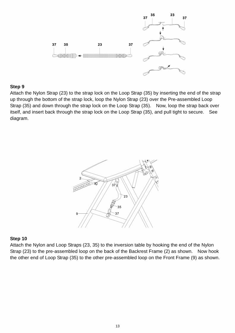
Step 9 Attach the Nylon Strap (23) to the strap lock on the Loop Strap (35) by inserting the end of the strap up through the bottom of the strap lock, loop the Nylon Strap (23) over the Pre-assembled Loop Strap (35) and down through the strap lock on the Loop Strap (35). Now, loop the strap back over itself, and insert back through the strap lock on the Loop Strap (35), and pull tight to secure. See diagram.
Step 10 Attach the Nylon and Loop Straps (23, 35) to the inversion table by hooking the end of the Nylon Strap (23) to the pre-assembled loop on the back of the Backrest Frame (2) as shown. Now hook the other end of Loop Strap (35) to the other pre-assembled loop on the Front Frame (9) as shown.
37
23
35
379
2
13

OPERATION AND ADJUSTMENTS For added safety, a nylon strap has been included to restrict the degree of inversion. This strap can be adjusted to different lengths to allow for a greater or lesser degree of inversion. To lengthen the Nylon Strap (23) feed the top end of Nylon Strap (23) into the strap lock, and pull on the lower end of the strap. To shorten the length feed the bottom end of Nylon Strap (23) into the strap lock, and pull
18
2
3
THE STRAP SHORTEN LENGTHEN
23 23
on the top end.
ADJUSTING THE BOOM
The Adjustable Boom (3) can be moved to a variety of different positions, in order to accommodate the height of the person on the inversion table. To adjust the Adjustable Boom (3) pull out the Adjustable Boom Knob (18), and slide the Adjustable Boom (3) up or down until the desired height on the height scale is positioned just below the Backrest Frame (2). When the Adjustable Boom (3) is in the desired position, simply release the Adjustable Boom Knob (18), slide the Adjustable Boom (3) slightly up or down until the Adjustable Boom Knob (18) locks into place.
14

THE HANDLEBARS
For added convenience and safety, a set of Handlebars (6) has been added to the inversion table. These Handlebars (6) are located at the top of the Rear Frame (8). The Handlebars (6) are there to help you return to the upright position from any degree of inversion. If you wish to return to the upright position, and the backrest is moving too slowly, or not moving at all, simply grab the Handlebars (6) and pull on them until you return to the upright position. NOTE: The inversion table should always return to the upright position when you move your hands below your waist. If it does not, the inversion table is probably not adjusted correctly to your height. * Always hold on to the handlebars and go back slowly. Failure to comply could result in serious
8
6
6
physical injury.
GENERAL PRECAUTIONS
1. It is recommended that someone be with you while you are using this inversion table for the first few times.
2. Make sure that the Front and Rubber Rear Heel Holders (13, 14) are holding your feet securely. 3. Make sure that the Adjustable Boom (3) is properly set to your height. 4. Make sure that the Adjustable Boom (3) is held securely by both the Adjustable Boom Knob
(18). 5. Make sure that there is enough room for the inversion table to rotate completely.
15

5
40
3
13
144
ADJUSTING THE FRONT AND RUBBER REAR HEEL HOLDERS
1. Pull up on the Adjustable Instep Frame Knob (40), slide the Adjustable Instep Frame (5) completely out of the Adjustable Boom (3).
2. Slide your ankles between the Front and Rubber Rear Heel Holders (13, 14) and stand on the Foot Bar (4) located at the bottom of the Adjustable Boom (3).
3. Pull up on the Adjustable Instep Frame Knob (40), allow the Adjustable Instep Frame (5) to slide back into the Adjustable Boom (3). Push in slightly on the Adjustable Instep Frame (5) until the Front and Rubber Rear Heel Holders (13, 14) are around your ankles. Release the Adjustable Instep Frame Knob (40) and adjust the Adjustable Instep Frame (5) slightly until the Adjustable Instep Frame Knob (40) locks into place.
4. Stand upright with your back against the backrest and your hands lowered at your sides.
BALANCING THE INVERSION TABLE The inversion table is like a very sensitively balanced fulcrum. It responds to very slight changes in weight distribution. So, it is very important to make sure that the height is adjusted properly. To do this, mount the inversion table, lock your ankles into the heel holders, and lie back with your hands at your sides. Slowly place you hands across your chest. While in this position, your head should still be above your feet. If your feet are above your head, dismount and adjust the height again.
USING THE INVERSION TABLE 1. Start by lying fully back on the backrest with your hands at your side, or resting on your thighs. 2. Keeping your hands close to your body begin to raise your arms slowly allowing the table to
rotate backward. Stop, or lower your arms to control the downward rotation of the table. 3. Raise your arms until they are over your head. At this point, the inversion table will be as far
back as it can go. 4. As you get more comfortable with the use, rock the backrest slowly by moving your arms up and
down slowly. 5. It is recommended that the inversion table be used for five or ten minutes each morning, and
again each evening. 6. Return to the upright position by slowly moving your hands back down to your thighs.
16
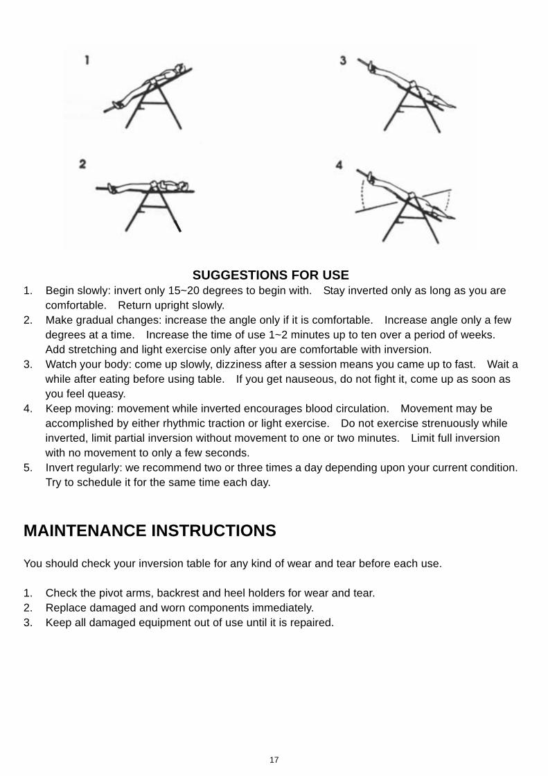
SUGGESTIONS FOR USE
1. Begin slowly: invert only 15~20 degrees to begin with. Stay inverted only as long as you are comfortable. Return upright slowly.
2. Make gradual changes: increase the angle only if it is comfortable. Increase angle only a few degrees at a time. Increase the time of use 1~2 minutes up to ten over a period of weeks. Add stretching and light exercise only after you are comfortable with inversion.
3. Watch your body: come up slowly, dizziness after a session means you came up to fast. Wait a while after eating before using table. If you get nauseous, do not fight it, come up as soon as you feel queasy.
4. Keep moving: movement while inverted encourages blood circulation. Movement may be accomplished by either rhythmic traction or light exercise. Do not exercise strenuously while inverted, limit partial inversion without movement to one or two minutes. Limit full inversion with no movement to only a few seconds.
5. Invert regularly: we recommend two or three times a day depending upon your current condition. Try to schedule it for the same time each day.
MAINTENANCE INSTRUCTIONS You should check your inversion table for any kind of wear and tear before each use. 1. Check the pivot arms, backrest and heel holders for wear and tear. 2. Replace damaged and worn components immediately. 3. Keep all damaged equipment out of use until it is repaired.
17

STORAGE
26
8 9
FOLDING THE INVERSION TABLE
For your storage convenience, the inversion table can be folded down to place against a wall, under a bed, or in a storage area. Pull out the Ring Pin (26) from the holes on the Rear and Front Frames (8, 9), then push the Rear and Front Frames (8, 9) together until they meet. Insert the Ring Pin (26) back into the hole on the Front Frame (9). Now the inversion table is ready to be stored, allowing you to unfold it quickly and easily whenever you want to use it.
18
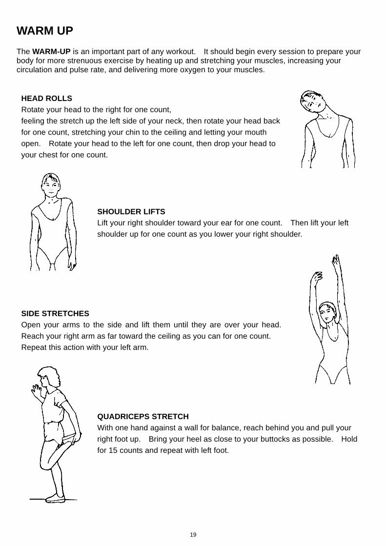
WARM UP The WARM-UP is an important part of any workout. It should begin every session to prepare your body for more strenuous exercise by heating up and stretching your muscles, increasing your circulation and pulse rate, and delivering more oxygen to your muscles.
HEAD ROLLS Rotate your head to the right for one count, feeling the stretch up the left side of your neck, then rotate your head back for one count, stretching your chin to the ceiling and letting your mouth open. Rotate your head to the left for one count, then drop your head to your chest for one count.
SHOULDER LIFTS Lift your right shoulder toward your ear for one count. Then lift your left shoulder up for one count as you lower your right shoulder.
SIDE STRETCHES Open your arms to the side and lift them until they are over your head. Reach your right arm as far toward the ceiling as you can for one count. Repeat this action with your left arm.
QUADRICEPS STRETCH With one hand against a wall for balance, reach behind you and pull your right foot up. Bring your heel as close to your buttocks as possible. Hold for 15 counts and repeat with left foot.
19

HAMSTRING STRETCHES Extend your right leg. Rest the sole of your left foot against your right inner thigh. Stretch toward your toe as far as possible. Hold for 15 counts. Relax and then repeat with left leg.
CALF/ACHILLES STRETCH Lean against a wall with your left leg in front of the right and your arms forward. Keep your right leg straight and the left foot on the floor; then bend the left leg and lean forward by moving your hips toward the wall. Hold, then repeat on the other side for 15 counts.
TOE TOUCHES Slowly bend forward from your waist, letting your back and shoulders relax as you stretch toward your toes. Reach as far as you can and hold for 15 counts.
INNER THIGH STRETCH Sit with the soles of your feet together and your knees pointing outward. Pull your feet as close to your groin as possible. Gently push your knees toward the floor. Hold for 15 counts.
20

IRONMAN PARTS REQUEST FAX FORM
Please fax this form to (1-626-810-2166)
OR YOU CAN EMAIL CUSTOMER SERVICE REQUESTS TO
[email protected] NAME: _____________________________________________________________________ ADDRESS: _________________________________________________________________
CITY ________________ STATE __________________ ZIP ________________ TELEPHONE: (Day) __________________________________________________________
(Night) _________________________________________________________ (Email Address) _________________________________________________
SERIAL#: ______________________________________________________ MODEL#: ______________________________________________________
PURCHASE DATE: ___________________________________________________________ PURCHASE FROM: ___________________________________________________________
PART # DESCRIPTION QTY
“YOUR ORDER WILL BE PROCESSED WITHIN 3 BUSINESS DAYS”
OFFICIAL USE ONLY
SHIP DATE: ___________________________________________ TRK #: _______________________________________________ BACK ORDER: ________________________________________
21
![English focus inversion constructions1 - asc.ohio …07-07-24)EFI_web.pdfEnglish focus inversion constructions1 ... [Quotative inversion] c. There are on the table a diverse selection](https://img.dokumen.tips/doc/110x75/5abed35e7f8b9aa15e8d4f8d/english-focus-inversion-constructions1-ascohio-07-07-24efiwebpdfenglish.jpg)


![English focus inversion - ling.ohio-state.edu › ~culicove › Publications › Focus inve… · [Locative inversion] (b) There is on the table a diverse selection of imported delicacies](https://img.dokumen.tips/doc/110x75/5f22fd074a0c4860122a342a/english-focus-inversion-lingohio-stateedu-a-culicove-a-publications-a.jpg)