Embed Size (px)
Citation preview

rr-r:f~r~~r..ilj~~1rl
.Published by the
V Institute of Electrical and Electronics Engineers. Inc
I EEE July 20, 1993 SH16410

Fourth Interim Collection1991-1993 NESC Interpretations
National Electrical Safety Code Committee, ASC C2
Fourth Interim Collection
of theNational Electrical Safety Code
Interpretations
1991-1993
Abstract: This edition includes official interpretations of the NationalElectrical Safety Code as made by the Interpretations Subcommittee of theNational Electrical Safety Code Committee, ASC C2.
Keywords: electric supply stations, overhead electric supply and com-munication lines, underground electric supply and communicationlines, clearances to electric supply and communication lines, strengthrequirements for electric supply and communication structures

Foreword
The IEEE C2 Secretariat regularly publishes InterpretationRequests received and Interpretations made by the NationalElectrical Safety Code (NESC) Subcommittee on Interpretations.The original requests have been lightly edited to remove extraneousmatter and focus on the C2 problem presented. Some illustrationshave been redrawn for publication. With these exceptions, requestsare in the form received.
The first volume, INTERPRETATIONS 1961-1977, published in1978, included the first interpretation request received for the 6thEdition of Part 2 (m 92, May 1961) and ended with the last inte~tation issued in 1977 (IR 212). The second volume, INTERPRETA-TIONS 1978-1980, continued with IR 213 issued in 1978 and endedwith the last i~~TPretation issued in 1980.(IR283). It also includesall interpretations found in the archives and applying to the 5th andprior editions of the Code (IR 11 through IR 90). Where no copy ofan interpretation Tequest or an interpretation could be found in thearchives, this fact is noted. The third volume, INTERPRETATIONS1981-1984, continued with IR 284 issued in 1981 and ended withIR 361 issued in 1984. It also contains requests IR 362 to IR 366, butdid not include their interpretations, as the InterpretationsSubcommittee still had them under consideration at press time.INTERPRETATIONS 1984-1987 incorporated IR 362 to IR 366with their interpretations, continued with IR 367, issued in 1984, andended with IR 415,wbich was requested in 1987. The nextwlmne,INTERPRETATIONS 1988-1990, incorporated interpretations forIR 407, IR 413, and IR 414, which were not included in the previousvolume, and included;nterpretation requests to IR 443.

The First Interim Collection 1991-1993, provided interpretationsfor IR 442 and IR 443, which were still under consideration at presstime of the previous volume, and incorporated interpretations forIR 444 through IR 447. The Second Interim Collection 1991-1993provided interpretations for IR 448 through IR 453.
The Third Interim Collection 1991-1993, incorporated aninterpretation for IR 454 and provided interpretations for IR 455through IR 462. IR 463 through IR 467 were included, although theinterpretations were under consideration.
This volume, the Fourth Interim Collection 1991-1993, providesinterpretations for IR 463 through IR 467, and incorporatesinterpretations for IR 468 through IR 470. IR 471 through IR 474are included although interpretations have not yet been providedfor them.
The Secretariat hopes that the publication of all interpretationswill prove helpful to those concerned with the NESC.

Procedure for Requesting an Interpretation
Requests for interpretation should be addressed to:
Secretary for InterpretationsNational Electrical Safety Code Committee, ANSI C2IEEE Standards Office445 Hoes LaneP.O. Box 1331Piscataway, NJ 08855-1331
~uests for interpretations should include:
1. The rule number in question.2. ~he applicable condit~s for the case in question.
Line drawings should be black ink or excellent black penciloriginals. Photos should be black-and-white glossy prints. Theseillustrations must be reproduced for committee circulation andeventually will be used to supplement the text of our next edition.Clear diagrams and pictures will make the work of interpretationeasier and more valuable to C2 users.
&quests, including all supplementary material, must be in a "formthat is easily reproduced. If suitable for Subcommitteeconsideration, requests will be sent to the InterpretationsSubcommittee. After consideration by the Subcommittee, whichmay involve many exchanges of correspondence, the inquirer willbe notified of the Subcommittee's decision. Decisions will bepublished from time to time in cumulative form and may be orderedfrom IEEE.
Inte~pretations are issued to e~lain and clarify the intent ofspecific rules and are not intended to supply consulting informationon the application of the code. The Interpretations Subcommitteedoes not make new rules to fit situations not yet covered.

Contents
Section 9. Grounding Methods for Electric Supply andCommunications Facilities 7
Part I. Rules for the Installation and Maintenance of ElectricSupply Stations and Equipment 9
Part 2. Safety Rules for the Installation and Maintenance ofOverhead Electric Supply and Communication Lines 12
Part 3. Safety Rules for the Installation and Maintenance ofUnderground Electric Supply and Conununication Lines 25
Part 4. Rules for the Operation of Electric Supply andCommunications Lines and Equipment 27

97D 97D
Section 9.Grounding Methods for Electric Supply
and ColnInunications Facilities
Rule 97D
Separation of primary and secondary neutrals on a multiple-grounded system
REQUEST (Sept. 23, 1992) IR 466in recent months some farmers have expressed concern that the
separation of primary and secondary neutrals on a multiple-grounded system as outlined in Rule 97D2 is inadequate. These
--farmers assert that earthculTents are accessing their dairy catt1e viathe primary multiple-grounded system and specifically thegrounqing conductor and elect.rade.at the transformer .
I have been requested to obtain an interpretation from theNational Electrical Safety Code Committee relative to installing a~z:ounding conductor and .electrode "at the transformer locationsonly for the primary arrestor and tank grounding. The primaryneutral would then be grounded one span (approximately 300 ft)from the transformer. The primary and secondary neutrals wouldbe separated bya spark gap or device with a breakdown voltage notexceeding 3 kV and the secondary neutral will have a separategrounding electrode as outlined in Rule 97D2.
1. Is the above arrangement allowable as outlined in Rule97D2 and to reduce Qbjectionable current flow in thegrounding conductor as outlined in Rule 92D?
2. Does the above arrangement still meet the requirements ofan effectively grounded neutral as indicated in the Defini-tions and a multiple-grounded system as in Rule 96A3 if theutilities continue to install a minimum of four grounds permile?

97D
3.97D
Since the last span may be considered a single-groundedsystem, should the grounding connection on the secondaryneutral be located at least 20 ft from the surge arrestorgrounding electrode as in Rule 97Dl?
INTERPRETATION (Jan. 19, 1993)This request for information is concerned with separation of
primary and secondary neutrals to reduce earth current flow.However, the proposed system does not meet NESC requirements,primarily because the multiple-grounded neutral (termed primaryneutral in the request for interpretation) is not grounded at thetransformer pole as required by Rule 96A3.
Answers to specific questions are:1. No. The primary neutral must be grounded at the
transformer pole as required by Rule 96A~.2. No, see answer to question 1. Also, Rule 21581 requires that
a common neutral be effectively grounded. Thisrequirement is site specific; it may require more than fourgrounds per mile (see also definition of effectivelygrounded).
3. The last span of the proposed system is still part of a multi-grounded system; it may not be treated as a single-groundedsystem. Consequently, Rule 97Dl does not apply. UnderRule 97D2, the secondary neutral grounding conductormust be insulated for 600 V, and its electrode must not beless than 6 ft from the primary neutral and surge arrestergrounding electrode.
NOTE: Rule references in this response are w the 1990 Edition, followingthe format in the request for information. The referenced requirementsremain the same in the 1993 Edition.
8

127L 127L
Part I.Rules for the Installation and Maintenanceof Electric Supply Stations and Equipment
Rule 127L, Table 127-5
Hazardous area ratings for natural gas
REQUEST (Oct. 5, 1992} IR 467Review of Rule 127L of the NESC concerning hazardous area
ratings for natural gas indicates that there are several industrypractices that do not appear to be in strict compliance with the re-quirements of this rule. Your response to the following questions isrequested.
1. Based on industry practice, the use of low-pressure naturalgas for building heating C5psig or less} does not seem to re-quire the building to be rated as a hazardous area. Table 127-5 does not put any limitation on the gas pressure. Accordingto this table, the building would have to be rated Class I, Di-vision 2, Group D, because the gas piping contains screwedconnections and valves. Can buildings using natural gas at5 psig or less for heating, and containing natural gas heatersand piping with screwed or flanged connections, not berated as hazardous (Class I, Division 2, Group D} solely be-cause of the natural gas pipe and heating equipment?
2. A generation building of approximately 1 000 000 ft3 con-tains a natural gas pipeline operating at 550 psig or less. Thenatural gas pipeline passes through the building. The build-ing has power roof ventilators, louvers, supply fans, androll-up metal doors 1hatare used for ventilation; however,the amount of ventilation provided will depend upon theoutdoor ambient temperature and the amount of heat beinggenerated within the building. The pipeline is all weldedconstruction except for one ANSI Class 300 raised faceflange. The flange is required at the point where the gaspipeline exits the ground in order to provide electrical sepa-ration between the below and above grade pipe for cathodicprotection purposes. Does the presence of this one flange inthis building require the entire building plus any connected
9

127L
3.
4.
5
127Lbuildings that share a non-gas tight wall with this building,and 15 ft beyond any wall or roof ventilation louver on thisbuilding or the connected building, to be rated Class I, Divi-sion 2, Group D?Question no.3 is identical to question no.2, except the flangeon the pipeline is contained within a small enclosure that hasweather boots at each pipe penetration into the enclosureand the enclosure has a 2-in vent pipe connected to the top ofthe enclosure and extended outside the building.A generation building as described in question no.2 containsa combustion turbine that burns natural gas. Thecombustion turbine is contained within a separate enclosureinside the building. Natural gas piping, valves, fitting, andconnections to the combustors are contained within thecombustion turbine enclosure. The combustion turbineenclosure has natural gas detectors that alarm and then shutoff the gas turbine and the gas supply at levels below theignitible level of natural gas. The combustion turbine has apositive pressure ventilation system. All penetrations intothe enclosure are sealed sufficiently to hold in the CO2discharge in the event of a fire. The discharge of ventilationair is through a louver into the generation building. Is thecombustion turbine enclosure a Class I, Divisioa2, Group Darea, or a nonhazardous area? Is the entire larger generationbuilding a Class I, Division 2, Group D area?This question is identical to question no.4, ~Kcept theventilation air discharged from the combustion turbineenclosure is ducted outside the larger generation building.
10
127L 127L
INTERPRETATION (January 19, 1993)The answers to your specific questions are:I. Rule 127L only identifies the areas where the requirements
of ANSI/NFPA 70-1987 (NEC), Article 500, must be ~pplied.It is the responsibility of the designer to determine whatrequirements, if any, are specified by Article 500 for lowpressure gas used for building heating. The NESCInterpretations Subcommittee is not empowered to interpretNEC requirements.
2-5, inclusive:Table 127-5 covers nonfired areas containing gas pipelineconnections, valves or gauges for indoor locations withadequate ventilation. All of these questions appear to relateto different design methods used to obtain "adequate"ventilation. The Interpretations 'Subcommittee does notsupply consulting information nor does it approve specificdesigns.
For information purposes only, note that NEC Article 500-2, FPNNo.3, indicates that "Through the exercise of ingenuity in the layoutof electrical installations for hazardous (classified) locations, it isfrequently possible to locate much of the equipment in lesshazardous or in nonhazardous locations and thus to reduce theamount of special equipment required "
11

232D4232D4
Part 2.Safety Rules for the Installation and
Maintenance of Overhead Electric Supply andCommunication Lines
Rule 232D4, Table 232-1, Footnote 8
Exceptions to Vertical Clearance Limits for Cables AboveGround
REQUEST (Dec. 15, 1992) IR 470Footnote 8 of Table 232-1 states, "Where the height of attachment
to building does not permit service drops to meet these values, theclearances may be reduced to the following:..."
Our publici)el'V~ oompany uses an insulated tripl~x servicecable for 120/240 volt service to homes. The cable meets therequirements of Rule 230C3. We allow for a 1 ft drip loop below theservice point of attachment to a single family residence at shown inFigs IR 470-1 (a) through (d) and 470-2.
On new oonstruction, we could require the point of attachment tobe at elevation 13.0 ft so that the drip loop height is 12.0 ft in order tocomply with the 12.0 ft in category 5 of Table 232-1. Alternatively,we could require that point of attachment at 11.5 it so that theservice drop and drip loop comply with Table 232-1, items a and c inFootnote 8.
Clarify the meaning ofa-s not permit. This could mean anythingfrom inconvenient to economically burdensome to almostimpossible. Is it the intent of the NESC to routinely allow or condonea drip loop clearanre.ofl'<':5ft, as is allowed by the 1993 NationalElectrical Code (NEC) in 230-24?
12

232D4 232D4
TYP1(AlA006E
CONSTRUCTNJN
TYPICAL CON(qETE
8LOCl< OR
STRUCT~AL CLAYTI-E
CONSTRUCTION
s;]~TYPOCAL FRAMECONSTRUCTION
~/On
()A
fyf ,
Pf'f
"..,
0.
EyE8D. T
-rrj I ::.-q-19~ ,
TO GROLo.o LEVEL TO GROLo.o LEVEL
NOTES: (1) Contact customer service representative for height of service attachmentpoint if service crosses driveways.(2) Service attachment to the building shall be designed to withstand 330 Ibs tensionapplied at the point of attachment.(3) Pipe strap shall be firmly attached to wall at intervals of30 in minimum.(4) Drip loop maximum 1 ft below point of attachment(5) EMT may be used provided the point of attachment is not on the conduit. Araintight hub is required for use with EMT .
I~I
Fig m 470..1 (a) -(d)
13
232D4 232D4
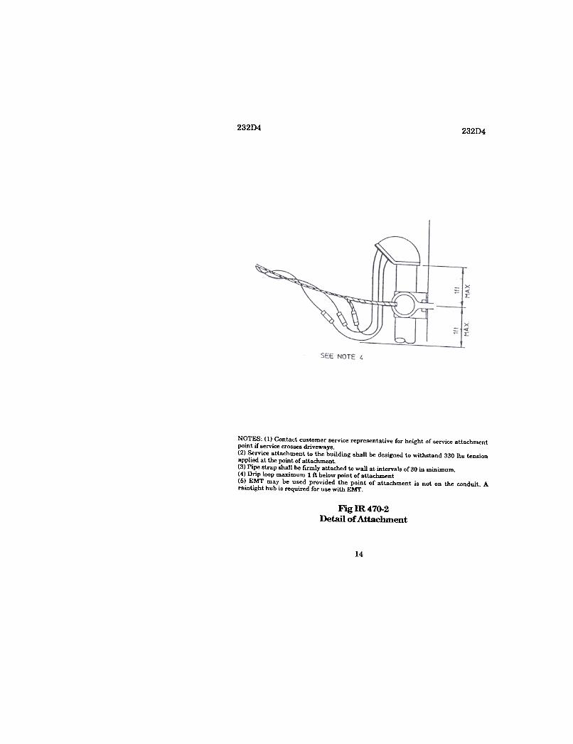
NOTES. (I) Contact customer service representative for height of service attachmentpoint if service crosses driveways.(2) Service attachment to the building shall be designed to withstand 330 Ibs tensionapplied at the point of attachment.(3) Pipe strap shall be rlrmly attached to wall at intervals of 30 in minimum.(4) Drip loop maximum I ft below point of attachment(5) EMT may be used provided the point of attachment is not on the conduit. Araintight hub is required for use with EMT.
Fig m470-2Detail of Attachment
14

23204 23204
INTERPRETATION (March 25, 1993)The answer to your question is no, it is not the intent of the NESC
to routinely allow or condone the reduced clearances stated inFootnote 8 ofTable 232-1.
Application of Footnote 8 is limited to cases "where the height ofattachment to a building. ..does not permit service drops to meetthese values. .." (as given in Table 232-1, Item 5). Table 232-1clearances are required if the building being serviced is high enoughso that the attachment may be made to the building without theneed for a service mast (such as two-story or gable-roofed houses).Footnote 8 may be used with discretion on low buildings (such asflat or hip-roofed houses), either to avoid the use of a service mast orto limit the height of a mast where a mast is necessary.
15

235C2b235C2b
Rule 235C2b
Conductors of different sags on same support
IR 474REQUEST (April 26, 1993)
Our question involves vertical clearance between the phase wireand the neutral wire of a 12.47/7 .2 kV distribution circuit. Thevoltage between conductors is nominally 7.2 kV. We understand thebasic clearance requirement to be 16 in per Rule 235C1, Table 235-5.
Rule 235C2b(1)(a) applies to conductors of different sags on thesame support. We are using conductors of the same size and sagwhen installed. However, when one conductor has ice and the otherdoes not, the two conductors"n61onger have the same sag.l~ it theintent to apply Rule 235C2b(1)(a) to this condition when the twoconductors involved are of the identical size and type, and areinstalled at the same tension and sag?
In our situation, on a typical distribution vertical single-phasestructure, the phase-to-neutral vertical spacing is about 4 £1.Application of Rule 235C2b(1)(a) to this type of structure severelylimits its span capacity.
INTERPRETATION
(In process)
16

442E 442E
.Neither procedures which prohibit operation of equipmentor switches without authorization from the designated person(Rule 442A) nor permanently installed tags satisfy thetagging requirements contained in Section 44. Individuallyinstalled tags, are required to identify switching/controlpoints that must be kept in a specific position to provideworker protection (usually, but not always, in an abnormalposition). Also, the tags should be removed when workerprotection is no longer required (see Rule 444G). Theprocedures are clear for de-energizing equipment or lines forwork; the same de:gree of protection is required in thesituation under consideration in order to prevent (a) re-activation of reclosing controls, and (b) automatic, manual or
,remote closing ofthe,associated switch if it trips ()ut duringthe protected work operation.
It should be noted that the above statement is not intendedto be critical of either (a) procedures that prohibit operation ofequipment or switches without authorization from the
"designated person,()r{b)use of permanently insta:ned tags forinstruction purposes. However, neither can be used to satisfythe tagging requirements of Section 44..Remote control systems, such as SCADA, may be used toimplement switching and/or tagging operations, providing
,that the system operates in a fail-safe manner. To qualify, ~SCADA system must be able to both verify that the intendedoperation has actually taken place and ensure that theintended operation win not change if the SCADA system losespower or otherwise becomes disabled. In this case, theBCADA system .must be able to verify that the automaticreclosing control has been rendered inoperative and ensurethat it will remain so, and/or verify that the SCADA tag is in,place and ensuretbat it will remain so. This Tequirementwould appear to disqualify electronic tags. Also, SCADA ta:gsmust meet all OSHA requirements.
34

442E 442E
Based on these principles, the answers to the specific questionsare:
For IR 463
1.
2.
3.
4.
5.
This option does not meet requirements.This option appears satisfactory , providing that the statedoperations are both verifiable and fail-safe. We understandthe statement to mean that both reclosing and local breakercontrol will be rendered inoperative via SCADA during a hotline hold operation, such that local operation or restoration isimpossible.This option does not meet the full intent of Rule 442E2. Tagsare required to prohibit reclosing after a trip until thedesignated person can determine that such reclosing will n6tbe harmful to the protected party. While this option wouldeliminate automatic reclosing, tagging is still required forthose instances where reclosing after a trip is prohibited forworker protection during specified work operations.This option appears satisfactory , providing that the taggingoperation is both fail-safe and verifiable. We understand thestatement to mean that reclosing will also be deactivated,again in a verifiable and fail-safe manner.This option is not satisfactory .Because a lamp can burn out,it is not a fail-safe operation -a lamp cannot be used as asubstitute for a tag.
For IR 464
This operation, as described in "Point," appears satisfactory (seeIR 463, #2, including qualifications). Note that an electronic tag maynot be substituted for a "normal" tag unless the electronic system isfail-safe; if it is not fail-safe and used, it should be treated as asupplementary warning.
The Interpretations Subcommittee has not analyzed the schematicincluded with the request for interpretation. Such action wouldconstitute consulting advice beyond the scope of the Subcommittee.
35

442E442E
Summary
The introduction of remote control systems does not change thebasic requirements and procedures for worker safety. Such systemsmay be used only when they provide equivalent protection in a fail-safe manner .
36

239G
Rule 239G
239G
Electrical conductors in climbing space on joint-use utilitypoles
REQUEST (September 15, 1992) IR 465I have been requested to seek advice and interpretation of current
NESC rules regarding electrical conductors in climbing space onjoint-use utility poles. There has been much concern among tele-phone and CATV employees that the current practice of installingtemporary electrical drops in climbing space presents excessivehazards to those climbing tlle poles. Therefore, I am requesting yourassistance in providing a ruling on this issue.
The enclosed photographs (Figs IR 465-1-465-6) depict typicaltemporary power instanations throughout the area concernedconsisting of triplex conductors suspended freely from thetransformer secondary splice to the weatherhead placed toward thebottom of the pole. As you can see, the conductors are somewhatloose in the climbing space and, according to some, create aooRsiderable exposure hazaro to those climbing with "hooks." Onephoto (Fig IR 465-3) exhibits an attempt by a communicationsworker to tie back the triplex so that it would not be adjacent to hisworking area on the pole.
The position of the local electric utility is that these installationsare in accordance with the NESC rules in that the multiconductorsare jacketed and require no extra protection as specified in Rule239G2. The communication companies in the area believe that if infact this service drop requires no extra protection, it still would re-quire being fastened taut on the pole as specified in Rule 239G4b. Italso appears that Rule 239E2c addresses the issue of attaching theSecQndaryC()nductorsw the ,gurface of the pole. The local electricutility does not agree with this.
Please provide your recommendations on these issues:1. Does Triplex =nstitute a jacketed multiconductor cable
requiring no extra physical protection in verticalinstallations as referred to in the NESC Rule 239G2?
2. Is Triplex exempted in any way from being securely fas-tened through climbing spaces as specified in NESC Rules239E and 239G?
17

2390 2390
3. Are the construction methods depicted in Figs IR 465-1-465-6 in accordance with NESC rules and regulations?
Figs m 465-1 and m 465-2
18


2390 2390
INTERPRETATION (Dec. 8, 1992)This request for interpretation concerns electric supply
conductors in the climbing space of jointly used utility structures.Rule 239G, covering supply conductors in communication space,appears to be the primary rule in question. Rule 239E is limited tosupply space, and Rule 239G4b applies only to street lighting lampleads.
Triplex, as used in this IR and as illustrated in the photographs, isa generic term for a low-voltage (less than 600 V) three-conductorsupply cable consisting of two insulated conductors and a bareneutral, with the individual conductors loosely cabled together. Assuch, it is covered under Rule 239G7, Multiple-Conductor Cables. Incontrast, a jacketed multiple-conductor cable (Rule 239G2) is onewith a single jacket enclosing the entire cable assembly.
Vertical run~ ~f triplex cable may be made throughcommunication space under the provisions of Rule 239G7. Thecable must be protected by a nonmetallic covering in thecommunication space (see also IR 439 -March 22, 1990). Inaddition, the triplex cable must be attached to the structure throughthe entire communication working space; it may not leave thestructure as an aerial service with 40 in above or belowcommunication attachments.
It should be noted that vertical runs may not obstruct either theclimbing or the working space, nor may they interfere with the safeuse of pole steps (Rules 237C and 2398). Also, vertical cable runs inthe climbing space must be both securely attached to the structureand protected with nonmetallic covering (Rule 236H). Whilejacketed cables do not require nonmetallic protection incommunication space under Rule 239G2, this applies only if thevertical run is not in the climbing space.
Answers to your specific questions are:1. Triplex is not a jacketed multiconductor cable; Rule 239G2
does not apply.2. No.3. The photographs show construction that does not appear to
be in accordance with NESC requirements.
20

280Alb280A1b
Section 28 (NESC, 1984 ed.) Rule 280A1b
Climbing Requirements for Structures for Overhead Lines
REQUEST (April 8, 1993) IR 472This request involves Rule 280Alb in the 1984 NESC edition.The structure in question is shown in Fig 472-1. This structure
was constructed in 1894 to provide area lighting. Additionally, overthe past thirty years, it has been utilized as a supporting structurefor a three-phase 15 kV distribution line in a residential area. Thiswas accomplished by bolting a spool insulator for the neutralconductor and a cross arm for the three primary conductors to twoof the vertical members of the lattice structure.
In Fig 472-2, the lattice-type structure supported by a singletubular steel support is shown. The tubular support isapproximately 24 1/4 in in diameter. The distances from groundlevel to the bottom of the support arms and additional distance tothe first horizontal cross member are noted.
Please provide your response to the following questions:1. Does this structure meet the definition of a "readily
climbable" structure?2. Is this structure a "closely latticed pole or tower"?3. Does the proximity of the stop sign as shown in Fig 472-3
modify your interpretation if it is possible for the stop sign tobe used to access the upper lattice area of the structure?
21


280Alb 280Alb
15'-11 112"1
-L~~=====j '\r--
6r~~J'-9"
,1, \
1!II
II.I/
14"-8 1/2"
10.-5"
I
Fig 472-2Column Base Elevation
23

280Alb 280Alb
~
r-- 2'-5"r;; OP ~ TOWER COLUMN
SIGN 4'-'/2"7'-'- --J
L: L:::,,-8"
>-«3::o«O0:=
SIOEWAlK
Fig 472-3Plan View of Location
INTERPRETATION
(In process)
24

350G 381G
Part 3.Safety Rules for the Installation and
Maintenance of Underground Electric Supplyand Communication Lines
Rule 350G
Markings on direct-buried cable
REQUEST (Feb. 26, 1993) IR 471Rule 35OG states that "all direct-buried jacketed supply cable
meeting Rule 35OB and all direct-buried communication cables shallbe legibly marked..."
Clarification is requested as to whether the marking defined inRule 35OG applies to communication service drops. The buriedservice drop is a wire typically o.275mtoo.350 in in diameter thatconnects a communication cable to users of services on that cablefrom a pedestal or terminal interface to that cable. Does Rule 35OGapply to the communication service drops?
INTERPRETATION
(In process)
Rule 381G
Requirement for barriers securing live front transformers inexcess of 600 V
REQUEST (Nov. 25, 1992) IR469Rule 381G2, Pad-Mounted Equipment states, "Access to exposed
live parts in excess of 600 V shall require two separate consciousacts. The first shall be the opening of a door or barrier that is lockedor otherwise secured against unauthorized entry. The second actshall be either the opening of a door or the removal of a barrier ."
25

381G 381G
My situation involves a locked fence surrounding both a waterpumping station and a live front transformer in excess of 600 V.The transformer has a single door that when lifted, fully exposes thehigh-voltage and low-voltage compartments. Since the fenceimpounds both utilities, would the fence constitute the first barrieror door for the transformer under Rule 381G2?
INTERPRETATION (April 19, 1993)This situation involves a single door, live front transformer
located within a fenced area; the fence is locked (presumably toprohibit unauthorized entry).
Rule 381G covers access to pad-mounted equipment. Rule 381G 1states that all pad-mounted equipment not fenced or otherwiseprotected shall be either locked or otherwise secured (regardless ofvoltage). Rule 381G2 states that two separate acts are required togain access to exposed live parts over 600 V. Both parts of the rulemust be taken as a whole; they are not separable..Consequently,Rule 381G does not require two separate barriers on a live fronttransformer with exposed live parts in excess of 600 V where thetransformer is located within a locked fenced area.
Rule 381G was added to the NESC in the 1973 Edition, as a singlerule without subparts 1 and 2. The requirement for two separateprocedures to gain access to exposed live parts in excess of 600 vwas clearly limited to pad-mounted equipment that is not locatedwithin a fenced or otherwise protected area. However, the rule didnot require that pad-mounted equipment with exposed live parts of600 V or less be locked. Consequently, the rule was revised to itspresent form in the 1987 Edition. The intent was to require that allpad-mounted equipment not located within a fenced or otherwiseprotected area be either locked or secured against unauthorizedentry; it was not the intent to require two separatepc(){/edures forequipment located within a fenced area.
It should be noted that this interpretation makes no determinationas to the suitability of the fence in the subject Case;,todoBOwouldconstitute consulting advice that the Interpretations Subcommitteecann!:,t provide.
26

381G 381G
My situation involves a locked fence surrounding both a waterpumping station and a live front transformer in excess of 600 V.The transformer has a single door that when lifted, fully exposes thehigh-voltage and low-voltage compartments. Since the fenceimpounds both utilities, would the fence constitute the first barrieror door for the transformer under Rule 381G2?
INTERPRETATION (April 19, 1993)This situation involves a single door, live front transformer
located within a fenced area; the fence is locked (presumably toprohibit unauthorized entry).
Rui~"381G covers access to pad-moubted equipment. Ru1e'J81Glstates that all pad-mounted equipment not fenced or otherwiseprotected shall be either locked or otherwise secured (regardless ofvoltage). Rule 381G2 states that two separate acts are required togain access to exposed live parts over 600 V. Both parts of the rulemust be taken as a whole; th~y areJlot separable. Consequently,Rule 381G does not require two separate barriers on a live fronttransformer with exposed live parts in excess of 600 V where thetransformer is located within a [()CMd fenced area.
Rule 381G was added to the NESC in the 1973 Edition, as a singlerule without subparts 1 and 2. The requirement for two separateprocedures to gain access to exposed live parts in excess or 600 vwas clearly limited to pad-mounted equipment that is not locatedwithin a fenced or otherwise protected area. However, the rule didnot require that pad-mounted equipment with exposed live parts of600 V or less be locked. Consequently, the rule was revised to itspresent form in the 1987 Edition. The intent was to require that allpad-mounted equipment not located within a fenced or otherwiseprotected area be either locked or secured against unauthorizedentry; it was not the iDteDt1or~uire two separate procedures forequipment located within a fenced area.
It should be noted that this interpretation makes no determinationas to the suitability of the fence in the subject case; todoBO wouldconstitute consulting advice that the Interpretations Subcommitteecannot provide.
26

442E 442E
Part 4.Rules for the Operation of Electric Supply and
Communications Lines and Equipment
Section 44, Rule 440
Definition of supply employees
REQUEST (Nov. 30, 1992) IR 468Define supply employees, specifically as applied to generatingstation electricians employed by an electric utility company.
INTERPRETATION (March 25, 1993)Employees of an electric utility company are referred to as supply
employees in the Part 4 Work Rules. This includes generatingstation electricians employed by an electric utility company. Section44 rules apply to the extent that such employees are doing workcovered by these rules.
Rule 441
Voltages of energized conductors or parts
REQUEST (April 8, 1993) IR 473The voltage references in Table 441-1 are phase-to-phase
voltages. The voltage references in the text, particularly in Rule441A1, do not specify whether the voltage is phase-to-phase orphase-to-ground. By definition, voltage, unless indicated otherwise,
"is phase-to-ground; however, the text also refers to Table 441-1,which clearly contains phase-to-phase voltages.
I am requesting that an interpretation be rendered that would'clarify the identification of voltage references in the text of Rute 441.
INTERPRETATION-(In process)
27

442E 442EUse of Supervisory Control and Data Acquisition Systems(SCADA) to tag electric supply circuits
REQUEST (July 1, 1992) IR 463Rule 442E of the 1993 edition has been changed in part to read:
"2. Controls that are to be deactivated during the course ofwork on energized or de-energized equipment or circuitsshall also be tagged. Tagging of Supervisory Control andData Acquisition Systems (SCADA) in itself shall not beconsidered sufficient. A physical tag is required to belocated at every switch, breaker, or like device fromwhich operation via SCADA of equipment is possible."
Previous1y interpretation request numbers IR 433 and 434 wereissued on this matter, which indicated that the intent was to require.tagging.OR all ooatr.ols,OOth" looal"andremote, from"whlchN-energization of a line or piece of equipment was possible. The intentof the revised rule seems confusing once again.
.The conditiunin question is when -qua1ified personnel are workingon or near energized lines or equipment and the feature of automaticreclosing on fault-protecting breakerslreclosers is disabled; we termthis a hotline hold: in the event of a tripout, the switching authorityobtains a release from the crew prior to directing re-energization.
At one time we had relied on our operating rules that require allpersonnel to obtain authorization from the switching authority priorto operating any controls or switches; i.e., we were tagging only theSCADA.cantrJJ1s. and this worked without incident for many years.A couple of years ago, we added permanently installed hot line holdtags on all SCADA-controlled breakers in an attempt to meet codeby proyiding 16C81 'wRn\ingnot to 'Operate without authori~ation.These permanent tags read: "Caution. Hot Line Hold Order may bein effect on this circuit. Do not place in local position unless re-quested by Operator ." Based (tR the previously 'ref~enced
28

442E 442E
interpretations, we were considering the modification of localbreaker controls such that local closing capability was disabledduring a hot line hold (at the same time automatic reclosing wasdisabled). As a result we felt that tagging during our hot line holdswould be done on the only controls from which re-energizationcould occur, i.e., only on SCADA. This approach was to have beendone using the same latching relay now used to disable automaticreclosing, such that loss of power or loss of SCADA communicationswould not change the status of local closing control or of automaticreclosing. Now we are unsure of the intent of the revised rulerequiring local tagging. If SCADA controls are the only point ofclosing control remaining in effect, how -do local tags provide forworker safety?
I agree that such local tagging is prudent and necessary for de-energized work, when not only brea~!'S but also disconT\~ctswitches are open and motor operators are also uncoupled. It seemsthe revised language applies most when ~orking on de-energizedlines (as detailed fully in NESC Rule 444C) rather than to energizedwork; perhaps rules for work on energized and de-energized facili-ties should be kept separate and distinct from one another.
The requirement for local tagging during hot line holds may infact result in some adverse safety effects. The NESC does not re-quire that automatic reclosing be disab~ when workers performenergized work, so rather than wait for the time necessary to placelocal tags, the fear is that some may choose to work with automaticreclosing enabled.
If our breakers had no automatic reclosing feature, then no con-trols would be deactivated during energized work, and no taggir!cg(local or SCADA) would be required, and yet the l('Cal breaker con-trols could conceivable be operated to re-energize. This seems to bean inconsistent requirement.
29

442E 442EIf as in our organization, the disabling of reclosing and the opera-
tion of breakers will be done predominantly via SCADA, the localtags during a hot line hold provide no warning to the control centeroperator; only the SCADA tag provides that. Our operating restric-tion requiring authorization prior to switching covers the local pos-sibility of breaker closing.
In our effort to meet the intent of the revised code, we areconsidering several options:
L Continue to count on permanently installed tags on eachbreaker's local control panel, warning to obtain authoriza-tion prior to operating any equipment, without adding anyother tags each time a hot line hold is issued,i,~.,'t'aggingonly SCADA controls since that is the control we normallyuse.
2. Change control wiring schemes, using the1at,(;hingrelaywdeactivate all local breaker closing controls at the same timethat the reclosing feature is disabled via SCADA and tagonly the SCADA controls during hot line holds.
3. Remove all reclosing relays from service such that no tag-ging (either local or SCADA) is required during energizedwork since no controls will be deactivated.
4. Replace our locaVremote control switches on breaker panelswith a new type that includes a tagging f1agfeaturew pro-vide a warning locally when a hot line hold is implementedvia SCADA.
5. Add a warning lamp to breaker panels that would serve asthe local warning tag, i.e., turned on when the reclosing fea-ture is deactivated via SCADA command.
I am unsure which of these options would meet the intent of therevised rule as presently written and would appreciate someclarification to help guide us in this matter.
INTERPRETATION
NOTE: A single response is given for IRs 463 and 464 because theserequests for interpretations raise overlapping concerns. See theinterpretation for both IRs 463 and 464 following IR 464.
30

442E 442E
Rule 442E
Use of Supervisory Control and Data Acquisition Systems(SCADA) to tag electric supply circuits
REQUEST (July 10, 1992) IR 464This request for interpretation is in regard to the 1990 NESC Rule
442E, Tagging Electric Supply Circuits (paragraph 1, secondsentence), "Controls that are to be deactivated during the course ofwork on energized or de-energized equipment or circuits shall a1sobe tagged. The tags shall be placed to identify plainly the equipmentor circuits on which work is being performed." Paragraph 2 followsW1th:«Tagging o'f'Supervisory Control and Data AcquisitionSystems (SCADA) in itself shall not be considered sufficient."
.As a result of.paragr.aph2,~portion of the benefit realized fromthe installation of a SCADA system is diminished, namely, the timeand cost factor of sending a switchman to the location to install tagson,8witches pre~siy'()perated by the system. Case in point: whenperforming any energized work on transmission or distributioncircuits, safety procedures require the reclosing devices to be turnedoff during this work:'Priorto Rule 442E, our SCADA system wasutilized for this purpose, including the tagging of the device inSCADA. Our switching and tagging procedures do not allowoperation of switches or equipment without authorization from theappropriate operator; therefore, the practice worked very well.
In an effort to regain some of the cost incentive features. wewould propose the following comments for consideration by theCommittee.
31

442E 442E
Point: If the circuit that normally provides the reclosing voltage tothe closing circuit of breakers were rendered inoperative, a personcould not close a breaker from any manually operated controlswitch located at the substation control room or the breaker itselfwithout first turning control voltage onto the closing circuit for thatbreaker via SCADA. Would the device, rendered inoperative, andthe electronic tag placed in SCADA become sufficiently safe as thepresent Rule 442E provision provides?
We understand that all companies must apply this rule to the op-eration of their electrical system, and the effect is relative to proce-dure and degree of automation in place. We believe this modifica-tion does produce a positive desirable result for the safety of el~tricutility workers, and will help to minimize the increases in operatingcosts.
We are committed to safety and system reliability in-the-electricalpower industry and realize the tremendous impact that advancedtechnology has made. We are confident that an automated solutionis possible, one in which total safety and economics are provided for.
In regards to our telephone conversation on July 23, 1992, con-cerning the 1990 edition of the NESC Rule 442E, please find the en-closed schematic drawing showing the installation of a remotelyoperated contact that provides interruption of the closing circuit'spower supply. This feature does not allow any closing of .the devicefrom the panel or the breaker. However, the intent of the rule toprovide a warning to anyone at the substation is not achieved eventhough an operation to close would have no effect. In addition to thepower cutoff contact, new developments in electronic tags forremote operation are available.
We are actively pursuing this approach in order to maintain thefull benefit of our SCADA equipment.
32

442E 442E
INTERPRETATIONBasically, both IRs 463 and 464 involve tagging procedures when
SCADA systems are used to deactivate reclosing controls during thecourse of work on or near energized circuits or equipment (Rules442E2 and 442E3, 1993 Edition). While this response refers to the1993 Edition, it is also applicable to the 1990 Edition.
The following principles apply to tagging when reclosing controlsare to be deactivated (termed "hot line hold" in IR 463):
.In order that employees may reliably depend on disablingof reclosing provisions, each location from which thereclosing provision can be reinstituted must carry a physicaltag (Rule 442E2)..~neral tagging procedures and requirements are coveredin Rule 444. While written specifically to cover ,~-energization of high-voltage equipment or lines for work(clear- tag- ground -work -remove tags and grounds -re-energize), the tagging portions of Rule 444 illustrate the stepsrequired when tagging deactivated reclosing controls. In thiscontext, the reclosing relay is equipment that is deactivated toprevent reclosing of a line after a trip-.Reclosing controls should be deactivated, tagged and re-activated in a specific sequence (see Rule 444A1). Whenreclosing has been deactivated and the circuit opensautomatically, the circuit shall be left open until reclosinghasbeen authorized (Rule 442Fl). This allows the designatedperson (Rule 442A) to ensure that (a) the circuit did not tripdue to conditions at the work site, or (b) in the event that thecircuit tripped due to conditions at the work site, all workersare clear and conditions are such that the circuit may bere-
energized.
33

442E 442E.Neither procedures which prohibit operation of equipmentor switches without authorization from the designated person(Rule 442A) nor permanently installed tags satisfy thetagging requirements contained in Section 44. Individuallyinstalled tags, are required to identify switching/controlpoints that must be kept in a specific position to provideworker protection (usually, but not always, in an abnormalposition). Also, the tags should be removed when workerprotection is no longer required (see Rule 444G). Theprocedures are clear for de-energizing equipment or lines forwork; the same degree of protection is required in tOOsituation under consideration in order to prevent (a) re-activation of reclosing controls, and (b) automatic, manual orremote closing-<tf tOO~ociated switch if it trips out duringthe protected work operation.
It should be noted that the above statement is not in~ndedto be critical of either (a) procedures that prohibit operation ofequipment or switches without authorization from thedesignated person, or (b) use of permanently installed tags forinstruction purposes. However, neither can be used to satisfythe tagging requirements of Section 44..Remote control systems, such as SCADA, may be used toimplement switching and/or tagging operations, providingthat the system operates in a fail-safe manner. To qualify, aSCADA system must be able to both verify that the intendedoperation has actually taken place and ensure that theintended operation will not change if the SCADA system losespower or otherwise becomes disabled. In this case, theSCADA system must be able to verify that the automaticreclosing control has been rendered inoperative and ensurethat it will remain so, and/or verify that the SCADA tag is inplace and ensure that it will remain so. This requirementwould appear to disqualify electronic tags. Also, SCADA tagsmust meet all OSHA requirements.
34

442E 442E
Based on these principles, the answers to the specific questions
are:
For IR 463
I.
2.
3.
4.
5.
This option does not meet requirements.This option appears satisfactory , providing that the statedoperations are both verifiable and fail-safe. We understandthe statement to me~n that both reclosing and local breakercontrol will be rendered inoperative via SCADA during a hotline hold operation, such that local operation or restoration isimpossible.This option does not meet the full intent of Rule 442E2. Tagsare required to prohibit reclosing after a trip until thedesignated person can determine that such reclosingwillnotbe harmful to the protected party. While this option wouldeliminate automatic reclosing, tagging is still required forthose instances where reclosing after a trip is prohibited forworker protection during specified work operations.This option appears satisfactory , providing that the taggingoperation is both fail-safe and verifiable. We understand thestatement to mean that reclosing will also be deactivated,again in a verifiable and fail-safe manner.This option is not satisfactory. Because a lamp can bum out,it is not a fail-safe operation -a lamp cannot be used as asubstitute for a tag.
For IR 464
This operation, as described in "Point," appears satisfactory (seeIR 463, #2, including qualifications). Note that an electronicJ;.agmaynot be substituted for a "normal" tag unless the electronic system isfail-safe; if it is not fail-safe and used, it should be treated as asupplementary warning.
The Inrerpretations Subcommittee has not analyzed the schematicincluded with the request for interpretation. Such action wouldconstiture consulting advice beyond the scope of the Subcommitree.
35

442E442E
Summary
The introduction of remote control systems does not change thebasic requirements and procedures for worker safety. Such systemsmay be used only when they provide equivalent protection in a fail-safe manner .
36