Embed Size (px)
Citation preview

IPv6 Multihoming Using Map-n-Route
João Pedro Banha Castel-Branco Valverde
Thesis to obtain the Master of Science Degree in
Electrical and Computer Engineering
Supervisors:Prof. Fernando Henrique Côrte-Real Mira da Silva
Prof. Rui Manuel Rodrigues Rocha
Examination Committee
Chairperson: Prof. Nuno Cavaco Gomes HortaSupervisor: Prof. Fernando Henrique Côrte-Real Mira da SilvaMember of the Committee: Prof. Paulo Luís Serras Lobato Correia
November 2015

ii

Acknowledgments
First of all I would like to express my enduring gratitude to my thesis adviser, Professor Fernando Mira
da Silva, for his continued interest, criticism, patience and invaluable advice.
A warm thank you also to Professor Rui Rocha, with whom I did not have the chance to work with as
closely, due exclusively to my own circumstance and fault.
I owe this work to my parents most of all for their support and encouragement. Without that support
this thesis would not have been possible to begin or conclude.
To Sofia for her friendship and companionship during this (rather long) road. Thank you so much.
Finally my gratitude goes also to all the colleagues and friends who helped me along the way, with
suggestions, criticism or just words of encouragement. They are all remembered and appreciated.
iii

iv

Resumo
A Internet e hoje uma infraestrutura crıtica para diversas entidades. Em particular pequenas e medias
redes procuram ligar-se a varios service providers por razoes de resiliencia e comerciais, entre out-
ras. Estas redes ligadas a Internet atraves de uma ou mais ligacoes designam-se multihomed (multi-
ligacao). As praticas atuais na Internet IPv4 usam o protocolo BGP para anunciar blocos de enderecamento
de pequena dimensao na tabela de routing global. Isto provoca um crescimento e desagregacao acel-
erados da tabela global com impacto consideravel na escalabilidade e performance da rede global.
O IPv6 foi desenvolvido como o protocolo para suceder ao IPv4 na Internet devido sobretudo ao
problema de escassez de enderecamento IPv4. Com o aumento do espaco de enderecamento em
IPv6 os problemas associados ao multihoming BGP sao agravados ainda mais. As ideias desenvolvidas
neste trabalho sao baseadas no conceito de separacao de localizador e identificador atraves de map-
n-encap. Este metodo tem sido recentemente desenvolvido no ambito do IETF no working group de
LISP (Locator Identifier Separation Protocol). Nesta tese e desenvolvido um metodo de multihoming
designado map-n-route. Tanto o dataplane baseado em mecanismos nativos do IPv6, concretamente
routing headers, como o sistema de mapeamento de identificadores atraves de DNS sao objeto de
estudo.
Foi ainda desenvolvido um prototipo em C e o mesmo foi testado num ambiente de rede virtual-
izado. Os resultados obtidos sao analisados tendo em conta a dificuldade de introduzir novas solucoes
tecnologicas na Internet atual.
Palavras-chave: IPv6, Multihoming, NAT, Separacao Localizador/Identificador, Escalabili-
dade BGP
v

vi

Abstract
The Internet has become a critical infrastructure to many entities. Small networks such as corporate and
campus networks connecting to the global Internet through one or more service provider are said to be
multihomed. Current multihoming practices in the IPv4 Internet require announcing a block of address
space to the global routing tables using BGP. The consequent growth and deaggregation of the global
routing table strains resources on the core routers and creates routing instability and high rates of churn.
IPv6 was designed as the next generation protocol for the Internet to solve the IPv4 address exhaus-
tion problem and restore end-to-end transparency in IP networks. However with the increased size of
the address space the potential problems introduced by BGP multihoming are magnified. This thesis
presents a novel method of providing address independence and multihoming that can scale well with
the growth of the IPv6 Internet. The ideas are based on the concept of locator/identifier separation using
map-n-encap, which has been recently the focus of concerted development in the IETF LISP (Locator
Identifier Separation Protocol) working group. This thesis explores both the data plane architecture us-
ing purpose built IPv6 routing headers and presents a possible map-server design using DNS to lower
the implementation barriers faced by new network developments. We call this method map-n-route.
Furthermore a functional prototype was developed and tested using a virtualized network testbed.
The results obtained are analyzed with a critical eye toward deployability on the global Internet.
Keywords: IPv6, Multihoming, NAT, Locator/Identifier Separation, BGP Scalability
vii

viii

Contents
Acknowledgments . . . . . . . . . . . . . . . . . . . . . . . . . . . . . . . . . . . . . . . . . . . iii
Resumo . . . . . . . . . . . . . . . . . . . . . . . . . . . . . . . . . . . . . . . . . . . . . . . . . v
Abstract . . . . . . . . . . . . . . . . . . . . . . . . . . . . . . . . . . . . . . . . . . . . . . . . . vii
List of Figures . . . . . . . . . . . . . . . . . . . . . . . . . . . . . . . . . . . . . . . . . . . . . xiv
Glossary . . . . . . . . . . . . . . . . . . . . . . . . . . . . . . . . . . . . . . . . . . . . . . . . xvii
1 Introduction 1
1.1 Introduction . . . . . . . . . . . . . . . . . . . . . . . . . . . . . . . . . . . . . . . . . . . . 1
1.2 Problem Statement . . . . . . . . . . . . . . . . . . . . . . . . . . . . . . . . . . . . . . . . 3
1.3 Thesis Goals . . . . . . . . . . . . . . . . . . . . . . . . . . . . . . . . . . . . . . . . . . . 4
1.4 Contributions of This Thesis . . . . . . . . . . . . . . . . . . . . . . . . . . . . . . . . . . . 5
1.5 Thesis Structure . . . . . . . . . . . . . . . . . . . . . . . . . . . . . . . . . . . . . . . . . 5
2 Background and Motivation 7
2.1 Overview of Site Multihoming . . . . . . . . . . . . . . . . . . . . . . . . . . . . . . . . . . 7
2.2 Requirements for Multihoming Solutions . . . . . . . . . . . . . . . . . . . . . . . . . . . . 8
2.2.1 Scalability . . . . . . . . . . . . . . . . . . . . . . . . . . . . . . . . . . . . . . . . . 9
2.2.2 Transport-Layer Survivability . . . . . . . . . . . . . . . . . . . . . . . . . . . . . . 9
2.3 Benefits of Multihoming . . . . . . . . . . . . . . . . . . . . . . . . . . . . . . . . . . . . . 9
2.3.1 Network Renumbering and Independence . . . . . . . . . . . . . . . . . . . . . . . 10
2.3.2 Traffic Engineering . . . . . . . . . . . . . . . . . . . . . . . . . . . . . . . . . . . . 10
2.3.3 Redundancy . . . . . . . . . . . . . . . . . . . . . . . . . . . . . . . . . . . . . . . 10
2.3.4 Load Balancing . . . . . . . . . . . . . . . . . . . . . . . . . . . . . . . . . . . . . . 10
2.4 Security Challenges . . . . . . . . . . . . . . . . . . . . . . . . . . . . . . . . . . . . . . . 10
2.4.1 Denial of Service . . . . . . . . . . . . . . . . . . . . . . . . . . . . . . . . . . . . . 11
2.4.2 Session Hijacking . . . . . . . . . . . . . . . . . . . . . . . . . . . . . . . . . . . . 11
2.4.3 Flooding attacks . . . . . . . . . . . . . . . . . . . . . . . . . . . . . . . . . . . . . 11
2.5 Map-n-Encap Using LISP . . . . . . . . . . . . . . . . . . . . . . . . . . . . . . . . . . . . 12
2.6 Proposals for IPv6 Multihoming Solutions . . . . . . . . . . . . . . . . . . . . . . . . . . . 13
2.6.1 IPv6-to-IPv6 Network Address Translation (NAT66) . . . . . . . . . . . . . . . . . . 14
2.6.2 IPv6-to-IPv6 Network Prefix Translation (NPTv6) . . . . . . . . . . . . . . . . . . . 14
ix

2.6.3 Level 3 Multihoming Shim Protocol for IPv6 (Shim6) . . . . . . . . . . . . . . . . . 14
2.6.4 Host Identity Protocol (HIP) . . . . . . . . . . . . . . . . . . . . . . . . . . . . . . . 15
2.6.5 Identifier-Locator Network Protocol (ILNP) . . . . . . . . . . . . . . . . . . . . . . . 15
2.6.6 Transport Layer Solutions . . . . . . . . . . . . . . . . . . . . . . . . . . . . . . . . 16
2.7 Summary of Multihoming Solutions . . . . . . . . . . . . . . . . . . . . . . . . . . . . . . . 16
2.8 Discussion . . . . . . . . . . . . . . . . . . . . . . . . . . . . . . . . . . . . . . . . . . . . 17
3 Data Plane Architecture 19
3.1 Globally Routable IPv6 Addresses . . . . . . . . . . . . . . . . . . . . . . . . . . . . . . . 19
3.2 Unique Local IPv6 Unicast Addresses . . . . . . . . . . . . . . . . . . . . . . . . . . . . . 20
3.3 IPv6 Source Routing Header (Type 0) . . . . . . . . . . . . . . . . . . . . . . . . . . . . . 20
3.4 Thesis Proposal . . . . . . . . . . . . . . . . . . . . . . . . . . . . . . . . . . . . . . . . . 22
3.5 Packet Flow Sequence . . . . . . . . . . . . . . . . . . . . . . . . . . . . . . . . . . . . . . 24
3.6 Multihoming Routing Header . . . . . . . . . . . . . . . . . . . . . . . . . . . . . . . . . . 26
3.7 Handling ICMPv6 Errors . . . . . . . . . . . . . . . . . . . . . . . . . . . . . . . . . . . . . 28
3.8 Backward Compatibility . . . . . . . . . . . . . . . . . . . . . . . . . . . . . . . . . . . . . 29
3.9 Inter-operation Between IPv6 and IPv4 Networks . . . . . . . . . . . . . . . . . . . . . . . 30
3.10 Host Requirements . . . . . . . . . . . . . . . . . . . . . . . . . . . . . . . . . . . . . . . . 30
3.11 Router Requirements . . . . . . . . . . . . . . . . . . . . . . . . . . . . . . . . . . . . . . 31
4 DNS as a Loc/ID Mapping System 33
4.1 Introduction to DNS Name Lookups . . . . . . . . . . . . . . . . . . . . . . . . . . . . . . 33
4.2 SLA to GRA Mapping Using the DNS . . . . . . . . . . . . . . . . . . . . . . . . . . . . . 34
4.3 Traffic Engineering . . . . . . . . . . . . . . . . . . . . . . . . . . . . . . . . . . . . . . . . 34
4.4 Securing Locator Identifier Bindings . . . . . . . . . . . . . . . . . . . . . . . . . . . . . . 35
4.5 Discussion . . . . . . . . . . . . . . . . . . . . . . . . . . . . . . . . . . . . . . . . . . . . 36
5 Testing and Results 37
5.1 Methodology . . . . . . . . . . . . . . . . . . . . . . . . . . . . . . . . . . . . . . . . . . . 37
5.2 Implementation . . . . . . . . . . . . . . . . . . . . . . . . . . . . . . . . . . . . . . . . . . 37
5.2.1 Network Host Process . . . . . . . . . . . . . . . . . . . . . . . . . . . . . . . . . . 37
5.2.2 Site Border Router Process . . . . . . . . . . . . . . . . . . . . . . . . . . . . . . . 38
5.2.3 Control Plane . . . . . . . . . . . . . . . . . . . . . . . . . . . . . . . . . . . . . . . 38
5.3 Testbed . . . . . . . . . . . . . . . . . . . . . . . . . . . . . . . . . . . . . . . . . . . . . . 39
5.4 Reachability Test . . . . . . . . . . . . . . . . . . . . . . . . . . . . . . . . . . . . . . . . . 39
5.5 Locator Agility Test . . . . . . . . . . . . . . . . . . . . . . . . . . . . . . . . . . . . . . . . 42
5.6 IPv4 Inter-Site Connectivity Test . . . . . . . . . . . . . . . . . . . . . . . . . . . . . . . . 42
5.7 ICMPv6 Errors . . . . . . . . . . . . . . . . . . . . . . . . . . . . . . . . . . . . . . . . . . 43
x

6 Discussion 45
6.1 Resilience to Restrictive Middle Boxes . . . . . . . . . . . . . . . . . . . . . . . . . . . . . 45
6.2 Locator Agility . . . . . . . . . . . . . . . . . . . . . . . . . . . . . . . . . . . . . . . . . . . 45
6.3 Impact on the Global Routing Table . . . . . . . . . . . . . . . . . . . . . . . . . . . . . . . 46
6.4 Impact on the DNS . . . . . . . . . . . . . . . . . . . . . . . . . . . . . . . . . . . . . . . . 46
6.5 Policy Considerations . . . . . . . . . . . . . . . . . . . . . . . . . . . . . . . . . . . . . . 46
6.6 Solving Reverse Path Filtering Issues . . . . . . . . . . . . . . . . . . . . . . . . . . . . . 46
6.7 Deployment Barriers . . . . . . . . . . . . . . . . . . . . . . . . . . . . . . . . . . . . . . . 47
6.8 Local to Global Communication . . . . . . . . . . . . . . . . . . . . . . . . . . . . . . . . . 47
6.9 IPsec . . . . . . . . . . . . . . . . . . . . . . . . . . . . . . . . . . . . . . . . . . . . . . . 47
6.10 Latency . . . . . . . . . . . . . . . . . . . . . . . . . . . . . . . . . . . . . . . . . . . . . . 48
6.11 Address Autoconfiguration . . . . . . . . . . . . . . . . . . . . . . . . . . . . . . . . . . . . 48
7 Conclusion 49
7.1 Achievements . . . . . . . . . . . . . . . . . . . . . . . . . . . . . . . . . . . . . . . . . . . 49
7.2 Limitations . . . . . . . . . . . . . . . . . . . . . . . . . . . . . . . . . . . . . . . . . . . . 50
7.3 Future Work . . . . . . . . . . . . . . . . . . . . . . . . . . . . . . . . . . . . . . . . . . . . 50
Bibliography 55
A Wireshark Plugin 57
B Wireshark Captures 59
xi

xii

List of Figures
2.1 Provider-Aggregable Site Numbering . . . . . . . . . . . . . . . . . . . . . . . . . . . . . . 8
2.2 Provider-Independent Site Numbering . . . . . . . . . . . . . . . . . . . . . . . . . . . . . 9
2.3 Map-n-Encap Edge/Core Separation . . . . . . . . . . . . . . . . . . . . . . . . . . . . . . 12
2.4 LISP Operation . . . . . . . . . . . . . . . . . . . . . . . . . . . . . . . . . . . . . . . . . . 13
3.1 IPv6 Global Unicast Addresses . . . . . . . . . . . . . . . . . . . . . . . . . . . . . . . . . 19
3.2 IPv6 Unique Local Addresses . . . . . . . . . . . . . . . . . . . . . . . . . . . . . . . . . . 20
3.3 IPv6 Routing Extension Header . . . . . . . . . . . . . . . . . . . . . . . . . . . . . . . . . 20
3.4 IPv6 Type-0 Routing Header . . . . . . . . . . . . . . . . . . . . . . . . . . . . . . . . . . 21
3.5 IPv6 Source Routing Header Algorithm . . . . . . . . . . . . . . . . . . . . . . . . . . . . 22
3.6 Map-n-Route Edge/Core Separation . . . . . . . . . . . . . . . . . . . . . . . . . . . . . . 23
3.7 Network Architecture . . . . . . . . . . . . . . . . . . . . . . . . . . . . . . . . . . . . . . . 23
3.8 Network Routing . . . . . . . . . . . . . . . . . . . . . . . . . . . . . . . . . . . . . . . . . 24
3.9 End-to-End Multihoming Connection Segments . . . . . . . . . . . . . . . . . . . . . . . . 25
3.10 IPv6 Multihoming Extension Header . . . . . . . . . . . . . . . . . . . . . . . . . . . . . . 26
3.11 ICMPv6 Error Message . . . . . . . . . . . . . . . . . . . . . . . . . . . . . . . . . . . . . 29
3.12 ICMPv6 Error Forwarding . . . . . . . . . . . . . . . . . . . . . . . . . . . . . . . . . . . . 29
3.13 IPv6-IPv4 Inter-operability . . . . . . . . . . . . . . . . . . . . . . . . . . . . . . . . . . . . 30
4.1 Forward Identifier Resolution . . . . . . . . . . . . . . . . . . . . . . . . . . . . . . . . . . 34
4.2 Off Path Attack With Forged Headers . . . . . . . . . . . . . . . . . . . . . . . . . . . . . . 35
5.1 Testbed Topology . . . . . . . . . . . . . . . . . . . . . . . . . . . . . . . . . . . . . . . . . 39
5.2 Test with ping utility - first pair . . . . . . . . . . . . . . . . . . . . . . . . . . . . . . . . . . 40
5.3 Test with ping utility - second pair . . . . . . . . . . . . . . . . . . . . . . . . . . . . . . . . 41
5.4 Test with ping utility - third pair . . . . . . . . . . . . . . . . . . . . . . . . . . . . . . . . . 41
5.5 Testbed with IPv4 inter-connection . . . . . . . . . . . . . . . . . . . . . . . . . . . . . . . 42
5.6 Ping with IPv4 inter-site connectivity . . . . . . . . . . . . . . . . . . . . . . . . . . . . . . 43
5.7 Handling ICMPv6 Errors . . . . . . . . . . . . . . . . . . . . . . . . . . . . . . . . . . . . . 44
6.1 Local to Global communication . . . . . . . . . . . . . . . . . . . . . . . . . . . . . . . . . 48
B.1 Locator agility test using ping6 - first pair . . . . . . . . . . . . . . . . . . . . . . . . . . . . 59
xiii

B.2 Locator agility test using ping6 - second pair . . . . . . . . . . . . . . . . . . . . . . . . . . 60
B.3 Locator agility test using ping6 - third pair . . . . . . . . . . . . . . . . . . . . . . . . . . . 61
B.4 TCP frame 1 . . . . . . . . . . . . . . . . . . . . . . . . . . . . . . . . . . . . . . . . . . . 62
B.5 TCP frame 2 . . . . . . . . . . . . . . . . . . . . . . . . . . . . . . . . . . . . . . . . . . . 63
B.6 Interoperability with IPv4 legacy core - first segment . . . . . . . . . . . . . . . . . . . . . 64
B.7 Interoperability with IPv4 legacy core - second segment . . . . . . . . . . . . . . . . . . . 64
B.8 Interoperability with IPv4 legacy core - third segment . . . . . . . . . . . . . . . . . . . . . 65
B.9 ICMPv6 error packet . . . . . . . . . . . . . . . . . . . . . . . . . . . . . . . . . . . . . . . 65
xiv

Glossary
ACL Access Control List.
AH Authentication Header.
AS Autonomous System.
BGP Border Gateway Protocol.
DFZ Default Free Zone.
DNS Domain Name System.
EID Endpoint Identifier.
ESP Encapsulating Security Protocol.
ETR Egress Tunnel Router.
FQDN Fully Qualified Domain Name.
GRA Globally Routable Address.
GRE Generic Routing Encapsulation.
HIP Host Identity Protocol.
HIT Host Identity Tag.
HTTP Hypertext Transfer Protocol.
ICE Interactive Connectivity Establishment.
ICMPv6 Internet Control Message Protocol version 6.
ILNP Identifier-Locator Network Protocol.
IP Internet Protocol.
IPsec Internet Protocol Security.
xv

ISP Internet Service Provider.
ITR Ingress Tunnel Router.
LIR Local Internet Registry.
LISP Locator Identifier Separation Protocol.
LISP-DDT LISP Delegated Database Tree.
MPTCP Multipath-TCP.
NAPT Network Address and Port Translation.
NAT Network Address Translation.
NAT66 IPv6-to-IPv6 Network Address Translation.
NPTv6 IPv6 Network Prefix Translation.
OAM Operations, Administration and Maintenance.
PA Provider-Aggregable.
PDU Protocol Data Unit.
PI Provider-Independent.
PKI Public Key Infrastructure.
PSTN Public Switched Telephone Network.
RDNSS Recursive DNS Server.
RIR Regional Internet Registry.
RLOC Routing Locator.
SAD Security Association Database.
SBR Site Border Router.
SCTP Stream Control Trasmission Protocol.
Shim6 Level 3 Multihoming Shim Protocol for IPv6.
SIP Session Initiation Protocol.
SLA Site Local Address.
SPI Security Parameter Index.
xvi

TCP Transmission Control Protocol.
TE Traffic Engineering.
TURN Traversal Using Relays Around NAT.
UDP User Datagram Protocol.
ULA Unique Local IPv6 Unicast Address.
ULID Upper Layer Identifier.
ULP Upper Layer Protocol.
xvii

xviii

Chapter 1
Introduction
1.1 Introduction
The Internet has grown massively from the original ARPANET research project to become a business
critical infrastructure spanning the globe. The Internet was designed as a network of networks intercon-
nected by gateways. The use of self-contained datagram Protocol Data Units (PDUs) was motivated
by the desire to multiplex different packet flows over a single link. [1]. Originally TCP/IP (Transmission
Control Protocol/Internet Protocol) was designed as a single integrated host module providing data ex-
change over the network. TCP provides one-to-one best effort datagram service as an ordered and
reliable byte stream between hosts. Eventually it was realized that TCP, with its reliable ordered delivery,
was not adequate for all types of service required from the network. At that point TCP proper was split
from its IP transport. User Datagram Protocol (UDP) was introduced to provide unreliable unordered
network connectivity over IP, splitting the Internet Protocol into distinct layers; IP at the network layer
and TCP/UDP at the transport layer.
The Internet architecture was originally conceived for static hosts with a single network interface. IP
is and end to end network protocol supported over different link layer technologies. Each host in the
global network is assigned a globally unique address. The split between TCP/UDP and IP provided
a weak form of layering where multiple transport protocols use a common network layer. A facet of
this design is that the transport layer does not have its own name space. TCP and UDP sessions are
identified using IP addresses (combined with port numbers). These IP addresses act as host identifiers
at the transport layer and interface locators at the network layer. This mismatch means that an active
transport session cannot survive events where the network address changes. [2]
Although the Internet Protocol was not designed with a strict layering model in mind it was recognized
that the TCP/IP transport layer roughly mapped to the OSI model layer 4. Similarly the service provided
by the internet network layer maps to the OSI model layer 3. However this mapping was not a guiding
principle and is best seen as an informal application of the useful conceptual model of layered network
design to TCP/IP. TCP and UDP use the concept of network ports to multiplex the IP datagram payload
into userspace processes.
1

The Internet has grown massively in scale, riding on the success of the simplicity afforded by the use
of the sockets API (once the more complex aspects of TCP had been implemented in several popular
flavors of UNIX machines). The usual way of identifying IP flows is using the 5-tuple (source address;
destination address; IP protocol; source port; destination port).
Each network that interconnects to form the Internet is called an Autonomous System (AS). The
network topology is tiered and complex but a few levels are visible. Roughly the network is informally
divided into tiers such as Core ASes, Level 2 and 3 ASes, and stub ASes. Core and Level 2/3 ASes are
transit ASes. ASes exchange routing prefixes using an exterior routing protocol to build a global routing
table for every routable address in the Internet. The Default Free Zone (DFZ) designates the set of ASes
that have a complete view of the network. To exchange routes Border Gateway Protocol (BGP) version
four is the protocol used in the Internet.
At the edge of the network are stub networks. Stub networks do not need to keep a full view of the
global routing table, i.e. they are not part of the DFZ. Stub networks will typically be allocated a network
prefix from the upstream provider for network numbering and route all IP traffic destined to the global
network using a default route to the upstream AS.
When a stub network connects to more that one transit network it is said to be multihomed. Multi-
homing is desirable to end-sites for reasons such as fail-over, load sharing and traffic engineering.
The growth of the Internet today faces scalability challenges that need a concerted effort from the
technical community to solve. In a network with so many disparate interests and massive ecosystem of
applications the difficulty of deploying new technical solutions can hardly be overstated. Deploying new
protocols at the network/transport layers faces many barriers.
An unfortunate reality of today’s Internet is that the network is ”ossified” at the network/transport
level. Most software using IP networking is manipulates IP addresses and is therefore tightly coupled to
the network layer addressing model.
IPv4 addressing space is 32 bits long. The most pressing scalability challenge faced in the Internet
was address exhaustion. To mitigate the problem of IPv4 address space exhaustion and prolong the
use of IPv4 the solution adopted was to perform Network Address Translation (NAT) at site exit routers.
NAT combined with the use of private addressing was useful in conserving scarce IPv4 addresses
and also turned out to have other benefits. Using private addresses is convenient for network operators
because it provides independence from the service provider. It also arguably allowed greater control
over the local network. Finally its deployment was simple, requiring just a NAT middle-box at the network
edge. NAT also allows sharing multiple public IPs simultaneously. This provides redundancy and load-
sharing but there is no survivability of the transport session.
NAT also comes with many well-know disadvantages. While it works well for most common case
of TCP/UDP client-server connectivity, NAT breaks the end-to-end principle of IP networking and many
important protocols cannot cross the NAT boundary without the assistance complex and brittle NAT
traversal mechanisms such as Interactive Connectivity Establishment (ICE) and Traversal Using Relays
Around NAT (TURN). Examples of protocols that do not work well with NAT middle boxes are Internet
Protocol Security (IPsec), Generic Routing Encapsulation (GRE), Session Initiation Protocol (SIP) and
2

Stream Control Trasmission Protocol (SCTP).
To provide some integrity checks the design of TCP/IP uses a checksumming algorithm. Checksums
are computed over some fields of the IP header, including source and destination address. Therefore
any relocation event invalidates the TCP/UDP checksum. At a minimum it is necessary to recompute
the checksum, as performed by NAT middle-boxes today.
Middle-boxes represent a critical constraint on network innovation. Devices such as NAT must inspect
several layers of the IP packet stack and will often drop or reject unknown headers. New network protocol
deployment must contend with this very critical barrier to innovation. Today many protocols run over
UDP or Hypertext Transfer Protocol (HTTP) just to be able to pierce network firewalls, NATs and other
middle-boxes.
The Internet Protocol version 6 (IPv6) was introduced primarily to solve the IPv4 address exhaustion
problem. The first version of the IPv6 RFC was published in 1995 in RFC 1883, subsequently obsoleted
by RFC 2460 [3]. Despite its 20 year anniversary coming up this year and the effective exhaustion of
IPv4 addressing space, IPv6 deployment is only just becoming a reality (under 10% of global traffic
volume as of June 20151).
IPv6 increases the addressing space from 32 bits to 128 bit addressing space. It is not intended to
break away from the successful model of IPv4 but some new features are introduced. The packet format
is simplified to allow for faster packet forwarding by network routers. The IPv4 options mechanism was
replaced with a more efficient extensibility mechanism using a chain of extension headers.
1.2 Problem Statement
Multihoming has been a primary driver of global routing table growth. [4] A site is said to be multihomed
if it can reach the DFZ using two or more Autonomous Systems. Typically small sites wish to multihome
for cost or resiliency reasons. In the IPv4 Internet a site will be allocated a prefix of Provider-Independent
address space and announce its prefix to its Service Providers using BGP.
A major benefit of Provider-Independent (PI) addressing for network operators is to avoid expensive
network renumbering events when changing upstream providers. [5] Network renumbering is painful and
may be next to impossible for large sites, due to the use of static address allocation and the wide use of
IP addresses as static host identifiers.
However the use of PI addressing using BGP has drawbacks because it imposes a cost on the global
network by deaggregating the global routing table and increasing its size supra-linearly and therefore
also memory cost in core routers, increasing routing churn and delaying routing convergence.
IPv6 introduces 128 bits of addressing space versus the 32 bits in the legacy IPv4 Internet. The
scalability challenges faced in IPv4 will only be exacerbated if current BGP multihoming practices are
carried on with IPv6. The IETF created the multi6 working group to analyze the problem statement and
candidate solutions to IPv6 multihoming.
This work is focused on small networks where BGP might not be a viable solution. In the IPv4 world
1https://www.google.com/intl/en/ipv6/statistics.html
3

the vast majority of network devices use private RFC 1918 addresses. One or more NAT boxes at the
network edge perform address translation to public routable addresses. Typically Network Address and
Port Translation (NAPT) is used where the NAT router keeps a dynamic table of IP flows to map inbound
connections to private addresses. This puts a large amount of fate-sharing state in network middle
boxes.
A fundamental limitation of TCP/IP is the conflation of IP addresses as both topological network
locator and host network identifier. In the TCP/IP network model an application, viewed as a consumer
of network services, binds directly to a topological network locator. There is no transport namespace
and furthermore the transport session cannot survive locator changes.[6]
This semantic overloading between the various network objects has been recognized by network
researchers for a long time. [7, 8] The Domain Name System (DNS) is a fundamental component of
the Internet infrastructure and its importance will only increase with the added complexity of using literal
IPv6 addresses. The salient point is that DNS names are used as a mnemonic for IP addresses in the
Berkeley sockets API and play no further role in TCP/IP networking.
A general mechanism to solve the overloaded semantics of the IP address is map-n-encap. A non-
topological address is used as an identifier. Using a mapping system the identifier is mapped into
a routing locator. Across the global Internet the packet is encapsulated with a tunneling mechanism
and routed using locators. When entering a local routing domain the packet is again decapsulated
and delivered using an identifier. This solution is being developed in the Locator Identifier Separation
Protocol (LISP)[9]. The encapsulation and decapsulation is performed at the local network edges by
LISP specific tunnel routers.
Mobility and multihoming are related problems in that both require that transport session to survive
IP address mobility. One important difference is that in multihoming scenarios the set of valid host
addresses is known apriori and assumed to be relatively stable. Whereas in mobility the IP address in
usually unknown apriori to the relocation event, requiring the intervention of some sort of rendez-vous
mechanism.
Multihoming research has been primarily motivated by scalability concerns and the growing rele-
vance of networking technologies, but so far remains an open problem. The difficulty of introducing
new protocols in a backward compatible way and the significance of new threat models introduced with
multihoming are a significant challenge to overcome.
1.3 Thesis Goals
The goals for this thesis are as follows:
1. Introduce the problem scope and underlying motivation for IPv6 multihoming.
2. Present an overview of the state of the art in IPv6 multihoming solutions.
3. Study the use of site-local addresses as a solution to the multihoming problem. A primary goal is
to research a multihoming mechanism that is incrementally deployable and backward compatible.
4

4. Develop and test a proof of concept implementation.
1.4 Contributions of This Thesis
This thesis presents an alternative dataplane for ”map-n-encap” locator/identifier separation. We pro-
pose the use of IPv6 routing headers as an alternative to encapsulation. This is the ”map-n-route”
method for locator identifier separation. This proposal is based on existing IPv6 specifications there-
fore new protocol elements introduced are minimal. The use of host-based loc/id separation allows for
better end-to-end transparency compared to site exit router encapsulation and better backward compat-
ibility wth traditional models of IPv6 connectivity. The resulting architecture will be designated by MH6R
(”Multihoming – IPv6 Routed”) in the remainder of this work.
1.5 Thesis Structure
Chapter 2 begins by presenting the problem scope of small site multihoming. Then it introduces the
benefits and security challenges introduced by multihoming. Then the concept of map-n-encap is ex-
plained and LISP presented as an implementation of the concept. Finally an overview of several IPv6
multihoming solutions is presented.
Chapter 3 introduces some IPv6 background concepts used in MH6R. After that the architecture
is presented and the use of multihoming routing headers explained. The chapter concludes with an
analysis of architectural deployment considerations.
Chapter 4 explains how the DNS can be used as a locator identifier mapping system taking into
account the security threats involved.
Chapter 5 presents the implementation of the prototype and testing results.
Finally chapter 6 analyses how the architecture fits into the current Internet and chapter 7 presents
the conclusions.
5

6

Chapter 2
Background and Motivation
2.1 Overview of Site Multihoming
A multihomed site connects to the global network using two or more upstream transit providers. Here
we will consider a dual homed network with links to two ASes. Each AS will have its own delegated
address space from the global IPv6 unicast address space. Typically service providers will be allocated
/32 blocks of IPv6 addressing space. End user organizations served by each service provider will have
a block of addressing space delegated to the end site network assigned from the larger Internet Service
Provider (ISP) address block. This is designated Provider-Aggregable (PA) addressing because the
address space can be aggregated into the larger ISP block. AS 10 and AS 20 (figure 2.1) need only
advertise their /40 allocations to the global network to provide transit to the multihomed site. The end
site does not need to run a routing protocol. A default route can be used to reach the global network
through both ASes. Each host in the end site will be numbered using two addresses, one from each
delegated prefix. In this case prefixes 2001:db8:10bb::/48 and 2001:db8:20aa::/48 will be used to
number the customer network (figure 2.1).
This is the addressing model designed to be used with IPv6 for small end sites. IPv6 was designed
to support multiple addresses per network interface. However the model faces two limitations. The
first is the renumbering issue mentioned previously. If the network changes providers or the upstream
provider needs to renumber its network the end site will have to renumber too. This is a costly propo-
sition. Although IPv6 introduces more agile methods of automatic address configuration to ameliorate
these issues many hosts still benefit from static address configuration and addresses are widely used
in Access Control Lists (ACLs) and configuration databases. In practice while extremely useful for some
classes of hosts to provide renumbering agility it is doubtful that address autoconfiguration will be viable
or practical for all use cases in the foreseeable future.
The second issue raised by multi-prefix network numbering is source address selection. The host IP
stack will select a source address without a complete view of the network topology. If a source address
assigned by AS 10 is routed through AS 20’s network the packet will be dropped due to ingress filtering
rules. [10]
7

Figure 2.1: Provider-Aggregable Site Numbering
For these reasons an end site will seek to obtain Provider-Independent (PI) address space from a
Local Internet Registry (LIR) or Regional Internet Registry (RIR) (figure 2.2). If the site meets the re-
quirements for PI space they will be delegated their own prefix, independently of the upstream providers.
Typically end site are assigned /48 blocks of IPv6 space. This provides renumbering independence to
the end site but the site must announce the prefix to the upstream providers using BGP and the up-
stream providers must agree to announce this prefix to the global routing table. Each announced prefix
consumes a slot in the routing table and the widespread use of PI addressing contributes to threaten the
scalability of the global network.
There is growing concern that the advances in hardware will not be able to keep up with the growth of
the global routing table. The following list cites the drivers for uncontrolled routing table growth identified
in the ”Report from the IAB Workshop on Routing and Addressing” [4]:
• Multihoming,
• Traffic engineering,
• Non-aggregable address allocations
• Business events, such as mergers and acquisitions.
One proposed solution to achieve scalable routing is to separate the core topology from the edge
networks. [11]
2.2 Requirements for Multihoming Solutions
This section explains the two main drivers for multihoming research.
8
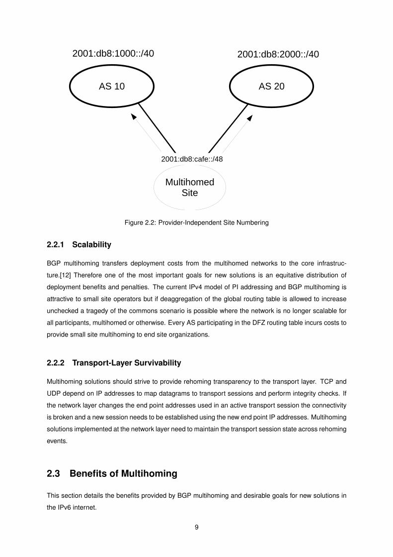
Figure 2.2: Provider-Independent Site Numbering
2.2.1 Scalability
BGP multihoming transfers deployment costs from the multihomed networks to the core infrastruc-
ture.[12] Therefore one of the most important goals for new solutions is an equitative distribution of
deployment benefits and penalties. The current IPv4 model of PI addressing and BGP multihoming is
attractive to small site operators but if deaggregation of the global routing table is allowed to increase
unchecked a tragedy of the commons scenario is possible where the network is no longer scalable for
all participants, multihomed or otherwise. Every AS participating in the DFZ routing table incurs costs to
provide small site multihoming to end site organizations.
2.2.2 Transport-Layer Survivability
Multihoming solutions should strive to provide rehoming transparency to the transport layer. TCP and
UDP depend on IP addresses to map datagrams to transport sessions and perform integrity checks. If
the network layer changes the end point addresses used in an active transport session the connectivity
is broken and a new session needs to be established using the new end point IP addresses. Multihoming
solutions implemented at the network layer need to maintain the transport session state across rehoming
events.
2.3 Benefits of Multihoming
This section details the benefits provided by BGP multihoming and desirable goals for new solutions in
the IPv6 internet.
9

2.3.1 Network Renumbering and Independence
Network operators seek PI addressing to avoid having to renumber their networks when changing ser-
vice providers. [13] In its current dual role IP addresses are also used for host identification purpose,
for example in software licensing terms, access control lists, inventory databases, etc. Manually renum-
bering all these databases imposes a very heavy cost that PI addressing avoids. It is therefore very
attractive for Operations, Administration and Maintenance (OAM) purposes to use PI addressing. RFC
1918 private addresses are a partial solution to the network renumbering problem while introducing a
whole host of new problems and breaking end to end connectivity due to the use of NAT.
2.3.2 Traffic Engineering
Traffic Engineering (TE) allows a site to make policy decisions over which link to the global network
should be preferred for certain classes of traffic. Outbound TE is generally easier because the site can
use an interior routing protocol to perform TE.[14]
For inbound TE the situation is more difficult. BGP has some provisions to allow a site operator
to steer inbound traffic between but these are not adequate enough to prove fine grained control for
inbound traffic.
Some sites resort to splitting an address allocation into smaller blocks and announcing each with
different properties. This practice again causes the global routing table to became deaggregated and
grow at supra-linear rates.
2.3.3 Redundancy
Redundancy is one of the main drivers for small site multihoming. Having two or more upstream
providers allows site to remain reachable if any one experiences problems. In such an event the site
connectivity should be able to switch to operational links. This transition should be seamless, that is,
preserver existing transport sessions, but that is not always the case. Particularly with NAT failover will
break live sessions.
2.3.4 Load Balancing
Networks may wish to use load balancing for inbound or outbound connections. Load balancing mech-
anisms distribute the current traffic load among the different upstream providers according to some
policy. This may allow for better performance and managing link congestion. This load balancing should
be concurrent and be independent of any cooperation with external networks.
2.4 Security Challenges
Introducing new mechanisms to allow transport sessions to change the topological IP address in use
introduces new threat scenarios. [15] The current IP architecture is already vulnerable to some source
10

address spoofing attacks. Any network node may generate network packets with invalid source ad-
dresses. These packets will be routed to their destination unless filtering mechanisms are in place to
drop invalid source addresses. This presents an attack vector in the present Internet. To mitigate this
risk Service Providers will implement ingress filtering from invalid source addresses.[16] Best current
practices for multihomed networks are specified in RFC 3704. [17]
A useful litmus test for multihoming proposals is whether the solution introduces additional vulnera-
bilities compared to the current Internet architecture.
Network attacks can be classed as on-path or off-path. On-path attacks require an attacker to have
access to all traffic exchanged between attacked nodes. Typically therefore control of core infrastructure
is required to pose an on-path attack. On-path attacks are therefore harder to mount and harder to
mitigate.
Off-path attacks do not require an attacker to see the datagram flow between source and destination
hosts. An example of an off-path attack would be a TCP SYN flood. TCP uses a three-way hand-
shake. The handshake establishes the shared state required to synchronize packet acknowledgements
and retransmissions. An attack that floods the target with SYN TCP packets that never complete the
handshake is a type of resource exhaustion attack.
2.4.1 Denial of Service
A denial of service attack will cause a network host to become unreachable. Multihoming solutions
require some kind of binding between a locator and a session identifier. Here session identifier is not
restricted to mean IP addresses. A session ID can be any shared state tokens that represent a datagram
flow between two endpoints. By manipulating this binding to use an invalid locator address an attacker
can create a denial of service attack where hosts become unreachable to one another.
2.4.2 Session Hijacking
If an attacker is able to alter the topological locator in use to one he controls he is able to perform
a session hijacking attack, where the victim is impersonated and its peer is unaware of this (without
further protections such as IPsec). This class of attacks is typically thwarted with an ephemeral session
cookie. Before allowing a locator change each peer must compare session cookies with enough entropy
to provide assurances that the new locator belongs to the same participants that originated the session.
This is an effective counter measure against off-path attacks. However cookies cannot provide protection
against on path attacks.
2.4.3 Flooding attacks
A flooding attack is one where a host is targeted with a high amount of unwanted and possible invalid
network traffic with the aim of causing resource exhaustion and link congestion. If an attacker is able to
change session locators to an address belonging to a third party, it is possible to coerce a multihomed
11

network node to send a flood of unwanted network traffic to the attacker’s target. If this traffic is, for
example, a multimedia video stream, such an attack can have a large amplification factor. Furthermore
to the flooded host the attack will appear to come from the multihomed host.
2.5 Map-n-Encap Using LISP
TCP/IP uses IP addresses as identifiers at the transport layer. There is a basic underlying assumption
that IP addresses identify a host. However IP addresses are a topological locator at the network layer.
Each IP address locates an interface as an attachment point to the network. Therefore transport ses-
sions happen between network interfaces rather than network hosts. The separation of the dual roles of
IP addresses in the current Internet architecture is termed Locator/Identifier split. This is generally seen
as an important architectural evolution that would allow more scalable and efficient networks but there
is no consensus on how to achieve this. [18]
Map-n-encap is the name for the general idea of using non-topological IP addresses as identifiers at
end sites and using a mapping system to map endpoint identifiers to globally routable locators. Currently
the most prominent solution using map-n-encap is LISP[19].
Figure 2.3: Map-n-Encap Edge/Core Separation
LISP[19] is a middle-box based multihoming mechanism. It aims to be an architectural solution
to the problem of locator/identifier separation. Furthermore one of the design goals of LISP is to be
deployable without requiring any modifications to hosts. It is currently being developed within the IETF
LISP working group. LISP is a dual stack network-layer based protocol that enables separation of the
dual role of IP addresses in the current Internet architecture by introducing two new numbering spaces:
Endpoint Identifiers (EIDs) and Routing Locators (RLOCs).
End sites are numbered using IP addresses as Endpoint Identifiers (EIDs). EIDs are site local and
therefore provide renumbering independence to network operators. Each EID is mapped to a Routing
Locator (RLOC) when egressing a site. This mapping is performed on site border routers designated as
12

Egress/Ingress Tunnel Routers (xTRs). After performing the mapping from destination EID to destination
RLOC the packet is encapsulated at the Egress Tunnel Router (ETR) and decapsulated at the Ingress
Tunnel Router (ITR). EIDs can be IPv4 or IPv6 addresses.
Figure 2.4: LISP Operation [Source: ”Deploying a Future Internet: the Locator/Identifier SeparationProtocol (LISP) case”][20]
The mapping system used to map EIDs to RLOCs is decoupled from the dataplane encapsula-
tion mechanism. Currently a LISP specific mapping system similar to the DNS called LISP Delegated
Database Tree (LISP-DDT) is being researched.
LISP sites cannot communicate with non-LISP sites. Some interoperability solutions are proposed
in RFC 6832 [21]. They depend on using Proxy ITRs announcing aggregated EID block to the global
routing tables and the use of NAT. This inter-operation solution adds a lot of complexity to the base
architecture.
2.6 Proposals for IPv6 Multihoming Solutions
Here we provide an overview of multihoming proposals currently active in the IETF besides LISP (ex-
plained in section 2.5).
13

2.6.1 IPv6-to-IPv6 Network Address Translation (NAT66)
IPv6-to-IPv6 Network Address Translation (NAT66) is the same loosely standardised NAT mechanism
used in IPv4. A NAT router performs address translation from a private addressing domain with non-
unique addresses to a public globally routable outward facing address. This is a model the IETF has
decided to abandon for IPV6 because it carries many disadvantages, the main one being the connectivity
is not end-to-end. To allow an internal host to be reachable the NAT router must keep a dynamic state
table mapping the address-port tuple outside to inside address. This mapping typically has a timeout on
the order of a minute, after which the connection is likely to break. Inbound connection establishment
is not supported without manual configuration or unreliable workarounds. The advantages of NAT66
are easy deployment for non-server hosts and some support for load balancing and failover to multiple
service provides. However its many drawbacks provide an incentive to research better multihoming
mechanisms to prevent market forces to propel the middle-box difficulties facing the Internet today.
2.6.2 IPv6-to-IPv6 Network Prefix Translation (NPTv6)
IPv6-to-IPv6 IPv6 Network Prefix Translation (NPTv6) [22] is a NAT mechanism for IPv6 that overcomes
some of the limitations of IPv4 NAPT while providing some of the goals of multihoming solutions. NPTv6
performs stateless algorithmic translation between site local prefixes and globally routable prefixes. This
translation is performed without requiring any per-flow state to be maintained in the address translation
network elements. Furthermore NPTv6 allows 1:1 mapping of outer addresses to inner addresses.
This situation is an improvement over NAT that depends on port mappings to allow internal hosts to be
reached and can generally only support TCP or UDP traffic.
NPTv6 provides address independence. Local hosts are numbered using an internal prefix that is
provider independent. No network renumbering is required when changing service providers. However
in a multihoming scenario NPTv6 cannot provide transparent failover between redundant links. If each
NPTv6 translator attaches to different globally routable external prefixes in a failover event an external
host to the site will see a locator change and the transport session is broken. Another limitation of
NPTv6 is that any IP addresses exchanged in the upper layers will not be globally routable, requiring the
use of NAT traversal mechanisms such as STUN. In particular IPsec cannot work between hosts behind
NPTv6 boxes without the use of NAT traversal solutions.
2.6.3 Level 3 Multihoming Shim Protocol for IPv6 (Shim6)
Level 3 Multihoming Shim Protocol for IPv6 (Shim6)[23] is a multihoming protocol under IETF standards
track category. Shim6 gained rough consensus following the MULTI6 working group effort but no test
deployments have happened so far.
Shim6 is a host based solution using multiple globally routable prefixes. The goal for Shim6 is to
allow a session to change locators seamlessly. Each host has several IPv6 routable addresses and
one is selected for connection establishment using the normal connection methods. This address is
designated as an Upper Layer Identifier (ULID). Therefore no new namespace is required. Each host
14

will then perform locator exploration and store the peer locator points. When to do the locator exchange
is implementation defined according to some heuristic. This state defines a session context. The Shim6
protocol defines the protocol messages for hosts to establish this state using a four-way handshake.
If a locator failure is detected using a suitable mechanism (Shim6 also includes a path exploration
and reachability protocol [24]) then a new working locator pair is selected from the shared context. At
this point an IPv6 extension header is introduced into the dataplane packets carrying a 47 bit context tag.
When the IP stack receives such a packet it will replace the current locator with the stored original ULID
so the transport layer’s view of the connection endpoints remains the same. This mechanism therefore
allows locator agility in case of path failures or other renumbering events while preserving transport
sessions.
The operational requirements and implications of Shim6 are at this point unknown.
2.6.4 Host Identity Protocol (HIP)
The Host Identity Protocol (HIP)[25] is based on a new namespace of host identifiers using the public key
of an asymmetric key-pair. Public keys are not exchanged in the protocol itself. Instead a 128 bit hash
of the public key, called Host Identity Tags (HITs), is used. HIP also introduces a base cryptographic
exchange to assert ownership of the HIT base on public key cryptography. Because the Upper Layer
Protocol (ULP) binds to the HIT instead of a topological locator, transport session mobility is achieved.
The main goal of HIP is to introduce a new identifier name space and decouple the IPv6 address from
that role.
The HIP payload uses IPsec Encapsulating Security Protocol (ESP) for the actual exchange of data.
In practice the Host Identity is only used in the base exchange. Given an IPsec transport association
the IPsec Security Parameter Index (SPI) is used as a session identifier that maps to the Host Identity.
Because HITs are constructed using a hash function they do not have a natural hierarchical structure.
Therefore global resolvability of HITs to topological addresses is difficult to realize. The DNS is based
on a recursive tree architecture and depends on this property of IP addresses to resolve names to
addresses. To have a global name resolution mechanism for HITs a new mechanism is required. The
Distributed Hash Table has some promise here but until such a mechanism is available HIP seems of
limited applicability in the current Internet.
2.6.5 Identifier-Locator Network Protocol (ILNP)
Identifier-Locator Network Protocol (ILNP)[26] is another solution focused on clear separation of iden-
tifier and locator namespaces. ILNP follows an alternative approach taking advantage of the extended
address space for IPV6. Each IPv6 address is split into two components, an identifier and locator, by
redefining the semantics of the IPv6 interface 64 bits identifier to be a node identifier. This identifier only
has significance inside the local ILNP domain and must remain constant for the session duration.
Because ILNP changes the semantics of IPv6 addresses it requires changes to the host network
stack to bind the transport session only to the 64 bit node identifier instead of the traditional 128 bit IPv6
15
address. The ILNP addressing model does not provide for site renumbering independence, i.e, network
numbering (considered as a tuple of 64 bit locator and identifier) is dependent on the topological AS
prefix. Some changes to the DNS are also required to support well ILNP as a mapping system.
2.6.6 Transport Layer Solutions
Instead of implementing multihoming at layer 3 of the Internet protocol stack it is possible to do multi-
homing in the transport layer. In TCP/IP the separation between Network and Transport layers is not
strictly enforced. A TCP session binds directly to a topological IP address. TCP also uses an IP pseudo
header to perform checksum computations that includes source and destination IP address (both for
IPv4 and IPv6).
Multipath-TCP (MPTCP)[27] is an extension to existing TCP interfaces to allow TCP to use multiple
subflows. MPTCP extensions add authentication and locator exchange logic to standard TCP. This
extra signaling introduces a lot of additional complexity to the traditional mechanisms of TCP. During the
traditional three-way TCP handshake a host will signal support for MPTCP using TCP options. If both
endpoints agree on using multipath extension to TCP then session authentication keys are exchanged.
From that point on MPTCP capable hosts can add or remove subflows to existing TCP sessions.
SCTP[28] is a new transport protocol developed by the SIGTRAN working group to carry Public
Switched Telephone Network (PSTN) signaling over IP. However SCTP is a generic transport protocol
proporting to provide many improvements over standard TCP/IP. SCTP is a multi-stream protocol similar
to MPTCP in that regard. Each SCTP connection can carry multiple parallel streams of independent data
between endpoints. SCTP was also designed from the ground up to support multihoming to increase
connection reliability and includes signaling to exchange locator sets between peers. SCTP includes
a path management module that monitors path failures and link performance. If the path is deemed
to be failed or underperforming the protocol includes message primitives to move the SCTP transport
association to a different pair of locator addresses.
Implementing multihoming at layer 4 is arguably easier because some state is inherently required
to manage locators and transport protocols already maintain state, such as acknowledgements, that
is useful to manage locators. Furthermore a layer 4 protocol can implement a transient Session ID
to synchronize state between endpoints. The obvious advantage of implementing multihoming in the
network layer is that all upper layer protocols can automatically benefit from session survivability for
multiple IP address use. Network layer extensions may also be easier to deploy, given the early stages
of IPv6 deployment, and lessen or eliminate the impact on existing applications.
2.7 Summary of Multihoming Solutions
So far there is no clear choice within the IETF on namespace separation and IPv6 multihoming solutions.
Host based multiple prefix solutions studied in the IETF have not yet seen live deployments. The problem
of source address selection and lack of provider independence are drawbacks of such proposals.
16

NPTv6 can provide renumbering independence but cannot support referrals. Any protocol embed-
ding IP addresses will break. Such addresses are private and non routable therefore cannot be used in
application payloads without NAT traversal mechanisms. Of particular significance is that NPTv6 does
not support IPsec.
LISP has seen active research and development, supported by both industry and academic efforts.
Some aspects of LISP deployment are not yet fully clarified. The security of the LISP mapping system is
under active research. Currently the mapping system used, LISP-DDT, uses pre-shared keys for security
map registration. The use of pre-shared keys cannot scale to the size of the Internet. LISP is a middle-
box solution and therefore does not respect the end-to-end principle. The compatibility mechanism
proposed between the LISP and non-LISP core requires using proxy mechanisms and NAT methods
that raise many operational and architectural concerns.
2.8 Discussion
The architecture proposed in this thesis is based on the Locator-Identifier separation concept. How-
ever we choose to replace the map-n-encap method of locator identifier separation with a map-n-route
method. Mapping of locator to identifiers is performed by hosts instead of middle-boxes. In this archi-
tecture, which we call MH6R for convenience, site border routers do not have to keep any state. This
provides transparency and backward compatibility at the cost of requiring changes to the host network
layer. This is an efficient way to provide IP address independence and an end-to-end oriented solution
to challenges faced by multihoming solutions.
17

18

Chapter 3
Data Plane Architecture
In this chapter we propose a novel data plane architecture for providing small site multihoming using
host based locator identifier separation. The use of native IPv6 mechanisms is favored to preserve end
to end transparency and lower deployment costs.
The first section of this chapter presents a review of relevant IPv6 specifications. After that the data
plane architecture is introduced and an example of packet forwarding provided. Finally the impact on
current network operation is analyzed.
3.1 Globally Routable IPv6 Addresses
In an IPv6 network each host is assigned a 128 bit address. From the point of view of the transport layer
and above the address is simply an opaque bit string. At the network level there is more structure to the
address.[29]
Each address follows a three level hierarchical structure (figure 3.1). Global routing is performed
using a routing prefix of the first n bits (the bit mask).
Subnetting is used to partition the address space into different local routing domains. The subnet
bits are only used for local routing inside a local subnetwork.
The Interface ID is used to identify interfaces on a link. In the case of shared-medium link-layer
technologies such as Ethernet the Interface ID is used to resolve an IP layer address to a link layer
address using Neighbour Discovery. The Interface ID is defined in RFC 4291 to be 64 bits long for
global unicast addresses whose prefix does not begin with 000.[29]
IPv6 also introduced the concept of scopes to the addressing architecture. [30] An IPv6 address
originally could have three different unicast scopes: link-local, site or global. Site scope addressing was
deprecated in RFC 3879 [31] because it was considered to be poorly defined for address selection rules.
n bits m bits 128-n-m bits
Global Routing Prefix Subnet ID Interface ID
Figure 3.1: IPv6 Global Unicast Addresses
19
3.2 Unique Local IPv6 Unicast Addresses
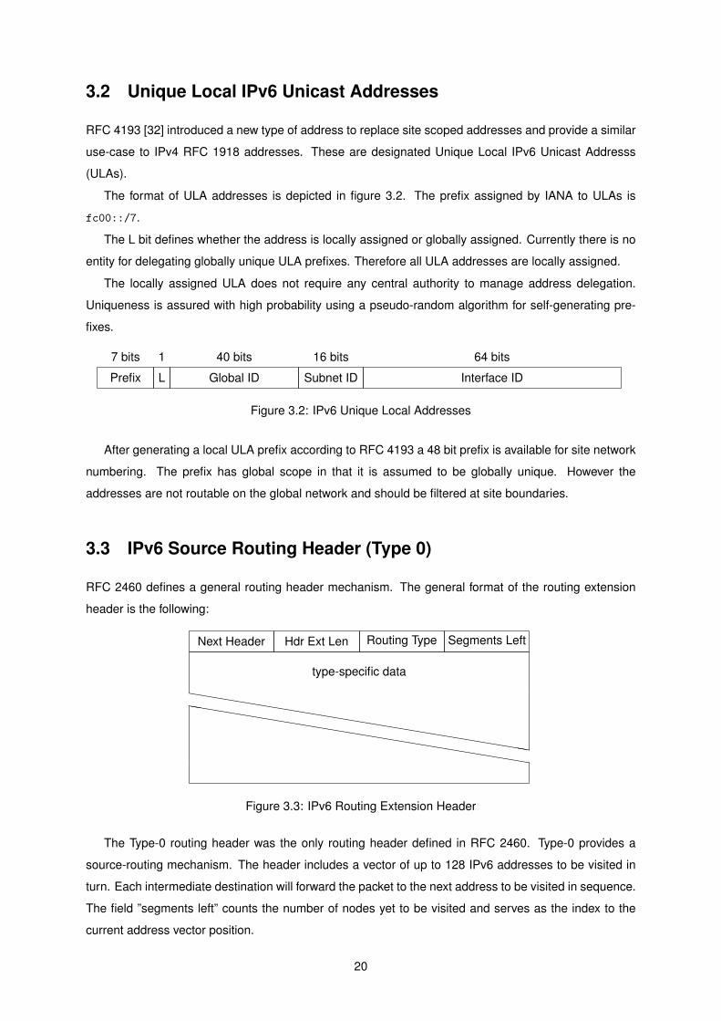
RFC 4193 [32] introduced a new type of address to replace site scoped addresses and provide a similar
use-case to IPv4 RFC 1918 addresses. These are designated Unique Local IPv6 Unicast Addresss
(ULAs).
The format of ULA addresses is depicted in figure 3.2. The prefix assigned by IANA to ULAs is
fc00::/7.
The L bit defines whether the address is locally assigned or globally assigned. Currently there is no
entity for delegating globally unique ULA prefixes. Therefore all ULA addresses are locally assigned.
The locally assigned ULA does not require any central authority to manage address delegation.
Uniqueness is assured with high probability using a pseudo-random algorithm for self-generating pre-
fixes.
7 bits 1 40 bits 16 bits 64 bits
Prefix L Global ID Subnet ID Interface ID
Figure 3.2: IPv6 Unique Local Addresses
After generating a local ULA prefix according to RFC 4193 a 48 bit prefix is available for site network
numbering. The prefix has global scope in that it is assumed to be globally unique. However the
addresses are not routable on the global network and should be filtered at site boundaries.
3.3 IPv6 Source Routing Header (Type 0)
RFC 2460 defines a general routing header mechanism. The general format of the routing extension
header is the following:
Next Header Hdr Ext Len Routing Type Segments Left
type-specific data
hhhhhhhhhhhhhhhhhhhhhhhhhhhhhhhhhhhhhhhhhhhhhhhhhhhhhhhhhh
Figure 3.3: IPv6 Routing Extension Header
The Type-0 routing header was the only routing header defined in RFC 2460. Type-0 provides a
source-routing mechanism. The header includes a vector of up to 128 IPv6 addresses to be visited in
turn. Each intermediate destination will forward the packet to the next address to be visited in sequence.
The field ”segments left” counts the number of nodes yet to be visited and serves as the index to the
current address vector position.
20

Type-0 routing headers have been deprecated because they introduced some increased security
risks associated with source routing [33]. If a routing header includes repeating addresses it is possible
to mount a resource exhaustion attack with amplification. A malicious source routed packet can be
routed to bounce repeatedly over the same link. The risk was deemed serious enough to deprecate
the Type-0 routing header entirely although other more limited uses of the generic routing header are
possible. One such example is the Mobile IPv6 Type-2 routing header [34].
Next Header Hdr Ext Len 0 Segments Left
Reserved
Address[1]
Address[2]
...
Address[n]
Figure 3.4: IPv6 Type-0 Routing Header
Support for Type 0 routing header was mandatory for a fully compliant IPv6 implementation until
being deprecated. RFC 2460 specifies the following algorithm for the Type 0 header:
21

if Segments Left = 0 {proceed to process the next header in the packet, whose type isidentified by the Next Header field in the Routing header
}else if Hdr Ext Len is odd {
send an ICMP Parameter Problem, Code 0, message to the SourceAddress, pointing to the Hdr Ext Len field, and discard thepacket
}else {compute n, the number of addresses in the Routing header, bydividing Hdr Ext Len by 2
if Segments Left is greater than n {send an ICMP Parameter Problem, Code 0, message to the SourceAddress, pointing to the Segments Left field, and discard thepacket
}else {
decrement Segments Left by 1;compute i, the index of the next address to be visited inthe address vector, by subtracting Segments Left from n
if Address [i] or the IPv6 Destination Address is multicast {discard the packet
}else {
swap the IPv6 Destination Address and Address[i]
if the IPv6 Hop Limit is less than or equal to 1 {send an ICMP Time Exceeded -- Hop Limit Exceeded inTransit message to the Source Address and discard thepacket
}else {
decrement the Hop Limit by 1
resubmit the packet to the IPv6 module for transmissionto the new destination
}}
}}
Figure 3.5: IPv6 Source Routing Header Algorithm
3.4 Thesis Proposal
The network architecture described in this section follows some of the same ideas as a map-n-encap
multihoming solution (such as LISP). Each network site is numbered using site-local addressing. The
IPv6 address format used for site local addressing is assumed to follow the format of the IPv6 ULA. We
will use the designation of Site Local Address (SLA) for globally unique, non-globally routable addresses
used for end site numbering.
Connectivity from the site to the global Internet is provided by one or more Site Border Routers
(SBRs). Each SBR interface connected to an upstream provider is numbered using provider-aggregable
globally routable addressing. We will use the designation Globally Routable Address (GRA) for the usual
type of IPv6 address described in section 3.1.
To connect to a peer a host will establish a mapping from the peer’s SLA to the GRA assigned to the
site SBR. The peer SLA is obtained by the usual methods, such as DNS name resolution of a host name
22

Figure 3.6: Map-n-Route Edge/Core Separation
Figure 3.7: Network Architecture
to an SLA address using AAAA resource records. The mapping of SLA to GRA is done using a suitable
mapping system. DNS is also a good candidate here, with its proven record of massive distributed
scalability. The details of using the DNS to map SLAs to GRAs are developed in chapter 4.
It should be noted that the use of site local addresses solves the IPv6 multihoming and renumbering
problems but the SLA has a limited role as an upper layer identifier. There are no new namespaces at
the transport layer. Intra-site IP connectivity remains unchanged. Therefore the SLA is an identifier in
the somewhat limited sense of non-topological addressing.
Figure 3.8 represents a datagram flow between Host-A and Host-B. Host-A requires the following
data primitives to reach Host-B:
• Source host SLA
• Local SBR Address (explained below)
• Destination SBR GRA
• Destination Host SLA
23

Figure 3.8: Network Routing
Packet routing proceeds in three stages or segments. First segment destination address is SBR-A1.
Second segment destination address is SBR-B2. This segment destination address is Host-B SLA. In
each segment the source address used is the address associated with the egress interface. This is
different from Type-0 routing, where the IP header source address remains static.
When selecting an SBR, Host-A can use the SBR’s inner SLA or outer GRA. Using the GRA is useful
when using Authentication Header (AH) to protect the integrity of the packet but imposes two additional
constrains: there must be routing inside the local network to the SBR GRA; and Host-A must know the
set of SBR GRAs.
We will assume here the simpler case where segment Host-A to SBR-A1 uses SLA addresses (fig-
ure 3.9).
3.5 Packet Flow Sequence
This section details the packet flow sequence when Host-A wishes to initiate a transport session to Host-
B. We assume Host-B has DNS AAAA record for hostname server.example.com pointing to fdbb::2.
Briefly the steps are:
1. Resolve server.example.com to an SLA (for example an IPv6 ULA).
2. Given an IPv6 SLA for Host-B (fdbb::2), resolve that to a set of AAAA records (GRA) for the site
SBRs (IPv6 unicast globally routable address).
3. Select a remote SBR from the set of AAAA records corresponding to fdbb::2 and construct a
routing header (Destination GRA, Destination SLA).
4. Choose a local SBR and forward the packet with a local SLA source address and destination local
SBR.
5. When the local SBR receives the packet addressed to itself and follows the header chain it will
perform the multihoming routing header algorithm and forward the packet to the remote SBR with
its GRA as source address.
24

6. When the remote SBR receives the packet it will perform the same routing algorithm and forward
the packet to Host-B SLA with its SLA as source address.
7. Host-B receives the packet from the site SBR with a multihoming routing header containing the
peer’s SLA and GRA addresses.
The name resolution mechanism to map identifiers to locators is further explained in chapter 4. The
dataplane forwarding mechanism is depicted in figure 3.9.
Figure 3.9: End-to-End Multihoming Connection Segments
Here the host obtains an identifier represented as a non-routable IPv6 address by the usual name
resolution methods (possibly static configuration). This non-routable destinion identifier, called an SLA
in this work, needs to be mapped to the globally routable IPv6 address of the SBRs connecting the des-
tination site. In the case of multihoming one SLA will map to two or more destination GRAs belonging to
the destination site SBRs. The map server used to perform this lookup is independent of the forwarding
plane. Here we consider how the DNS can be used in this role. This has the advantage that the DNS is
extensible and widely deployed with a proven track record of reliability and scalability.
The top two boxes in figure 3.9 represent a conceptual view of the host stack for a single datagram
upon sending and receiving respectively. Below are the actual datagrams transmitted on the wire, in
each of the three distinct connection segments. It is important to note here that the role of both SBRs
is completely stateless. An SBR receiving a datagram will invoke its multihoming header module on
the respective packet header, apply some sanity checks, perform the multihoming routing algorithm
(explained in section 3.6) and forward the packet using the normal IP dataplane. None of these steps
fall outside the usual scope of an IPv6 router. Only a new type of RFC2460 compliant routing header
must be supported. This lowers the barriers to deployment because upgrading network infrastructure is
generally costly.
25

3.6 Multihoming Routing Header
This section presents the concrete protocol and algorithmic details of the routing header described
conceptually in the previous chapters.
The multihoming header used in this work follows the format of the IPv6 RFC2460 routing header
described in 3.2. In the case of SLA to SLA packet flow the number of addresses is always two so the
header extension length is 4.
Next Header Hdr Ext Len Type = X Segments Left
Reserved
Address[1]
Address[2]
Figure 3.10: IPv6 Multihoming Extension Header
A receiving node executes the following algorithm when receiving a Multihoming Header:
26

if Segments Left = 0 {proceed to process the next header in the packet, whose type isidentified by the Next Header field in the Routing header
}else if Hdr Ext Len is odd {
send an ICMP Parameter Problem, Code 0, message to the SourceAddress, pointing to the Hdr Ext Len field, and discard thepacket
}else {
compute n, the number of addresses in the Routing header, bydividing Hdr Ext Len by 2
if n is greater than 2 {send an ICMP Parameter Problem, Code 0, message to the SourceAddress, pointing to Hdr Ext Len, and discard thepacket
}else if Segments Left is greater than n + 1 {
send an ICMP Parameter Problem, Code 0, message to the SourceAddress, pointing to the Segments Left field, and discard thepacket
}else {
decrement Segments Left by 1;
if Segments Left = 0 {swap Address[1] and IPv6 Source Addressresubmit the packet to the IPv6 module for transmissionto the new destination
}else {
compute i, the index of the next address to be visited inthe address vector, by subtracting Segments Left from n + 1
if Address [i] or the IPv6 Destination Address is multicast {discard the packet
}else {
copy Address[i] to IPv6 Destination Addresscopy IPv6 Source Address to Address[i]
if the IPv6 Hop Limit is less than or equal to 1 {send an ICMP Time Exceeded -- Hop Limit Exceeded inTransit message to Address[i] and discard thepacket
}else {
decrement the Hop Limit by 1
resubmit the packet to the IPv6 module for transmissionto the new destination
}}
}}
}
Because the Multihoming Header has a maximum length of two addresses and furthermore the
addresses have different properties (as encoded in the prefix) the Type-0 security threat is not applicable
to multihoming.
RFC 2460 defines the how a node should handle an unknown routing header type as follows:
27

If, while processing a received packet, a node encounters a Routingheader with an unrecognized Routing Type value, the required behaviorof the node depends on the value of the Segments Left field, asfollows:
If Segments Left is zero, the node must ignore the Routing headerand proceed to process the next header in the packet, whose typeis identified by the Next Header field in the Routing header.
If Segments Left is non-zero, the node must discard the packet andsend an ICMP Parameter Problem, Code 0, message to the packet’sSource Address, pointing to the unrecognized Routing Type.
If a receiving node does not support the Multihoming Header it cannot ignore a routing header with
segments left equal to zero. If it did it would see an incorrect IPv6 source address. Receiving terminal
nodes must swap the IPv6 source address with the first address in the multihoming header address
vector. Therefore the terminal node will always receive a multihoming header with segments left equal
to 1. If the routing header type is not supported the node replies with an ICMPv6 parameter problem
error message and the connection establishment can fallback on alternative methods such as one-to-
one IPv6 connectivity.
The packet overhead of MH6R is the same as the overhead for any other IPv6 routing header. In
the general case this is 8 + n x 16 bytes for n addresses. This thesis studies the case of small site
multihoming. When each site is using local addressing the size of the routing header is 40 bytes for n =
2. The ”Type” field used in testing was 253 (experimental).
Although classed as an IPv6 extension header, the Multihoming Header shares implementation sim-
ilarities with IPsec architecture headers such as AH.
3.7 Handling ICMPv6 Errors
Internet Control Message Protocol version 6 (ICMPv6) is used in the Internet Protocol as control and
signalling protocol. ICMPv6 messages are classed as error messages or informational messages. Error
messages are directed at the originating node to signal connectivity failures without relying on time-
outs. They can be generated by any intermediate node on the path. The destination address for an
ICMPv6 error message is the source address of the packet originating the error condition. The packet
structure [35] is depicted in figure 3.11.
Any error conditions occurring in the path segment between SBRs (the global network) will be ad-
dressed to the originating SBR. This requires the SBR to extract the encapsulated multihoming header
inside the ICMPv6 payload and forward the error message to the source SLA (figure 3.12).
28

Type Code Checksum
Type Specific Field
As much of invoking packer as possible without the ICMPv6packet exceeding the minimum IPv6 MTU
hhhhhhhhhhhhhhhhhhhhhhhhhhhhhhhhhhhhhhhhhhhhhhhhhhhhhhhhhh
Figure 3.11: ICMPv6 Error Message
Figure 3.12: ICMPv6 Error Forwarding
3.8 Backward Compatibility
The use of SLAs for global connectivity in MH6R does not preclude the use of globally routable ad-
dresses inside the local network. These are particularly useful combined with existing automatic ad-
dress configuration procedures. When resolving an Fully Qualified Domain Name (FQDN) to a set of IP
addresses a host may receive an SLA and global IPv6 addresses. Which one is preferred is a matter
of local policy. If resolving the SLA to another set of locators fails or any other path failures arise it is
possible to fallback on using conventional IPv6 connectivity.
29

A host may continue to use globally routable IPv6 addresses alongside the site local address. In
case a name resolution lookup does not provide a remote site local address to attempt a mapping, the
host can fallback on using current IPv6 connection mechanisms to communicate. Therefore backward
compatibility is assured without any dedicated mechanism.
3.9 Inter-operation Between IPv6 and IPv4 Networks
GRA addresses belonging to an SBR can take the form of an IPv4-mapped IPv6 address. In the case
where an IPv6 end-site has IPv4-only uplinks to the Internet, address family translation is performed in
the inter-site segment. This allows inter-operation of IPv6-only sites across an IPv4 core (figure 3.13).
One problem with IPv4 inter-site transit is that ICMPv4 error packets only contain the original IPv4
header plus 8 bytes. This assumes the first 8 bytes carry the source and destination ports for the flow.
When using MH6R an SBR will not have access to the encapsulated routing header to forward the
ICMPv6 packet to the site-local ULA. A possible workaround would be to use UDP encapsulation and
keep a stateful mapping of source ports to MH6R flows but details are left for further study.
Figure 3.13: IPv6-IPv4 Inter-operability
3.10 Host Requirements
Using MH6R does not require changes to application code. For a native IP stack implementation only
changes to the kernel IP implementation are required. This presents a low-cost path to deployment
given strong enough incentives for technological deployment. Some policy routing extensions to route
30
traffic to selected gateways are beneficial.
Using the BSD socket API an application will bind the socket to an SLA obtained by resolving the
FQDN in the DNS. The network layer is responsible for resolving the address to a set of globally routable
locators to obtain the tuple (source ULA, source GRA, destination GRA, destination ULA).
Two data structures are helpful for implementation purposes. One map cache to store resolved
SLA-GRA mappings and a flow table with the current active locators per flow.
3.11 Router Requirements
MH6R requires minimal changes to SBRs interconnecting private and global routing realms. There is
no local state required from SBRs. A new IPv6 routing header type must be supported in SBRs. The
multihoming routing header follows the format of the general IPv6 routing extension header therefore
implementation effort is expected to be minimal. The algorithm to process the MH6R header is similar
to the Type-0 routing header algorithm. The one different is that the ingress source IPv6 address is re-
placed with the router’s interface address on egress, effectively performing address translation between
local addresses and global addresses.
To implement security policies and packet filtering the implementation must take into account the
translation performed between SLAs and GRAs.
ICMPv6 packets received by SBRs must be forwarded by inspecting the encapsulated MH6R header.
The source address on the IPv6 header encapsulating ICMPv6 is kept unchanged to point to the error
source. This is reasonable because ICMPv6 error packets cannot generate other ICMPv6 errors.
31

32

Chapter 4
DNS as a Loc/ID Mapping System
In this chapter we describe how DNS can be used as a Loc/ID mapping system within MH6R. The use
of DNS is a natural choice as a scalable distributed database. Here we demonstrate the use of DNS as
a proof of concept mapping system. However the mapping system is decoupled from the dataplane and
other systems could be used.
4.1 Introduction to DNS Name Lookups
The DNS is a globally distributed hierarchical database used to map names to objects using resource
records. The network stack only uses IP addresses to route packets but IP addresses are cumbersome
for people to use. For this reason the DNS was introduced to give human readable names to network
hosts.
A DNS name is a hierarchical set of subdomain names from the DNS root to the host name. The DNS
root is represented by a single dot and usually omitted. For example the name server.tecnico.ulisboa.pt
is a Fully Qualified Domain Name (FQDN). An FQDN completely specifies its location in the DNS hier-
archy. To resolve this name to a set of IPv6 addresses a type of resource record called AAAA is used.
Each AAAA response contains one or more IPv6 addresses belonging to the name being queried.
To perform DNS name resolution a host will use a stub resolver. A stub resolver is used to send
a DNS query to a Recursive DNS Server (RDNSS). The RDNSS is responsible for following the name
hierarchy until it finds an authoritative server responsible for the queried name (or else a ”name not
found” error is returned). To resolve the name server.tecnico.ulisboa.pt the RDNSS will first query
the root for the pt authoritative server. Then it will query that DNS server for an authoritative server
for the ulisboa.pt subdomain. This process is recursively repeated until an authoritative DNS server
provides an AAAA resource record for the host server belonging to the tecnico.ulisboa.pt domain.
The DNS also supports mapping from IP addresses to host names. This is called a reverse IP
lookup. To resolve an IP address to a host name the PTR resource record is used. To resolve the IP
address 2001:db8:beef:cafe::1 the address is transformed into a DNS name by splitting into nibbles
and reversing the address. Therefore the address 2001:db8:beef:cafe::1 would correspond to the
33

DNS name:
1.0.0.0.0.0.0.0.0.0.0.0.0.0.0.0.e.f.a.c.f.e.e.b.8.b.d.0.1.0.0.2.ip6.arpa.
The ip6.arpa domain is the DNS hierarchy root for reverse IP lookups.
4.2 SLA to GRA Mapping Using the DNS
The use of site local addressing requires a mapping system to resolve SLAs to a globally routable
address for the site’s SBRs. Here we will consider the DNS as a mapping service for SLA to GRA
resolution. Each site local address is assumed to follow the format of an ULA [36].
To map a ULA to a GRA we need only map the Global ID to a set of SBR IPv6 GRA addresses. The
forward lookup process is depicted in figure 4.1
Figure 4.1: Forward Identifier Resolution
The use of the 48 bit Global ID is sufficient to map any ULA belonging to the local site to its SBR lo-
cator set. Taking advantage of local caching of DNS queries this requires fewer lookups than performing
ULA to GRA lookups of the full ULA DNS name. For that reason it is assumed that Global Site IDs are
delegated on the ulac.arpa DNS root (ulac standing for ULA-Central. [37]).
4.3 Traffic Engineering
Traffic engineering refers to the ability to a site to manage the usage of multiple links to reach the DFZ.
A common situation for a multihomed site is having unbalanced traffic loads with one link congested and
others underutilized.
Outbound traffic engineering is well supported with the MH6R dataplane. All the policy routing mech-
anisms can be used to selected an SBR for egressing traffic. Because the data plane is segmented and
34

Figure 4.2: Off Path Attack With Forged Headers
the first segment has an explicit SBR has destination address, load balancing is easily achieved. To pre-
vent asymmetric routing, responder nodes should return traffic using the same path as inbound traffic.
Inbound traffic engineering is not supported without extending the DNS resource records. The map-
ping system must support some form of priority and load balancing preference. Currently no such fields
exist for AAAA records. Other types of DNS resource records, such as MX records used for email,
support a preference number to direct inbound SMTP sessions. Such a mechanism is lacking when
resolving site local addresses to routing locators using AAAA records.
Presumably this is one of the reasons why LISP uses its own mapping system, similar to the DNS
hierarchy. LISP map records support priority and weight fields to perform inbound traffic engineering for
RLOCs.
4.4 Securing Locator Identifier Bindings
The separation of locator and identifier introduces new threat models not present on the Internet today.
If the mapping between locator and identifier is not authenticated the network is vulnerable to off-path
attacks (figure 4.2). An attacker can simply forge a routing header pointing to a globally routable address
owned by the attacker.
DNS with DNSSEC extensions provides a trusted mapping between local address and global ad-
dress. To verify the legitimacy of a binding inserted in a routing header a host can perform a DNS
lookup and validate whether the include GRA belongs to the site locator set. DNSSEC extensions
provide authentication and integrity to DNS lookups (but not confidentiality).
However reverse lookups introduce latency in the session establishment. Furthermore if a host per-
35

forms a reverse lookup for every ULA not in its map cache this poses a potential vector to mount DNS
denial of service attack and resource exhaustion attacks. With DNSSEC extensions this risk is exac-
erbated because cryptographic computations incur additional cost. This poses a resource exhaustion
problem on the receiving host and on the DNS system. Reverse DNS lookups are too costly to perform
without some trust in the remote peer.
For a receiving host the solution proposed is to delay the reverse lookup according to a heuristic
measure of the transport session. Until then the locator is considered untrusted and no session re-
silience is afforded to the connection. The connection can still be established between hosts but locator
mobility cannot be performed in a secure manner until the receiving host has a trusted binding for the
initiating peer’s set of locators.
4.5 Discussion
The use of DNS for locator identifier mapping requires further experimentation. Because only Global
IDs need to be mapped with MH6R, the requirements are considered to be low cost.
The implementation of the mapping system should support multiple different systems. It is expected
that the data plane would be implemented in kernelspace and an API similar to PF KEY [38] would allow
the kernel to pass mapping requests to userspace.
36

Chapter 5
Testing and Results
5.1 Methodology
The methodology adopted is functional in nature with the purpose of validating the correctness of the
routing header algorithm and whether it conforms to the end-to-end principle of IP. This testing proved
useful in guiding some design decisions that might not have been obvious otherwise.
The splitting of forwarding plane into three distinct path segments requires considering the impact on
aspects such as MTU handling and ICMPv6 error conditions.
5.2 Implementation
To test the routing header mechanism a prototype was developed in C. The implementation currently
covers only the IPv6 data plane with multihoming routing headers. It consists of two userspace pro-
cesses using the TUN/TAP driver available in Unix-like systems. TUN/TAP allows a userspace process
to receive packets directly from the kernel, functioning as a next hop from the kernel’s point of view. This
is essentially a bump in the wire implementation for network protocols.
5.2.1 Network Host Process
The host runs a userspace process as a system daemon. The daemon will open two file descriptors: one
for the TUN/TAP driver to receive egress packets from the upper layer and a UDP socket file descriptor
to receive packets from the network layer. UDP encapsulation is not required but it use greatly facilitates
network programming in userspace.
When egressing from the kernel’s routing system the packet is sent to the daemon on the TUN/TAP
file descriptor. The daemon is responsible for mapping the remote SLA to a remote GRA and inserting
the corresponding extension header into the packet.
When a packet is ingressing it is received on the UDP network socket. In that case the daemon will
remove the extension header and send the packet on the TUN/TAP interface. The kernel will see an
37

inbound packet on the virtual interface. The source and destination addresses are the host and peer’s
SLA. When the kernel receives the packet it follows the normal processing and is then handed over to
the upper layer.
Given a new egress flow the daemon must map the remote SLA to a remote GRA belonging to
an SBR for that network site. All map lookups are performed using a static configuration file. This
configuration file allows using multiple SBR addresses per site. It is also possible to assign priority and
weight values to a locator. This provides traffic engineering for the multihoming solution. If a name
resolution system is being used, such as the DNS, it needs to provide such a capability to allow for
traffic engineering.
5.2.2 Site Border Router Process
Each SBR runs a daemon process in userspace to process multihoming routing headers. The daemon
listens on a single UDP socket on a well know port number.
The process listens on both site facing and global network facing interfaces. Upon receiving a packet
with multihoming header it will perform the header processing algorithm on the packet and forward it on
the proper interface.
5.2.3 Control Plane
The control plane is statically configured in this prototype implementation. Two text plain text files are
used. The mapping from Global Site ID to GRA is configure in a hosts file, whose format is the following:
map {
gid = fdbb::
ip6 = {2001:db8:1::1, 2001:db8:2::1}
}
Each map directive maps one GID to one or more GRAs. Each IPv6 address corresponds to the
remote site SBR.
IPsec AH is configured using preshared keying. The format is the following:
sad {
ula = fdbb::1
key = 0x11223344551111111111111111111111111111AA
}
The IPsec secret key is configure per host. Each sad directive defines an IPsec Security Association
Database (SAD) association with a shared 160 bit secret key. This key must be statically configured on
both endpoints. The IPsec AH algorithm implemented is HMAC-SHA1-96.
38

5.3 Testbed
The test scenario is implemented using Linux Containers (LXC). The Linux distribution used is Arch
Linux using Linux kernel 4.1. Each network element is virtualized inside an LXC container with a full root
filesystem. Figure 5.1 describes the network topology.
Figure 5.1: Testbed Topology
There is no direct routing between Host-A and Host-B. The network is segmented into three distinct
routing realms. Host-A only has routes to R11 and R12 and vice-versa for Host-B. Traffic from Host-A
to fdaa::/48 egresses through switch S1. The default route points to the TUN interface of the MH6R
daemon.
The network 2001:db8::/32 represents the DFZ. The routers are connected through switch S2. Only
SBRs have routes to the respective end sites. For example there is no direct routing from R11 to Host-B.
5.4 Reachability Test
The ping network utility uses ICMPv6 echo requests/responses to test basic network connectivity. In the
test scenario there is no direct IPv6 routing between Hosts A and B. Given a ping -c3 HostB the kernel
will generate the ICMPv6 Echo Request addressed to fdbb:bbbb:bbbbb::2. This packet is routed to
the TUN interface and delivered to the userspace MH6R daemon process. The daemon maps this ULA
to the GRAs of R21 and R22 using the static hosts file. The daemon is also configured with R11 and
R12 as SBRs.
To select both the remote and global SBR a hash is computed over the traditional IP tuple to maintain
path stability and avoid transport session flap between SBRs. In other words load balancing is performed
per flow and not per packet. The hash function uses the first 4 bytes of the transport header. In the case
of TCP/UDP/SCTP these correspond to the source and destination address. However with ICMPv6 this
39

effectively randomizes the SBR selection because the first 4 bytes include the ICMPv6 checksum.
After mapping the source and destination SBR addresses a MH6R header is inserted between
network and transport layer headers. To forward the packet the daemon sends the packet encapsu-
lated in UDP with the local SBR as the destination address. Host-B’s daemon receives the incoming
echo request on its UDP socket. The MH6R header is removed and the original packet with source
fdaa:aaaa:aaaa::1 and destination fdbb:bbbb:bbbb::2 is written to the TUN device where it enters
the kernel routing system as a locally destined ICMPv6 echo request. The kernel answers with an echo
response destined to fdaa:aaaa:aaaa::1 and the routing process is reversed.
The result for the first ping pair is depicted in figure 5.2.
Figure 5.2: Test with ping utility - first pair
The result for the second ping pair is depicted in figure 5.3.
40

Figure 5.3: Test with ping utility - second pair
Lastly the result for the third ping pair is depicted in figure 5.4.
Figure 5.4: Test with ping utility - third pair
41

The wireshark capture of the first ping echo request is included in Annex B, figures B.1 to B.3
5.5 Locator Agility Test
Locator agility refers to the ability of a transport layer session changing locators without breaking. Using
SLAs as endpoint identifiers allows the transport layer view of the network to remain constant. Consid-
ering TCP as an example, Host-A establishes a TCP connection with Host-B. TCP’s view of the net-
work endpoints is a packet flow from fdaa:aaaa:aaaa::1 to fdbb:bbbb:bbbb::2. This state is invariant
across different paths on the global network.
The test performed was a TCP connection between Hosts-A and Host-B using netcat. The TCP
three-way handshake completes using the path A-R11-R21-B (figure B.4). To simulate a path failure
the daemon configuration of Host-A is reloaded with a SIGHUP signal to use R12 as a gateway SBR
(figure B.5).
After changing the network path used by the TCP session the connection remains alive and is grace-
fully terminated.
5.6 IPv4 Inter-Site Connectivity Test
In this test there is no IPv6 connectivity in the global routing realm (figure 5.5).
Figure 5.5: Testbed with IPv4 inter-connection
Packets in the global routing realm use IPv4 encapsulation. There is no tunneling mechanism. The
42

MH6R header is carried as payload in the IPv4 packet.
Host A is able to successfully ping6 Host B even though the global network is IPv4-only.
Figure 5.6: Ping with IPv4 inter-site connectivity
The wireshark captures for packets P1, P2 and P3 can be seen in figures B.6, B.7 and B.8 respec-
tively.
5.7 ICMPv6 Errors
To test the forwarding of ICMPv6 errors a different implementation was used written in Go. To receive
ICMPv6 messages the SBR userspace process listens on a raw socket. To forward the received ICMPv6
messages they are written to a TUN interface. The reason for using a TUN interface is that the source
address from the originating node should be maintained and the kernel with reject any source address
specifications for socket connections that don’t match a configured network interface as an anti-spoofing
measure.
No UDP encapsulation is used. The socket is configured to listen on IP protocol 253 (IANA experi-
mental). The ICMPv6 socket is configure to filter informational messages.
To generate a port unreachable ICMPv6 error message a simple ip6tables rules was used on R21
and R22: ip6tables -A INPUT -p 253 -j REJECT
Each process is listening on an ICMPv6 socket. Only ICMPv6 error messages are handled. The SBR
must inspect the extension header chain of the encapsulated IPv6 packet to see whether it belongs to a
valid MH6R flow. The packet flow is depicted in figure 5.7.
43

Figure 5.7: Handling ICMPv6 Errors
The source address of the originating node, in this case 2001:db8:cccc::21, is maintained in the
outer IPv6 header until it reaches Host-A. SBR R11 forwards the ICMPv6 error by inspecting the MH6R
included in the ICMPv6 payload.
netcat receives a port unavailable message and the connection is immediately closed instead of
timing out.
[root@mh6h1 bin]# nc -v fdbb:bbbb:bbbb::2 8000
nc: connect to fdbb:bbbb:bbbb::2 port 8000 (tcp) failed: Connection refused
An example capture for ICMPv6 is included in figure B.9
44

Chapter 6
Discussion
This section presents a comprehensive review of real word issues likely to be relevant to the deployment
of MH6R multihoming on the global Internet. A qualitative assessment is given where applicable.
6.1 Resilience to Restrictive Middle Boxes
MH6R follows the standard format for IPv6 extension headers. In actual deployment the header can use
IP protocol type 43 (IPv6-Route) with a specific routing type allocated from the unassigned IANA routing
type space.
Routing headers should only be processed by each destination node. For MH6R this would be an
SBR or the destination host. It is unknown whether poor or non conforming implementations or very
restrictive security firewalls filtering unknown routing header types would be an issue but such middle-
boxes pose an hazard for any new protocol deployment. The MH6R header follow to the RFC 2460
IPv6 specification therefore any such issues would be expected to be rare and fall under middle-box
non-conformance.
6.2 Locator Agility
MH6R provides transport session agility by binding the upper layer protocol to non-topological stable
addresses. It is important to note that site local addressing is not a complete solution to the overloading
of IP address semantics. Considering the case of a laptop inside a local site communicating with a local
server. This packet flow happens without any routing headers or name space mapping. If the laptop
switches from WiFi to Ethernet any active transport sessions break because site local addresses serve
as locators for internal routing.
45

6.3 Impact on the Global Routing Table
MH6R allows organizations to realize the benefits of BGP multihoming using a simpler and less costly
infrastructure. There is no requirement to agree on routing policy with the ISP or run a routing protocol.
SBR global addresses can be highly aggregated in the DFZ. Local site addressing is not announced
to the global internet. Local sites use PI addressing and SBRs use PA addressing without causing
deaggregation of the global routing tables.
6.4 Impact on the DNS
SLAs need to be resolved to GRAs using a mapping system. We proposed a proof of concept mapping
system based on the DNS. Trust in the binding between SLA and GRA is essential to the security of
the routing architecture. Therefore DNSSEC extensions should be used to secure the ULA reverse root.
Without DNSSEC the architecture is vulnerable to man-in-the-middle attacks.
DNSSEC is still not widely deployed. It may also cause increase failures due to misconfiguration or
other malfunctions as the technical community gains experience with its deployment.
Care must be taken to prevent MH6R usage with spoofed SLAs to be used to mount a resource
exhaustion attack on the DNS system. At a minimum implementations should cache the resource record
answer locally and rate limit the queries to the DNS system.
6.5 Policy Considerations
The SBR represents a natural policy boundary into the private routing realm. External traffic has an
SBR’s external interface as its destination address. Therefore it provides a guaranteed network point to
implement network security policy, both enforcing and monitoring.
Policy routing is simplified because selection of the site exit router is performed by the host instead
of the routing protocol.
Firewall policies will have to be adapted to filter traffic at SBRs. Depending on the implementation
of the routing header mechanism in the stack a FORWARD chain policy may have to be replaced by an
INPUT/OUTPUT policy.
6.6 Solving Reverse Path Filtering Issues
IPv6 allows the use of multiple address per interface. Source address selection rules govern which ad-
dress is selected among the set. When a network has more than one service provider each will generally
only accept packets with source addresses coming from their own prefix. Other source addresses are
discarded to prevent spoofing attacks.
IP routing forwards according to longest prefix match on destination address. Therefore it is possible
and indeed common to have valid network packets with correct source and destination addresses that
46

are routed to the wrong upstream provider and dropped.
The use of multihoming headers solves this problem because the first segment of the end to end
path has as destination address the SBR. Therefore no changes are required to the site network routing
to provide correct source address selection. The host will simply select a preferred SBR according to
some local policy.
6.7 Deployment Barriers
Deployment costs are expected to be low for the solution proposed in this study. The routing header
mechanism closely follows existing IPv6 standards therefore implementing it in the code base is signif-
icantly eased. The changes required to network router implementation code are minimal. The existing
extension routing header code must be augmented to support a new type of routing header.
The processing of routing headers is also similar to type-0 routing headers. It is stateless and a
low cost operation, since it only involves swapping some header fields and decrementing the segment
counter.
The host changes required involve the layer 3 networking code. There are similarities to Neighbour
Discovery mechanisms that can leverage existing code. The control plane signalling required, for name
resolution in particular, is an extra cost to establish connection. However no changes to application code
are mandatory.
6.8 Local to Global Communication
It is possible to have interoperability between sites using site local addressing and hosts using globally
routable addresses. In such a scenario the multihoming routing header will have only addresses for the
site local host address. However the non multihomed host must still implement routing header support.
6.9 IPsec
Using MH6R headers allows separate IPsec policies to be implemented in transport mode. For example
it is possible to use no IPsec protection in the first segment, both ESP and AH in the global inter-site
segment, and finally AH again as a matter of local policy between the SBR and the local host.
At the cost of performing more computations along the packet path this brings several important
benefits:
• IPsec is amenable to be hardware accelerated. Implementing transport mode IPsec protection
only in the SBR leverages this acceleration efficiently
• By not making a particular IPsec mode mandatory low power hosts such as mobile devices are
afforded protection in the critical inter-site path without having to implement IPsec.
47

Figure 6.1: Local to Global communication
• The magnitude of the Public Key Infrastructure (PKI) required to support the IPsec infrastructure
is reduced because only SBR gateways need to be a part of the PKI.
6.10 Latency
If SLA address resolution is performed separately from the FQDN, i.e. at the network layer, this adds
latency to the session establishment. However the name space is assumed to be stable and the results
are cacheable.
6.11 Address Autoconfiguration
The MH6R architecture assumes that hosts are aware of the IP address of each site exit router. This is
the first destination address for an IPv6 packet egressing the local site. Today there is no such concept in
the IP stack. Hosts are only aware of a next-hop router on a connected link. Therefore some mechanism
is necessary to configure the site exit router addresses for site egressing. This could be achieved using
new Router Advertisement extensions.
48

Chapter 7
Conclusion
The MH6R multihoming solution developed in this thesis provides a method to realize many benefits
of current practices that network operators have come to rely on using IPv4 that don’t have direct ana-
logues with IPv6 without NAT and BGP multihoming. The IETF correctly decided that NAT needed to
be abandoned for IPv6 but unless the operational convenience afforded by IPv4 NAT is there, market
pressure may well turn NAT66 into a reality. The IPv6 model of multiple addresses per interface faces
difficulty with source address selection with multiple provider links.
The IPv6 multihoming proposal in this document shares a common background with map-n-encap
solutions such as LISP but makes some deliberate choices to improve upon the methods developed for
that protocol. The major different is that MH6R is a host-based multihoming solution leveraging native
IPv6 capabilities. This is in keeping with the end-to-end principle of IP networks and also allows local
policy decisions and hints from upper-layer protocol state. A LISP host cannot easily connect with a non
LISP host without requiring third-party infrastructure to bridge these two separate domains.
A guiding principle for the research was to try to minimize the barriers to deployment in the current
restrictive and difficult landscape of the Internet.
7.1 Achievements
MH6R allows small sites that may not meet requirements for a PI address block allocation to multihome
without impacting the size of the global routing table as is the case using BGP. Traffic engineering is
provided for egress traffic using policy routing on the host to select a site exit router. Ingress traffic
engineering is provided by using different priorities in the mapping system.
Using site-local addressing to number network sites provides renumbering independence from the
global routing topology. This is a strong priority for corporate networks to avoid vendor lock-in and
improve competition between ISPs.
The changes required from the IP stack are few and furthermore they are closely based on existing
IPv6 standards. This leverages the existing effort to deploy IPV6, minimizes the development cost and
lowers the barrier to deployment on the Internet.
49

The use of separate addressing realms also allows for interconnection of IPv6 sites across an IPv4
core. Given the difficulty IPv6 has faced to achieve widespread adoption, this provides an effective
method of IPv6 interconnection of end sites using legacy connectivity. To that end the IPv4-mapped
IPv6 address is used and address family translation is possible in a seamless way between the core
network and the end sites.
7.2 Limitations
The global uniqueness requirement for site-local addresses requires a central authority to delegate
addressing space from an Internet Registry. This address space must the reverse resolvable from the
DNS root. This is unlikely to happen unless the use case provides compelling enough. The centralized
management of address space also introduces potential risks for privacy, censorship and general market
inefficiencies.
The use of SLAs as identifiers provides a possible method to solve the IPv6 small-site multihoming
problem but the model may not map well to the multihoming scenario where a host needs to use multiple
interfaces interchangeably, unless these interfaces can share the same SLA address. This is because
the MH6R addressing model still binds SLAs to interfaces, e.g, an ethernet link and mobile wireless
broadband would have separate network identities under this constraint. This is the main reason why
the term ”site-local address” is preferred over Upper Layer Identifier, a term used in Shim6 for non-
topological addresses used as identifiers with session scope. This work was primarily focused on small-
site multihoming, small sites being the main consumers of BGP multihoming and thus contributing in
large part to global routing table growth.
DNS resource records need to be augmented to support priorities if sites are to be able to implement
inbound traffic engineering.
7.3 Future Work
Network programming in userspace provides limited standard interfaces to fully implement new layer
3 networking mechanisms. Implementing the dataplane in kernelspace provides a richer environment
to test the solution. However the kernel is also a more difficult programming environment and some
operational experience is valuable before committing to such a goal. A kernel implementation of the
data plane combined with a userspace implementation of SLAs would be a valuable research tool. Such
an implementation would follow a model similar to IPsec with IKEv2.
Path exploration and error detection methods at the network layer are insufficient to provide fast and
effective locator agility. Black holing of ICMP traffic is common and other methods of failure detection for
IP packets may be needed.
The operational requirements, limitations and performance of DNS with DNSSEC extensions as a
mapping system for site-local to global unicast addresses needs to be evaluated and understood under
real world conditions.
50

The problem of identity proof faced by multihoming solutions reliant on a binding between locator
and identifier shares similarities with the effort to secure the neighbour discovery protocol. The use of
Cryptographically Generated Addresses is an avenue of research to mitigate the threats to multihoming
without requiring the use of a PKI.
51

52

Bibliography
[1] D. Clark. “The Design Philosophy of the DARPA Internet Protocols”. In: Symposium Proceedings
on Communications Architectures and Protocols. SIGCOMM ’88. Stanford, California, USA: ACM,
1988, pp. 106–114. ISBN: 0-89791-279-9. DOI: 10.1145/52324.52336. URL: http://doi.acm.
org/10.1145/52324.52336.
[2] Brian E. Carpenter. “IP Addresses Considered Harmful”. In: SIGCOMM Comput. Commun. Rev.
44.2 (Apr. 2014), pp. 65–69. ISSN: 0146-4833. DOI: 10.1145/2602204.2602215. URL: http:
//doi.acm.org/10.1145/2602204.2602215.
[3] S. Deering and R. Hinden. Internet Protocol, Version 6 (IPv6) Specification. RFC 2460. RFC Edi-
tor, Dec. 1998. URL: http://www.rfc-editor.org/rfc/rfc2460.txt.
[4] D. Meyer, L. Zhang, and K. Fall. Report from the IAB Workshop on Routing and Addressing. RFC
4984 (Informational). Internet Engineering Task Force, Sept. 2007. URL: http://www.ietf.org/
rfc/rfc4984.txt.
[5] P. Ferguson and H. Berkowitz. Network Renumbering Overview: Why would I want it and what
is it anyway? RFC 2071 (Informational). Internet Engineering Task Force, Jan. 1997. URL: http:
//www.ietf.org/rfc/rfc2071.txt.
[6] Bruno Quoitin et al. “Evaluating the Benefits of the Locator/Identifier Separation”. In: Proceedings
of 2Nd ACM/IEEE International Workshop on Mobility in the Evolving Internet Architecture. Mo-
biArch ’07. Kyoto, Japan: ACM, 2007, 5:1–5:6. ISBN: 978-1-59593-784-1. DOI: 10.1145/1366919.
1366926. URL: http://doi.acm.org/10.1145/1366919.1366926.
[7] J. Saltzer. On the Naming and Binding of Network Destinations. RFC 1498 (Informational). Internet
Engineering Task Force, Aug. 1993. URL: http://www.ietf.org/rfc/rfc1498.txt.
[8] J. Noel Chiappa. “Endpoints and Endpoint Names: A Proposed Enhancement to the Internet Ar-
chitecture”. 1999. URL: http://mercury.lcs.mit.edu/~jnc/tech/endpoints.txt.
[9] A. Cabellos and D. Saucez. “An Architectural Introduction to the Locator/ID Separation Proto-
col (LISP)”. Internet Draft. 2015. URL: https : / / tools . ietf . org / id / draft - ietf - lisp -
introduction-13.txt.
[10] O. Troan et al. IPv6 Multihoming without Network Address Translation. RFC 7157 (Informational).
Internet Engineering Task Force, Mar. 2014. URL: http://www.ietf.org/rfc/rfc7157.txt.
53

[11] Dan Jen et al. “Towards a New Internet Routing Architecture: Arguments for Separating Edges
from Transit Core”. In: HotNets-VII (2008).
[12] A. Elmokashfi, A. Kvalbein, and C. Dovrolis. “On the Scalability of BGP: The Role of Topology
Growth”. In: Selected Areas in Communications, IEEE Journal on 28.8 (2010), pp. 1250–1261.
ISSN: 0733-8716. DOI: 10.1109/JSAC.2010.101003.
[13] S. Jiang, B. Liu, and B. Carpenter. IPv6 Enterprise Network Renumbering Scenarios, Considera-
tions, and Methods. RFC 6879 (Informational). Internet Engineering Task Force, Feb. 2013. URL:
http://www.ietf.org/rfc/rfc6879.txt.
[14] Cedric de Launois. “Unleashing traffic engineering for IPv6 multihomed sites”. PhD thesis. Univer-
site catholique de Louvain, 2005.
[15] E. Nordmark and T. Li. Threats Relating to IPv6 Multihoming Solutions. RFC 4218 (Informational).
Internet Engineering Task Force, Oct. 2005. URL: http://www.ietf.org/rfc/rfc4218.txt.
[16] E.G. de Santerre, S. Jammoul, and L. Toutain. “Solving the Ingress Filtering Issue in an IPv6
Multihomed Home Network”. In: Networks (ICN), 2010 Ninth International Conference on. 2010,
pp. 272–278. DOI: 10.1109/ICN.2010.50.
[17] F. Baker and P. Savola. Ingress Filtering for Multihomed Networks. RFC 3704 (Best Current Prac-
tice). Internet Engineering Task Force, Mar. 2004. URL: http://www.ietf.org/rfc/rfc3704.txt.
[18] B. Carpenter. General Identifier-Locator Mapping Considerations. Internet-Draft draft-carpenter-
idloc-map-cons-01. IETF Secretariat, 2007.
[19] D. Farinacci et al. The Locator/ID Separation Protocol (LISP). RFC 6830 (Experimental). Internet
Engineering Task Force, Jan. 2013. URL: http://www.ietf.org/rfc/rfc6830.txt.
[20] Damien Saucez et al. “Designing a Deployable Future Internet: the Locator/Identifier Separation
Protocol (LISP) case”. In: IEEE Internet Computing (2012). http://www.computer.org/portal/web/csdl/doi/10.1109/MIC.2012.98.
[21] D. Lewis et al. Interworking between Locator/ID Separation Protocol (LISP) and Non-LISP Sites.
RFC 6832 (Experimental). Internet Engineering Task Force, Jan. 2013. URL: http://www.ietf.
org/rfc/rfc6832.txt.
[22] M. Wasserman and F. Baker. IPv6-to-IPv6 Network Prefix Translation. RFC 6296 (Experimental).
Internet Engineering Task Force, June 2011. URL: http://www.ietf.org/rfc/rfc6296.txt.
[23] E. Nordmark and M. Bagnulo. Shim6: Level 3 Multihoming Shim Protocol for IPv6. RFC 5533
(Proposed Standard). Internet Engineering Task Force, June 2009. URL: http://www.ietf.org/
rfc/rfc5533.txt.
[24] J. Arkko and I. van Beijnum. Failure Detection and Locator Pair Exploration Protocol for IPv6
Multihoming. RFC 5534 (Proposed Standard). Internet Engineering Task Force, June 2009. URL:
http://www.ietf.org/rfc/rfc5534.txt.
[25] R. Moskowitz et al. Host Identity Protocol Version 2 (HIPv2). RFC 7401 (Proposed Standard).
Internet Engineering Task Force, Apr. 2015. URL: http://www.ietf.org/rfc/rfc7401.txt.
54

[26] RJ Atkinson and SN Bhatti. Identifier-Locator Network Protocol (ILNP) Architectural Description.
RFC 6740 (Experimental). Internet Engineering Task Force, Nov. 2012. URL: http://www.ietf.
org/rfc/rfc6740.txt.
[27] A. Ford et al. TCP Extensions for Multipath Operation with Multiple Addresses. RFC 6824 (Exper-
imental). Internet Engineering Task Force, Jan. 2013. URL: http://www.ietf.org/rfc/rfc6824.
txt.
[28] R. Stewart. Stream Control Transmission Protocol. RFC 4960 (Proposed Standard). Updated by
RFCs 6096, 6335, 7053. Internet Engineering Task Force, Sept. 2007. URL: http://www.ietf.
org/rfc/rfc4960.txt.
[29] R. Hinden and S. Deering. IP Version 6 Addressing Architecture. RFC 4291 (Draft Standard).
Updated by RFCs 5952, 6052, 7136, 7346, 7371. Internet Engineering Task Force, Feb. 2006.
URL: http://www.ietf.org/rfc/rfc4291.txt.
[30] S. Deering et al. IPv6 Scoped Address Architecture. RFC 4007 (Proposed Standard). Updated
by RFC 7346. Internet Engineering Task Force, Mar. 2005. URL: http://www.ietf.org/rfc/
rfc4007.txt.
[31] C. Huitema and B. Carpenter. Deprecating Site Local Addresses. RFC 3879 (Proposed Standard).
Internet Engineering Task Force, Sept. 2004. URL: http://www.ietf.org/rfc/rfc3879.txt.
[32] R. Hinden and B. Haberman. Unique Local IPv6 Unicast Addresses. RFC 4193 (Proposed Stan-
dard). Internet Engineering Task Force, Oct. 2005. URL: http://www.ietf.org/rfc/rfc4193.
txt.
[33] J. Abley, P. Savola, and G. Neville-Neil. Deprecation of Type 0 Routing Headers in IPv6. RFC 5095
(Proposed Standard). Internet Engineering Task Force, Dec. 2007. URL: http://www.ietf.org/
rfc/rfc5095.txt.
[34] D. Johnson, C. Perkins, and J. Arkko. Mobility Support in IPv6. RFC 3775 (Proposed Standard).
Obsoleted by RFC 6275. Internet Engineering Task Force, June 2004. URL: http://www.ietf.
org/rfc/rfc3775.txt.
[35] S. Deering A. Conta and M.Gupta. Internet Control Message Protocol (ICMPv6) for the Internet
Protocol Version 6 (IPv6) Specification. RFC 4443. RFC Editor, 2006. URL: http://www.rfc-
editor.org/rfc/rfc4443.txt.
[36] R. Hinden and B. Haberman. Unique Local IPv6 Unicast Addresses. RFC 4193. RFC Editor, 2005.
URL: http://www.rfc-editor.org/rfc/rfc4193.txt.
[37] G. Huston R. Hinden and T. Narten. “Centrally Assigned Unique Local IPv6 Unicast Addresses”.
Internet Draft. 2007. URL: https://tools.ietf.org/id/draft- ietf- ipv6- ula- central-
02.txt.
[38] D. McDonald, C. Metz, and B. Phan. PF KEY Key Management API, Version 2. RFC 2367 (In-
formational). Internet Engineering Task Force, July 1998. URL: http://www.ietf.org/rfc/
rfc2367.txt.
55

56

Appendix A
Wireshark Plugin
The following Lua code allows Wireshark to decode Multihoming Extension Headers.
local MUH_IPPROTO = 253
local MUH_UDP_PORT = 25094
--local MUH_HDRLEN = 40
local muh = Proto("muh","Multihoming Header")
local pf_exthdr_nxt = ProtoField.uint8 ("muh.hdrnxt", "Next header")
local pf_exthdr_len = ProtoField.uint8 ("muh.hdrlen", "Header length")
local pf_muh_type = ProtoField.uint8 ("muh.type", "Routing Type")
local pf_muh_segs = ProtoField.uint8 ("muh.segs", "Segments Left")
-- local pf_reserv1 = ProtoField.uint32 (" muh.rsvd1 ", "Reserved ")
local pf_muh_addr = ProtoField.ipv6 ("muh.addr", "Address")
local ef_too_short = ProtoExpert.new("muh.too_short.expert", "MH header too short",
expert.group.MALFORMED , expert.severity.ERROR)
muh.fields = {
pf_exthdr_nxt ,
pf_exthdr_len ,
pf_muh_type ,
pf_muh_segs ,
-- pf_reserv1 ,
pf_muh_addr ,
}
muh.experts = {
ef_too_short
}
local addr_field = Field.new("muh.addr")
function muh.dissector(tvbuf , pktinfo , root)
57

pktinfo.cols.protocol:set("MH")
local remaining = tvbuf:reported_length_remaining ()
local tree , hdrlen
if remaining < 8 then
return
end
hdrlen = tvbuf:range (1 ,1): uint()
mh_bytes = (hdrlen + 1) * 8
if remaining < mh_bytes then
tree = root:add(muh , tvbuf:range(0, remaining ))
tree:add_proto_expert_info(ef_too_short)
return
end
tree = root:add(muh , tvbuf:range(0, mh_bytes ))
tree:add(pf_exthdr_nxt , tvbuf:range (0 ,1))
tree:add(pf_exthdr_len , tvbuf:range (1 ,1))
tree:add(pf_muh_type , tvbuf:range (2,1))
tree:add(pf_muh_segs , tvbuf:range (3,1))
-- tree:add(pf_reserv1 , tvbuf:range (4 ,4))
local addr_tree = tree:add("IPv6 Address List", tvbuf:range(8, mh_bytes ))
local addr_count = hdrlen / 2
local pos = 8
for i = 1, addr_count do
addr_tree:add(pf_muh_addr , tvbuf:range(pos , 16))
pos = pos + 16
end
tree:set_text(muh.description)
local proto = tvbuf:range (0,1): uint()
DissectorTable.get("ip.proto"):try(proto , tvbuf:range(mh_bytes , -1):tvb(), pktinfo , root)
end
DissectorTable.get("ip.proto"):add(MUH_IPPROTO , muh)
DissectorTable.get("udp.port"):add(MUH_UDP_PORT , muh)
58

Appendix B
Wireshark Captures
Figure B.1: Locator agility test using ping6 - first pair
59

Figure B.2: Locator agility test using ping6 - second pair
60

Figure B.3: Locator agility test using ping6 - third pair
61
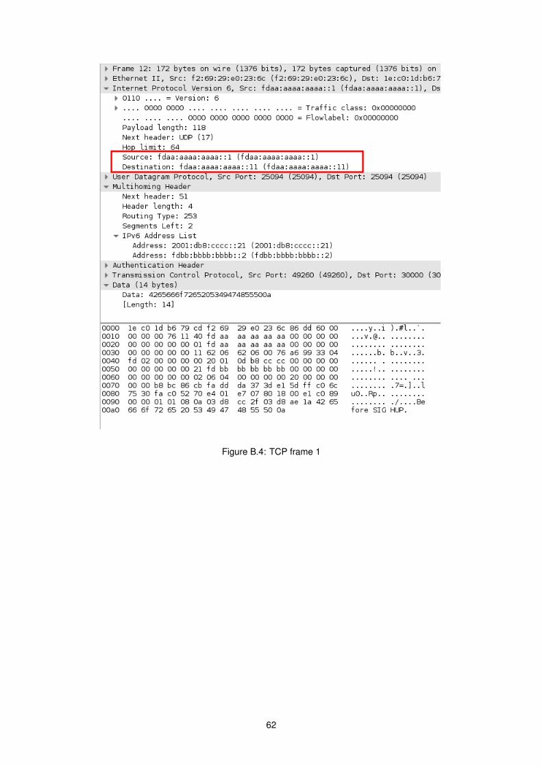
Figure B.4: TCP frame 1
62

Figure B.5: TCP frame 2
63
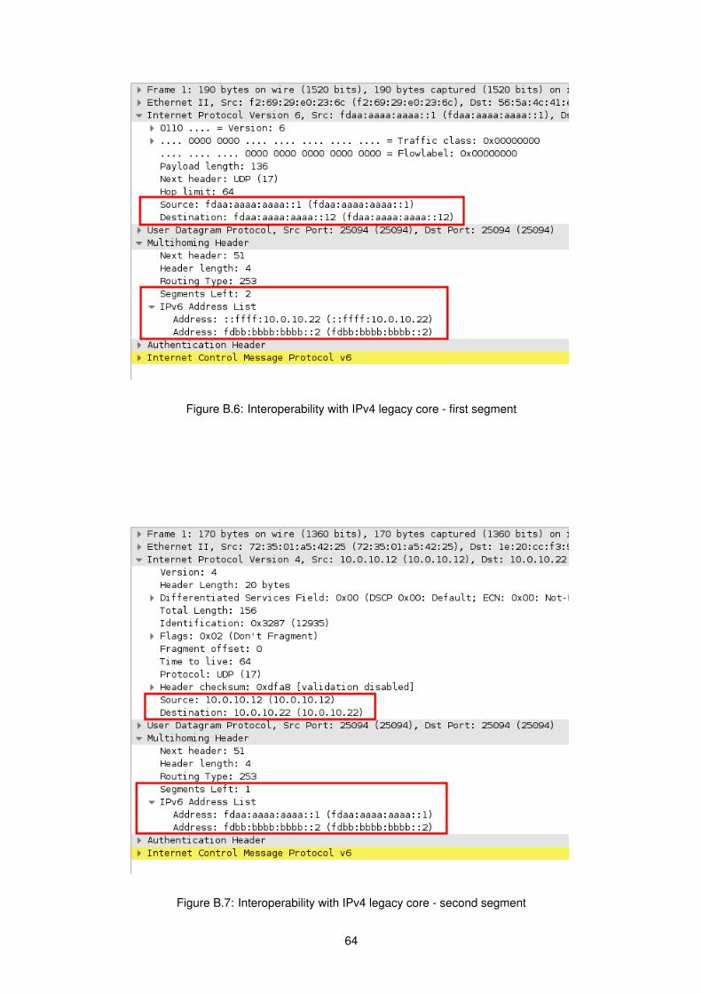
Figure B.6: Interoperability with IPv4 legacy core - first segment
Figure B.7: Interoperability with IPv4 legacy core - second segment
64

Figure B.8: Interoperability with IPv4 legacy core - third segment
Figure B.9: ICMPv6 error packet
65