Embed Size (px)
Citation preview

IPv6 Configurations and Test Lab
Microsoft Corporation Published: September 2002
Abstract
The Microsoft Windows® .NET Server family and Windows XP with Service Pack 1 include a supported version of the new IP version 6 (IPv6) protocol. This article describes five IPv6 configurations and instructions on how to
create an IPv6 test lab so that application developers can test their modified applications with a supported
protocol suite and Windows networking professionals to begin learning and experimenting with IPv6 prior to deploying IPv6 in their organizations.

Microsoft® Windows® .NET Server 2003 White Paper
This is a preliminary document and may be changed substantially prior to final commercial release of the software described herein.
The information contained in this document represents the current view of Microsoft Corporation on the issues discussed as of the date of publication. Because Microsoft must respond to changing market conditions, it should not be interpreted to be a commitment on the part of Microsoft, and Microsoft cannot guarantee the accuracy of any information presented after the date of publication.
This document is for informational purposes only. MICROSOFT MAKES NO WARRANTIES, EXPRESS OR IMPLIED, AS TO THE INFORMATION IN THIS DOCUMENT.
Complying with all applicable copyright laws is the responsibility of the user. Without limiting the rights under copyright, no part of this document may be reproduced, stored in or introduced into a retrieval system, or transmitted in any form or by any means (electronic, mechanical, photocopying, recording, or otherwise), or for any purpose, without the express written permission of Microsoft Corporation.
Microsoft may have patents, patent applications, trademarks, copyrights, or other intellectual property rights covering subject matter in this document. Except as expressly provided in any written license agreement from Microsoft, the furnishing of this document does not give you any license to these patents, trademarks, copyrights, or other intellectual property.
© 2002 Microsoft Corporation. All rights reserved.
Microsoft and Windows are either registered trademarks or trademarks of Microsoft Corporation in the United States and/or other countries.
The names of actual companies and products mentioned herein may be the trademarks of their respective owners.
Microsoft® Windows® .NET Server 2003 White Paper
iii
Contents
Introduction ...................................................................................................................................1
Single Subnet with Link-local Addresses......................................................................................3
Testing Connectivity Between Two Link-local Hosts........................................................................4
Using the Zone ID ........................................................................................................................5
Using IPSec Between Two Local Link Hosts..................................................................................6
Table 1 Security Policy Entry for Host 1...................................................................................6
Table 2 First Security Association Entry for Host 1....................................................................6
Table 3 Second Security Association Entry for Host 1...............................................................7
Table 4 Security Policy Entry for Host 2...................................................................................8
Table 5 First Security Association Entry for Host 2....................................................................9
Table 6 Second Security Association Entry for Host 2...............................................................9
IPv6 Traffic Between Nodes on Different Subnets of an IPv6 Internetwork..................................11
IPv6 Traffic Across an IPv4 Intranet.............................................................................................13
Table 7 Example ISATAP Addresses.....................................................................................14
Using an ISATAP Router ............................................................................................................14
Resolving the ISATAP Name ...................................................................................................15
Using the netsh interface ipv6 isatap set router Command .........................................................15
IPv6 Traffic Across the IPv4 Internet............................................................................................17
Setting up an IPv6 Test Lab.........................................................................................................20
Setting Up the Infrastructure........................................................................................................20
DNS1.....................................................................................................................................21
CLIENT1 ................................................................................................................................21
ROUTER1..............................................................................................................................22
ROUTER2..............................................................................................................................22
CLIENT2 ................................................................................................................................23
IPv6 Test Lab Tasks...................................................................................................................23
Link-local ping.........................................................................................................................23
Creating a static routing infrastructure ......................................................................................24
Using name resolution.............................................................................................................25

Microsoft® Windows® .NET Server 2003 White Paper
iv
Using temporary addresses .....................................................................................................26
Summary .....................................................................................................................................28
Related Links...............................................................................................................................29

Microsoft® Windows® .NET Server 2003 White Paper
IPv6 Configurations and Test Lab 1
Introduction
IP version 6 (IPv6) is a suite of standard protocols that is the next generation of network layer protocols for the Internet. The current version of the Internet Protocol (known as IP version 4 or IPv4) has not been substantially changed since RFC 791 was published in 1981. IPv4 has proven to be robust, easily implemented and interoperable, and has stood the test of scaling an internetwork to a global utility the size of today's Internet.
However, the initial design of IPv4 did not anticipate:
• The recent exponential growth of the Internet and the impending exhaustion of the IPv4 address space.
• Internet growth and the ability of Internet backbone routers to maintain large routing tables.
• The need for simpler configuration.
• The requirement for security at the IP level.
• The need for better support for real-time delivery of data (also known as quality of service).
To address these concerns, the Internet Engineering Task Force (IETF) has developed a suite of protocols and standards known as IP version 6 (IPv6). This new version, previously named IP-The Next Generation (IPng), incorporates the concepts of many proposed methods for updating the IPv4 protocol. IPv6 is intentionally designed for minimal impact on upper and lower layer protocols by avoiding the arbitrary addition of new features.
In order to justify the deployment of IPv6, it must be used by applications. Applications must be modified to use new Windows Sockets application programming interfaces (APIs) that are IP version independentthe same API function is used for IPv4 or IPv6, and the result of the API call depends on the installed protocols and the available addresses. For more information about modifying applications to work over IPv4 and IPv6, see the white paper titled "Adding IPv6 Capability to Windows Sockets Applications" and the Microsoft IPv6 Web site at http://www.microsoft.com/ipv6.
The Windows .NET Server 2003 family and Windows XP with Service Pack 1 (SP1) includes a supported IPv6 protocol suite that includes a number of features that allow you to set up and test IPv6 functionality either using native IPv6 packets or by sending IPv6 packets over an IPv4 routing infrastructure. Separate sections of this article describe the following configurations:
• Single subnet with link-local addresses.
• Using IPSec between two local link hosts.
• IPv6 traffic between nodes on different subnets of an IPv6 internetwork.
• IPv6 traffic across an IPv4 intranet.
• IPv6 traffic across the IPv4 Internet.
Additionally, this article contains instructions on how to use five computers to create a working IPv6 test lab network.
Note: This article assumes familiarity with IPv6 concepts, protocols, and addressing. For information, see the white paper titled

Microsoft® Windows® .NET Server 2003 White Paper
IPv6 Configurations and Test Lab 2
"Introduction to IP Version 6" at http://www.microsoft.com/windows2000/techinfo/howitworks/communications/nameadrmgmt/introipv6.asp.
Microsoft® Windows® .NET Server 2003 White Paper
IPv6 Configurations and Test Lab 3
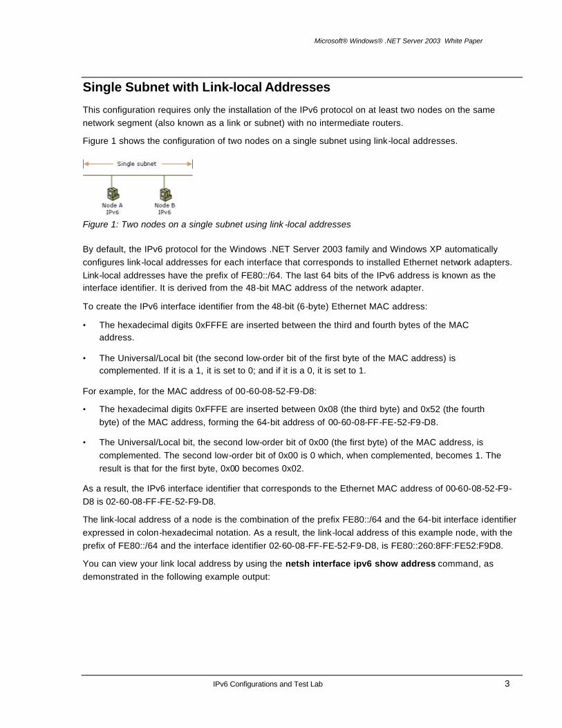
Single Subnet with Link-local Addresses
This configuration requires only the installation of the IPv6 protocol on at least two nodes on the same network segment (also known as a link or subnet) with no intermediate routers.
Figure 1 shows the configuration of two nodes on a single subnet using link-local addresses.
Figure 1: Two nodes on a single subnet using link -local addresses
By default, the IPv6 protocol for the Windows .NET Server 2003 family and Windows XP automatically configures link-local addresses for each interface that corresponds to installed Ethernet network adapters. Link-local addresses have the prefix of FE80::/64. The last 64 bits of the IPv6 address is known as the interface identifier. It is derived from the 48-bit MAC address of the network adapter.
To create the IPv6 interface identifier from the 48-bit (6-byte) Ethernet MAC address:
• The hexadecimal digits 0xFFFE are inserted between the third and fourth bytes of the MAC address.
• The Universal/Local bit (the second low-order bit of the first byte of the MAC address) is complemented. If it is a 1, it is set to 0; and if it is a 0, it is set to 1.
For example, for the MAC address of 00-60-08-52-F9-D8:
• The hexadecimal digits 0xFFFE are inserted between 0x08 (the third byte) and 0x52 (the fourth byte) of the MAC address, forming the 64-bit address of 00-60-08-FF-FE-52-F9-D8.
• The Universal/Local bit, the second low-order bit of 0x00 (the first byte) of the MAC address, is complemented. The second low-order bit of 0x00 is 0 which, when complemented, becomes 1. The result is that for the first byte, 0x00 becomes 0x02.
As a result, the IPv6 interface identifier that corresponds to the Ethernet MAC address of 00-60-08-52-F9-D8 is 02-60-08-FF-FE-52-F9-D8.
The link-local address of a node is the combination of the prefix FE80::/64 and the 64-bit interface identifier expressed in colon-hexadecimal notation. As a result, the link-local address of this example node, with the prefix of FE80::/64 and the interface identifier 02-60-08-FF-FE-52-F9-D8, is FE80::260:8FF:FE52:F9D8.
You can view your link local address by using the netsh interface ipv6 show address command, as demonstrated in the following example output:

Microsoft® Windows® .NET Server 2003 White Paper
IPv6 Configurations and Test Lab 4
Interface 3: Local Area Connection Addr Type DAD State Valid Life Pref. Life Address --------- ---------- ------------ ------------ --------------------------- Link Preferred infinite infinite fe80::204:5aff:fe56:1006 Interface 2: Automatic Tunneling Pseudo-Interface Addr Type DAD State Valid Life Pref. Life Address --------- ---------- ------------ ------------ --------------------------- Link Preferred infinite infinite fe80::5efe:10.60.137.151 Interface 1: Loopback Pseudo-Interface Addr Type DAD State Valid Life Pref. Life Address --------- ---------- ------------ ------------ --------------------------- Loopback Preferred infinite infinite ::1 Link Preferred infinite infinite fe80::1 Local Area Connection is an interface that corresponds to an installed Ethernet adapter with a link-local address of FE80::204:5AFF:FE56:FA4.
The IPv6 protocol for the Windows .NET Server 2003 family and Windows XP identifies an interface with either a name or an interface index, which is a number assigned to an interface by the IPv6 protocol. In the display of the netsh interface ipv6 show address command, the interface index is the number after "Interface." For example, in the previous display, the interface index of the Local Area Connection interface is 3.
Testing Connectivity Between Two Link-local Hosts You can perform a simple ping (an exchange of ICMPv6 Echo Request and Echo Reply messages) with IPv6 between two link-local hosts by completing the following steps:
1. Use the netsh interface ipv6 install command to install the IPv6 protocol on two host computers (Host A and Host B) that are on the same link. For the Windows .NET Server 2003 family and for Windows XP with SP1, you can also add the IPv6 protocol using Network Connections.
2. Use netsh interface ipv6 show address on Host A to obtain the link-local address and the interface index for the interface named Local Area Connection.
For example, the link-local address of Host A is FE80::210:5AFF:FEAA:20A2 and the interface index of the named Local Area Connection is 4.
3. Use netsh interface ipv6 show address on Host B to obtain the link-local address and the interface index for the interface named Local Area Connection.
For example, the link-local address of Host B is FE80::260:97FF:FE02:6EA5 and the interface index for the named Local Area Connection is 5.
4. From Host A, use Ping.exe to ping Host B using the interface index of Host A's Local Area Connection interface.
For example, to ping Host B using our example addresses and interface index, the command is ping fe80::260:97ff:fe02:6ea5%4.
Note: The use of lowercase alphabetic characters for IPv6 addresses and prefixes in Netsh and other commands in this document is by convention only. You can use either upper or lower case.
Note: The ping command for the IPv6 protocol for Windows XP (prior to Service Pack 1) does not support IPv6 addresses. Use the

Microsoft® Windows® .NET Server 2003 White Paper
IPv6 Configurations and Test Lab 5
ping6 command instead.
Using the Zone ID When you specify a link-local destination address, you must specify the zone ID to make the zone, the area of the network, for the traffic specific. When you specify a site-local destination address, you might have to specify the zone ID. Zone IDs are not needed for global addresses.
For example, on a computer with multiple Ethernet adapters that are connected to separate links, each Ethernet adapter is assigned a link-local address. Destination link-local addresses in this configuration are ambiguous because a specific link-local address can be assigned to multiple nodes located on the links that are reachable from all of the installed Ethernet adapters. To define the area of the network for which the destination is intended, the zone ID is used to select the link over which traffic is sent and received. In the IPv6 protocol for the Windows .NET Server 2003 family and Windows XP, the zone ID for link -local addresses is typically the interface index from the display of the netsh interface ipv6 show interface command. The interface index is defined locally on each IPv6 host. Because of this, the interface index used by Host A to reach Host B might not be the same as the interface index used by Host B to reach Host A.
When using site-local addresses, it is possible to be connected to multiple sites. In this case, each site is assigned a site identifier. To define the area of the network for which the destination is intended, the zone ID is used to indicate the site identifier. For the IPv6 protocol for the Windows .NET Server 2003 family or Windows XP, the zone ID is the "Zone ID for Site" from the display of the netsh interface ipv6 show interface level=verbose command. If you are connected only to a single site, the default site identifier is 1 and the zone ID does not have to be specified. The site identifier is defined locally on each IPv6 host. Because of this, the site identifier used by Host A to reach Host B might not be the same as the site identifier used by Host B to reach Host A.
The notation that is used to specify the zone ID with an address is Address%ZoneID, in which Address is a link-local or site-local IPv6 address and ZoneID is the zone ID, typically either an interface index or site identifier.
Microsoft® Windows® .NET Server 2003 White Paper
IPv6 Configurations and Test Lab 6
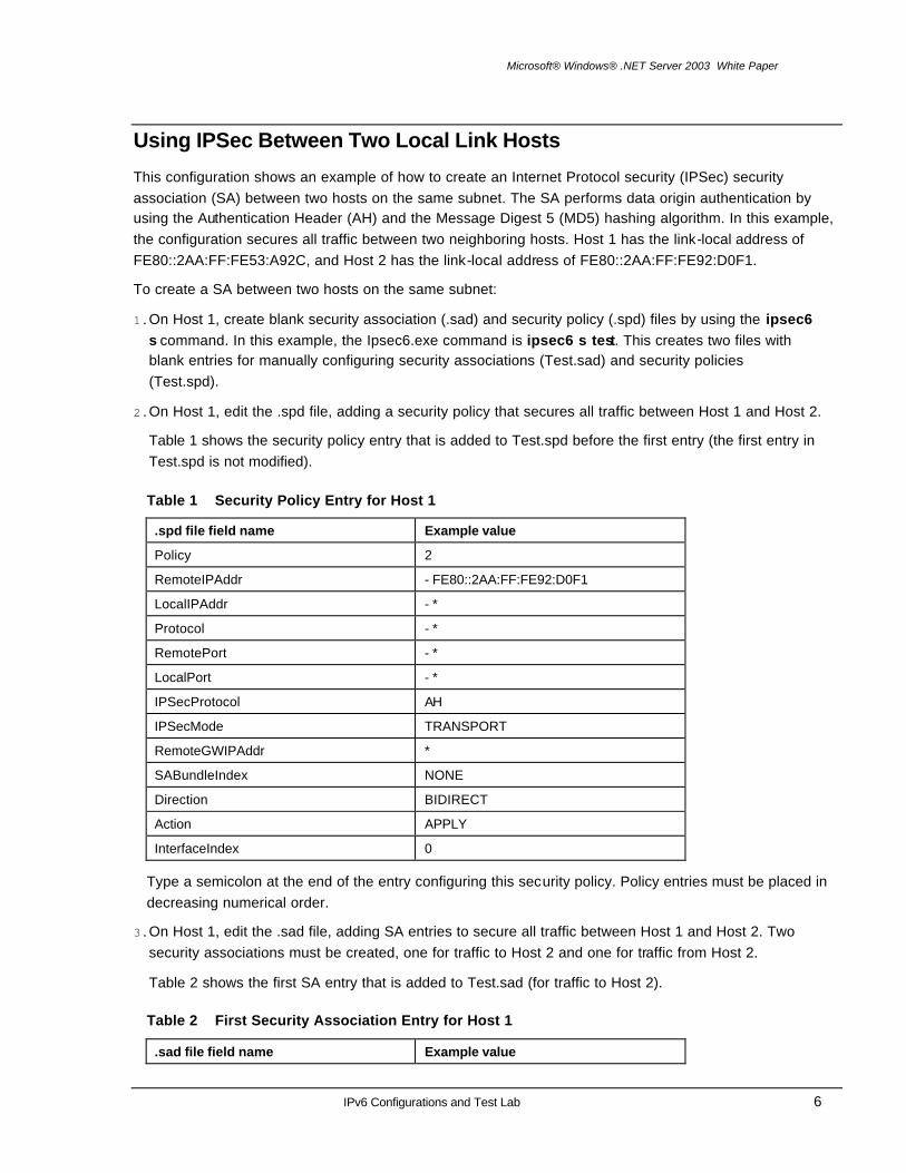
Using IPSec Between Two Local Link Hosts
This configuration shows an example of how to create an Internet Protocol security (IPSec) security association (SA) between two hosts on the same subnet. The SA performs data origin authentication by using the Authentication Header (AH) and the Message Digest 5 (MD5) hashing algorithm. In this example, the configuration secures all traffic between two neighboring hosts. Host 1 has the link-local address of FE80::2AA:FF:FE53:A92C, and Host 2 has the link-local address of FE80::2AA:FF:FE92:D0F1.
To create a SA between two hosts on the same subnet:
1. On Host 1, create blank security association (.sad) and security policy (.spd) files by using the ipsec6 s command. In this example, the Ipsec6.exe command is ipsec6 s test. This creates two files with blank entries for manually configuring security associations (Test.sad) and security policies (Test.spd).
2. On Host 1, edit the .spd file, adding a security policy that secures all traffic between Host 1 and Host 2.
Table 1 shows the security policy entry that is added to Test.spd before the first entry (the first entry in Test.spd is not modified).
Table 1 Security Policy Entry for Host 1
.spd file field name Example value
Policy 2
RemoteIPAddr - FE80::2AA:FF:FE92:D0F1
LocalIPAddr - *
Protocol - *
RemotePort - *
LocalPort - *
IPSecProtocol AH
IPSecMode TRANSPORT
RemoteGWIPAddr *
SABundleIndex NONE
Direction BIDIRECT
Action APPLY
InterfaceIndex 0
Type a semicolon at the end of the entry configuring this security policy. Policy entries must be placed in decreasing numerical order.
3. On Host 1, edit the .sad file, adding SA entries to secure all traffic between Host 1 and Host 2. Two security associations must be created, one for traffic to Host 2 and one for traffic from Host 2.
Table 2 shows the first SA entry that is added to Test.sad (for traffic to Host 2).
Table 2 First Security Association Entry for Host 1
.sad file field name Example value

Microsoft® Windows® .NET Server 2003 White Paper
IPv6 Configurations and Test Lab 7
SAEntry 2
SPI 3001
SADestIPAddr FE80::2AA:FF:FE92:D0F1
DestIPAddr POLICY
SrcIPAddr POLICY
Protocol POLICY
DestPort POLICY
SrcPort POLICY
AuthAlg HMAC-MD5
KeyFile Test.key
Direction OUTBOUND
SecPolicyIndex 2
Type a semicolon at the end of the entry configuring this SA.
Table 3 shows the second SA entry that is added to Test.sad (for traffic from Host 2).
Table 3 Second Security Association Entry for Host 1
.sad file field name Example value
SAEntry 1
SPI 3000
SADestIPAddr FE80::2AA:FF:FE53:A92C
DestIPAddr POLICY
SrcIPAddr POLICY
Protocol POLICY
DestPort POLICY
SrcPort POLICY
AuthAlg HMAC-MD5
KeyFile Test.key
Direction INBOUND
SecPolicyIndex 2
Type a semicolon at the end of the entry configuring this SA. SA entries must be placed in decreasing numerical order.
4. On Host 1, create a file that contains data used to create and validate the Message Digest 5 (MD5) keyed hash on each IPSec-protected packet that is exchanged with Host 2. In this example, a text file is used. Test.key is created with the contents "This is a test." with no extra characters, spaces, or lines.
The IPv6 protocol for the Windows .NET Server 2003 family and Windows XP supports only manually configured keys for quick mode SAs (also known as IPSec or Phase II SAs), because main mode negotiation through Internet Key Exchange (IKE) is not performed. Manual keys are configured by creating files that contain either the text or binary data of the manual key. In this example, the same key

Microsoft® Windows® .NET Server 2003 White Paper
IPv6 Configurations and Test Lab 8
for the SAs is used in both directions. You can use different keys for inbound and outbound SAs by creating different key files and referencing them with the KeyFile field in the .sad file.
5. On Host 2, use the ipsec6 s command to create blank security association (.sad) and security policy (.spd) files. In this example, the Ipsec6.exe command is ipsec6 s test. This creates two files with blank entries for manually configuring security associations (Test.sad) and security policies (Test.spd).
To simplify the example, the same file names for the .sad and .spd files are used on Host 2. You can choose to use different file names on each host.
6. On Host 2, edit the .spd file, adding a security policy that secures all traffic between Host 2 and Host 1.
Table 4 shows the security policy entry that is added to Test.spd before the first entry (the first entry in Test.spd is not modified).
Table 4 Security Policy Entry for Host 2
.spd file field name Example value
Policy 2
RemoteIPAddr - FE80::2AA:FF:FE53:A92C
LocalIPAddr - *
Protocol - *
RemotePort - *
LocalPort - *
IPSecProtocol AH
IPSecMode TRANSPORT
RemoteGWIPAddr *
SABundleIndex NONE
Direction BIDIRECT
Action APPLY
InterfaceIndex 0
Type a semicolon at the end of the entry configuring this security policy. Policy entries must be placed in decreasing numerical order.
7. On Host 2, edit the .sad file, adding SA entries to secure all traffic between Host 2 and Host 1. Two security associations must be created: one for traffic to Host 1 and one for traffic from Host 1.
Table 5 shows the first SA entry that is added to Test.sad (for traffic to Host 1).

Microsoft® Windows® .NET Server 2003 White Paper
IPv6 Configurations and Test Lab 9
Table 5 First Security Association Entry for Host 2
.sad file field name Example value
SAEntry 2
SPI 3000
SADestIPAddr FE80::2AA:FF:FE53:A92C
DestIPAddr POLICY
SrcIPAddr POLICY
Protocol POLICY
DestPort POLICY
SrcPort POLICY
AuthAlg HMAC-MD5
KeyFile Test.key
Direction OUTBOUND
SecPolicyIndex 2
Type a semicolon at the end of the entry configuring this SA.
The following table shows the second SA entry that is added to Test.sad (for traffic from Host 1):
Table 6 Second Security Association Entry for Host 2
.sad file field name Example value
SAEntry 1
SPI 3001
SADestIPAddr FE80::2AA:FF:FE92:D0F1
DestIPAddr POLICY
SrcIPAddr POLICY
Protocol POLICY
DestPort POLICY
SrcPort POLICY
AuthAlg HMAC-MD5
KeyFile Test.key
Direction INBOUND
SecPolicyIndex 2
Type a semicolon at the end of the entry configuring this SA. SA entries must be placed in decreasing numerical order.
8. On Host 2, create a text file that contains a text string that is used to authenticate the SAs created with Host 1. In this example, Test.key is created with the contents "This is a test." with no extra characters, spaces, or lines.
9. On Host 1, use the ipsec6 l command to add the configured security policies and SAs from the .spd and .sad files. In this example, the ipsec6 l test command is run on Host 1.
Microsoft® Windows® .NET Server 2003 White Paper
IPv6 Configurations and Test Lab 10
10.On Host 2, use the ipsec6 l command to add the configured security policies and SAs from the .spd and .sad files. In this example, the ipsec6 l test command is run on Host 2.
11.On Host 2, use the ping command to ping Host 1.
If you use Network Monitor to capture the traffic, you should see the exchange of ICMPv6 Echo Request and Echo Reply messages, with an Authentication Header (AH) between the IPv6 header and the ICMPv6 header.
To remove the IPSec settings for this example, type the following commands on both Host 1 and Host 2:
ipsec6 d sp 2
ipsec6 d sa 1
ipsec6 d sa 2

Microsoft® Windows® .NET Server 2003 White Paper
IPv6 Configurations and Test Lab 11
IPv6 Traffic Between Nodes on Different Subnets of an IPv6 Internetwork
This configuration requires three computers (two hosts and one router computer) and additional router configuration beyond the installation of the IPv6 protocol. There are two separate network segments (also known as links or subnets) and an IPv6-capable router that forwards IPv6 packets between hosts on the segments.
Figure 2 shows the configuration of two hosts on separate network segments that are connected by a router.
Figure 2: Two hosts on separate network segments connected by a router
By default, the IPv6 protocol for the Windows .NET Server 2003 family and Windows XP configures link-local IP addresses for each LAN interface that corresponds to Ethernet or FDDI network adapters. Link-local addresses have the prefix of FE80::/64. The last 64 bits of the IPv6 address are the interface identifier, as derived from the 48-bit MAC address of the network adapter. With link-local addresses, Host A and Host B can communicate with the router computer, but not with each other.
In this configuration, the router advertises additional site-local prefixes. The site-local prefixes are used by Host A and Host B to automatically configure site-local addresses that are derived from the 48-bit MAC address of the network adapter. After Host A and Host B have site-local addresses, they can communicate with each other.
On the router computer, type the netsh interface ipv6 show interface command to obtain the interface names and index numbers of the two network adapters. Subnet 1 is the network segment to which Host A is attached. Subnet 2 is the network segment to which Host B is attached.
After you have obtained the names and interface index numbers, type the following commands on the router computer:
netsh interface ipv6 set interface Subnet1InterfaceNameOrIndex forwarding=enabled advertise=enabled
netsh interface ipv6 set interface Subnet2InterfaceNameOrIndex forwarding=enabled advertise=enabled
netsh interface ipv6 add route fec0:0:0:1::/64 Subnet1InterfaceNameOrIndex publish=yes
netsh interface ipv6 add route fec0:0:0:2::/64 Subnet2InterfaceNameOrIndex publish=yes
Microsoft® Windows® .NET Server 2003 White Paper
IPv6 Configurations and Test Lab 12
where:
• Subnet1InterfaceNameOrIndex is either the name or interface index of the router computer's network adapter that is attached to Subnet 1
• Subnet2InterfaceNameOrIndex is either the name or interface index of the router computer's network adapter that is attached to Subnet 2
For example, if the names of the interfaces attached to Subnet 1 and Subnet 2 are "Local Area Connection" and "Local Area Connection 2" respectively, the commands are:
netsh interface ipv6 set interface "Local Area Connection" forwarding=enabled advertise=enabled
netsh interface ipv6 set interface "Local Area Connection 2" forwarding=enabled advertise=enabled
netsh interface ipv6 add route fec0:0:0:1::/64 "Local Area Connection" publish=yes
netsh interface ipv6 add route fec0:0:0:2::/64 "Local Area Connection 2" publish=yes
You should wait about 30 seconds for the router computer to advertise new site-local prefixes on Subnets 1 and 2, and for Hosts A and B to automatically configure site-local addresses based on these prefixes.
On Host A, type the netsh interface ipv6 show interface command to check for a new IPv6 address for the Ethernet adapter that is based on the site-local prefix of FEC0:0:0:1::/64. On Host B, type the netsh interface ipv6 show interface command to check for a new IPv6 address for the Ethernet adapter that is based on the site-local prefix of FEC0:0:0:2::/64.
On Host A, use the ping command and the site-local address of Host B to ping Host B. For example, if the Host B site-local address is FEC0::2:260:97FF:FE02:6EA5, the command is ping fec0::2:260:97ff:fe02:6ea5.
Microsoft® Windows® .NET Server 2003 White Paper
IPv6 Configurations and Test Lab 13
IPv6 Traffic Across an IPv4 Intranet
The IPv6 protocol for the Windows .NET Server 2003 and Windows XP provides the following methods for communicating between IPv6 nodes on different subnets of an IPv4 intranet:
• Using Intra-site Automatic Tunnel Addressing Protocol (ISATAP) addresses
ISATAP allows IPv6/IPv4 hosts to exchange unicast IPv6 traffic over an IPv4 intranet. ISATAP is enabled by default.
• Using 6over4
6over4 allows IPv6/IPv4 hosts to exchange unicast and multicast IPv6 traffic over an IPv4 intranet. However, 6over4 requires that the IPv4 intranet be multicast-capable. Because most IPv4 intranets are not multicast-capable, 6over4 is rarely used. For more information, see RFC 2529. 6over4 is disabled by default.
Note: Although IPv6 packets are being carried as the payload of an IPv4 packet (treating the IPv4 infrastructure as an IPv6 link layer), it is still IPv6 traffic. Applications that use the addresses associated with these methods are using the same Windows Sockets functions as if global IPv6 addresses and an IPv6 infrastructure were being used. You can use these methods to test IPv6 functionality for your applications without having to deploy IPv6-capable routers in your organization.
ISATAP is an address assignment and automatic tunneling technology that is used to provide unicast IPv6 connectivity between IPv6 hosts across an IPv4 intranet. ISATAP is described in the Internet draft titled "Intra-Site Automatic Tunnel Addressing Protocol (ISATAP)" (draft -ietf-ngtrans-isatap-0x.txt). ISATAP addresses use the locally administered interface ID ::0:5EFE:w.x.y.z where:
• The 0:5EFE portion denotes an ISATAP interface ID.
• The w.x.y.z portion is any unicast IPv4 address, which includes both public and private addresses.
The ISATAP interface ID can be combined with any 64-bit prefix that is valid for IPv6 unicast addresses. This includes the link-local address prefix (FE80::/64), site-local prefixes, and global prefixes (including 6to4 prefixes).
ISATAP addresses contain an embedded IPv4 address that is used to determine either source or destination IPv4 addresses within the IPv4 header when ISATAP-addressed IPv6 traffic is tunneled across an IPv4 network.
By default, the IPv6 protocol for the Windows .NET Server 2003 family and Windows XP automatically configures an ISATAP address of FE80::5EFE:w.x.y.z on the Automatic Tunneling Pseudo-Interface (interface index 2) for each IPv4 address that is assigned to the node. This link-local ISATAP address allows two hosts to communicate over an IPv4 network by using each other's link-local ISATAP address. For an example, see the example output of the netsh interface ipv6 show address command in "Single subnet with link-local addresses" in this article.
For example, Host A is configured with the IPv4 address of 10.40.1.29 and Host B is configured with the IPv4 address of 192.168.41.30. When the IPv6 protocol for the Windows .NET Server 2003 family and Windows XP is started, Host A is automatically configured with the ISATAP address of FE80::5EFE:10.40.1.29 and Host B is automatically configured with the ISATAP address of

Microsoft® Windows® .NET Server 2003 White Paper
IPv6 Configurations and Test Lab 14
FE80::5EFE:192.168.41.30. When Host A sends IPv6 traffic to Host B by using Host B's ISATAP address, the source and destination addresses for the IPv4 and IPv6 headers are listed in Table 7.
Table 7 Example ISATAP Addresses
Field Value
IPv6 Source Address FE80::5EFE:10.40.1.29
IPv6 Destination Address FE80::5EFE:192.168.41.30
IPv4 Source Address 10.40.1.29
IPv4 Destination Address 192.168.41.30
To test connectivity, use the ping command. For example, Host A would use the following command to ping Host B by using its link-local ISATAP address:
ping fe80::5efe:192.168.41.30%2
Because the destination of the ping command is a link-local address, the %ZoneID portion of the command is used to specify the interface index of the link from which traffic is sent. In this case, %2 specifies link 2, which is the link ID assigned to the Automatic Tunneling Pseudo-Interface on Host A.
Using an ISATAP Router The use of link-local ISATAP addresses allows IPv6/IPv4 hosts on the same logical IPv6 subnet (an IPv4 network) to communicate with each other, but not with other IPv6 addresses on other subnets. To communicate outside the logical IPv6 subnet using ISATAP-derived global addresses, IPv6 hosts using ISATAP addresses must tunnel their packets to an ISATAP router.
An ISATAP router is an IPv6 router that performs the following:
• Forwards packets between ISATAP hosts on a logical IPv6 subnet (an IPv4 intranet) and hosts on other subnets.
The other subnets can be other IPv4 networks (such as another portion of an organization's IPv4 network or the IPv4 Internet) or subnets in a native IPv6 routing domain (such as an organization's IPv6 network or the IPv6 Internet).
• Acts as a default router for ISATAP hosts.
• Advertises address prefixes to identify the logical IPv6 subnet on which ISATAP hosts are located. ISATAP hosts use the advertised address prefixes to configure site-local and global ISATAP addresses.
When an ISATAP host receives a router advertisement from an ISATAP router that is acting as a default router, a default route (::/0) is added using the Automatic Tunneling Pseudo-Interface and with next-hop address set to the link-local ISATAP address that corresponds to the logical subnet interface of the ISATAP router. When packets destined to locations outside the logical subnet are sent, they are tunneled to the IPv4 address of the ISATAP router corresponding to the ISATAP router's interface on the logical IPv6 subnet defined by the IPv4 intranet containing the ISATAP router and ISATAP host. The ISATAP router then forwards the IPv6 packet.
For the IPv6 protocol for the Windows .NET Server 2003 family and Windows XP with SP1, the configuration of the intranet IPv4 address of the ISATAP router is obtained through either of the following:

Microsoft® Windows® .NET Server 2003 White Paper
IPv6 Configurations and Test Lab 15
• The successful resolution of the name "ISATAP" to an IPv4 address.
• The netsh interface ipv6 isatap set router command.
Note: The IPv6 protocol for Windows XP (prior to Service Pack 1) attempts to resolve the name "_ISATAP", rather than "ISATAP".
Resolving the ISATAP Name When the IPv6 protocol for the Windows .NET Server 2003 family and Windows XP with SP1 starts, it attempts to resolve the name ISATAP to an IPv4 address using normal TCP/IP host and NetBIOS name resolution techniques. If successful, the host sends an IPv4-encapsulated Router Solicitation message to the ISATAP router. The ISATAP router responds with an IPv4-encapsulated unicast Router Advertisement message advertising itself as a default router and containing prefixes to use for autoconfiguration of ISATAP-based addresses.
To ensure that the resolution of ISATAP is successful, you can do one of the following:
• If the ISATAP router is a computer running a member of the Windows .NET Server 2003 family or Windows XP, name the computer ISATAP and it will automatically attempt to register the appropriate records in DNS (provided DNS dynamic update is enabled on the DNS server of the ISATAP router) and WINS.
• Manually create an ISATAP address (A) record in the appropriate domain in DNS. For example, for the example.com domain, create an A record for isatap.example.com.
• Manually create a static WINS record in WINS for the NetBIOS name "ISATAP <00>".
• Add the following entry to the Hosts file of the computers that need to resolve the name ISATAP:
IPv4Address ISATAP
• Add the following entry to the Lmhosts file of the computers that need to resolve the name ISATAP:
IPv4Address ISATAP
Using the netsh interface ipv6 isatap se t router Command Although the automatic resolution of the ISATAP name is the recommended method for determining the IPv4 address of the ISATAP router, you can perform manual configuration with the netsh interface ipv6 isatap set router command. The syntax of this command is:
netsh interface ipv6 isatap set router RouterNameOrAddress
where RouterNameOrAddress is the name of the router that is resolved to the IPv4 address of the ISATAP router's intranet interface or the IPv4 address of the ISATAP router's intranet interface. For example, if the ISATAP router's IPv4 address is 192.168.39.1, the command is:
netsh interface ipv6 isatap set router 192.168.39.1
Once configured, the host sends an IPv4-encapsulated Router Solicitation message to the ISATAP router. The ISATAP router responds with an IPv4-encapsulated unicast Router Advertisement message containing prefixes to use for autoconfiguration of ISATAP-based addresses. This additional configuration is only needed when there is no IPv6 router on the host's subnet.
Note: The IPv6 protocol for Windows XP (prior to Service Pack 1) does not support the netsh interface ipv6 isatap set router command. Use the ipv6 rlu command instead.

Microsoft® Windows® .NET Server 2003 White Paper
IPv6 Configurations and Test Lab 16

Microsoft® Windows® .NET Server 2003 White Paper
IPv6 Configurations and Test Lab 17
IPv6 Traffic Across the IPv4 Internet
The IPv6 protocol for the Windows .NET Server 2003 and Windows XP provides the following methods for communicating between IPv6 hosts or sites across the IPv4 Internet:
• Using 6to4
6to4 allows IPv6/IPv4 hosts or IPv6 hosts within sites to exchange unicast IPv6 traffic over the IPv4 Internet. 6to4 is enabled by default.
• Using IPv4-compatible addresses
IPv4-compatible addresses allow IPv6/IPv4 hosts to exchange unicast IPv6 traffic over the IPv4 Internet. However, IPv4-compatible addresses are rarely used and are disabled by default.
6to4 is an address assignment and automatic tunneling technology that is used to provide unicast IPv6 connectivity between IPv6 sites and hosts across the IPv4 Internet. When 6to4 is used, IPv6 traffic is encapsulated with an IPv4 header before it is sent over the IPv4 Internet.
6to4 uses the global address prefix of 2002:WWXX:YYZZ::/48, where WWXX:YYZZ is both the Next Level Aggregator (NLA) portion of a global address and the colon-hexadecimal representation of a public IPv4 address (w.x.y.z) that is assigned to the site or host. The complete 6to4 address of a 6to4 host is 2002:WWXX:YYZZ:SLA_ID:Interface_ID.
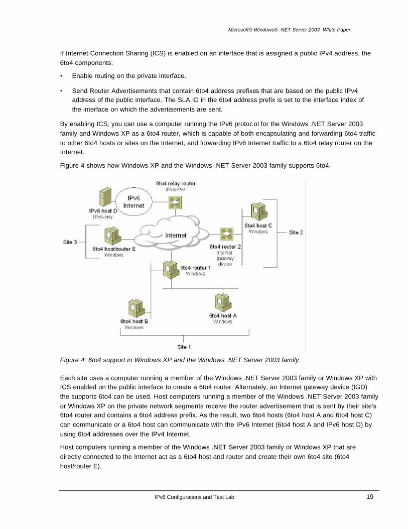
RFC 3056 defines the following terms:
• 6to4 host
An IPv6 host that is configured with at least one 6to4 address.
• 6to4 router
An IPv6/IPv4 router that forwards 6to4-addressed traffic between the 6to4 hosts within a site and other 6to4 routers or 6to4 relay routers on the Internet.
• 6to4 relay router
An IPv6/IPv4 router that forwards 6to4-addressed traffic between 6to4 routers on the Internet and hosts on the IPv6 Internet.
When you use 6to4 hosts, an IPv6 routing infrastructure within 6to4 sites, a 6to4 router at site boundaries, and a 6to4 relay router, the following types of communication are possible:
• A 6to4 host can communicate with another 6to4 host within the same site.
This type of communication is available through the IPv6 routing infrastructure, which provides reachability to all hosts within the site.
• A 6to4 host can communicate with 6to4 hosts in other sites across the IPv4 Internet.
This type of communication occurs when a 6to4 host forwards IPv6 traffic that is destined to a 6to4 host in another site to the local site 6to4 router. The local site 6to4 router encapsulates the IPv6 traffic with an IPv4 header and sends it to the 6to4 router at the destination site on the Internet. The 6to4 router at

Microsoft® Windows® .NET Server 2003 White Paper
IPv6 Configurations and Test Lab 18
the destination site removes the IPv4 header and forwards the IPv6 packet to the appropriate 6to4 host by using the IPv6 routing infrastructure of the destination site.
• A 6to4 host can communicate with hosts on the IPv6 Internet.
This type of communication occurs when a 6to4 host forwards IPv6 traffic that is destined for a IPv6 Internet host to the local site 6to4 router. The local site 6to4 router encapsulates the IPv6 traffic with an IPv4 header and sends it to a 6to4 relay router that is connected to both the IPv4 Internet and the IPv6 Internet. The 6to4 relay router removes the IPv4 header and forwards the IPv6 packet to the appropriate IPv6 Internet host by using the IPv6 routing infrastructure of the IPv6 Internet.
All of these types of communication use IPv6 traffic without the requirement of obtaining either a direct connection to the IPv6 Internet or an IPv6 global address prefix from an Internet service provider (ISP).
Figure 3 shows how 6to4 is used to communicate between 6to4 hosts, 6to4 sites, and the IPv6 Internet.
Figure 3: Using 6to4 to communicate between 6to4 hosts, 6to4 sites, and the IPv6 Internet
Support for 6to4 hosts and routers is provided in the 6to4 component that is included with the IP v6 protocol for the Windows .NET Server 2003 family and Windows XP. If an IPv6 router advertisement is not received (either from a router on a local link or from an ISATAP router) and the computer has a public IPv4 address assigned, the 6to4 component automatically performs the following:
• Creates an interface that is named 6to4 Tunneling Pseudo-Interface and configures 6to4 addresses on the interface for all public IPv4 addresses that are assigned to interfaces on the computer.
• Creates a 2002::/16 route that forwards all 6to4 traffic with the 6to4 Tunneling Pseudo-Interface. All traffic forwarded by this host to 6to4 destinations is encapsulated with an IPv4 header.
• Automatically determines the IPv4 address of a 6to4 relay router on the IPv4 Internet.
Through this automatic configuration, any host that is running the IPv6 protocol for the Windows .NET Server 2003 family and Windows XP is automatically configured as a 6to4 host. A 6to4 host can perform its own tunneling to reach 6to4 hosts in other sites or hosts on the IPv6 Internet.
Microsoft® Windows® .NET Server 2003 White Paper
IPv6 Configurations and Test Lab 19
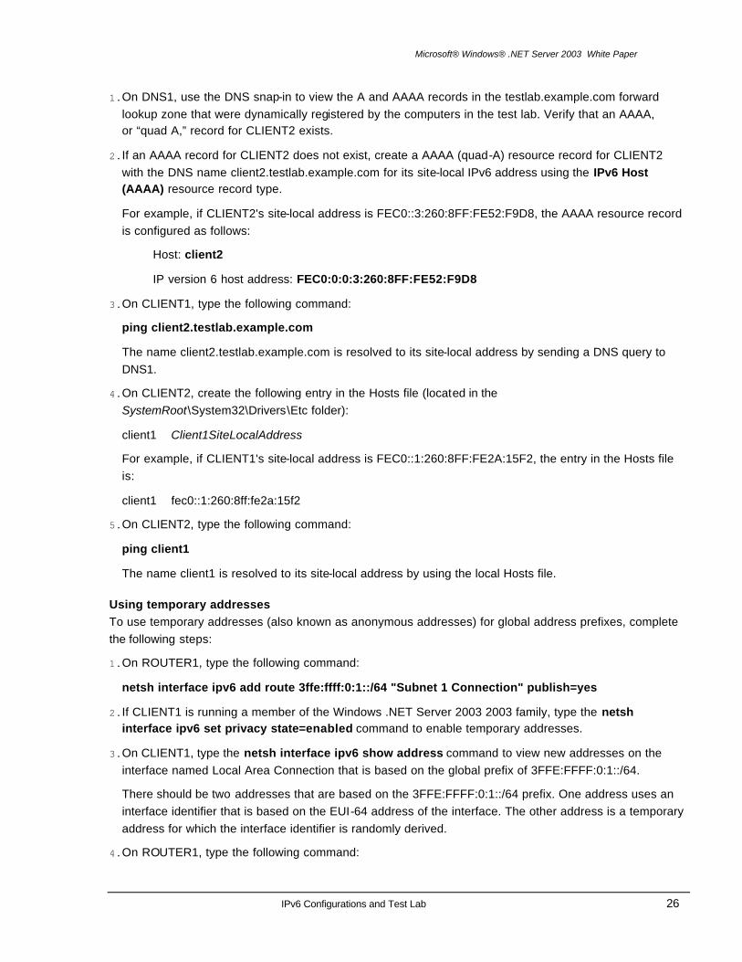
If Internet Connection Sharing (ICS) is enabled on an interface that is assigned a public IPv4 address, the 6to4 components:
• Enable routing on the private interface.
• Send Router Advertisements that contain 6to4 address prefixes that are based on the public IPv4 address of the public interface. The SLA ID in the 6to4 address prefix is set to the interface index of the interface on which the advertisements are sent.
By enabling ICS, you can use a computer running the IPv6 protoc ol for the Windows .NET Server 2003 family and Windows XP as a 6to4 router, which is capable of both encapsulating and forwarding 6to4 traffic to other 6to4 hosts or sites on the Internet, and forwarding IPv6 Internet traffic to a 6to4 relay router on the Internet.
Figure 4 shows how Windows XP and the Windows .NET Server 2003 family supports 6to4.
Figure 4: 6to4 support in Windows XP and the Windows .NET Server 2003 family
Each site uses a computer running a member of the Windows .NET Server 2003 family or Windows XP with ICS enabled on the public interface to create a 6to4 router. Alternately, an Internet gateway device (IGD) the supports 6to4 can be used. Host computers running a member of the Windows .NET Server 2003 family or Windows XP on the private network segments receive the router advertisement that is sent by their site's 6to4 router and contains a 6to4 address prefix. As the result, two 6to4 hosts (6to4 host A and 6to4 host C) can communicate or a 6to4 host can communicate with the IPv6 Internet (6to4 host A and IPv6 host D) by using 6to4 addresses over the IPv4 Internet.
Host computers running a member of the Windows .NET Server 2003 family or Windows XP that are directly connected to the Internet act as a 6to4 host and router and create their own 6to4 site (6to4 host/router E).

Microsoft® Windows® .NET Server 2003 White Paper
IPv6 Configurations and Test Lab 20
Setting up an IPv6 Test Lab
This section provides information about how you can use five computers to create a test lab to configure and test the IPv6 protocol for the Windows .NET Server 2003 family and Windows XP. These instructions are designed to walk you through a set of tasks, exposing you to the IPv6 protocol and its associated functionality. Beyond the set of tasks, these instructions leave you with a functioning IPv6 configuration. You can use this configuration to learn about and experiment with IPv6 features and functionality, and to aid in developing applications for IPv6 or modifying existing IPv4 applications to work over both IPv4 and IPv6.
Setting Up the Infrastructure The infrastructure for the IPv6 test lab network consists of five computers performing the following services:
• A computer running a member of the Windows 2000 or Windows .NET Server 2003 families that is used as a Domain Name System (DNS) server. This computer is named DNS1.
• A computer running a member of the Windows .NET Server 2003 family or Windows XP that is used as a client. This computer is named CLIENT1.
• A computer running a member of the Windows .NET Server 2003 family or Windows XP that is used as a router. This computer is named ROUTER1.
• A computer running a member of the Windows .NET Server 2003 family or Windows XP that is used as a router. This computer is named ROUTER2.
• A computer running a member of the Windows .NET Server 2003 family or Windows XP that is used as a client. This computer is named CLIENT2.
Figure 5 shows the configuration of the IPv6 test lab.
Figure 5: The configuration of the IPv6 test lab
There are three network segments:
• A network segment known as Subnet 1 that uses the private IP network ID of 10.0.1.0/24 and site-local subnet ID of FEC0:0:0:1::/64.
• A network segment known as Subnet 2 that uses the private IP network ID of 10.0.2.0/24 and site-

Microsoft® Windows® .NET Server 2003 White Paper
IPv6 Configurations and Test Lab 21
local subnet ID of FEC0:0:0:2::/64.
• A network segment known as Subnet 3 that uses the private IP network ID of 10.0.3.0/24 and site-local subnet ID of FEC0:0:0:3::/64.
All computers on each subnet are connected to a separate common hub or Layer 2 switch. Both router computers, ROUTER1 and ROUTER2, have two network adapters installed.
For the IPv4 configuration, each computer is manually configured with the appropriate IP address, subnet mask, default gateway, and DNS server IP address. Dynamic Host Configuration Protocol (DHCP) and Windows Internet Name Service (WINS) servers are not used. For the IPv6 configuration, link-local addresses are used initially.
The following sections describe how each of the computers in the test lab is configured. To reconstruct this test lab, please configure the computers in the order presented.
Note: The following instructions are for configuring an IPv6 test lab using a minimum number of computers. Individual computers are needed to separate the services provided on the network and to clearly show the desired functionality. This configuration is neither designed to reflect best practices nor is it designed to reflect a desired or recommended configuration for a production network. The configuration, including addresses and all other configuration parameters, is designed only to work on a separate test lab network.
DNS1 DNS1 is a computer running a member of the Windows 2000 or Windows .NET Server 2003 families. It is providing DNS Server services for the testlab.example.com DNS domain. To configure DNS1 for this service, perform the following steps:
1. Install a member of the Windows 2000 or Windows .NET Server 2003 families as a stand-alone server. Set the Administrator password.
2. After restarting, log on as Administrator.
3. Configure the TCP/IP protocol with the IP address of 10.0.1.2, the subnet mask of 255.255.255.0, and the default gateway of 10.0.1.1.
4. Install the Domain Name System (DNS) Server service.
5. Create a forward lookup zone named "testlab.example.com" as a primary zone that allows dynamic updates.
6. Install the IPv6 protocol using the netsh interface ipv6 install command.
Note: The domain name testlab.example.com is used here for example purposes only. You can use any domain name in your test lab configuration.
CLIENT1 CLIENT1 is a computer that is being used as a client. To configure CLIENT1 as a client computer, perform the following steps:
1. On CLIENT1, install a member of the Windows .NET Server 2003 family or Windows XP as a workgroup computer. Set the Administrator password.
2. After restarting, log on as Administrator.
3. Install the IPv6 protocol using the netsh interface ipv6 install command.

Microsoft® Windows® .NET Server 2003 White Paper
IPv6 Configurations and Test Lab 22
4. Configure the TCP/IP protocol with the IP address of 10.0.1.3, the subnet mask of 255.255.255.0, a default gateway of 10.0.1.1, and the DNS server IP address of 10.0.1.2.
ROUTER1 ROUTER1 is a computer that is being used as a router between Subnet 1 and Subnet 2. To configure ROUTER1 as a router, perform the following steps:
1. On ROUTER1, install a member of the Windows .NET Server 2003 family or Windows XP as a workgroup computer. Set the Administrator password.
2. After restarting, log on as Administrator.
3. Install the IPv6 protocol using the netsh interface ipv6 install command.
4. In Control Panel-Network Connections, rename the LAN connection connected to Subnet 1 to "Subnet 1 Connection" and rename the LAN connection connected to Subnet 2 to "Subnet 2 Connection."
5. For Subnet 1 Connection, configure the TCP/IP protocol with the IP address of 10.0.1.1, the subnet mask of 255.255.255.0, and the DNS server IP address of 10.0.1.2.
6. For Subnet 2 Connection, configure the TCP/IP protocol with the IP address of 10.0.2.1, the subnet mask of 255.255.255.0, and a default gateway of 10.0.2.2.
7. Run the registry editor (Regedit.exe) and set HKEY_LOCAL_MACHINE\SYSTEM\CurrentControlSet\ Services\Tcpip\Parameters\ IPEnableRouter to 1. Restart the computer.
This step enables IPv4 routing between Subnet 1 and Subnet 2.
ROUTER2 ROUTER2 is a computer that is being used as a router between Subnet 2 and Subnet 3. To configure ROUTER2 as a router, perform the following steps:
1. On ROUTER2, install a member of the Windows .NET Server 2003 family or Windows XP as a workgroup computer. Set the Administrator password.
2. After restarting, log on as Administrator.
3. Install the IPv6 protocol using the netsh interface ipv6 install command.
4. In Control Panel-Network Connections, rename the LAN connection connected to Subnet 2 to "Subnet 2 Connection" and rename the LAN connection connected to Subnet 3 to "Subnet 3 Connection."
5. For Subnet 2 Connection, configure the TCP/IP protocol with the IP address of 10.0.2.2, the subnet mask of 255.255.255.0, and a default gateway of 10.0.2.1.
6. For Subnet 3 Connection, configure the TCP/IP protocol with the IP address of 10.0.3.1, and the subnet mask of 255.255.255.0.
7. Run the registry editor (Regedit.exe) and set HKEY_LOCAL_MACHINE\SYSTEM\CurrentControlSet\ Services\Tcpip\Parameters\ IPEnableRouter to 1. Restart the computer.
This step enables IPv4 routing between Subnet 2 and Subnet 3.

Microsoft® Windows® .NET Server 2003 White Paper
IPv6 Configurations and Test Lab 23
CLIENT2 CLIENT2 is a computer that is being used as a client. To configure CLIENT2 as a client computer, perform the following steps:
1. On CLIENT2, install a member of the Windows .NET Server 2003 family or Windows XP as a workgroup computer. Set the Administrator password.
2. After restarting, log on as Administrator.
3. Install the IPv6 protocol using the netsh interface ipv6 install command.
4. Configure the TCP/IP protocol with the IP address of 10.0.3.2, the subnet mask of 255.255.255.0, and a default gateway of 10.0.3.1.
5. Verify the integrity of the IPv4 routing infrastructure with the ping 10.0.1.3 command.
This step tests whether IPv4 packets can be forwarded between CLIENT2 on Subnet 3 and CLIENT1 on Subnet 1.
IPv6 Test Lab Tasks The following tasks are designed to take you through some common IPv6 tasks by using the test lab infrastructure:
• Link-local ping
• Creating a static routing infrastructure
• Using name resolution
• Using temporary addresses
Link-local ping To ping a node using link-local addresses and view the entries created in the neighbor and route caches, complete the following steps:
1. On ROUTER1, type the netsh interface ipv6 show address command to obtain the link-local address of the interface named Subnet 1 Connection.
2. On CLIENT1, type the netsh interface ipv6 show address command to obtain the link-local address and interface index of the interface named Local Area Connection.
3. On CLIENT1, type the following command to ping the link-local address of ROUTER1's interface on Subnet 1:
ping ROUTER1LinkLocalAddress%ZoneID
For example, if the link-local address of ROUTER1's interface on Subnet 1 is FE80::2AA:FF:FE9D:10C5, and the interface index for the Local Area Connection interface on CLIENT1 is 3, the command is:
ping fe80::2aa:ff:fe9d:10c5%3
4. On CLIENT1, type the following command:
netsh interface ipv6 show neighbors

Microsoft® Windows® .NET Server 2003 White Paper
IPv6 Configurations and Test Lab 24
Note the entry in the CLIENT1 neighbor cache for ROUTER1. You should see an entry for ROUTER1's link-local address.
5. On CLIENT1, type the following command:
netsh interface ipv6 show destinationcache
Note the view the entry in the CLIENT1 destination cache for ROUTER1.
6. On CLIENT1, type the following command:
netsh interface ipv6 show routes
This command displays the entries in the CLIENT1 routing table.
Creating a static routing infrastructure To configure a static routing infrastructure so that all test lab nodes are reachable using IPv6 traffic, complete the following steps:
1. On ROUTER1, type the netsh interface ipv6 show address command to obtain the interface indexes of the interfaces named Subnet 1 Connection and Subnet 2 Connection and their link-local addresses.
2. On ROUTER2, type the netsh interface ipv6 show address command to obtain the interface indexes of the interfaces named Subnet 2 Connection and Subnet 3 Connection and their link-local addresses.
3. On ROUTER1, type the following commands:
netsh interface ipv6 set interface "Subnet 1 Connection" forwarding=enabled advertise=enabled
netsh interface ipv6 set interface "Subnet 2 Connection" forwarding=enabled advertise=enabled
netsh interface ipv6 add route fec0:0:0:1::/64 "Subnet 1 Connection" publish=yes
netsh interface ipv6 add route fec0:0:0:2::/64 "Subnet 2 Connection" publish=yes
netsh interface ipv6 add route ::/0 "Subnet 2 Connection" nexthop=ROUTER2AddressOnSubnet2 publish=yes
where ROUTER2AddressOnSubnet2 is the link-local address assigned to ROUTER2's Subnet 2 Connection interface.
For example, if ROUTER2's Subnet 2 Connection interface is FE80::2AA:FF:FE87:4D5C, the last command is typed as follows:
netsh interface ipv6 add route ::/0 "Subnet 2 Connection" nexthop=fe80::2aa:ff:fe87:4d5c publish=yes
4. On ROUTER2, type the following commands:
netsh interface ipv6 set interface "Subnet 2 Connection" forwarding=enabled advertise=enabled
netsh interface ipv6 set interface "Subnet 3 Connection" forwarding=enabled advertise=enabled
netsh interface ipv6 add route fec0:0:0:2::/64 "Subnet 2 Connection" publish=yes
netsh interface ipv6 add route fec0:0:0:3::/64 "Subnet 3 Connection" publish=yes

Microsoft® Windows® .NET Server 2003 White Paper
IPv6 Configurations and Test Lab 25
netsh interface ipv6 add route ::/0 "Subnet 2 Connection" nexthop=ROUTER1AddressOnSubnet2 publish=yes
where ROUTER1AddressOnSubnet2 is the link-local address assigned to ROUTER1's Subnet 2 Connection interface.
For example, if the link-local address of the ROUTER1's Subnet 2 interface is FE80::2AA:FF:FE9A:203F, the last command should be typed as follows:
netsh interface ipv6 add route ::/0 "Subnet 2 Connection" nexthop=fe80::2aa:ff:fe9a:203f publish=yes
5. On CLIENT1, type the netsh interface ipv6 show address command to view a new address on the LAN interface that is based on the site-local prefix of FEC0:0:0:1::/64.
6. On CLIENT1, type the netsh interface ipv6 show routes command to view new routes for FEC0:0:0:1::/64, FEC0:0:0:2::/64, and ::/0.
7. On CLIENT2, type the netsh interface ipv6 show address command to view a new address on the LAN interface that is based on the site-local prefix of FEC0:0:0:3::/64.
8. On CLIENT2, type the netsh interface ipv6 show routes command to view new routes for FEC0:0:0:2::/64, FEC0:0:0:3::/64, and ::/0.
9. On CLIENT1, type the following command to ping CLIENT2's site-local address:
ping CLIENT2SiteLocalAddress
On CLIENT1, type the following tracert command with the -d option to trace the route between CLIENT1 and CLIENT2:
tracert -d CLIENT2SiteLocalAddress
In the tracert display, you can view the site-local address of the Subnet 1 Connection for ROUTER1 and the site-local address of the Subnet 2 Connection for ROUTER2.
10.On ROUTER1, type the following commands:
netsh interface ipv6 show neighbors
to view the entries in the ROUTER1 neighbor cache for CLIENT1 and ROUTER2.
netsh interface ipv6 show destinationcache
to view the entries in the ROUTER1 destination cache for CLIENT1 and ROUTER2.
Note: The IPv6 protocol for the Windows .NET Server 2003 2003 family advertises directly attached off-link prefixes as specific routes using the Route Information option in Router Advertisement messages. These specific routes become routes in the routing table of the receiving host.
Note: The tracert command for the IPv6 protocol for Windows XP (prior to Service Pack 1) does not support IPv6 addresses. Use the tracert6 command instead.
Using name resolution To configure DNS and the local Hosts file to resolve names to IPv6 addresses, complete the following steps:
Microsoft® Windows® .NET Server 2003 White Paper
IPv6 Configurations and Test Lab 26
1. On DNS1, use the DNS snap-in to view the A and AAAA records in the testlab.example.com forward lookup zone that were dynamically registered by the computers in the test lab. Verify that an AAAA, or “quad A,” record for CLIENT2 exists.
2. If an AAAA record for CLIENT2 does not exist, create a AAAA (quad-A) resource record for CLIENT2 with the DNS name client2.testlab.example.com for its site-local IPv6 address using the IPv6 Host (AAAA) resource record type.
For example, if CLIENT2's site-local address is FEC0::3:260:8FF:FE52:F9D8, the AAAA resource record is configured as follows:
Host: client2
IP version 6 host address: FEC0:0:0:3:260:8FF:FE52:F9D8
3. On CLIENT1, type the following command:
ping client2.testlab.example.com
The name client2.testlab.example.com is resolved to its site-local address by sending a DNS query to DNS1.
4. On CLIENT2, create the following entry in the Hosts file (located in the SystemRoot\System32\Drivers\Etc folder):
client1 Client1SiteLocalAddress
For example, if CLIENT1's site-local address is FEC0::1:260:8FF:FE2A:15F2, the entry in the Hosts file is:
client1 fec0::1:260:8ff:fe2a:15f2
5. On CLIENT2, type the following command:
ping client1
The name client1 is resolved to its site-local address by using the local Hosts file.
Using temporary addresses To use temporary addresses (also known as anonymous addresses) for global address prefixes, complete the following steps:
1. On ROUTER1, type the following command:
netsh interface ipv6 add route 3ffe:ffff:0:1::/64 "Subnet 1 Connection" publish=yes
2. If CLIENT1 is running a member of the Windows .NET Server 2003 2003 family, type the netsh interface ipv6 set privacy state=enabled command to enable temporary addresses.
3. On CLIENT1, type the netsh interface ipv6 show address command to view new addresses on the interface named Local Area Connection that is based on the global prefix of 3FFE:FFFF:0:1::/64.
There should be two addresses that are based on the 3FFE:FFFF:0:1::/64 prefix. One address uses an interface identifier that is based on the EUI-64 address of the interface. The other address is a temporary address for which the interface identifier is randomly derived.
4. On ROUTER1, type the following command:

Microsoft® Windows® .NET Server 2003 White Paper
IPv6 Configurations and Test Lab 27
netsh interface ipv6 delete route 3ffe:ffff:0:1::/64 "Subnet 1 Connection"
This removes the global prefix from the ROUTER1 routing table and prevents ROUTER1 from advertising it on its interfaces.

Microsoft® Windows® .NET Server 2003 White Paper
IPv6 Configurations and Test Lab 28
Summary
The configurations described in this article include using a single subnet with link-local addresses, using IPSec between two local link hosts, sending IPv6 traffic between nodes on different subnets of an IPv6 internetwork, sending IPv6 traffic across an IPv4 intranet with ISATAP, and sending IPv6 traffic across the IPv4 Internet using 6to4. Additionally, this article included instructions on how to use five computers to create a working IPv6 test lab network.

Microsoft® Windows® .NET Server 2003 White Paper
IPv6 Configurations and Test Lab 29
Related Links
For more information on Microsoft's support for IPv6, check out our Web site a http://www.microsoft.com/ipv6.
For the latest information about Windows .NET Server 2003, see the Windows .NET Server 2003 Web site at http://www.microsoft.com/windows.netserver.


![IPv6 Lab Manual [Q-n-A] - FR v14.23.06](https://img.dokumen.tips/doc/110x75/56d6bdb21a28ab30168efa22/ipv6-lab-manual-q-n-a-fr-v142306.jpg)