Embed Size (px)
Citation preview

iPECS Phase 5 Basic Technical Training
Introduction/DescriptionHardware – 50A/100/300/600/1200 and GatewaysInstallation ConsiderationsSoftware
FirmwareAdmin & MaintenanceMain Phase 5 Functions
Optional Packages/Software
Course Overview
Attendee Requirements
Cisco Certification
Nortel Networks Certification
Microsoft Certification
Experience with like product technology (e.g. 3Com, Allworx, Zultys, NEC-UX5000/SV8100)
Previous experience with LG-Ericsson - ipLDK Digital Key Telephone Systems
Combining Voice and Data Networks
Recommended Experience With one or more of the Following:-
Telecommunications Equipment
LAN / WAN Network structures
LAN / WAN Devices/Cabling
Network Protocols
IP Addressing
VoIP
Attendee Requirements
Good understanding of:
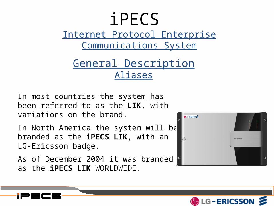
General DescriptionAliases
In most countries the system has been referred to as the LIK, with variations on the brand.
In North America the system will be branded as the iPECS LIK, with an LG-Ericsson badge.
As of December 2004 it was branded as the iPECS LIK WORLDWIDE.
iPECS Internet Protocol Enterprise Communications System
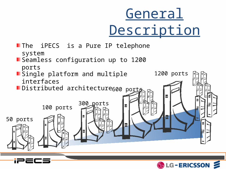
General Description
600 ports
300 ports
50 ports
Single platform and multiple interfaces
Seamless configuration up to 1200 ports
Distributed architecture
The iPECS is a Pure IP telephone system
100 ports
1200 ports
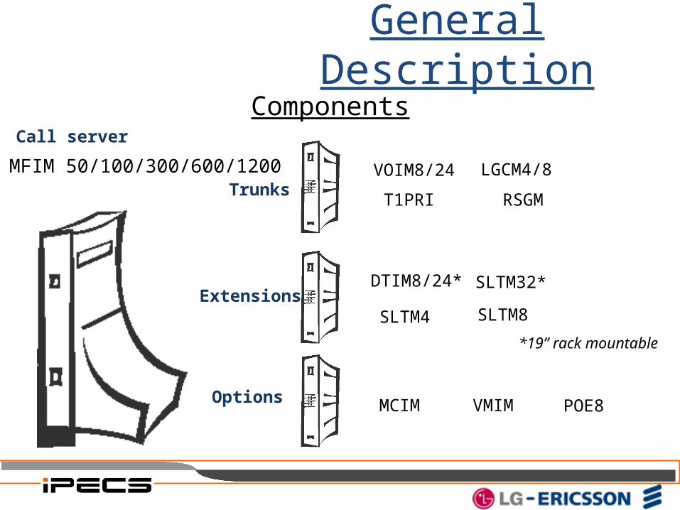
Components
VMIM
VOIM8/24
DTIM8/24*
SLTM4
SLTM32*
MCIM POE8
SLTM8
T1PRI
LGCM4/8
RSGMTrunks
Extensions
Options
MFIM 50/100/300/600/1200
Call server
*19” rack mountable
General Description
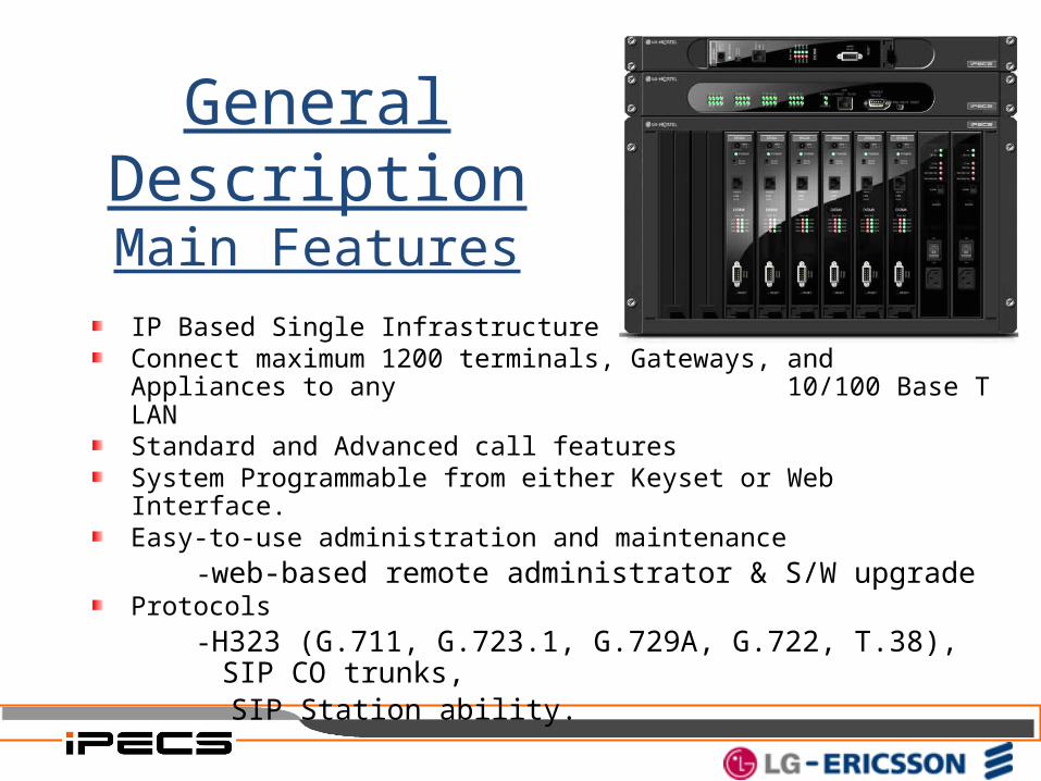
IP Based Single InfrastructureConnect maximum 1200 terminals, Gateways, and Appliances to any 10/100 Base T LANStandard and Advanced call featuresSystem Programmable from either Keyset or Web Interface.Easy-to-use administration and maintenance
-web-based remote administrator & S/W upgradeProtocols
-H323 (G.711, G.723.1, G.729A, G.722, T.38), SIP CO trunks, SIP Station ability.
General DescriptionMain Features
Scalability, Interoperability, Flexibility SME(Small to Medium sized Enterprise)Compatible with NetMeeting and other 3rd party applications supporting H.323 and CTI standardNetworking (large sized Enterprise : Max 1000 ports solution. )SIP CO trunk compatibleSMTP direct Email send capabilityCPU RedundancyT-NET capabilitySIP Station abilityLIP8xxx handset compatibilityProprietary PC/PDA based telephony ( Phontage)
General DescriptionMain Features
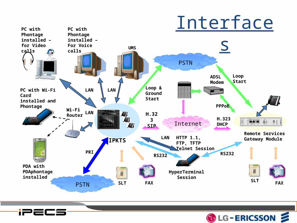
Interfaces
IPKTS
PSTN
Internet
PC with Phon-tage installed –for Video calls
Remote Services Gateway Module
SLT FAX
H.323SIP
PRI
H.323DHCP
SLT FAX
Loop Start
Loop & GroundStart
ADSLModem
PPPoE
HTTP 1.1,FTP, TFTPTelnet Session
HyperTerminalSession
RS232 RS232
PC with Phon-tage installed – For Voice calls
LAN
Wi-Fi Router
PDA with PDAphontage installed
PC with Wi-Fi Card installed and Phontage
LAN
LAN
LAN
PSTN
UMS
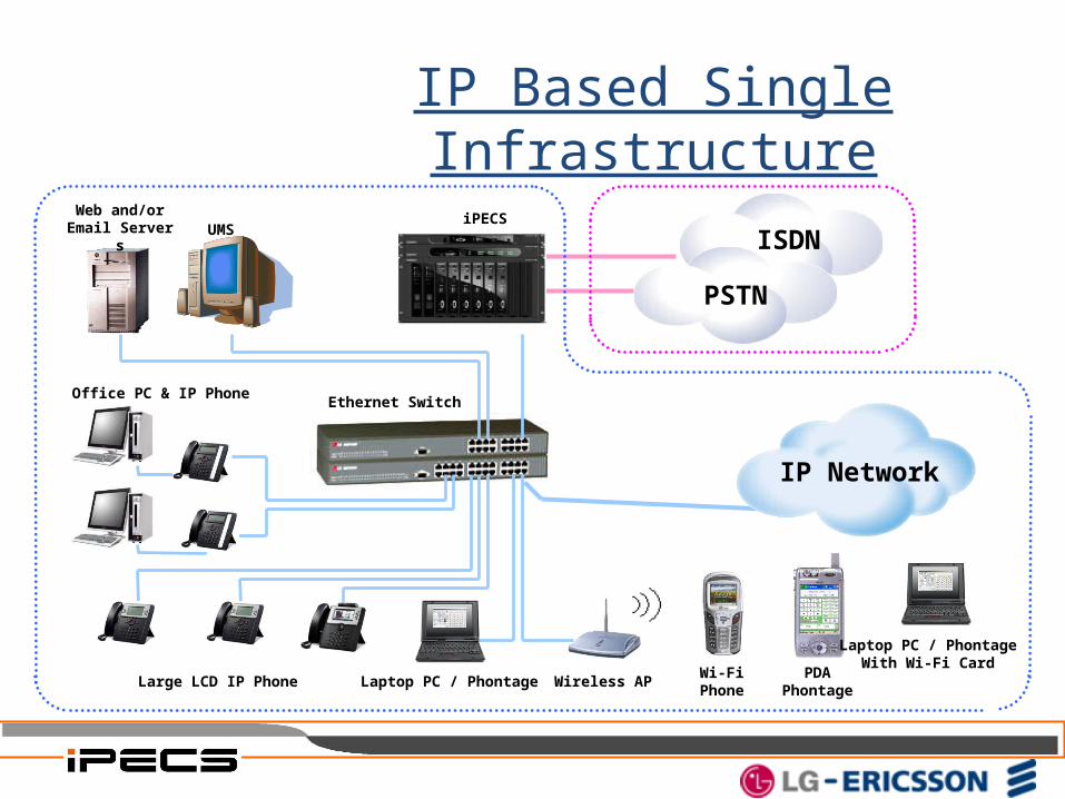
IP Based Single Infrastructure
PSTN
ISDNiPECS
Office PC & IP Phone
Wireless APWi-FiPhone
PDAPhontage
Ethernet Switch
Laptop PC / Phontage
Web and/or Email Server
s
Large LCD IP Phone
Laptop PC / PhontageWith Wi-Fi Card
UMS
IP Network
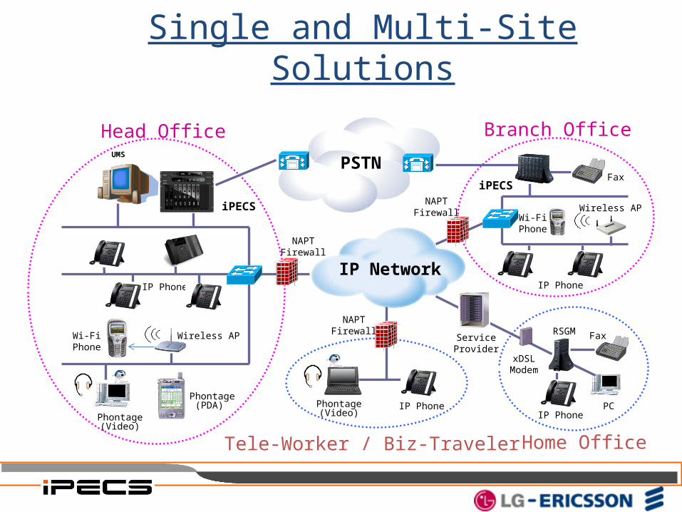
IP Network
PSTN
Head Office Branch Office
Home OfficeTele-Worker / Biz-Traveler
Wireless AP RSGM
Phontage(Video)
Phontage(PDA)
Wi-FiPhone
xDSLModem
ServiceProvider
Phontage(Video)
Wi-FiPhone
Wireless AP
IP Phone
IP Phone
Fax
Fax
IP Phone
IP Phone
iPECS
iPECS
NAPTFirewall
PC
NAPTFirewall
NAPTFirewall
Single and Multi-Site Solutions
UMS
Features in P3 MFIM(MFIME)Mobiles as an Extension ( Pseudo linked pairs)User WEB programming Access – Station and SystemACD Agent HelpACD CIQ Page AlertSupervisor Login/Logout – multiple groupsStation Call CoverageCO access without CO button at IP Key-PhoneSilent Text MessageRemote Call Forward
iPECS Phase 3 System Features
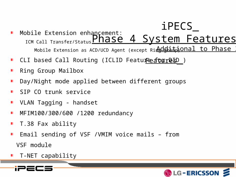
iPECS Phase 4 System Features Additional to Phase 3 Features Mobile Extension enhancement:
ICM Call Transfer/Status
Mobile Extension as ACD/UCD Agent (except Ring group)
CLI based Call Routing (ICLID Feature for DID )
Ring Group Mailbox
Day/Night mode applied between different groups
SIP CO trunk service
VLAN Tagging - handset
MFIM100/300/600 /1200 redundancy
T.38 Fax ability
Email sending of VSF /VMIM voice mails – from VSF module
T-NET capability
iPECS Phase 5 System Features
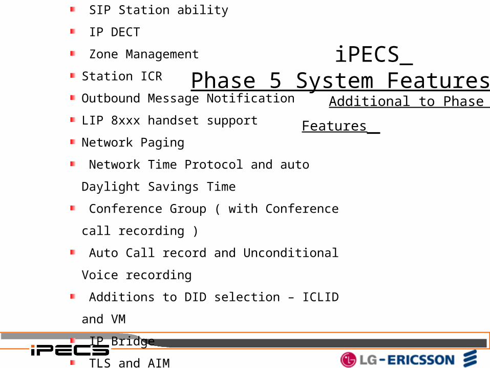
Additional to Phase 4 Features SIP Station ability
IP DECT
Zone Management
Station ICR
Outbound Message Notification
LIP 8xxx handset support
Network Paging
Network Time Protocol and auto Daylight Savings Time
Conference Group ( with Conference call recording )
Auto Call record and Unconditional Voice recording
Additions to DID selection – ICLID and VM
IP Bridge
TLS and AIM
Phase 5 Features• SIP CO trunk and SIP station ability
• Phase 5 has both SIP trunk and Station ability. Will support generic SIP handsets with basic call ability, or the LG LVP-2000 SIP Video Phone for SIP Video calls. Note that SIP support requires the use of a VOIM8 or VOIM 24 for IPSEC ability.
• T-Net• All Phase 5 systems ( including the iPECS 50) will support
Transparent NETworking, where one MFIM retains control over an entire group of systems. This enables central management and Local survivability with/of all the slave systems if the intersystem link fails. PSTN Failover is also a feature of T-NET.
• MFIM100/300/600/1200 Redundancy• Redundancy caters for customer sites where system downtime
due to MFIM failure, is of prime importance. This enables a second Slave MFIM to monitor the active MFIM until it fails – then seamlessly ( within approx 3 seconds ) become the Active MFIM. As from the Commercial release of phase 5 ALL MFIM’s ( except iPECS 50 ) will be available with the Redundancy option.

Phase 5 Features• Zone Management
• Allows Networked or remote site equipment to be grouped based upon that devices specific zone requirements. This means individual devices can be grouped to suit time and date, language (Nation code), or VSF module access.
• Outbound Message Notification• The VSF/VMIM are able to dial an external number to notify a user of a
new voice message. When a caller leaves a message with notification
configured, the system places a call to the registered mobile extension.
When the user answers, the extension prompt is played followed by the
new message prompt.
When the password is matched, the VSF/VMIM connects the external
called party to the VSF/VMIM mailbox and plays the main menu,
allowing the user to retrieve messages.
The system will retry the notification until the notification is successful
or the number of call attempts reaches the Retry count.
Phase 5 Features• Station ICR (Individual call routing)
• Allows each station to forward calls based upon Caller ID or time base. Each Station can have up to 10 separate Scenarios.
• Network Paging• Allows a page made from one site to be heard at another networked
site, including T-NET sites.
• TLS (Transport Layer Security)• Allows encryption of data. This can slow response times.
• Web Phone• Allows basic IP phone functions (ID and password protected) by
downloading Active X from the MFIM. (Key code required)
• System and Station Administration Via Web Page
• Off Line Web Admin
• NTP and DST• Network Time Protocol and Daylight Savings Time are able to be
Automatically updated/adjusted. (NTP server must be available)

Phase 5 Features• Conference Group
• Allows an Active conference group to be setup – i.e. invites to join the conference are sent to members. Requires an MCIM, allows up to 32 simultaneous members. This is initiated by the attendant.
• Conference Call Recording
• Allows the above conference group call to be recorded in either the VSF, the UMS or an external Voice mail system.
• IP Bridge
• Allows calls to be transferred between Master and Slave stations. • Additions to DID selection
• ICLID and VM routing now also available as in dial choices with DID calls.
• AIM interface
• Unconditional Call Recording to VM/Phontage.
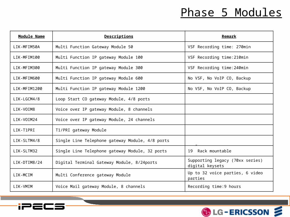
Phase 5 Modules
Module Name Descriptions Remark
LIK-MFIM50A Multi Function Gateway Module 50 VSF Recording time: 270min
LIK-MFIM100 Multi Function IP gateway Module 100 VSF Recording time:210min
LIK-MFIM300 Multi Function IP gateway Module 300 VSF Recording time:240min
LIK-MFIM600 Multi Function IP gateway Module 600 No VSF, No VoIP CO, Backup
LIK-MFIM1200 Multi Function IP gateway Module 1200 No VSF, No VoIP CO, Backup
LIK-LGCM4/8 Loop Start CO gateway Module, 4/8 ports
LIK-VOIM8 Voice over IP gateway Module, 8 channels
LIK-VOIM24 Voice over IP gateway Module, 24 channels
LIK-T1PRI T1/PRI gateway Module
LIK-SLTM4/8 Single Line Telephone gateway Module, 4/8 ports
LIK-SLTM32 Single Line Telephone gateway Module, 32 ports 19” Rack mountable
LIK-DTIM8/24 Digital Terminal Gateway Module, 8/24ports Supporting legacy (70xx series) digital keysets
LIK-MCIM Multi Conference gateway Module Up to 32 voice parties, 6 video parties
LIK-VMIM Voice Mail gateway Module, 8 channels Recording time:9 hours
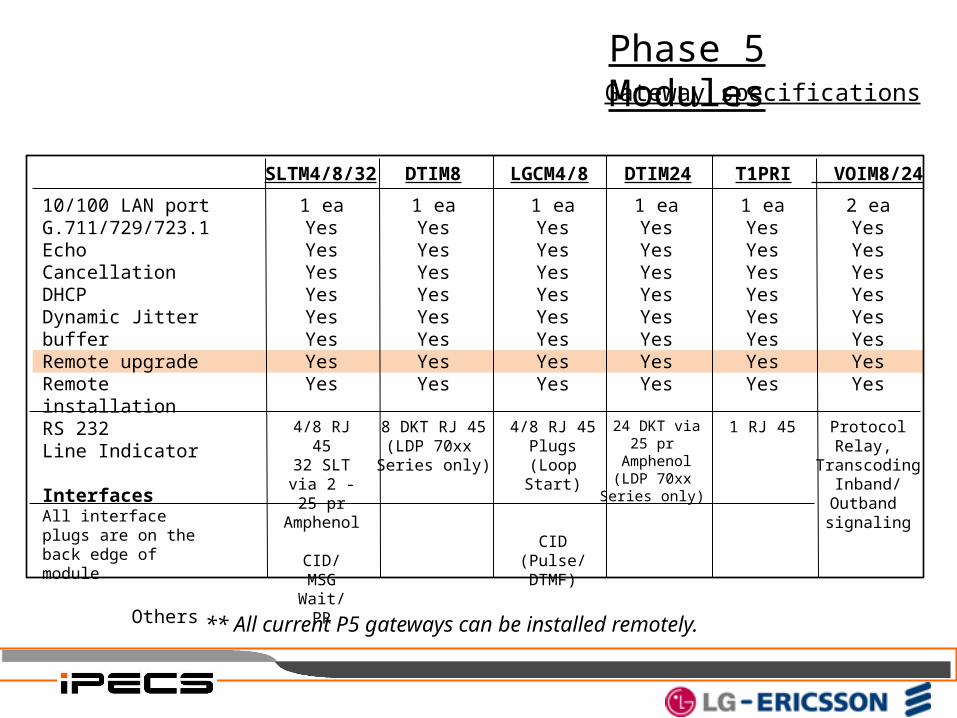
SLTM4/8/32 DTIM8 T1PRILGCM4/8 DTIM24 VOIM8/24
10/100 LAN portG.711/729/723.1Echo CancellationDHCPDynamic Jitter bufferRemote upgradeRemote installationRS 232Line Indicator
Interfaces All interface plugs are on the back edge of module Oth-ers
1 eaYesYesYesYesYesYesYesYes
4/8 RJ 4532 SLT via 2 - 25 pr
Amphenol CID/
MSG Wait/PR
1 eaYesYesYesYesYesYesYesYes
8 DKT RJ 45(LDP 70xx Series only)
1 eaYesYesYesYesYesYesYesYes
4/8 RJ 45Plugs
(Loop Start)
CID(Pulse/DTMF)
1 eaYesYesYesYesYesYesYesYes
24 DKT via25 pr
Amphenol(LDP 70xx
Series only)
1 eaYesYesYesYesYesYesYesYes
1 RJ 45
2 eaYesYesYesYesYesYesYesYes
ProtocolRelay,
TranscodingInband/
Outband signaling
** All current P5 gateways can be installed remotely.
Gateway specifications
Phase 5 Modules
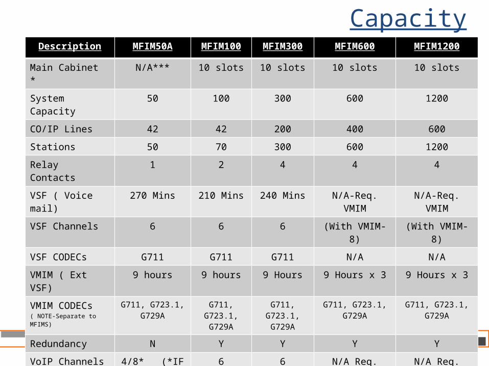
CapacityDescription MFIM50A MFIM100 MFIM300 MFIM600 MFIM1200
Main Cabinet * N/A*** 10 slots 10 slots 10 slots 10 slots
System Capacity 50 100 300 600 1200
CO/IP Lines 42 42 200 400 600
Stations 50 70 300 600 1200
Relay Contacts 1 2 4 4 4
VSF ( Voice mail) 270 Mins 210 Mins 240 Mins N/A-Req. VMIM N/A-Req. VMIM
VSF Channels 6 6 6 (With VMIM-8) (With VMIM-8)
VSF CODECs G711 G711 G711 N/A N/A
VMIM ( Ext VSF) 9 hours 9 hours 9 Hours 9 Hours x 3 9 Hours x 3
VMIM CODECs ( NOTE-Separate to MFIMS)
G711, G723.1,G729A
G711, G723.1,G729A
G711, G723.1,G729A
G711, G723.1,G729A
G711, G723.1,G729A
Redundancy N Y Y Y Y
VoIP Channels 4/8* (*IF G711) 6 6 N/A Req. VoIMx N/A Req. VoIMx
USB Host Port 1 port 1 port 1 port 1 port 1 port
Max RSGMs ** 16 35 98 300 600
Attendants 4 4 5 5 5

CapacityDescription MFIM50A MFIM100 MFIM300 MFIM600 MFIM1200
Serial Port 1 1 1 1 1
Music source I/P 1 2 2 2 2
Ext. Control Relays 1 2 4 4 4
Alarm/Doorbell I/P 1 2 2 2 2
Ext. Page Zones 2 2 2 2 2
Int. page Zones 10 10 35 35 100
Dss Consoles per Station 9 /2 2 9 9 9
CO Line Groups 20 20 72 72 200
Station & Hunt Groups 40 40 48 48 100
Stn & Hnt Grp Members 50 70 70 70 200
Exec/Sec Pairs 10 10 36 36 100
SMDR Buffer 5000 5000 10000 15000 30000
System Speed Dial 800(48 digits) 800(48 digits) 3000(48digits) 6000(48dgts) 12000(48dgts)
Station Speed dial 20(48 dgts) 20(48 dgts) 100(48 dgts) 100(48 dgts) 100(48 dgts)
Last number redial 10 10 10 10 10
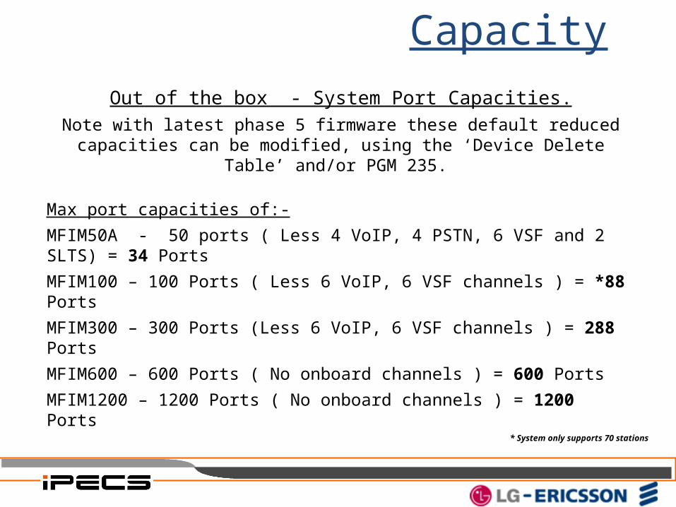
Capacity
Out of the box - System Port Capacities.
Note with latest phase 5 firmware these default reduced capacities can be modified, using the ‘Device Delete Table’ and/or PGM 235.
Max port capacities of:-
MFIM50A - 50 ports ( Less 4 VoIP, 4 PSTN, 6 VSF and 2 SLTS) = 34 Ports
MFIM100 – 100 Ports ( Less 6 VoIP, 6 VSF channels ) = *88 Ports
MFIM300 – 300 Ports (Less 6 VoIP, 6 VSF channels ) = 288 Ports
MFIM600 – 600 Ports ( No onboard channels ) = 600 Ports
MFIM1200 – 1200 Ports ( No onboard channels ) = 1200 Ports
* System only supports 70 stations
END of Section


![iPECS CMdownload.ortemir.kiev.ua/EricssonLG/iPECS/CM/ELGE_iPECS... · 2018. 9. 3. · iPECS-CM Installation Manual Issue 1.2 [EU] European Union Declarations of Conformity Ericsson-LG](https://img.dokumen.tips/doc/110x75/6122db4eda2bba43a876244e/ipecs-2018-9-3-ipecs-cm-installation-manual-issue-12-eu-european-union-declarations.jpg)