Embed Size (px)
Citation preview

KT-05.3
IP-Stile
Assembly &
Operation Manual
IP-Stile
KТ-05.3
Assembly and Operation Manual

Assembly and Operation Manual
2
CONTENTS1. APPLICATION ..................................................................................................3 2. OPERATION CONDITIONS..............................................................................3 3. TECHNICAL SPECIFICATIONS.......................................................................3 4. STANDARD DELIVERY SET............................................................................4 5. OPTIONAL EQUIPMENT SUPPLIED ON REQUEST ......................................4 6. DESIGN AND OPERATION..............................................................................5
6.1 Main features ..............................................................................................5 6.2 Design.........................................................................................................5 6.3 Control devices ...........................................................................................9 6.4 INPUT CONTROL SIGNALS AND THEIR PARAMETERS AT AUTONOMOUS CONTROL..10 6.5 THE KT-05.3 IP-STILE STAND-ALONE OPERATION...........................................12 6.6 OPERATION AS PART OF AN ACS...................................................................12 6.7 OPTIONAL EXTERNAL DEVICES* .....................................................................13 6.8 IP MODE AND IP DEFAULT JUMPERS .........................................................13
7 MARKING AND PACKAGING........................................................................14 8 SAFETY REQUIREMENTS.............................................................................14
8.1 INSTALLATION SAFETY REQUIREMENTS ...........................................................14 8.2 OPERATION SAFETY REQUIREMENTS ..............................................................14
9 INSTALLATION INSTRUCTIONS ..................................................................15 9.1 INSTALLATION DETAILS..................................................................................15 9.2 INSTALLATION TOOLS....................................................................................15 9.3 CABLE LENGTH ............................................................................................16 9.4 INSTALLATION PROCEDURE ...........................................................................16
10 OPERATION ...................................................................................................19 10.1 GENERAL RECOMMENDATIONS ......................................................................19 10.2 POWER-UP ..................................................................................................19 10.3 STAND-ALONE OPERATING MODES .................................................................19 10.4 TROUBLESHOOTING......................................................................................21
11 ACTIONS IN EMERGENCY CASES ..............................................................23 11.1 EMERGENCY EXIT BY USE OF ANTI-PANIC BARRIER ARMS..................................23 11.2 MECHANICAL UNLOCKING..............................................................................24
12 MAINTENANCE ..............................................................................................24 13 TRANSPORTATION AND STORAGE............................................................26 APPENDIX А .........................................................................................................27 APPENDIX B.........................................................................................................29 APPENDIX C.........................................................................................................31
KT-05.3 IP-Stile
3
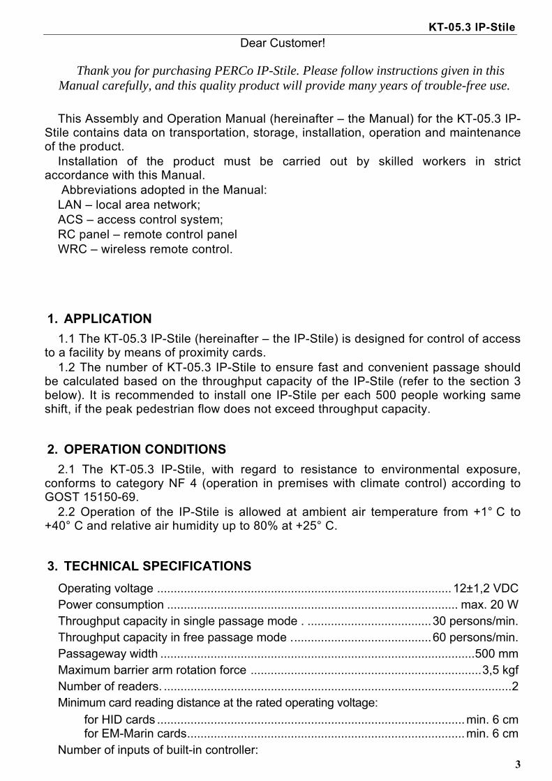
Dear Customer!
Thank you for purchasing PERCo IP-Stile. Please follow instructions given in this Manual carefully, and this quality product will provide many years of trouble-free use.
This Assembly and Operation Manual (hereinafter – the Manual) for the KT-05.3 IP-
Stile contains data on transportation, storage, installation, operation and maintenance of the product.
Installation of the product must be carried out by skilled workers in strict accordance with this Manual.
Abbreviations adopted in the Manual: LAN – local area network; ACS – access control system; RC panel – remote control panel WRC – wireless remote control.
1. APPLICATION
1.1 The КТ-05.3 IP-Stile (hereinafter – the IP-Stile) is designed for control of access to a facility by means of proximity cards.
1.2 The number of KT-05.3 IP-Stile to ensure fast and convenient passage should be calculated based on the throughput capacity of the IP-Stile (refer to the section 3 below). It is recommended to install one IP-Stile per each 500 people working same shift, if the peak pedestrian flow does not exceed throughput capacity.
2. OPERATION CONDITIONS
2.1 The KT-05.3 IP-Stile, with regard to resistance to environmental exposure, conforms to category NF 4 (operation in premises with climate control) according to GOST 15150-69.
2.2 Operation of the IP-Stile is allowed at ambient air temperature from +1° C to +40° C and relative air humidity up to 80% at +25° C.
3. TECHNICAL SPECIFICATIONS
Operating voltage ........................................................................................ 12±1,2 VDC Power consumption ....................................................................................... max. 20 W Throughput capacity in single passage mode . .....................................30 persons/min. Throughput capacity in free passage mode ..........................................60 persons/min. Passageway width ..............................................................................................500 mm Maximum barrier arm rotation force .....................................................................3,5 kgf Number of readers. ........................................................................................................2 Minimum card reading distance at the rated operating voltage:
for HID cards ............................................................................................min. 6 cm for EM-Marin cards...................................................................................min. 6 cm
Number of inputs of built-in controller:
Assembly and Operation Manual
4
Remote control.......................................................................................................3 Testing. ..................................................................................................................2
Number of relay outputs of the built-in controller: (relay outputs NC, С and NO). ...............................................................................2
Communication interface standard .............................................. Ethernet (IEEE 802.3) Number of users (access cards) ..................................................................up to 50 000 Events memory capacity ............................................................................up to 135 000 RC panel cable length1 ...................................................................................min. 6,6 m RC panel overall dimensions (L х W х H) ................................................120х84х20 mm Weight of the RC panel ................................................................................ max. 0,2 kg Ingress protection rating ............................................................... IP41 under EN 60529 Electric shock protection class...................................... III under GOST R IEC 335-1-94 Mean time to failure..................................................................... no less than 1 500 000 Mean lifetime........................................................................................................8 years Overall dimensions with barrier arms (LxWxH) .............................. 1050х684х1030 mm Maximum net weight ...............................................................................................70 kg
4. STANDARD DELIVERY SET
The KT-05.3 IP-Stile housing ....................................................................................1 Barrier arm. ................................................................................................................3 (itemized separately in the price list, type chosen by the Customer at the time of order) Key to housing top cover lock. ...................................................................................2 Mechanical release key. ............................................................................................2 Key to blank cover lock . ............................................................................................2 RC panel with a cable, min. 6,6 m. ............................................................................1 Jumper. ......................................................................................................................2
Mounting hardware: self-adhesive cable tie mount ....................................................................................3 nylon cable tie, 100 mm ........................................................................................6
Spare parts spring. ...................................................................................................................2
Software: PERCo-SL01 Single-user software (СD). .............................................................1
Technical documentation: Assembly and operation manual. ..........................................................................1 Certificate .............................................................................................................1 User guide. ...........................................................................................................1 PERCo-SL01operation manual. ............................................................................1
Package: Transportation box. ...............................................................................................1
5. OPTIONAL EQUIPMENT SUPPLIED ON REQUEST
System time panel PERCo-AU05……………………………………………………. 1
1 Maximum allowable length of the RC panel cable is 30 m

KT-05.3 IP-Stile
5
Wireless remote control………………………………………………………………… 1 Intrusion detector and siren…………………………………………………………… 1
Note – technical specifications of optional devices are given in corresponding documentation to the same devices.
6. DESIGN AND OPERATION
6.1 Main features
The KT-05.3 IP-Stile can be operated either as a stand-alone unit from the remote control panel or wireless remote control, as a part of an ACS by means of the proximity card readers, or by a PC connected to a LAN through Ethernet (IEEE 802.3).
The IP-Stile is operated with safe supply voltage – maximum 14 V. The IP-Stile has low power consumption not exceeding 20 W. At power isolation the IP-Stile retains the status set at the moment of the shutoff
for both passage directions: locked if this direction was locked at the moment of the shutoff; or open if the direction was open before the shutoff.
A resetting mechanism ensures automatic reset of barrier arms to home position after each passage.
Smooth and quiet operation of the IP-Stile is ensured by a damper. To ensure correct register of passages the resetting mechanism has built-in optic
rotation sensors. The built-in mechanical release lock ensures safe emergency unlocking with a
key providing free rotation of the barrier arms. Installed in a line several KT-05.3 IP-Stiles form a secured passageway without
installation of extra guide barriers. Front covers of the IP-Stile housing have mnemonic indicators of proximity card
readers installed under the front covers.
6.2 Design
6.2.1 The KT-05.3 IP-Stile design is shown in Figure 1. Numbers of the items hereinafter refer to the item numbers as shown in Figure 1 unless stated otherwise.
Assembly and Operation Manual
6
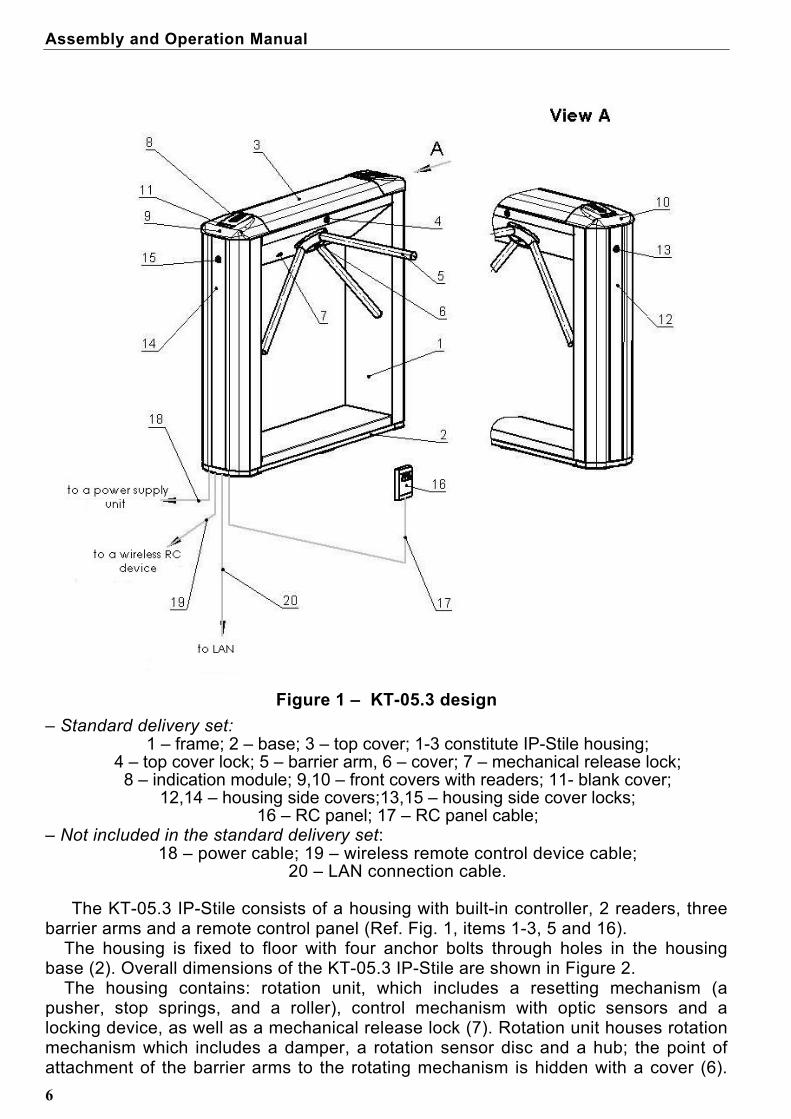
Figure 1 – KT-05.3 design
– Standard delivery set: 1 – frame; 2 – base; 3 – top cover; 1-3 constitute IP-Stile housing;
4 – top cover lock; 5 – barrier arm, 6 – cover; 7 – mechanical release lock; 8 – indication module; 9,10 – front covers with readers; 11- blank cover;
12,14 – housing side covers;13,15 – housing side cover locks; 16 – RC panel; 17 – RC panel cable;
– Not included in the standard delivery set: 18 – power cable; 19 – wireless remote control device cable;
20 – LAN connection cable.
The KT-05.3 IP-Stile consists of a housing with built-in controller, 2 readers, three barrier arms and a remote control panel (Ref. Fig. 1, items 1-3, 5 and 16).
The housing is fixed to floor with four anchor bolts through holes in the housing base (2). Overall dimensions of the KT-05.3 IP-Stile are shown in Figure 2.
The housing contains: rotation unit, which includes a resetting mechanism (a pusher, stop springs, and a roller), control mechanism with optic sensors and a locking device, as well as a mechanical release lock (7). Rotation unit houses rotation mechanism which includes a damper, a rotation sensor disc and a hub; the point of attachment of the barrier arms to the rotating mechanism is hidden with a cover (6).
KT-05.3 IP-Stile
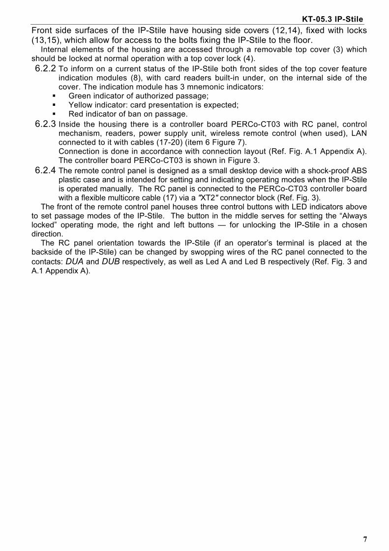
Front side surfaces of the IP-Stile have housing side covers (12,14), fixed with locks (13,15), which allow for access to the bolts fixing the IP-Stile to the floor.
7
Internal elements of the housing are accessed through a removable top cover (3) which should be locked at normal operation with a top cover lock (4). 6.2.2 To inform on a current status of the IP-Stile both front sides of the top cover feature
indication modules (8), with card readers built-in under, on the internal side of the cover. The indication module has 3 mnemonic indicators: Green indicator of authorized passage; Yellow indicator: card presentation is expected; Red indicator of ban on passage.
6.2.3 Inside the housing there is a controller board PERCo-CT03 with RC panel, control mechanism, readers, power supply unit, wireless remote control (when used), LAN connected to it with cables (17-20) (item 6 Figure 7). Connection is done in accordance with connection layout (Ref. Fig. A.1 Appendix A). The controller board PERCo-CT03 is shown in Figure 3.
6.2.4 The remote control panel is designed as a small desktop device with a shock-proof ABS plastic case and is intended for setting and indicating operating modes when the IP-Stile is operated manually. The RC panel is connected to the PERCo-CT03 controller board with a flexible multicore cable (17) via a "ХТ2" connector block (Ref. Fig. 3).
The front of the remote control panel houses three control buttons with LED indicators above to set passage modes of the IP-Stile. The button in the middle serves for setting the “Always locked” operating mode, the right and left buttons — for unlocking the IP-Stile in a chosen direction.
The RC panel orientation towards the IP-Stile (if an operator’s terminal is placed at the backside of the IP-Stile) can be changed by swopping wires of the RC panel connected to the contacts: DUA and DUB respectively, as well as Led A and Led B respectively (Ref. Fig. 3 and A.1 Appendix A).

Assembly and Operation Manual
8
Figure 2 – Overall dimensions of the KT-05.3
6.2.5 The PERCo-CT03 (Figure 3) controller board houses:
- connector «X2» (Control) to connect the control mechanism (connected to the “X1” connector of the control mechanism with the turnstile cable);
- connector block «XT1» (In) to connect additional inputs; - connector block «XT2» to connect the RC panel /the wireless remote control; - connector block «XT3» to connect proximity card readers; - connector block «XT4» (+12VDC) to connect power supply; - connector block «XT7» (Out) to connect additional outputs; - connector S1 to connect LAN over Ethernet (IEEE 802.3); - connectors ХР1 and ХР3.1 - ХР3.3 to install jumpers.
6.2.6 The KT-05.3 IP-Stile is powered via a power cable (18). As power supply it is recommended to use 12 VDC power supply with linear stabilization of voltage and pulsation amplitude at output not exceeding 50 mV.

KT-05.3 IP-Stile
9
Figure 3 – PERCo-CТ03 controller board
6.3 Control devices
6.3.1 The KT-05.3 IP-Stile can be operated as follows: 6.3.1.1 As a stand-alone unit: – from the RC panel; – from wireless remote control; The mentioned devices can be connected to the IP-Stile: – any device alone; – both simultaneously (in parallel).
Note – At parallel connection of the above devices to the IP-Stile superposition of the control signals from them may occur. In that case the IP-Stile response will conform to response to the obtained combination of input signals (Ref. Appendix B).

Assembly and Operation Manual
6.3.1.2
10
As an element of an ACS controlled: – from readers (at presentation of access cards); – from a PC with connection to LAN over Ethernet (IEEE 802.3).
Note – If the KT-05.3 IP-Stile receives control commands from stand-alone devices and ACS simultaneously, a higher priority command will be executed. Priority of commands in descending order: by reader – by PC – by stand-alone device.
6.3.2 Devices mentioned in the Clause 6.3.1.1 are connected with cables (17) and (19) to corresponding connector blocks «XT2» and «XT4» of the controller board PERCo-CT03 (Figure 3) in accordance with connection layout (Figure А.1 Appendix А).
6.3.3 The RC panel is connected to contacts GND, DUA, DUSt, DUB, Led A, Led St, Led B and Buzzer of the connector block «XT2».
6.3.4 Wireless remote control is connected to DUA, DUSt and DUB of the connector block «XT2». Power supply of the wireless remote control is connected to the contact +12V of the connector block «XT4».
6.3.5 To receive signals from additional equipment its outputs are connected to contacts GND, In1 and In2 of the connector block «XT1».
6.3.6 Additional equipment is controlled at connection to contacts NO3(4), C3(4), NC3(4) of the connector block «XT7».
6.3.7 Symbols of the connector blocks on the PERCo-CT03 board and designation of their contacts are shown in Figure 3 and a label similar to Figure А.1, Appendix А, placed on the top cover(3).
6.4 Input control signals and their parameters at autonomous control
6.4.1 The microcontroller on the PERCo-CT03 board processes incoming commands
(monitors the status of the contacts DUA, DUSt and DUB), follows signals from the optic rotation sensors and generates consequent commands for the control mechanism, as well as signals for the remote control panel indication (Led A, Led DUSt and Led B).
6.4.2 The KT-05.3 IP-Stile is operated by input of a low-level signal relative to the «GND» contact at the contacts DUA, DUSt and DUB of the connector block “XT2” while either a normally open relay contact or a circuit with open-collector output can be used as the control element. (Ref. Fig. 4).

KT-05.3 IP-Stile
11
a)
b)
Figure 4 – Control elements of the wireless remote control device (WRC):
a – a normally open relay contact; b – a circuit with open-collector output;
Note – 2-KOHm resistors wired to a power supply bus + 3.3 V are used as a mean of
high-level signal generation at all the input contacts (DUA, DUSt and DUB).
6.4.3 Parameters of all input and output signals are detailed in Appendix C.2 and C.3.
Assembly and Operation Manual
6.5
12
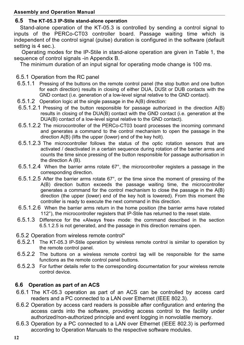
The KT-05.3 IP-Stile stand-alone operation Stand-alone operation of the KT-05.3 is controlled by sending a control signal to
inputs of the PERCo-CT03 controller board. Passage waiting time which is independent of the control signal (pulse) duration is configured in the software (default setting is 4 sec.).
Operating modes for the IP-Stile in stand-alone operation are given in Table 1, the sequence of control signals -in Appendix B.
The minimum duration of an input signal for operating mode change is 100 ms.
6.5.1 Operation from the RC panel 6.5.1.1 Pressing of the buttons on the remote control panel (the stop button and one button
for each direction) results in closing of either DUA, DUSt or DUB contacts with the GND contact (i.e. generation of a low-level signal relative to the GND contact).
6.5.1.2 Operation logic at the single passage in the А(В) direction: 6.5.1.2.1 Pressing of the button responsible for passage authorized in the direction А(В)
results in closing of the DUA(В) contact with the GND contact (i.e. generation at the DUA(В) contact of a low-level signal relative to the GND contact).
6.5.1.2.2 The microcontroller of the PERCo-CT03 board processes the incoming command and generates a command to the control mechanism to open the passage in the direction A(В) (lifts the upper (lower) end of the key holt).
6.5.1.2.3 The microcontroller follows the status of the optic rotation sensors that are activated / deactivated in a certain sequence during rotation of the barrier arms and counts the time since pressing of the button responsible for passage authorisation in the direction А (В).
6.5.1.2.4 When the barrier arms rotate 67°, the microcontroller registers a passage in the corresponding direction.
6.5.1.2.5 After the barrier arms rotate 67°, or the time since the moment of pressing of the А(В) direction button exceeds the passage waiting time, the microcontroller generates a command for the control mechanism to close the passage in the А(В) direction (the upper (lower) end of the key holt is lowered). From this moment the controller is ready to execute the next command in this direction.
6.5.1.2.6 When the barrier arms return in the home position (the barrier arms have rotated 112°), the microcontroller registers that IP-Stile has returned to the reset state.
6.5.1.3 Difference for the «Always free» mode: the command described in the section 6.5.1.2.5 is not generated, and the passage in this direction remains open.
6.5.2 Operation from wireless remote control* 6.5.2.1 The KT-05.3 IP-Stile operation by wireless remote control is similar to operation by
the remote control panel. 6.5.2.2 The buttons on a wireless remote control tag will be responsible for the same
functions as the remote control panel buttons. 6.5.2.3 For further details refer to the corresponding documentation for your wireless remote
control device.
6.6 Operation as part of an ACS 6.6.1 The KT-05.3 operation as part of an ACS can be controlled by access card
readers and a PC connected to a LAN over Ethernet (IEEE 802.3). 6.6.2 Operation by access card readers is possible after configuration and entering the
access cards into the software, providing access control to the facility under authorized/non-authorized principle and event logging in nonvolatile memory.
6.6.3 Operation by a PC connected to a LAN over Ethernet (IEEE 802.3) is performed according to Operation Manuals to the respective software modules.

KT-05.3 IP-Stile
13
6.7 Optional external devices* 6.7.1 The KT-05.3 IP-Stile can optionally be equipped with system time panel PERCo-
AU05, intrusion detector and siren. 6.7.2 Connection of system time panel PERCo-AU05 is performed in accordance with
installation manual for it. 6.7.3 The intrusion detector is connected to the connector block “XT1”, to input №2
(contacts In2 and GND) while siren to the connector block “XT7”, to output №4 (contacts NO4 and C4) on the PERCo-CT03 board (location of the connector blocks is shown in Figure 3). Connection layout of an intrusion detector and siren are shown in Appendix A, Figure A.1.
Attention! Installation of the intrusion detector on the KT-05.3 housing must be carried out only at the manufacturer's works.
6.8 IP MODE and IP DEFAULT jumpers Jumpers at connector ХР1 (location of the connector is shown in Figure 3.1):
position 1 – 2 – jumper IP MODE, position 2 – 3 – jumper IP DEFAULT. At IP DEFAULT position of a jumper after power-on the controller will operate with
default settings of its IP-address, the gateway IP-address and the subnet mask. At IP DEFAULT position of a jumper the controller will clear the access password to
this controller. User settings of an IP-address, a gateway IP-address, a subnet mask, if they had been set, will be saved and at next power-on if the IP DEFAULT jumper is not installed the controller will start operating with old settings. If the IP DEFAULT jumper is removed and an IP-address, a gateway IP-address, a subnet mask were changed, the controller will operate with new settings (without power switch-off), breaking off all current connections with default settings (if any connections were active).
For operation in networks with dynamic assignment of IP-addresses IP MODE jumper should be installed. When the power is on if user settings of an IP-address, a gateway IP-address and a subnet mask were set, the controller will try to operate with them (request from the dhcp server these settings). If not or in case of impossibility to operate with previous settings (denial of the dhcp-server to prolong the settings), the controller will receive new settings from a dhcp-server, new settings of an IP-address, a gateway IP-address, a subnet mask, will start to operate with them and save as User settings.
* This equipment is not included in the standard delivery set.
Assembly and Operation Manual
14
7 MARKING AND PACKAGING
7.1 The IP-Stile has a marking sticker on the internal side of the top cover and a label – inside, on the rear side of the housing. To get access to the marking sticker and the label, open the top cover (3).
To do so proceed as follows: Switch off power supply of the IP-Stile; Insert the key into the top cover lock (4); Turn the key clockwise till it stops (open the lock, the lock cylinder will move out
together with a lock bolt at this); Holding the front edge of the top cover (3) carefully lift it and turning it remove it from
the turnstile housing. Be careful not to damage the controller board located under the cover while removing the top cover;
Place the top cover on a flat steady surface. Installation of the top cover back into its operation position is carried out in reverse order.
After mounting the top cover, lock the top cover lock by pushing lock cylinder into its case till it clicks. Turn on the IP-Stile power supply.
7.2 To protect the IP-Stile against damage during transportation and storage the IP-Stile as standard (Ref. Section 4.1) is packed in a transportation box, 1210х400х1100 mm, weight brutto– 88 kg.
8 SAFETY REQUIREMENTS
8.1 Installation safety requirements
8.1.1 The installation should be carried out only by qualified personnel after careful study of this Manual with observance of general safety rules.
8.1.2 During installation works: – All works should be performed only after the power supply is switched off and dis-
connected from the AC mains; – Only serviceable tools should be used for installation; – During installation before the housing is fixed to the floor be careful not to drop it; – Before first power-up of the IP-Stile make sure installation and all connections are
done properly. 8.1.3 Installation of a power supply unit must be performed with observance of safety
requirements mentioned in its certificate.
8.2 Operation safety requirements
8.2.1 Observe general electrical safety rules when operating the IP-Stile. – Do not use the IP-Stile under conditions that do not comply with the re-
quirements of Section 2 of this Manual. – Do not use the IP-Stile at supply voltage that does not comply with the
requirements of Section 3 of the Manual.
8.2.2 Power supply unit must be operated with observance of safety requirements men-tioned in its certificate.
KT-05.3 IP-Stile
9 INSTALLATION INSTRUCTIONS
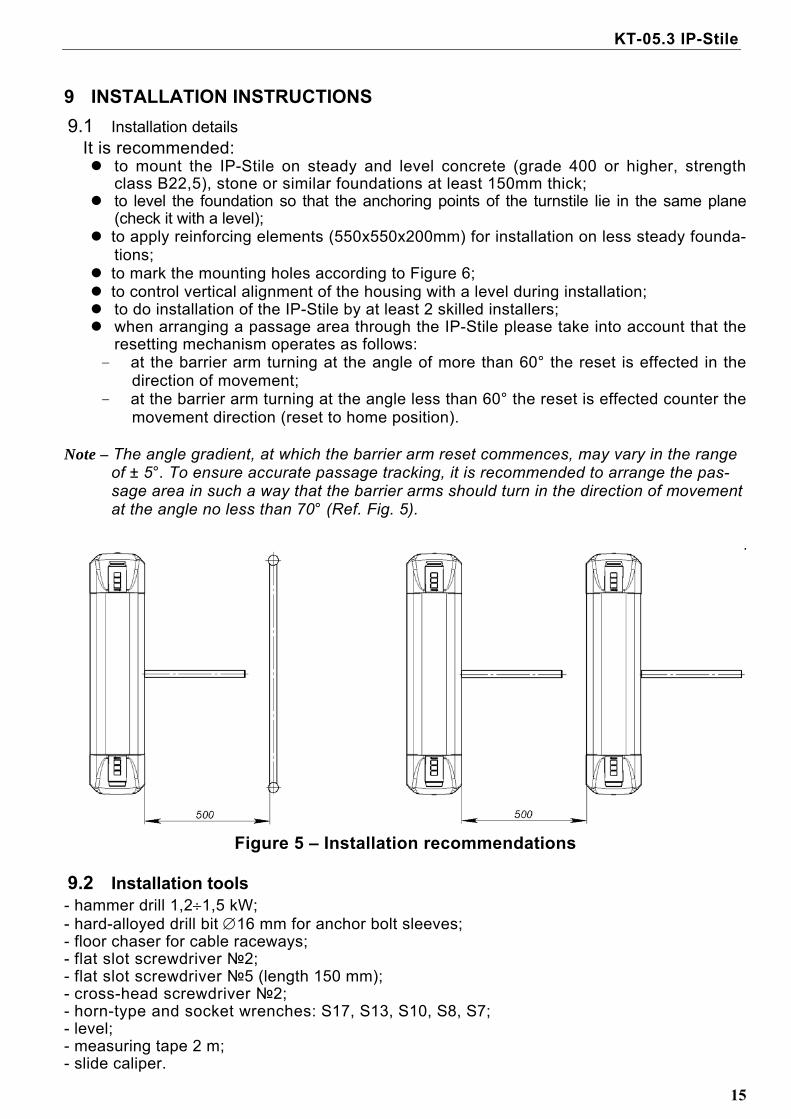
9.1 Installation details It is recommended: to mount the IP-Stile on steady and level concrete (grade 400 or higher, strength
class B22,5), stone or similar foundations at least 150mm thick; to level the foundation so that the anchoring points of the turnstile lie in the same plane
(check it with a level); to apply reinforcing elements (550х550х200mm) for installation on less steady founda-
tions; to mark the mounting holes according to Figure 6; to control vertical alignment of the housing with a level during installation; to do installation of the IP-Stile by at least 2 skilled installers; when arranging a passage area through the IP-Stile please take into account that the
resetting mechanism operates as follows: - at the barrier arm turning at the angle of more than 60° the reset is effected in the
direction of movement; - at the barrier arm turning at the angle less than 60° the reset is effected counter the
movement direction (reset to home position). Note – The angle gradient, at which the barrier arm reset commences, may vary in the range
of ± 5°. To ensure accurate passage tracking, it is recommended to arrange the pas-sage area in such a way that the barrier arms should turn in the direction of movement at the angle no less than 70° (Ref. Fig. 5).
Figure 5 – Installation recommendations
9.2 Installation tools - hammer drill 1,21,5 kW; - hard-alloyed drill bit 16 mm for anchor bolt sleeves; - floor chaser for cable raceways; - flat slot screwdriver №2; - flat slot screwdriver №5 (length 150 mm); - cross-head screwdriver №2; - horn-type and socket wrenches: S17, S13, S10, S8, S7; - level; - measuring tape 2 m; - slide caliper.
15

Assembly and Operation Manual
Note – It is allowed to use other testing equipment and measuring tools provided the equipment in use ensures the required parameters and measurement accuracy.
9.3 Cable length The maximum allowed length of the remote control panel / wireless remote control cable is 30m. The maximum allowed length of the turnstile power cable depends on the cable cross-section and should not exceed: for cable with 0.75mm2 cross – section (AWG 18) —10 m; for cable with 1.5mm2 cross – section (AWG 16) —30 m.
9.4 Installation procedure Note! The manufacturer shall not be liable for any damage caused as the result of
improper installation and declines any claims arising thereof in case if the installation is done not in compliance with the instructions provided in this Manual. 9.4.1 Unpack the KT-05.3 IP-Stile and check the completeness as per product certificate. 9.4.2 Make holes for anchor bolt sleeves for the IP-Stile housing installation (Ref. Fig. 6).
Prepare a cable raceway for cables when cables are laid concealed under floor. Install and fix the turnstile housing only after all cables inside the turnstile housing and in electric raceways are laid. Cable routing inside the turnstile housing is shown in Figure 7.
Figure 6 – Installation layout
9.4.3 Insert anchor bolts sleeves into the holes so that they did not stick out above the floor surface. Remove the housing side covers (12, 14) by unlocking the locks (13, 15). Set up the housing on anchor bolt sleeves and fix it with the M10 bolts.
9.4.4 Install a power supply unit in its place (See power supply unit certificate for installa-tion procedure of the power supply unit).
9.4.5 Open the housing top cover (3) by opening it with a key (4 refer to section 6). 9.4.6 Connect the power cable (18) to the connector block “XT4” on the PERCo-CT03
board (Fig.3). Connect the cable (17) of the remote control panel (16) to the connec-tor block “XT2” on the PERCo-CT03 board. If necessary, connect cables of other de-vices to the corresponding connector blocks of the PERCo-CT03 board (Ref. Fig. 3 and Figure А.1 of Appendix А).
9.4.7 Check the accuracy, reliability and safety of all electrical connections. Fix all the ca-bles using the self-adhesive cable tie mounts and nylon cable ties included in the de-livery set. After connecting all the cables and anchoring the housing to the floor, re-turn the top cover (3) (Ref. Section 6) and housing side covers (12,14) in their operat-ing position in order reverse to dismantling.
16

KT-05.3 IP-Stile
9.4.8
17
For installation of the barrier arms into operational position, first unscrew the М4х25 bolt and take the cover (6) off the rotation mechanism. Unscrew the М8х30 bolts on the barrier arms (5). Install the barrier arm into the corresponding slots and fix it using the bolts with spring washers. Make sure the bolts are tightened enough to provide secure no-play fixing of the barrier arm. Repeat this sequence to install other barrier arms.
9.4.9 Carry out a test power-up of the IP-Stile according to the section 9. When the installa-tion is completed, the IP-Stile is ready for operation.

Assembly and Operation Manual
18
Figure 7 – Cable routing inside the IP-Stile housing:
1 – power cable; 2 – cable from the RC panel/wireless remote control device; 3 – LAN cable connection via Ethernet (IEEE 802.3);
4 – turnstile cable; 5 – readers connection cables; 6 –PERCo-CT03 board; 7 – control mechanism;
KT-05.3 IP-Stile
19
10 OPERATION
10.1 General recommendations
1) Observe general electrical safety requirements while operating the IP-Stile.
2) Do not connect the power supply of the IP-Stile to the mains with voltage and frequency rating other than specified in the Power supply certificate.
3) Do not use substances for cleaning the IP-Stile that may cause mechanical damage or corrosion of the surfaces.
4) Do not move through the IP-Stile passage area any objects with dimensions exceeding the width of the passageway.
5) Do not jerk and hit any elements of the IP-Stile so as to prevent their mechanical deformation.
6) Do not dismantle or adjust mechanisms ensuring operation of the IP-Stile.
10.2 Power-up Make sure all connections are correct (Ref. Sections 9.4.6-9.4.7). Make sure the
barrier arms are in the home position (the passageway is blocked with a barrier arm). Make sure the mechanical release lock is closed (the IP-Stile is mechanically locked, Ref. Section 11.2).
Connect the power supply to the mains with electric parameters as per its documentation.
Turn the power on. Yellow indicators (middle ones) of the indication modules are on and the red indicator above the middle button on the RC panel is on.
10.3 Stand-alone operating modes Setting of the operating modes by the remote control panel and the corresponding
indication is detailed in Table 1. Please kindly note that: - the passage directions are independent of each other, i.e. setting an operating
mode in one direction will not change an already set operating mode in another; - the "Single passage in the set direction” operating mode can be changed for the
free passage in the same direction or the "Always locked" mode; - the "Free passage in the set direction" can only be changed for the "Always
locked" mode.
Assembly and Operation Manual
20
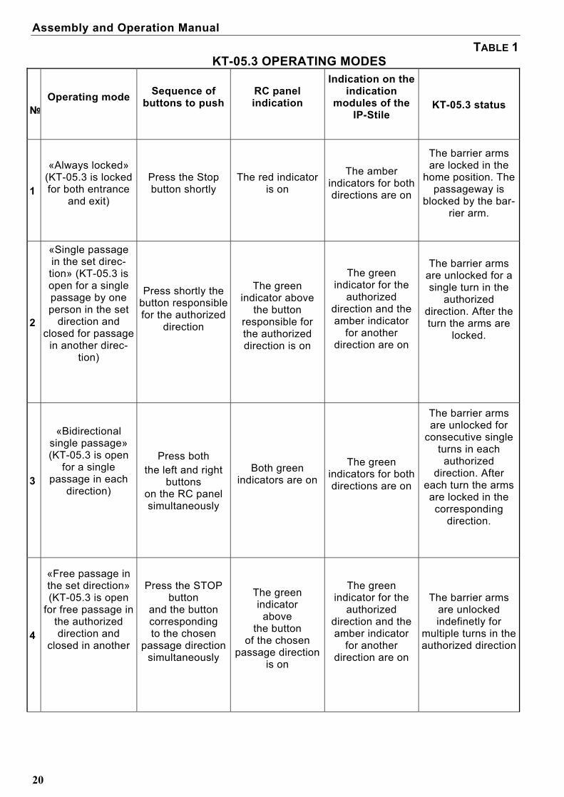
TABLE 1 KT-05.3 OPERATING MODES
№
Operating mode
Sequence of buttons to push
RC panel indication
Indication on the indication
modules of the IP-Stile
KT-05.3 status
1
«Always locked» (KT-05.3 is locked for both entrance
and exit)
Press the Stop button shortly
The red indicator is on
The amber indicators for both directions are on
The barrier arms are locked in the
home position. The passageway is
blocked by the bar-rier arm.
2
«Single passage in the set direc-tion» (KT-05.3 is open for a single passage by one person in the set
direction and closed for passage
in another direc-tion)
Press shortly the button responsible for the authorized
direction
The green indicator above
the button responsible for the authorized direction is on
The green indicator for the
authorized direction and the amber indicator
for another direction are on
The barrier arms
are unlocked for a single turn in the
authorized direction. After the turn the arms are
locked.
3
«Bidirectional single passage» (KT-05.3 is open
for a single passage in each
direction)
Press both the left and right
buttons on the RC panel simultaneously
Both green indicators are on
The green indicators for both directions are on
The barrier arms are unlocked for
consecutive single turns in each
authorized direction. After
each turn the arms are locked in the corresponding
direction.
4
«Free passage in the set direction» (KT-05.3 is open
for free passage in the authorized direction and
closed in another
Press the STOP button
and the button corresponding to the chosen
passage direction simultaneously
The green indicator
above the button
of the chosen passage direction
is on
The green indicator for the
authorized direction and the amber indicator
for another direction are on
The barrier arms are unlocked indefinetly for
multiple turns in the authorized direction

KT-05.3 IP-Stile
21
5
«Free passage in the set direction
and a single passage in the
opposite direction»
(KT-05.3 is open for free passage in
the authorized direction and a
single passage in another)
Press shortly the Stop button
together with the button responsible
for the free passage direction;
then press the button responsible
for the other direction
Both green indicators are on
The green indicators for both directions are on
The barrier arms are unlocked indefinitely for
multiple turns in the free passage
direction and a single turn in the single passage
direction
6
«Free passage in both directions» (KT-05.3 is open
for free passage in both directions)
Press shortly the three buttons
together
Both green indicators are on
The green indicators for both directions are on
The barrier arms are unlocked indefinitely for
multiple turns in both directions
Note – Pressing a button on the remote control panel results in sending a low-level signal relative to the GND contact to the corresponding contacts on the connector block “XT2” (DUA, DUB and DUSt).
When the power is switched on, the KT-05.3 reset state is locked (provided that the mechanical release lock (7) is locked).
In the single passage mode the KT-05.3 IP-Stile will be locked as soon as a single passage in the authorized direction is completed. If the passage is not completed within the passage waiting time preset by the software during the configuration (default setting is 4 sec.), the IP-Stile will be automatically locked even if the passage has not occurred. When passage is authorized in both directions, after one passage is completed, the passage waiting time countdown for another direction starts.
When an access card not entered in the list is presented, the red indicator on the side
of the presentation goes on for 2 seconds, the audio signal sounds, the KT-05.3 IP-Stile is not unlocked.
10.4 Troubleshooting Possible faults to be corrected by the customer themselves are given below.
Contact the manufacturer if other fault or malfunction occurs. Possible faults:
10.4.1 The controller is operating stand-alone but is not recognised by the software
This fault can occur as a result of the following causes: 1. No network settings in the PC – set an IP-address and a subnet mask in the PC
(the IP-Stile controller should be connected directly to the network card connector of the PC or to the equipment of the same computer (Hub, Switch).

Assembly and Operation Manual
22
2. A wrong password entered to this controller. Enter the right controller password into the software.
3. Faults related to the PC (software, data bases, etc.). Determine the fault by running the command ping 10.х.х.х (where 10.х.х.х is IP-
address of the controller). If this command runs without errors, the fault must be either in the software or in the network settings (faulty settings of the gateways). How to sort out such faults is partly given in Appendix C.
4. Faults related to LAN equipment between the PC and the controller (the
hub, the switch and other network apparatus including the communication cables).
Such faults can be determined by running the command ping 10.х.х.х (where
10.х.х.х is IP-address of the controller). If this command fails, the fault must relate to either the network settings or the connecting LAN apparatus including the communication cables, or to the controller (refer to the next section). How to sort out such faults is partly given in Appendix C.
5. Faults related to the controller (malfunction of the elements providing
connection through the Ethernet interface (IEEE 802.3)). To determine this fault, observe operation of two indicators near the LAN
connection point (to do so remove the cover off the KT-05.3 IP-Stile):

KT-05.3 IP-Stile
23
LINK – connection evidence (the green indicator on – the controller recognises
the LAN connection, the green indicator is off – the controller does not recognise the LAN connection);
АСТ – data exchange evidence (the red indicator blinking – the controller
recognises data exchange through the LAN, the red indicator off – the controller does not recognise data exchange through the LAN).
If the controller does not recognise the LAN connection, connect it to the cable of
another controller or a PC. If the controller still does not recognise the LAN connection, the controller is faulty and must be sent for repair.
10.4.2 The controller is not working
Remove the top cover (3) as described in section 6 of this Manual to get access to the controller for testing.
Testing of the relay outputs is assisted by test LEDs beside each of the relays. Activation / release of the relay is evident by the LEDs going on/ off.
Possible causes of the controller malfunction are as follows:
Loose cable fixing in the connector blocks on the controller board – tighten the cable fix-ing bolt with a screwdriver.
Faulty power supply of the controller – make sure the power supply is functional. Faulty controller connection lines of other devices (readers, the KT-05.3 housing, remote
control panel, wireless remote control, siren, etc.) – make sure the connection lines are operable.
Malfunction of the devices connected to the controller – make sure the connected de-vices are faultless.
Faulty radio components on the controller board – the controller needs repair at the manufacturer's site.
11 ACTIONS IN EMERGENCY CASES
For a fast safe escape from facilities in case of fire, natural disaster or other emergen-cies, an emergency exit is often required.
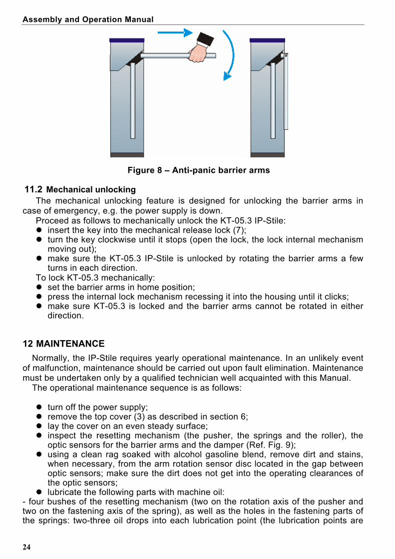
11.1 Emergency exit by use of anti-panic barrier arms
An additional emergency exit can be arranged by means of anti-panic barrier arms. Design of anti-panic barrier arms enables to ensure a free escape passage without any special means or tools.
To make the passageway free, just pull the horizontal barrier arm along its axis outwards the hub until released, then fold the arm down (Ref. Fig. 8).
Assembly and Operation Manual
24
Figure 8 – Anti-panic barrier arms
11.2 Mechanical unlocking The mechanical unlocking feature is designed for unlocking the barrier arms in
case of emergency, e.g. the power supply is down. Proceed as follows to mechanically unlock the KT-05.3 IP-Stile: insert the key into the mechanical release lock (7); turn the key clockwise until it stops (open the lock, thе lock internal mechanism
moving out); make sure the KT-05.3 IP-Stile is unlocked by rotating the barrier arms a few
turns in each direction. To lock KT-05.3 mechanically: set the barrier arms in home position; press the internal lock mechanism recessing it into the housing until it clicks; make sure KT-05.3 is locked and the barrier arms cannot be rotated in either
direction.
12 MAINTENANCE
Normally, the IP-Stile requires yearly operational maintenance. In an unlikely event of malfunction, maintenance should be carried out upon fault elimination. Maintenance must be undertaken only by a qualified technician well acquainted with this Manual.
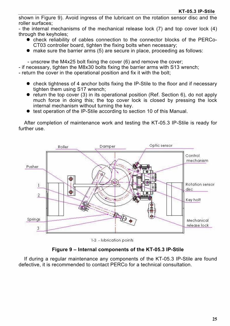
The operational maintenance sequence is as follows: turn off the power supply; remove the top cover (3) as described in section 6; lay the cover on an even steady surface; inspect the resetting mechanism (the pusher, the springs and the roller), the
optic sensors for the barrier arms and the damper (Ref. Fig. 9); using a clean rag soaked with alcohol gasoline blend, remove dirt and stains,
when necessary, from the arm rotation sensor disc located in the gap between optic sensors; make sure the dirt does not get into the operating clearances of the optic sensors;
lubricate the following parts with machine oil: - four bushes of the resetting mechanism (two on the rotation axis of the pusher and two on the fastening axis of the spring), as well as the holes in the fastening parts of the springs: two-three oil drops into each lubrication point (the lubrication points are
KT-05.3 IP-Stile
shown in Figure 9). Avoid ingress of the lubricant on the rotation sensor disc and the roller surfaces; - thе internal mechanisms of the mechanical release lock (7) and top cover lock (4) through the keyholes; check reliability of cables connection to the connector blocks of the PERCo-
CT03 controller board, tighten the fixing bolts when necessary; make sure the barrier arms (5) are secure in place, proceeding as follows:
- unscrew the М4х25 bolt fixing the cover (6) and remove the cover; - if necessary, tighten the М8х30 bolts fixing the barrier arms with S13 wrench; - return the cover in the operational position and fix it with the bolt; check tightness of 4 anchor bolts fixing the IP-Stile to the floor and if necessary
tighten them using S17 wrench; return the top cover (3) in its operational position (Ref. Section 6), do not apply
much force in doing this; the top cover lock is closed by pressing the lock internal mechanism without turning the key.
test operation of the IP-Stile according to section 10 of this Manual. After completion of maintenance work and testing the KT-05.3 IP-Stile is ready for
further use.
Figure 9 – Internal components of the KT-05.3 IP-Stile
If during a regular maintenance any components of the KT-05.3 IP-Stile are found defective, it is recommended to contact PERCo for a technical consultation.
25

Assembly and Operation Manual
26
13 TRANSPORTATION AND STORAGE
13.1 The KT-05.3 IP-Stile in the original package should be transported in closed freight containers or other closed type cargo transport units.
13.2 During storage and transportation the boxes can be stacked no more than 2 layers high.
13.3 Storage of the IP-Stile is allowed indoors at ambient temperature from – 25° C to + 40° C and relative air humidity up to 98% at +25° С.
13.4 After transportation or storage at temperatures below zero or in high air humidity, prior to the installation the IP-Stile must be kept unpacked for no less than 24 hours indoors in the climate conditions as per given in section 2).
KT-05.3 IP-Stile
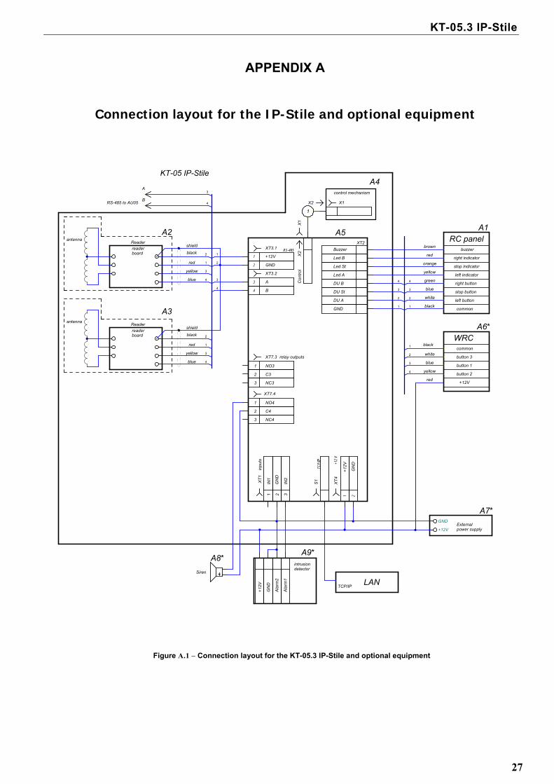
APPENDIX А
Connection layout for the IP-Stile and optional equipment
B
2
3
3
A
4
3
1
4
2
1
4
4
3
1
2
3
2
1
1
B
A
X2
X1
1
TCP/
IP
+12
V
+12
V
GN
D
1
2
3
4
red
red
3
2
Con
tro
l
XT
4
black
1
NC3
3
relay outputs
XT2
4
3
2
1
+12V
button 2
button 1
button 3
common
blue
yellow
red
black
shield
blue
shield
red
A8*
GN
D
+12
V
IN1
inpu
ts
C4
NC4
NO4
NO3
4
3IN
2
RS-485
S1
GND1
2
3
4
black
white
blue
green
blue
white
brown
orange
common
right button
stop button
left button
left indicator
buzzer
right indicator
stop indicatoryellow
XT
1
C3
Ala
rm1
yellow
yellow
black
WRC
2
antenna
Reader
Siren
2
XT7.3
+12V
control mechanism
A3
readerboard
Reader
antenna
readerboard
A9*intrusiondetector
XT7.4
XT3.2
GND
+12V
XT3.1
1
TCP/IP
GND
DU A
DU St
DU B
Led A
Led B
Buzzer
Led St
A4
A6*
A1A2
RS-485 to AU05
Ala
rm2
GN
D
X2
2
LAN
X1
A5
A7*
1
Externalpower supply
KT-05 IP-Stile
RC panel
Figure А.1 – Connection layout for the KT-05.3 IP-Stile and optional equipment
27
Assembly and Operation Manual
28
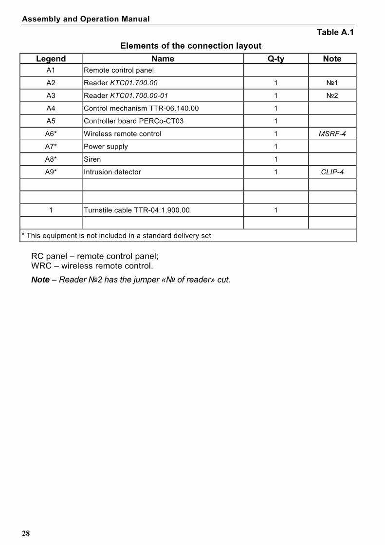
Table А.1
Elements of the connection layout
Legend Name Q-ty Note A1 Remote control panel
А2 Reader KTC01.700.00 1 №1
A3 Reader KTC01.700.00-01 1 №2
A4 Control mechanism TTR-06.140.00 1
A5 Controller board PERCo-CT03 1
A6* Wireless remote control 1 MSRF-4
A7* Power supply 1
A8* Siren 1
А9* Intrusion detector 1 CLIP-4
1 Turnstile cable TTR-04.1.900.00 1
* This equipment is not included in a standard delivery set
RC panel – remote control panel; WRC – wireless remote control.
Note – Reader №2 has the jumper «№ of reader» cut.

KT-05.3 IP-Stile
29
APPENDIX B
Algorithm of control signals generation during stand-alone operation
Input of a low-level signal relative to the «GND» contact at the contacts DUA, DUSt and DUB of the connector block “XT2” can generate the following commands:
Note: 1. The command is the falling edge of the signal at any of the contacts while the
corresponding signal levels are present at the other contacts. 2. The falling edge of the signal – when the signal level changes from high to low. Always locked (The KT-05.3 IP-Stile is locked for both entry and exit) - the falling edge at the contact DUSt with the high signal level at the contacts DUA
and DUB. This command closes both directions. Single passage in the direction А (The IP-Stile is open for passage of one
person in the direction А) – the falling edge at the contact DUA with the high signal level at the contacts
DUSt, DUB. This command opens the direction A either for the passage waiting time or until the
passage in this direction is completed, or until the «Always locked» command is given, while the direction В mode remains unchanged. The command is ignored if at the moment of its receipt the direction А is in the «Free passage» mode.
Single passage in the direction B (The IP-Stile is open for passage of one
person in the direction В) – the falling edge at the contact DUB with the high signal level at the contacts
DUSt, DUA. This command opens the direction В either for the passage waiting time or until the
passage in this direction is completed, or until the «Always locked» command is given, while the direction А mode remains unchanged. The command is ignored if at the moment of its receipt the direction В is in the «Free passage» mode.
Bidirectional single passage (The IP-Stile is open for one passage in each
direction) – the falling edge at the contact DUA with the low signal level at the contact DUB
and high level at the contact DUSt – or the falling edge at the contact DUB with the low signal level at the contact DUA
and high level at the contact DUSt. This command opens both directions, each for the passage waiting time or until the
passage in this direction is completed, or until the «Always locked» command is
Assembly and Operation Manual
given. The command is ignored for the direction which at the moment of its receipt is in the «Free passage» mode.
30
Free passage in the direction А (The IP-Stile is open for free passage in the direction A)
– the falling edge at the contact DUA with the low signal level at the contact DUSt and high level at the contact DUB,
– or the falling edge at the contact DUSt with the low signal level at the contact DUA and high level at the contact DUB.
This command opens the direction А until until the the command «Always locked» is given, while the direction В remains unchanged.
Free passage in the direction В (The IP-Stile is open for free passage in the
direction В) – the falling edge at the contact DUB with the low signal level at the contact DUSt
and the high signal level DUA. – or the falling edge at the contact DUSt with the low signal level at the contact
DUB and high level at the contact DUA. This command opens the direction В until the the command «Always locked» is
given while the direction А remains unchanged. Free passage (The IP-Stile is open for free passage in both directions) – the falling edge at the contact DUA with the low signal level at the contacts DUB,
DUSt, – or the falling edge at the contact DUB with the low signal level at the contacts
DUA, DUSt, – or the falling edge at the contact DUSt with the low signal level at the contacts
DUA, DUB. This command opens both directions until the the command «Always locked» is
given.
Note – For the remote control panel: the falling edge — the moment the corresponding RC panel button is being pressed; the low signal level— the corresponding RC panel button is pressed. the high signal level— the corresponding RC panel button is not pressed.
KT-05.3 IP-Stile
31
APPENDIX C
C.1 General information on the built-in controller PERCo-CT03 The controller provides:
- connection with the PC and other controllers over the Ethernet (IEEE 802.3) in-terface;
- support of the protocol stack TCP/IP (ARP, IP, ICMP, TCP, UDP, DHCP); - support of the system communication protocol (application layer); - the possibility of program memory update via the Ethernet;
At the production stage the controller is assigned a unique physical address (MAC-address) and IP-address (given in the label of the processor microchip), the subnet mask (255.0.0.0) and IP-address of the gateway (0.0.0.0).
IP-address of the controller (and, if necessary, IP-address of the gateway and the subnet mask) within a system can be changed at the configuration stage by one of two means: using the DHCP protocol or manually by the system administrator. Con-figuration mode is chosen by installation of the jumper on the controller board (Ref. Section 6.8 of the Manual). The controller features nonvolatile memory to store information on up to 50 000 cards and 135 000 events. The controller PERCo-CT03 features nonvolatile RTC-timer (real-time clock). The controller PERCo-CT03 operates with card readers PERCo-KTC01.700.00 via RS-485. The controller enables connection of the remote control panel:
- the controller features 3 inputs for passage control through the IP-Stile: DUA, DUSt, DUB.
- the controller features 4 outputs for control of the remote control panel indica-tion: Buzzer, Led A, Led St, Led B.
For connection to the local Ethernet the controller has the connector RJ45 featuring two indicators:
LINK – connection evidence (green, ON/OFF); АСТ – data exchange evidence (red, ON/OFF).
The controller, as an ACS element, provides the following Operating Modes: «Open»; «Control»; «Closed».
The controller provides status control of 2 inputs controlled by dry contacts or OK, performing the following functions:
- In1, In2 – input of additional equipment. The controller ensures control of 2 relay outputs Out3 and Out4 (outputs of relays NC, С and NO) (are used as an Alarm output and output of additional equipment connec-tion):
C.2 Parameters of input signals DS1(2), IN1(2), DUA(B) and DUSt

Assembly and Operation Manual
32
All unconnected inputs are pulled to a power supply. 2-KOHm resistors wired to a power supply bus + 3.3 V are used as means of high-level signal generation at all the input contacts (DS1(2), In1(2), DUA(B) and DUSt).
Activation evidence of the signals DS1(2) and In1(2) depends on description of their condition:
If an input is assigned as “normally open” its activation is done then by means of a low-level signal relative to the «GND» sent to it. A normally open relay contact or a circuit with open-collector output can be used as the control element.
If an input is assigned as “normally closed” its activation is done by withdrawing of a low-level signal relative to the «GND» from it. A normally closed relay contact or a circuit with open-collector output can be used as the control element.
The initial condition of DUA (B) and DUSt signals is not assigned and is deemed as
“normally open” for that reason activation of these inputs is done by means of a low-level signal relative to the «GND» sent to them. A normally open relay contact or a circuit with open-collector output can be used as the control element.
Control element has to provide for the following characteristics of signals:
– Control element – relay contact;
– Minimal commutated current – no more than 1 mA
– Resistance of a closed contact (with connection cable resistance taken into account) – no more than 300 ohm
– Control element – circuit with open-collector output: voltage at a closed contact (a low-level signal, at the input of the controller), – no more than 0,8 V.
C.3 Parameters of output signals for relay outputs Relay outputs Out3 and Out4 having complete group of contacts (normally open NO,
normally closed NC and common output C contact) can be used to control CO, 3O and optional equipment as well as to transmit alarm to Central Surveillance Desk and have the following parameters:
– Maximum commutated voltage, DC – no more than 30 V
– Maximum commutated voltage, AC – no more than 42 V
– Maximum commutated DC/AC for outputs Out – no more than 2 A
– Closed contact resistance – no more than 0,15 ohm

PERCo Industrial
Tel.: +7 812 3216172, +7 812 3298924 Fax: +7 812 2923608
Legal address:
123-V ul. Leona Pozemskogo, Pskov, 180600, Russia
e-mail: [email protected]
www.percoweb.com

www.perco.ru