Embed Size (px)
Citation preview
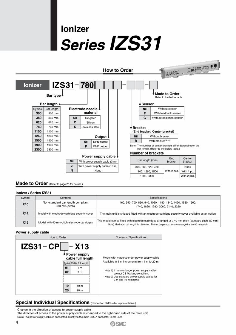
How to Order
Ionizer
Series IZS31
Symbol
300380620780
11001260150019002300
Bar length
300 mm
380 mm
620 mm
780 mm
1100 mm
1260 mm
1500 mm
1900 mm
2300 mm
Bracket(End bracket, Center bracket)
Without bracket
With bracket Note)
Nil
B
Bar length (mm)
300, 380, 620, 780
1100, 1260, 1500
1900, 2300
Endbracket
With 2 pcs.
Centerbracket
None
With 1 pc.
With 2 pcs.
Number of brackets
Note) The number of center brackets differ depending on the bar length. (Refer to the below table.)
Made to Order (Refer to page 23 for details.)
Special Individual Specifications (Contact an SMC sales representative.)
780Ionizer
Bar type
Bar lengthElectrode needle
materialTungsten
Silicon
Stainless steel
Nil
CS
OutputNPN output
PNP output
Nil
P
Made to OrderRefer to the below table.
Without sensor
With feedback sensor
With autobalance sensor
Nil
FG
Sensor
Power supply cableWith power supply cable (3 m)
With power supply cable (10 m)
None
Nil
ZN
IZS31
· Change in the direction of access to power supply cable The direction of access to the power supply cable is changed to the right-hand side of the main unit.Note) The power supply cable is connected directly to the main unit. A connector is not used.
Symbol
X10460, 540, 700, 860, 940, 1020, 1180, 1340, 1420, 1580, 1660,
1740, 1820, 1980, 2060, 2140, 2220
SpecificationsContents
Non-standard bar length compliant(80 mm-pitch)
X14 The main unit is shipped fitted with an electrode cartridge security cover available as an option.Model with electrode cartridge security cover
X15This model comes fitted with electrode cartridges arranged at a 40 mm-pitch (standard pitch: 80 mm).
Note) Maximum bar length is 1260 mm. The air purge nozzles are arranged at an 80 mm-pitch.Model with 40 mm-pitch electrode cartridges
Ionizer / Series IZS31
How to Order Contents / Specifications
Model with made-to-order power supply cableAvailable in 1 m increments from 1 m to 20 m.
Note 1) 11 mm or longer power supply cablesare not CE Marking-compliant.
Note 2) Use standard power supply cables for3 m and 10 m lengths.
Power supply cable
Symbol
0102
1920
Cable full length
1 m
2 m
19 m
20 m
Power supplycable full length
IZS31 CP X13
4

Feedback sensor / IZS31-DF
Power supply cable· IZS31-CP (3 m)· IZS31-CPZ (10 m)
Bracket
End bracket / IZS31-BE Center bracket / IZS31-BM
Note) The model number is for a single bracket.
Electrode cartridge· IZS31-NT (Material: Tungsten)· IZS31-NC (Material: Silicon)· IZS31-NS (Material: Stainless steel)
Autobalance sensor / IZS31-DG
Note) The number of center brackets required, as listed below, depends on the bar length.Two end brackets are always required regardless of the bar length.
Bar length (mm)
300, 380, 620, 780
1100, 1260, 1500
1900, 2300
Quantity
End bracket
2 pcs.
Center bracket
None
With 1 pc.
With 2 pcs.
End bracket
Hexagon sockethead cap screw
M4 x 6
(Accessories)
Center bracket
Accessories
5
Ionizer Series IZS31
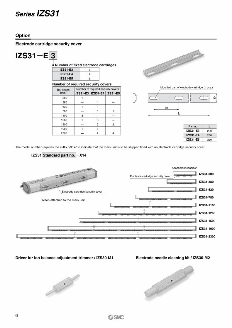
Driver for ion balance adjustment trimmer / IZS30-M1 Electrode needle cleaning kit / IZS30-M2
Attachment condition
The model number requires the suffix “-X14” to indicate that the main unit is to be shipped fitted with an electrode cartridge security cover.
IZS31-2300
IZS31-1900
IZS31-1500
IZS31-1260
IZS31-1100
IZS31-780
IZS31-620
IZS31-380
IZS31-300
Part no L200
280
360
IZS31-E3IZS31-E4IZS31-E5
IZS31 Standard part no. X14
30
L
80
Mounted part of electrode cartridge (n pcs.)
IZS31 E 3Number of fixed electrode cartridges
3
4
5
IZS31-E3IZS31-E4IZS31-E5
IZS31-E3Bar length
(mm)
300
380
620
780
1100
1260
1500
1900
2300
Number of required security covers
Number of required security covers
IZS31-E3 IZS31-E4 IZS31-E51
—
1
—
3
1
—
1
—
—
1
1
1
1
3
2
5
2
—
—
—
1
—
—
2
—
4
Electrode cartridge security cover
Electrode cartridge security cover
When attached to the main unit
Option
Electrode cartridge security cover
6
Series IZS31
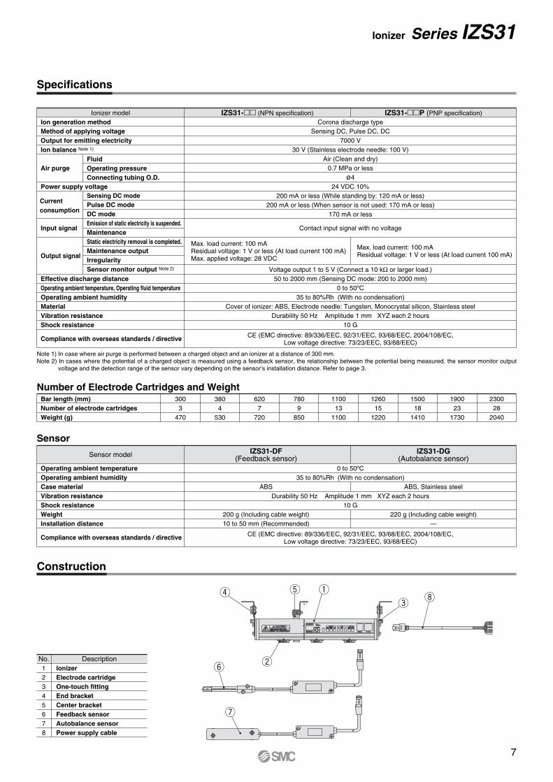
Specifications
Number of Electrode Cartridges and Weight
Sensor
Construction
Bar length (mm)Number of electrode cartridgesWeight (g)
Operating ambient temperature Operating ambient humidityCase material Vibration resistance Shock resistance WeightInstallation distance
Compliance with overseas standards / directive
0 to 50ºC35 to 80%Rh (With no condensation)
Durability 50 Hz Amplitude 1 mm XYZ each 2 hours10 G
ABS
200 g (Including cable weight)10 to 50 mm (Recommended)
CE (EMC directive: 89/336/EEC, 92/31/EEC, 93/68/EEC, 2004/108/EC,Low voltage directive: 73/23/EEC, 93/68/EEC)
ABS, Stainless steel
220 g (Including cable weight)—
3003
470
3804
530
6207
720
7809
850
110013
1100
126015
1220
150018
1410
190023
1730
230028
2040
Sensor model IZS31-DF(Feedback sensor)
IZS31-DG(Autobalance sensor)
12345678
DescriptionNo.Ionizer Electrode cartridge One-touch fittingEnd bracket Center bracketFeedback sensorAutobalance sensorPower supply cable
r t q
ei
u
wy
Note 1) In case where air purge is performed between a charged object and an ionizer at a distance of 300 mm.Note 2) In cases where the potential of a charged object is measured using a feedback sensor, the relationship between the potential being measured, the sensor monitor output
voltage and the detection range of the sensor vary depending on the sensor’s installation distance. Refer to page 3.
FluidOperating pressureConnecting tubing O.D.
Sensing DC modePulse DC modeDC modeEmission of static electricity is suspended.MaintenanceStatic electricity removal is completed.Maintenance outputIrregularitySensor monitor output Note 2)
IZS31-P (PNP specification)IZS31- (NPN specification)Corona discharge type
Sensing DC, Pulse DC, DC7000 V
30 V (Stainless electrode needle: 100 V)Air (Clean and dry)
0.7 MPa or lessø4
24 VDC 10%200 mA or less (While standing by: 120 mA or less)
200 mA or less (When sensor is not used: 170 mA or less)170 mA or less
Contact input signal with no voltage
Voltage output 1 to 5 V (Connect a 10 kΩ or larger load.)50 to 2000 mm (Sensing DC mode: 200 to 2000 mm)
0 to 50ºC35 to 80%Rh (With no condensation)
Cover of ionizer: ABS, Electrode needle: Tungsten, Monocrystal silicon, Stainless steelDurability 50 Hz Amplitude 1 mm XYZ each 2 hours
10 G
Ionizer model
CE (EMC directive: 89/336/EEC, 92/31/EEC, 93/68/EEC, 2004/108/EC,Low voltage directive: 73/23/EEC, 93/68/EEC)
Max. load current: 100 mAResidual voltage: 1 V or less (At load current 100 mA)Max. applied voltage: 28 VDC
Max. load current: 100 mAResidual voltage: 1 V or less (At load current 100 mA)
Ion generation methodMethod of applying voltageOutput for emitting electricityIon balance Note 1)
Air purge
Power supply voltage
Input signal
Output signal
Effective discharge distanceOperating ambient temperature, Operating fluid temperatureOperating ambient humidityMaterialVibration resistanceShock resistance
Compliance with overseas standards / directive
Current consumption
7
Ionizer Series IZS31
(2) Pulse DC modeAlternatively emits positive and negative ions.When an autobalance sensor is used, the ionizer automatically adjusts the ion balance to within 30 V. If the ion balance exceeds 30 V due to electrode needle contamination, the ionizer outputs a maintenance output signal.This mode is suited for removing spatial static electricity or preventing workpieces from becoming electrostatically charged.
When an autobalance sensor is used.Either “Manual Operation” or “Automatic Operation” can be selected as the operation method depending on the method of ion balance adjustment.
(3) DC modeContinuously emits positive and negative ions. Parts other than the object need to be appropriately grounded to prevent from being charged. This mode cannot emit both positive and negative ions at the same time.
When an autobalance sensor is not used.Use a balance adjustment trimmer to adjust the ion balance. This requires the separate use of a measuring instrument to verify the ion balance.
Energy savingrun
Continuousstatic electricityremoval run
Note) When the feedback sensor is installed at a height of 25 mm.
Even after the completion of static electricity removal, this method continues to remove static electricity using DC pulses while controlling the ion balance, so that the workpiece’s electrostatic potential falls within 30 V. For the removal of static electricity from nonconductive workpieces, “Continuous Static Electricity Removal Run” is recommended.
The ionizer stops discharging upon completion of static electricity removal. It resumes discharging when the workpiece’s electrostatic potential exceeds 30 V. Note)
For the removal of static electricity from conductive workpieces, “Energy Saving Run” is recommended.
Manual run
Automatic run This method continuously adjusts the ion balance. For the removal of static electricity from stationary workpieces or the removal of spatial static electricity, “Automatic Operation” is recommended.
When a maintenance start signal is input or the ionizer is turned on, this method adjusts the ion balance. For the removal of static electricity from moving workpieces, “Manual Operation” is recommended. Start system operation after the completion of ion balance adjustment.
1. Operation modeThere are 3 different operation modes (Sensing DC mode / Pulse DC mode / DC mode) for the IZS31, which can be selected based on the application and operating condition.
Series IZS31
Functions
(1) Sensing DC modeThe discharge time is reduced by detecting the workpiece’s charge condition with a feedback sensor which feeds the data back to the ionizer and causes ions with the polarity best suited for static electricity removal being emitted. The static electricity removal completion signal turns off when the workpiece’s electrostatic potential falls within 30 V. Note)
This mode is suited for removing static electricity from heavily charged workpieces.Either “Energy Saving Run” or “Continuous Static Electricity Removal Run” can be selected as the operation method depending on the ionizer’s operation mode after the completion of static electricity removal.
8
Functions
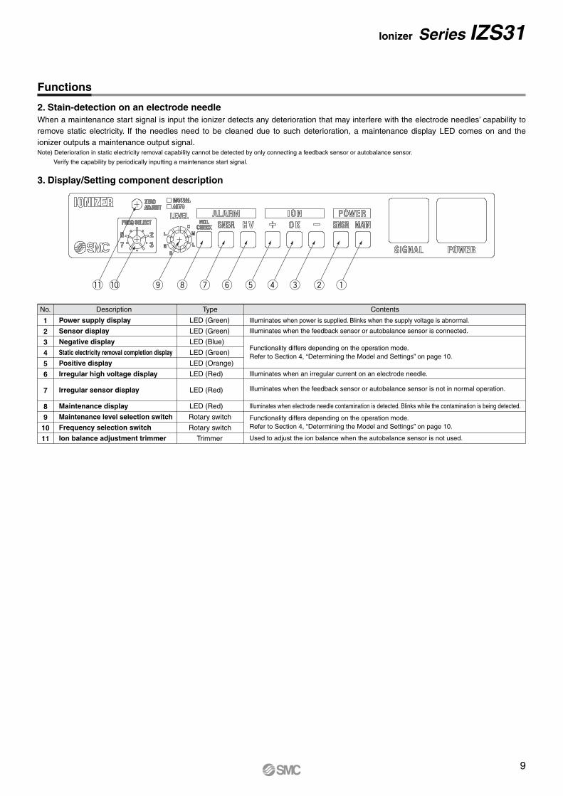
When a maintenance start signal is input the ionizer detects any deterioration that may interfere with the electrode needles’ capability to remove static electricity. If the needles need to be cleaned due to such deterioration, a maintenance display LED comes on and the ionizer outputs a maintenance output signal.Note) Deterioration in static electricity removal capability cannot be detected by only connecting a feedback sensor or autobalance sensor.
Verify the capability by periodically inputting a maintenance start signal.
2. Stain-detection on an electrode needle
3. Display/Setting component description
No. Description
Power supply display
Sensor display
Negative display
Static electricity removal completion display
Positive display
Irregular high voltage display
Irregular sensor display
Maintenance display
Maintenance level selection switch
Frequency selection switch
Ion balance adjustment trimmer
LED (Green)
LED (Green)
LED (Blue)
LED (Green)
LED (Orange)
LED (Red)
LED (Red)
LED (Red)
Illuminates when power is supplied. Blinks when the supply voltage is abnormal.
Illuminates when the feedback sensor or autobalance sensor is connected.
Illuminates when an irregular current on an electrode needle.
Illuminates when electrode needle contamination is detected. Blinks while the contamination is being detected.
Used to adjust the ion balance when the autobalance sensor is not used.
Functionality differs depending on the operation mode.Refer to Section 4, “Determining the Model and Settings” on page 10.
Type Contents
1
2
3
4
5
6
7
8
9
10
11
Illuminates when the feedback sensor or autobalance sensor is not in normal operation.
Functionality differs depending on the operation mode.Refer to Section 4, “Determining the Model and Settings” on page 10.
!1 !0 o i u y t r e w q
Ionizer Series IZS31
Rotary switch
Rotary switch
Trimmer
9
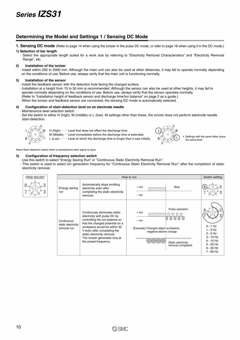
Determining the Model and Settings 1 / Sensing DC Mode
1. Sensing DC mode (Refer to page 14 when using the ionizer in the pulse DC mode, or refer to page 18 when using it in the DC mode.)
1) Selection of bar length· Select the appropriate length suited for a work size by referring to “Electricity Removal Characteristics” and “Electricity Removal
Range”, etc.
2) Installation of the ionizer· Install within 200 to 2000 mm. Although the main unit can also be used at other distances, it may fail to operate normally depending on the conditions of use. Before use, always verify that the main unit is functioning normally.
3) Installation of the sensor· Install the feedback sensor with the detection hole facing the charged surface.· Installation at a height from 10 to 50 mm is recommended. Although the sensor can also be used at other heights, it may fail to operate normally depending on the conditions of use. Before use, always verify that the sensor operates normally.(Refer to “Installation height of feedback sensor and discharge time/Ion balance” on page 2 as a guide.)
· When the ionizer and feedback sensor are connected, the sensing DC mode is automatically selected.
4) Configuration of stain-detection level on an electrode needle· Maintenance level selection switch· Set the switch to either H (high), M (middle) or L (low). At settings other than these, the ionizer does not perform electrode needle
stain-detection.
Note) Stain-detection starts when a maintenance start signal is input.
5) Configuration of frequency selection switch· Use this switch to select “Energy Saving Run” or “Continuous Static Electricity Removal Run”.· This switch is used to select ion generation frequency for “Continuous Static Electricity Removal Run,” after the completion of static
electricity removal.
+ ion Stop
– ion
+ ionPulse operation
Static electricityremoval completed
– ion
(Example) Charged object workpiece: negative electric charge
How to run Switch setting
0···1 Hz1···3 Hz2···5 Hz3···10 Hz4···15 Hz5···20 Hz6···30 Hz7···60 Hz
Automatically stops emitting electricity even after completing the static electricity removal.
Continously eliminates static electricity with pulse DC by controlling the ion balance so that the charged potential on a workpiece would be within 30 V even after completing the static electricity removal.The ionizer generates ions at the preset frequency.
H (High) Level that does not effect the discharge time.M (Middle) Level immediately before the discharge time is extended.L (Low) Level at which the discharge time is longer than it was initially.
∗ Settings with the same letter sharethe same level.
Energy savingrun
Continuousstatic electricityremoval run
Series IZS31
10

Determining the Model and Settings 1 / Sensing DC Mode
6) Wiring of power supply cable· Connect the dedicated power supply cable.
7) Air piping· For single-side piping, block the unused port with the M-5P plug supplied with the ionizer.
GND
Class-D ground
DC power supply
Blue
Brown
Connection with ionizer driving power supply
Wiring of input/output signal power suply cableSymbol Cable color
DC2 (+)
DC2 (–)
IN1
IN2
—
—
OUT1
OUT2
OUT3
Red
Black
Yellow green
Gray
White
Orange
Peach
Yellow
Purple
—
—
Power supply 24 VDC
Power supply GND
Electricity dischargestop signal
Maintenance start signal
—
—
Maintenance output signal
Irregular signal
—
—
Description Connection needs Contents
Symbol Cable color
DC1 (+)
DC1 (–)
OUT4
Brown
Blue
Green
Power supply 24 VDC
Power supply GND [FG]
Sensor monitor output
Ionizer driving power supply cable
Description Connection needs Contents
∗ DC1 (–) [Blue] is sure to ground it according to class-D. If the terminal is not grounded, the ionizer may malfunction.
: Minimum wiring requirement for ionizer operation: Wiring necessary to use various functions—: Wiring not required in the sensing DC mode. Exercise caution to ensure that this wire does not short-circuit to other wires.
Outputs the workpiece’s electrostatic potential as an analog signal (1 to 5 V).
Electricity removalcompletion signal
Input/output signal power supply cable
Signal to be input when determining the necessity of electrode needle maintenance
Signal to be output when the workpiece’s electrostatic potential is outside 30 V orwhen electrode needle contamination is being detected.
Signal to be output when electrode needle maintenance is necessary.
Outputs when signal is irregular high voltage, irregular sensor, irregular CPU (B type contact output)
Signal for enabling/disabling discharging(NPN specification) Discharging is enabled when connected to DC2 (–) [Black].(PNP specification) Discharging is enabled when connected to DC2 (+) [Red].
+24 VDC
11
Ionizer Series IZS31
Determining the Model and Settings 1 / Sensing DC Mode
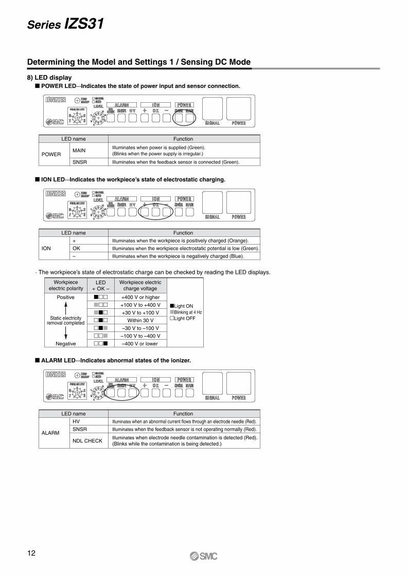
8) LED display POWER LED···Indicates the state of power input and sensor connection.
LED name
POWERMAIN
SNSR
Illuminates when power is supplied (Green).(Blinks when the power supply is irregular.)
Illuminates when the feedback sensor is connected (Green).
Function
ION LED···Indicates the workpiece’s state of electrostatic charging.
LED name
ION
+
OK
–
Illuminates when the workpiece is positively charged (Orange).
Illuminates when the workpiece electrostatic potential is low (Green).
Illuminates when the workpiece is negatively charged (Blue).
Function
· The workpiece’s state of electrostatic charge can be checked by reading the LED displays.
ALARM LED···Indicates abnormal states of the ionizer.
ALARM
HV
SNSR
NDL CHECK
Illuminates when an abnormal current flows through an electrode needle (Red).
Illuminates when the feedback sensor is not operating normally (Red).
Illuminates when electrode needle contamination is detected (Red). (Blinks while the contamination is being detected.)
Positive
Negative
Light ONBlinking at 4 HzLight OFF
LED name Function
Workpieceelectric polarity
Workpiece electriccharge voltage
LED+ OK –
+400 V or higher
+100 V to +400 V
+30 V to +100 V
Within 30 V
–30 V to –100 V
–100 V to –400 V
–400 V or lower
Static electricityremoval completed
Series IZS31
12

Determining the Model and Settings 1 / Sensing DC Mode
9) AlarmAlarm item Description Corrective actions
High voltage irregularityGives notification of the occurrence of an abnormal current, such as high-voltage leakage. The ionizer stops discharging, turns on the HV ALARM display, and outputs a fault signal.
Turn off the power, solve the problem, then turn the power on again. Alternatively, turn the discharge stop signal off, then on.
Turn off the power, solve the problem, then turn the power on again. Alternatively, turn the discharge stop signal off, then on.
Turn off the power, solve the problem, then turn the power on again. Alternatively, turn the discharge stop signal off, then on.
Sensor irregularityGives notification that the feedback sensor has become unable to operate normally. The ionizer turns on the SNSR ALARM display and outputs a fault signal.
CPU irregularityGives notification of the occurrence of a failure in the CPU due to noise, etc. All of the LED displays blink and a fault signal is output.
Electrode needlemaintenance
Gives notification that electrode needle maintenance is necessary. The NDL CHECK ALARM display comes on and a maintenance output signal is output.
Turn off the power, clean the electrode needles, and turn the power on again.
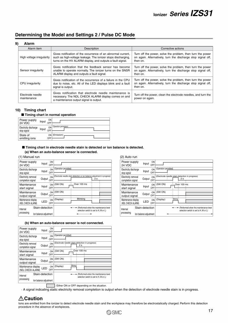
10) Timing chart Timing chart in normal operation
Timing chart in electrode needle stain is detected.
Electric charge of workpiece
Power supply 24 VDC
Sensor monitor output
Input
Input
Output
Output
LED
ON
OFF
30 V
0 V
ON (Operation permitted)
(Static electricityremoval in progress)
(Output)
(Display)
OFF
ON
OFF
ON
OFF
ON
OFFDisplay of electric charge(ION LED display)
Power supply 24 VDC Input
Input
Output
Input
Output
LED
ON
OFF
ON (Operation permitted)
(Static electricityremoval in progress) 2 s
(Electrode needle stain is being detected)
(SW ON)
(SW ON)
(Display)
OFF
ON
OFF
ON
OFF
ON
OFF
ON
OFFMaintenance display(NDL CHECK ALARM)
Blinking
Over 100 ms
: Either ON or OFF depending on the situation.
· A signal indicating static electricity removal completion is output when the detection of electrode needle stain is in progress.
Ions are emitted from the ionizer to detect electrode needle stain and the workpiece may therefore be electrostatically charged. Perform this detection procedure in the absence of workpieces.
Caution
Electricity dischargestop signal
Electricity removalcompletion signal
Electricity dischargestop signal
Electricity removalcompletion signal
Maintenance startsignal
Maintenance outputsignal
13
Ionizer Series IZS31

Determining the Model and Settings 2 / Pulse DC Mode
1) Selection of bar length· Determine the length suited for a work size, referring to the “Electricity Removal Characteristics” and “Electricity Removal Range”,
etc.2) Installation of the ionizer
· Install the ionizer within 50 to 2000 mm of the object requiring electricity removal. However, install the main unit at a distance from 100 to 2000 mm when using an autobalance sensor. Although the main unit can also be used at other distances, it may fail to operate normally depending on the conditions of use. Before use, always verify that the main unit is functioning normally.
3) Installation of the sensor· When adjusting the ion balance using a sensor, install an autobalance sensor.· Install the sensor immediately below the ionizer so that it is level with the workpiece. · When an autobalance sensor is connected, the balance adjustment trimmer settings are nullified.
4) Configuration of maintenance level selection switch· This switch is used to select “Manual Operation” or “Automatic Operation” when an autobalance sensor is connected to adjust the ion
balance.
When an autobalance sensor is not used.When an autobalance sensor is not used, set the switch to AUTO. Then, adjust the ion balance manually using the balance adjustment trimmer.
· Configuration of stain-detection level on an electrode needle.· Set the switch to either H (high), M (middle) or L (low). At settings other than these, the ionizer does not perform electrode needle
stain-detection
· Stain-detection starts when a maintenance start signal is input.· When the switch is set to H, M or L, the ionizer performs electrode needle stain-detection and then adjusts the ion balance.
AUTO MANUAL
Details of operation Switch setting
Manualoperation
Automaticoperation
MANUAL
AUTO
When a maintenance start signal is input or the ionizer is turned on, the ionizer detects electrode needle contamination according to ion balance adjustment and detection level settings.An ion balance adjustment value for each ion generation frequency is retained. When the ion generation frequency is changed, adjust the ion balance.After adjustment, the autobalance sensor may be removed as ion balance adjustment will not be performed again until a maintenance start signal is input.
The ionizer continuously adjusts the ion balance. When the autobalance sensor is removed, adjust the ion balance manually using the balance adjustment trimmer.
∗ Set the switch according to the stain-detection level.
Ion balance adjustment trimmer
H (High) Level not influential to the discharge timeM (Middle) Level immediately before the discharge time elongates.L (Low) Level at which the discharge time is longer than it initially was.
Series IZS31
2. Pulse DC mode
14

Determining the Model and Settings 2 / Pulse DC Mode
6) Wiring of power supply cable · Connect the dedicated power supply cable.
Connection with ionizer driving power supply Symbol Cable color
—
Ionizer driving power supply cable
—
Description Connection needs Contents
5) Frequency selection switch setting· Selects ion generation frequency
Ion generation frequency Switch setting
1 Hz
3 Hz
5 Hz
10 Hz
15 Hz
20 Hz
30 Hz
60 Hz
0
1
2
3
4
5
6
7
DC1 (+)
DC1 (–)
OUT4
Power supply 24 VDC
Power supply GND [FG]
Sensor monitor output
Brown
Blue
Green
∗ DC1 (–) [Blue] is sure to groung it according to class-D. If the terminal is not grounded, the ionizer may malfunction. GND
Wiring of input/output signal power suply cable
Class-D ground
DC power supply
Blue
Brown
Symbol Cable color
DC2 (+)
DC2 (–)
IN1
IN2
—
—
OUT1
OUT2
OUT3
Red
Black
Yellow green
Gray
White
Orange
Pink
Yellow
Purple
—
—
Power supply 24 VDC
Power supply GND
Electricity dischargestop signal
Maintenance start signal
—
—
Maintenance output signal
Irregular signal
—
—
Description Connection needs Contents
: Minimum wiring requirement for ionizer operation: Wiring necessary to use various functions—: Wiring not required in the sensing DC mode. Exercise caution to ensure that this wire does not short-circuit to other wires.
7) Air piping· For single-side piping, block the unused port with the M-5P plug supplied with the ionizer.
Electricity removalcompletion signal
Input/output signal power supply cable
Signal to be input when determining the necessity of electrode needle maintenance
Signal to be output when the workpiece’s electrostatic potential is outside 30 V orwhen electrode needle contamination is being detected.
Signal to be output when electrode needle maintenance is necessary.
Outputs when signal is irregular high voltage, irregular sensor, irregular CPU (B type contact output)
Signal for enabling/disabling discharging(NPN specification) Discharging is enabled when connected to DC2 (–) [Black].(PNP specification) Discharging is enabled when connected to DC2 (+) [Red].
+24 VDC
15
Ionizer Series IZS31

Determining the Model and Settings 2 / Pulse DC Mode
ION LED···Indicates the polarity of ions being emitted and the ion balance.
LED name
ION
+
OK
–
Illuminates that positive ions are being emitted from the ionizer (Orange).
[With autobalance sensor] Indicates the state of ion balancing (Green). [Without autobalance sensor] Remains turned off.
Illuminates that negative ions are being emitted from the ionizer (Blue).
Function
· The state of ion balancing can be checked by reading the LED display.
LED name
ALARM
HV
SNSR
NDL CHECK
Function
Light ON (or Blinking)
Light OFF
Under 30 V
Over 30 V
Ion balance OK LED
∗ The OK LED display blinks when the ion balance is approaching the limits of the adjustable range, signaling that the time for electrode needle maintenance is near.
8) LED display POWER LED···Indicates the state of power input and sensor connection.
LED name
POWERMAIN
SNSR
Illuminates when power is supplied (Green).(Blinks when the power supply is irregular.)
Illuminates when the feedback sensor is connected (Green).
Function
ALARM LED···Indicates abnormal states of the ionizer.
Illuminates when an abnormal current flows through an electrode needle (Red).
Illuminates when the autobalance sensor is not operating normally (Red).
Illuminates when electrode needle stain is detected (Red). (Blinks when the stain is being detected.)
Series IZS31
16
Determining the Model and Settings 2 / Pulse DC Mode
Input
Input
ONOFF
(Emission)
ONOFF
ONOFF
Timing chart in electrode needle stain is detected or ion balance is detected. (a) When an auto-balance sensor is connected.
(1) Manual run
Input
Input
Output
Input
Output
LED
Input
Input
Output
Input
Output
LED
ONOFF
(Electrode needle stain-detection or ion balance adjustment in progress)2 s
Over 100 ms
(Performed when the maintenance levelselection switch is set to H, M or L)
ONOFF
ONOFF
ONOFF
ONOFF
ONOFF
(b) When an auto-balance sensor is not connected.
(2) Auto run
Internalprocessing
Stain-detection
Ion balance adjustment
ONOFF
2 s
Blinking
(Performed when the maintenance levelselection switch is set to H, M or L)
ONOFF
ONOFF
ONOFF
ONOFF
ONOFF
(Electrode needle stain-detection in progress)
Over 100 ms
ONOFF
2 s
ONOFF
ONOFF
ONOFF
ONOFF
ONOFF
(Electrode needle stain-detection in progress)
Over 100 ms
High voltage irregularity
Sensor irregularity
CPU irregularity
Electrode needlemaintenance
(Operation permission)Electricity dischargestop signal
State ofemitting ions
Power supply24 VDC
(Operation permitted)
(Operation permitted)
(SW ON)
(SW ON)
(Display)
(Operation permitted)
(SW ON)
(SW ON)
(Display)
(SW ON)
(SW ON)
(Display)
Blinking
Blinking
Maintenance display(NDL CHECK ALARM)
Electricity dischargestop signalElectricity removalcompletion signal
Power supply24 VDC
Maintenancestart signal
Input
Input
Output
Input
Output
LED
Maintenanceoutput signalMaintenance display(NDL CHECK ALARM)
Electricity dischargestop signalElectricity removalcompletion signal
Power supply24 VDC
Maintenancestart signal
Maintenanceoutput signalMaintenance display(NDL CHECK ALARM)
Electricity dischargestop signalElectricity removalcompletion signal
Power supply24 VDC
Maintenancestart signal
9) AlarmAlarm item Description Corrective actions
10) Timing chart Timing chart in normal operation
Internalprocessing
Stain-detection
Ion balance adjustment
(Performed when the maintenance levelselection switch is set to H, M or L)Internal
processing
Stain-detection
Ion balance adjustment
: Either ON or OFF depending on the situation.
· A signal indicating static electricity removal completion is output when the detection of electrode needle stain is in progress.
Ions are emitted from the ionizer to detect electrode needle stain and the workpiece may therefore be electrostatically charged. Perform this detection procedure in the absence of workpieces.
Caution
Maintenance output signal
17
Ionizer Series IZS31
Gives notification of the occurrence of an abnormal current, such as high-voltage leakage. The ionizer stops discharging, turns on the HV ALARM display, and outputs a fault signal.
Turn off the power, solve the problem, then turn the power on again. Alternatively, turn the discharge stop signal off, then on.
Turn off the power, solve the problem, then turn the power on again. Alternatively, turn the discharge stop signal off, then on.
Turn off the power, solve the problem, then turn the power on again. Alternatively, turn the discharge stop signal off, then on.
Gives notification that the feedback sensor has become unable to operate normally. The ionizer turns on the SNSR ALARM display and outputs a fault signal.
Gives notification of the occurrence of a failure in the CPU due to noise, etc. All of the LED displays blink and a fault signal is output.
Gives notification that electrode needle maintenance is necessary. The NDL CHECK ALARM display comes on and a maintenance output signal is output.
Turn off the power, clean the electrode needles, and turn the power on again.
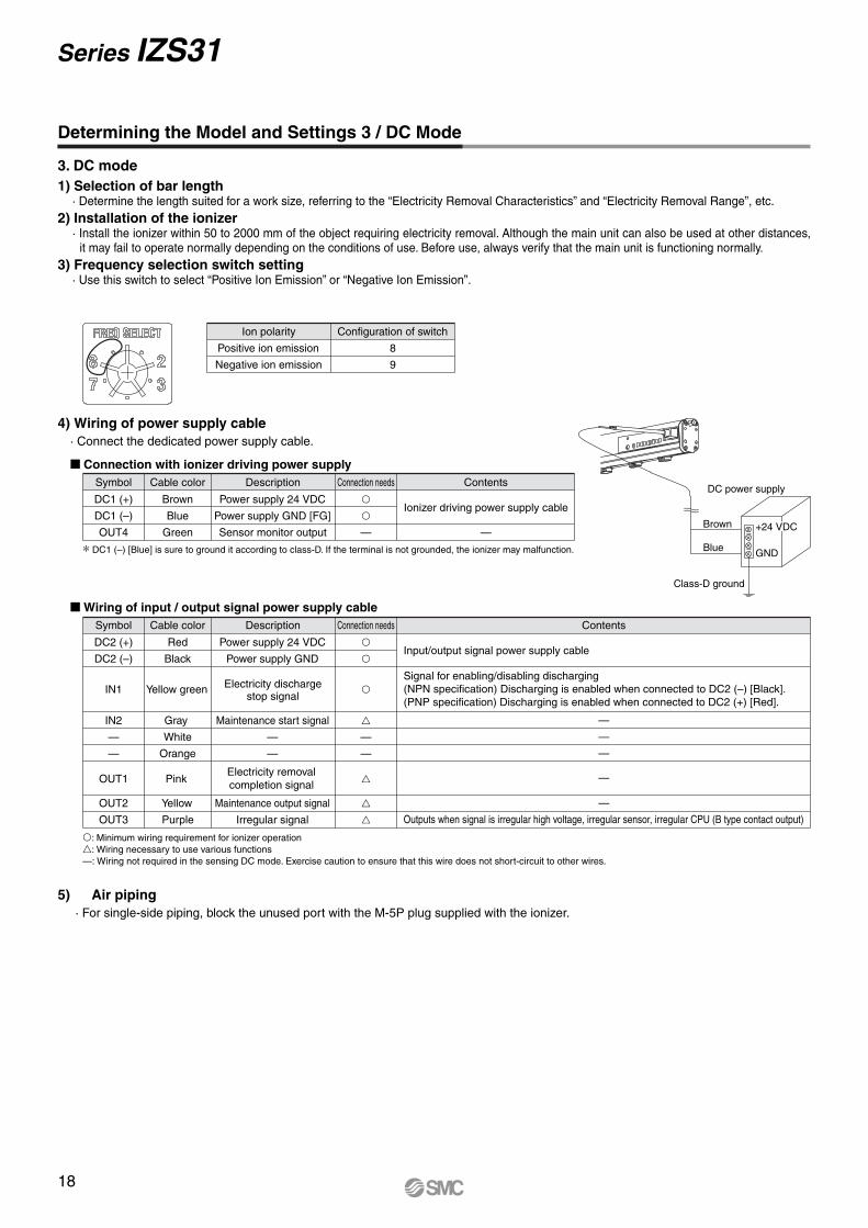
Determining the Model and Settings 3 / DC Mode
Ion polarity Configuration of switch
Positive ion emission
Negative ion emission
8
9
1) Selection of bar length· Determine the length suited for a work size, referring to the “Electricity Removal Characteristics” and “Electricity Removal Range”, etc.
2) Installation of the ionizer· Install the ionizer within 50 to 2000 mm of the object requiring electricity removal. Although the main unit can also be used at other distances,
it may fail to operate normally depending on the conditions of use. Before use, always verify that the main unit is functioning normally.3) Frequency selection switch setting
· Use this switch to select “Positive Ion Emission” or “Negative Ion Emission”.
3. DC mode
4) Wiring of power supply cable · Connect the dedicated power supply cable.
Connection with ionizer driving power supplySymbol Cable color
—
Ionizer driving power supply cable
—
Description Connection needs Contents
DC1 (+)
DC1 (–)
OUT4
Power supply 24 VDC
Power supply GND [FG]
Sensor monitor output
Brown
Blue
Green
∗ DC1 (–) [Blue] is sure to ground it according to class-D. If the terminal is not grounded, the ionizer may malfunction. GND
Class-D ground
DC power supply
Blue
Brown
Wiring of input / output signal power supply cableSymbol Cable color
DC2 (+)
DC2 (–)
IN1
IN2
—
—
OUT1
OUT2
OUT3
Red
Black
Yellow green
Gray
White
Orange
Pink
Yellow
Purple
—
—
Power supply 24 VDC
Power supply GND
: Minimum wiring requirement for ionizer operation: Wiring necessary to use various functions—: Wiring not required in the sensing DC mode. Exercise caution to ensure that this wire does not short-circuit to other wires.
5) Air piping· For single-side piping, block the unused port with the M-5P plug supplied with the ionizer.
Electricity dischargestop signal
Maintenance start signal
—
—
Maintenance output signal
Irregular signal
—
—
—
—
—
Description Connection needs Contents
Input/output signal power supply cable
Outputs when signal is irregular high voltage, irregular sensor, irregular CPU (B type contact output)
Signal for enabling/disabling discharging(NPN specification) Discharging is enabled when connected to DC2 (–) [Black].(PNP specification) Discharging is enabled when connected to DC2 (+) [Red].
Electricity removalcompletion signal
Series IZS31
18
+24 VDC
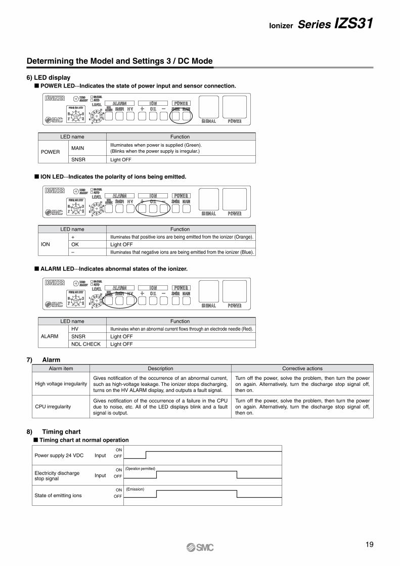
Determining the Model and Settings 3 / DC Mode
LED name
ION
+
OK
–
Illuminates that positive ions are being emitted from the ionizer (Orange).
Light OFF
Illuminates that negative ions are being emitted from the ionizer (Blue).
Function
LED name
ALARM
HV
SNSR
NDL CHECK
Illuminates when an abnormal current flows through an electrode needle (Red).
Light OFF
Light OFF
Function
7) Alarm
High voltage irregularity
CPU irregularity
8) Timing chart Timing chart at normal operation
Power supply 24 VDC
State of emitting ions
Input
Input
ON
OFF
ON
OFF
ON
OFF
LED name
POWERMAIN
SNSR Light OFF
Function
(Emission)
(Operation permitted)Electricity dischargestop signal
6) LED display POWER LED···Indicates the state of power input and sensor connection.
ION LED···Indicates the polarity of ions being emitted.
Illuminates when power is supplied (Green).(Blinks when the power supply is irregular.)
ALARM LED···Indicates abnormal states of the ionizer.
Alarm item Description Corrective actions
Gives notification of the occurrence of an abnormal current, such as high-voltage leakage. The ionizer stops discharging, turns on the HV ALARM display, and outputs a fault signal.
Turn off the power, solve the problem, then turn the power on again. Alternatively, turn the discharge stop signal off, then on.
Turn off the power, solve the problem, then turn the power on again. Alternatively, turn the discharge stop signal off, then on.
Gives notification of the occurrence of a failure in the CPU due to noise, etc. All of the LED displays blink and a fault signal is output.
19
Ionizer Series IZS31

Inte
rnal
circ
uit
Input/Output signal circuit
INPUT
INPUT
OUTPUT
OUTPUT
PLC
Ionizer
FG
+24 V
+24 V
+24 V
+24 V
Analog input
Over 10kΩ
Load
PNP specification NPN specification
Note) The sensor monitor output (OUT4: Green) is not isolated from the ionizer’s internal circuit and is therefore wired to the FG terminal.
Isolation circuit(Photo coupler)
Isolation circuit(Photo coupler)
Isolation circuit(Photo coupler)
Isolation circuit(Photo coupler)
Isolation circuit(Photo coupler)
Isolation circuit(Photo coupler)
Isolation circuit(Photo coupler)
Isolation circuit(Photo coupler)
Isolation circuit(Photo coupler)
Isolation circuit(Photo coupler)
or
or
Inte
rnal
circ
uit
Input/Output signal circuit
INPUT
INPUTOUTPUT
OUTPUT
PLC
Brown: DC1 (+)Blue: DC1 (–)
Red: DC2 (+)Black: DC2 (–)
Yellow green: IN1
Gray: IN2
Pink: OUT1
Yellow: OUT2
Purple: OUT3
Green: OUT4
Brown: DC1 (+)Blue: DC1 (–)
Red: DC2 (+)Black: DC2 (–)
Yellow green: IN1
Gray: IN2
Pink: OUT1
Yellow: OUT2
Purple: OUT3
Green: OUT4
Ionizer
FG
+24 V
Analog input
Over 10kΩ
Load
or
or
+24 V
+24 V
Connection Circuit of Power Cable
Series IZS31
+: Ionizer driving power supply
GND: 24 VDC 10%
+: Input/Output signal power supply
GND: 24 VDC 10%
+: Ionizer driving power supply
GND: 24 VDC 10%
+: Input/Output signal power supply
GND: 24 VDC 10%
20

Hexagon sockethead cap screwM4 x 6(Accessory)
4015 23
14 3
5.4
1839
24
Angle adjustable
31
22 4.5
2-5.
4
20
(33)
(31)
2
32
Ionizer full length (L)
100
27
100
27
2
IZS31--
Ionizer full length (L)
IZS31--M5 screw for mounting
Angle adjustable(90)
6.5
33
22
When mountedoutside in
10
4 x M4 x 0.7 depth 5(For mounting, opposite side: Same)
Electrode cartridgeMaintenance level selection switch
14 14
16 36 2030
19 14
L
KJH04-M5-X34
17
52
1620 58
Frequency selection switch
Ion balance adjustment trimmer
2580 x (n-1) 70
Dimensions
Ionizer / IZS31--
End bracket / IZS31-BE
Center bracket / IZS31-BM
IZS31-300IZS31-380IZS31-620IZS31-780IZS31-1100IZS31-1260IZS31-1500IZS31-1900IZS31-2300
n (No. of electrode cartridges), L Dimension
L (mm)300380620780
11001260150019002300
nPart no.3479
1315182328
Center bracketNone
With 1 pc.With 2 pcs.
Bar length (mm)300, 380, 620, 7801100, 1260, 1500
1900, 2300
Note) Number of center brackets included in a model with brackets (Refer to “How to Order” on page 4).
FittingM-5P-X112
KJH04-M5-X34 Note)
Bar length (mm)300, 380, 620, 7801100, 1260, 1500
1900, 2300
21
Note) Plug (M-5P-X112) is shipped together.
Ionizer Series IZS31

(6.2
)
L
3
60
7
(Red)
12
1
SM
C
8.8
8.8
11
61
50.5
13
0.5
3500
ø4.
8
1500
ø4.
8
ø10
.2
16.6
ø10
.2 815
2 x R3.3
0.5
13
ø10
.2
6.5 7.8
7.7 60
14
69
78
23
7
913
58
87.5
25
10
1
6
Amplifier partHead part 2 x ø3.4 2 x ø3.4
Detection part
12
5
71
14.5
95
98
ø6.
6
0.2
0.2
20
8.8
3500
ø4.
8
1500
ø4.
8
ø10
.2
815
13
ø10
.2
7.8
7.7 60
14
69
78
23
2 x ø3.4
1
6
Amplifier partHead part 2 x ø3.4
Detection part
Feedback sensor / IZS31-DF
Autobalance sensor / IZS31-DG
Power supply cable / IZS31-CP
Model3000
10000
L (mm)IZS31-CPIZS31-CPZ
22
Dimensions
Series IZS31
2 x ø6.6 deep counterbored hole, 5.7 deep(height of screw seating surface: 8.8)
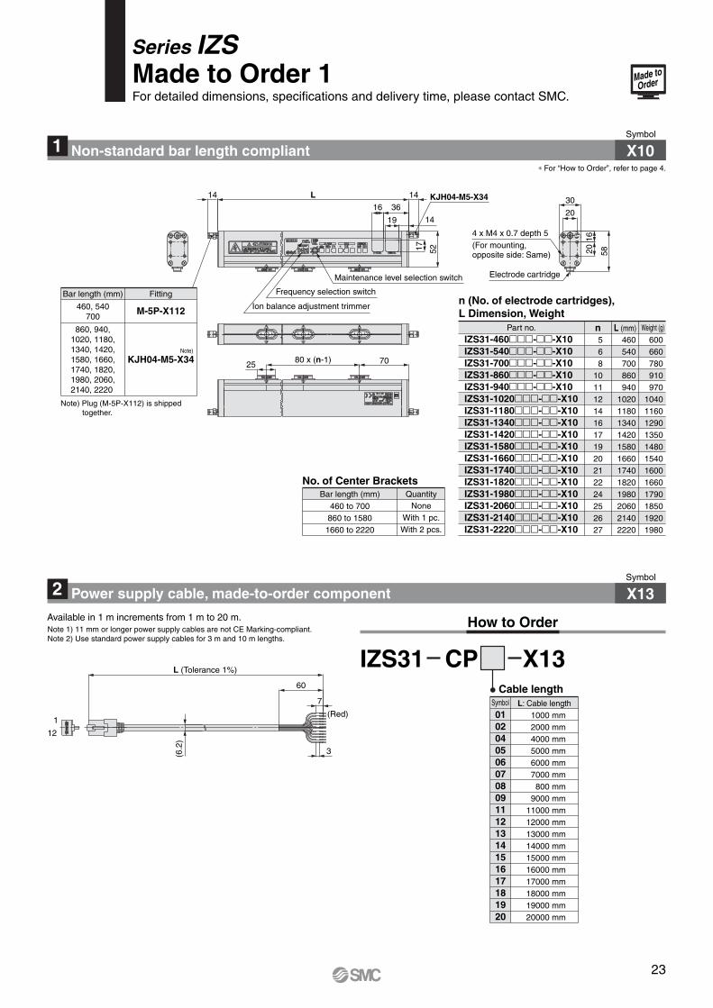
1 Non-standard bar length compliant X10Symbol
∗ For “How to Order”, refer to page 4.
2 Power supply cable, made-to-order component Symbol
X13
Cable length
How to Order
IZS31 CP X13
Available in 1 m increments from 1 m to 20 m.
1000 mm2000 mm4000 mm5000 mm6000 mm7000 mm800 mm
9000 mm11000 mm12000 mm13000 mm14000 mm15000 mm16000 mm17000 mm18000 mm19000 mm20000 mm
010204050607080911121314151617181920
L: Cable lengthSymbol
(6.2
)
L (Tolerance 1%)
3
60
7
(Red)
12
1
No. of Center BracketsQuantity
NoneWith 1 pc.With 2 pcs.
Bar length (mm)460 to 700
860 to 15801660 to 2220
n (No. of electrode cartridges), L Dimension, Weight
Part no. n L (mm)IZS31-460--X10IZS31-540--X10IZS31-700--X10IZS31-860--X10IZS31-940--X10IZS31-1020--X10IZS31-1180--X10IZS31-1340--X10IZS31-1420--X10IZS31-1580--X10IZS31-1660--X10IZS31-1740--X10IZS31-1820--X10IZS31-1980--X10IZS31-2060--X10IZS31-2140--X10IZS31-2220--X10
568
1011121416171920212224252627
460540700860940
102011801340142015801660174018201980206021402220
Weight (g)
600660780910970
104011601290135014801540160016601790185019201980
Fitting
M-5P-X112
KJH04-M5-X34
Bar length (mm)
460, 540700
860, 940,1020, 1180,1340, 1420,1580, 1660,1740, 1820,1980, 2060,2140, 2220
Electrode cartridgeMaintenance level selection switch
14 14
16 3620
30
19 14
L KJH04-M5-X34
17 52
1620 58
Frequency selection switch
Ion balance adjustment trimmer
2580 x (n-1) 70
Note)
Note) Plug (M-5P-X112) is shipped together.
4 x M4 x 0.7 depth 5(For mounting, opposite side: Same)
Series IZSMade to Order 1For detailed dimensions, specifications and delivery time, please contact SMC.
23
Made toOrder
Note 1) 11 mm or longer power supply cables are not CE Marking-compliant.Note 2) Use standard power supply cables for 3 m and 10 m lengths.

3 Model with 40 mm-pitch electrode cartridgesSymbol
X15Install the electrode cartridges at a 40 mm-pitch.(Standard pitch: 80 mm).
Note) The maximum bar length is 1260 mm. The air purge nozzles are arranged at an 80 mm-pitch.
n (No. of electrode cartridges), L Dimension, Weight
nIZS31-300--X15IZS31-380--X15IZS31-620--X15IZS31-780--X15IZS31-1100--X15IZS31-1260--X15
57
13172529
300380620780
11001260
480540740880
11401270
4 x M4 x 0.7 depth 5(For mounting, opposite side: Same)
Note) Plug (M-5P-X112) is shipped together.
Part no. L (mm) Weight (g)
Maintenance level selection switch
Air purge port: 80 mm between ports
KJH04-M5-X34
7025
52
1419
16 36
17
14
30
5820
L
40 x (n-1)
20
16
14
Frequency selection switch
Ion balance adjustment trimmerFitting
M-5P-X112
KJH04-M5-X34
Bar length (mm)300, 380,620, 780
1100, 1260
Electrode cartridge
Note)
24
Series IZSMade to Order 2For detailed dimensions, specifications and delivery time, please contact SMC.
Made toOrder


![M˚˛˝˙ˆ˙ˆˇ ˛ ˆ GS 1400 - : Home€¦ · C-Axis RPM max. min-1 100 1) 450 [560] 2) Table Load max. kg 3000 Rotary-Table C axis 1) 2) Clamping surface mm 780 x 780 mm with](https://img.dokumen.tips/doc/110x75/613051441ecc5158694404e1/m-gs-1400-home-c-axis-rpm-max-min-1-100-1-450-560.jpg)