Embed Size (px)
Citation preview
Friction 9(2): 288–300 (2021) ISSN 2223-7690 https://doi.org/10.1007/s40544-019-0337-8 CN 10-1237/TH
RESEARCH ARTICLE
Investigation on the wear of spur gears generated by modified cutter
Fangyan ZHENG1,3,*, Jun ZHANG2, Ligang YAO2, Rulong TAN3 1 School of Automotive Engineering, Wuhan University of Technology, Wuhan 430070, China 2 School of Mechanical Engineering and Automation, Fuzhou University, Fuzhou 350116, China 3 School of Mechanical Engineering, Chongqing University of Technology, Chongqing 400000, China
Received: 01 April 2018 / Revised: 19 February 2019 / Accepted: 21 October 2019
© The author(s) 2019.
Abstract: Tooth surface wear damage is one of the main causes of gearing system failure. Excessive wear leads
to tooth profile loss and an increase in transmission errors, as the worn gear surfaces are no longer conjugate.
Thus, the enhancement of gear durability against wear is important for gear application. Recent works show
that cutter modification can aid in reducing the tool wear in gear processing, while the wear performance of the
gears produced by modified cutters is still unknown. Therefore, this study focuses on the wear performance
of the gear generated by modified cutter. Numerical results show that the wear resistance can be enhanced
through proper cutter modification.
Keywords: gear wear; cutter modification; gear modification
1 Introduction
Spur gears, which are the key components in many
mechanical systems [1–3], are widely used in modern
industries, such as aerospace, marine, agriculture,
and construction [4–6]. As advanced driving systems
enable high speed, wear damages have become the
main cause of failure of gear components [7–10].
Thus, gear wear has been actively researched in
recent times, and some of these studies are focused
on wear mechanism and wear calculation methods.
For mild surface wear, Archard’s wear model [11]
is widely used, although it is rather imperfect. As
gear wear is usually regarded as a special case of
surface wear, research on gear wear can be dated
back to the doctoral thesis of Andersson [12]. Wu and
Chen [13] then proposed a simple wear calculation
method for spur gear and revealed that the worst wear
occurred at the beginning of the gear mesh (tooth
tips of the driven gear). Flodin and Andersson then
published a series of works on spur and helix gear
wear prediction [14, 15], in which a modified Archard’s
wear model was established, a “single point observation
principle” was used, and the tooth stiffness was con-
sidered through an empirical model developed by
Simon [16]. Brauer and Andersson [17] investigated
the wear in spur gears caused by interference using a
mixed finite element and analytical approach. They
validated that the interference was caused by deviation
from the ideal gear geometry and unfavorable defor-
mation during operation; Bajpai et al. [18] proposed
a wear prediction methodology for spur and helical
gears using a finite element-based gear contact
mechanics model in conjunction with Archard’s wear
formulation to predict the wear of contacting tooth
surfaces. They also investigated the influence of tooth
profile deviation through intentional tooth profile
modification [19]; Tunalioğlu and Tuç [20] researched
the wear in internal gears with the combination of
theoretical calculation and experiment. They designed
and manufactured a fatigue and wear test equipment
that was similar to Forschungsstelle für Zahnrader
* Corresponding author: Fangyan ZHENG, E-mail: [email protected]
Friction 9(2): 288–300 (2021) 289
∣www.Springer.com/journal/40544 | Friction
http://friction.tsinghuajournals.com
Nomenclature
( , )pf
l u r Cutter tooth modification function Tooth profile modification magnitude
0 Tooth profile modification range
c( , )r u r Tooth surface of the cutter with parabolic
modification
( , )u rc
n Tooth normals of the cutter with parabolic
modification
rs Translation distance of the rack in gear
generating
g Rotating angle of gear in gear generating
gr Pitch radius of the gear
g( , , )u r
gr Envelope surface of the rack
g Velocity of generated gear
cv Velocity of rack
g( , , )u r
cgv Relative velocity between the rack and
the gear
g( , , )u r
0cn Tooth normals of the rack in the ground
coordinate system ( , )u r
Gr Tooth surface of the modified spur gear
( , )u rG
n Tooth normals of the modified spur gear
i Rotating angle of drive gear in tooth
contact analysis (TCA)
o Rotating angle of driven gear in TCA
IOE Center distance of the gear pair
( , )u rGi
r Tooth surface of drive gear in TCA
( , )u rGo
r Tooth surface of driven gear in TCA
( , , )I
u r Fi
r Tooth surface of drive gear in ground
coordinate system in TCA
( , , )o
u r Fo
r Tooth surface of driven gear in ground
coordinate system in TCA
( , , )i i Iu rFin Tooth normals of drive gear in ground
coordinate system in TCA
( , , )o o ou rFon Tooth normals of driven gear in ground
coordinate system in TCA
( , , )i i I
u r i
v Velocity of contact points in drive gear
in TCA
( , , )o o o
u r o
v Velocity of contact points in driven gear
in TCA ( , , , , , )
i i o o I ou r u r
iov Relative velocity of the contact
points in TCA
iK Curvature of drive gear
oK Curvature of driven gear
ioK Relative curvature between the drive
and driven gears
cjn Number of instant contact points
oΤ Total torque applied to driven gear
jr Position vector in each contact point
jF Normal contact force in each contact point
jC Comprehensive stiffness matrix in contact
j Total deformation of the gear teeth
jn Unit normal vector of the contact point
HP Maximum pressure in each contact point
b Contact width l Tooth width
ja Semi-Hertzian contact width
i Poisson’s ratio for drive gear
o Poisson’s ratio for driven gear
h wear depth
wK Wear coefficient
is Slider distance in each micro segment
und Getreibbau [21] closed circuit power circulation
system in working principle. Masjedi and Khonsari
[22] developed a procedure to predict film thickness,
traction coefficient, and wear rate with provision
for the interactions between the surface asperities of
the teeth of gear. Additionally, Henneberg et al. [23]
proposed a quasi-stationary approach to achieve
particle concentration and distribution in gear oil for
performing the wear estimation.
Some other works have focused on enhancing the
wear resistance to render the gear system more durable:
Mao [24] adopted the micro-geometry modification
method to investigate gear fatigue wear reduction and
proposed an optimized micro-geometry gear tooth
through advanced non-linear finite element analysis.
İmrek and Düzcükoğlu [25] focused on the relationship
between wear and tooth width modification in
spur gears. They indicated that the wear depth of the
modified gear along the meshing area was almost
uniform and better than that of the unmodified gear;
Karpat and Ekwaro-Osire [26] studied the influence of
tip relief modification on spur gears with asymmetric
teeth to reveal that an excessive increase in tip relief
modification should be avoided, and the level of
290 Friction 9(2): 288–300 (2021)
| https://mc03.manuscriptcentral.com/friction
excessive increase was based on tip relief configuration;
PrabhuSekar and Sathishkumar [27, 28] proposed a
method for enhancing the wear resistance of normal
contact ratio spur gear pairs through non-standard
gears. They showed that the use of non-standard pinion
and gear of unequal tooth thickness could aid in
reducing the wear damage. Zhou et al. [29] investigated
the normal and tangential oil film stiffness of modified
spur gears with non-Newtonian elastohydrodynamic
lubrication. They revealed that the modification was
valid for inhibiting the jump of oil film stiffness and
improving the gear wear resistance. These studies
together established that reasonable flank modification
could aid in enhancing the gear wear resistance.
However, on one hand, as these works are conducted
based on an assumed gear tooth modified geometry,
realizing their proposed methods in practice is difficult
(gear modification is generally obtained by cutter
modification) [30–32]. On the other hand, as the
modified gears are not conjugate, transmission errors
and change of dynamic performance may occur [33].
Some studies focused on the tool wear that happens
during the cutting process. Bouzakis et al. [34, 35]
established a sophisticated numerical model to predict
tool wear in gear hobbing cutting process and revealed
that coated hob teeth performed better than the
uncoated ones, and tooth profile geometry influenced
tool wear. Claudin and Rech [36] developed a new
rapid characterization method to enhance the wear
resistance of hob in gear manufacturing and established
that cutter edge geometry also influenced tool wear;
Karpuschewski et al. [37] investigated the geometrical
influence of tool profile on wear behavior in gear
hobbing. This study suggested that 30% of the total
piece cost for the hobbing process can be reduced
with the application of optimized tool profiles and
corresponding cutting parameters. These studies
established that tool profile modification could aid in
enhancing the wear resistance of the tool in the cutting
process. However, the wear performance of the gear
cut by modified cutter remained unknown.
Based on all the works discussed so far, this study
aims to investigate the wear performance of spur
gears with tooth profiles generated by modified
hobbing cutters. Firstly, the tooth geometry of spur
gears generated by modified cutters is obtained,
including the tooth modification of basic rack generator
and tooth surface of the modified gear. Then the tooth
wear calculation is discussed in detail, including the
tooth contact analysis, contact force calculation, and
wear depth calculation. Finally, the wear performance
under different cutter modifications is discussed by
considering the planet gear and sun gear of an
epicyclical transmission used in the wheel hub of an
electric automobile as an example, establishing that
wear resistance can be enhanced with appropriate
cutter modification.
2 Tooth geometry of spur gears with cutter
modification
Face-hobbing cutter is widely used in the manufacture
of external spur gears [38]. As the basic geometry of
the cutter includes a rack, the cutting process can be
regarded as the meshing of a gear and a rack [39].
The modified gear tooth geometry should thus be
deduced based on the modified cutter and the kinematic
relations generated.
2.1 Tooth modification for the rack generator
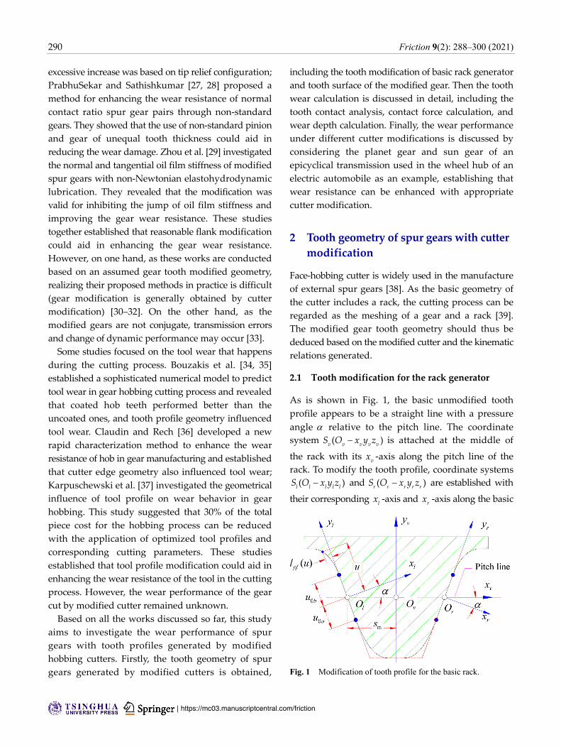
As is shown in Fig. 1, the basic unmodified tooth
profile appears to be a straight line with a pressure
angle relative to the pitch line. The coordinate
system ( )v v v v v
S O x y z is attached at the middle of
the rack with its v
x -axis along the pitch line of the
rack. To modify the tooth profile, coordinate systems
( )l l l l l
S O x y z and ( )r r r r r
S O x y z are established with
their corresponding l
x -axis and r
x -axis along the basic
Fig. 1 Modification of tooth profile for the basic rack.
Friction 9(2): 288–300 (2021) 291
∣www.Springer.com/journal/40544 | Friction
http://friction.tsinghuajournals.com
unmodified tooth profile. In coordinate systems l
S
and r
S , the tooth profile is defined by parameter u .
Two parameters 0a
u and 0b
u are used to define the
starting and ending points of modification, and function
( )pf
l u is used to present the offset of the modification.
In this study, drawn from the research in Ref. [40], a
parabolic function is used to modify the tooth profile,
which can be defined in coordinate systems l
S and
rS as follows:
2
0 0
0 0
2
0 0
( ) ,
( , ) 0,
( ) ,
pf
u u u u
l u r u u u
u u u u
(1)
where 0 0
( ) / cos( )f
u h r , is used to define the
tooth profile modification magnitude, and 0 is used
to define the tooth profile modification range.
The origins of coordinate systems l
S and r
S ,
respectively l
O and r
O , are the intersection points
of the pitch line and unmodified tooth profile. Their
distance from v
O denotes the tooth thickness modifi-
cation of the gear m
s .
Thus, the tooth surface of the cutter with parabolic
modification can be obtained as follows:
T
, ( ) 0, 1( ) pfl ur uuc vl rMr (2)
where
mcos( ) sin( ) 0 ( )
sin( ) cos( ) 0 0
0 0 0 0
0 0 0 1
s r
,
vl r
M .
Besides, the normals of the cutter are defined as
follows:
d ( , ) d ( , )( , )
d d
u r u ru r
u r c c
c
r rn (3)
2.1 Tooth surface of the modified gear
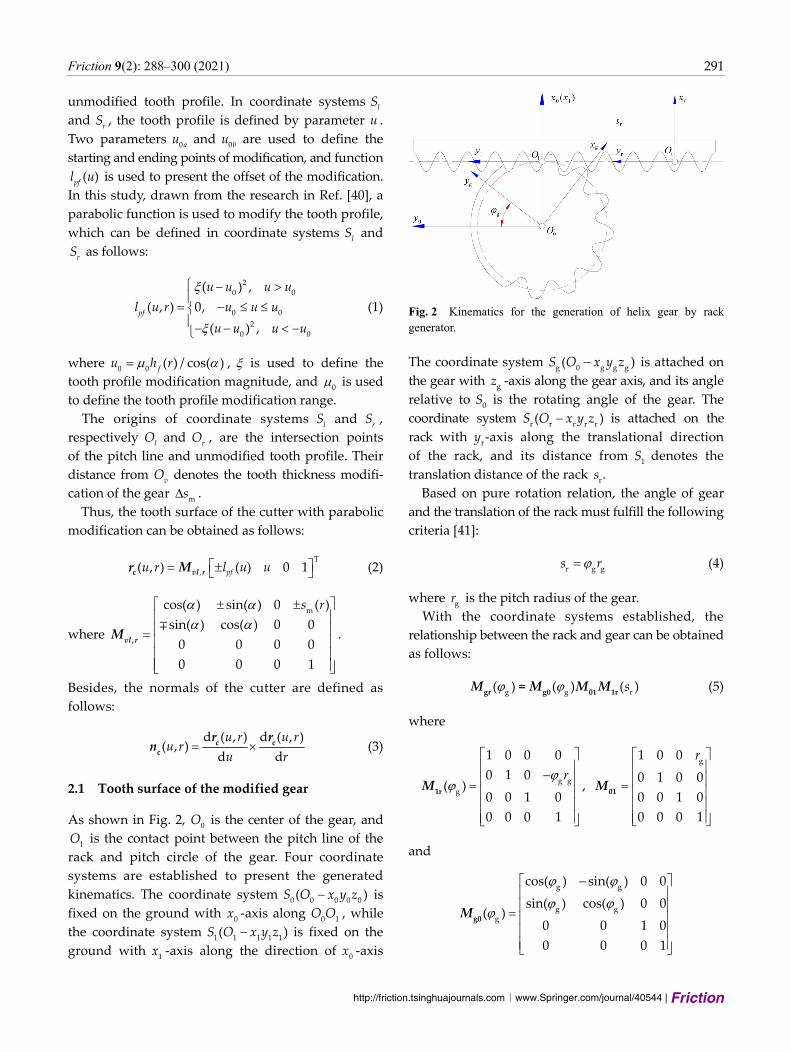
As shown in Fig. 2, 0
O is the center of the gear, and
1O is the contact point between the pitch line of the
rack and pitch circle of the gear. Four coordinate
systems are established to present the generated
kinematics. The coordinate system 0 0 0 0 0( )S O x y z is
fixed on the ground with 0
x -axis along 10
O O , while
the coordinate system 1 1 1 1 1( )S O x y z is fixed on the
ground with 1
x -axis along the direction of 0
x -axis
Fig. 2 Kinematics for the generation of helix gear by rack generator.
The coordinate system g 0 g g g( )S O x y z is attached on
the gear with g
z -axis along the gear axis, and its angle
relative to 0
S is the rotating angle of the gear. The
coordinate system r r r r r( )S O x y z is attached on the
rack with r
y -axis along the translational direction
of the rack, and its distance from 1
S denotes the
translation distance of the rack r
s .
Based on pure rotation relation, the angle of gear
and the translation of the rack must fulfill the following
criteria [41]:
r g gs r (4)
where g
r is the pitch radius of the gear.
With the coordinate systems established, the
relationship between the rack and gear can be obtained
as follows:
g g r( ) ( ) ( )s
gr g0 01 1r=M M M M (5)
where
g g
g
1 0 0 0
0 1 0( )
0 0 1 0
0 0 0 1
r
1rM ,
g1 0 0
0 1 0 0
0 0 1 0
0 0 0 1
r
01M
and
g g
g gg
cos( ) sin( ) 0 0
sin( ) cos( ) 0 0( )
0 0 1 0
0 0 0 1
g0M
292 Friction 9(2): 288–300 (2021)
| https://mc03.manuscriptcentral.com/friction
Thus, the envelope surface of the rack is defined as
follows:
g g gr g( , , ) ( ) ( , )u r u rcr M r (6)
The meshing equation can be obtained as follows [42]:
g( , ) ( , , ) 0u r u r
0c cgn v (7)
Suppose the velocity of the generated gear g
1 , the
velocity of the generator must be c g g
v r , the normals
of the generator and the relative velocity in the
coordinate system 0
S can be calculated as follows:
g g g c
g g
1 0
( , , ) 0 ( ) ( , ) ( )
0 0
( , , ) ( ) ( , )
u r u r v
u r u r
cg 01 1r c 01 1r
0c 01 1r c
v M M r M M
n M M n
(8)
Equation (8) is solved using a numerical method.
When the parameter g
is obtained as g g
( , )u r
and substituted into Eq. (6), the final tooth surface of
the modified spur gear can be obtained as follows:
g( , ) [ , , ( , )]u r r u r
G gr r (9)
Therefore, the tooth normal is obtained as follows:
g( , ) [ ( , )] ( , )u r u r u r
G g0 0cn M n (10)
3 Calculation of wear
3.1 Tooth contact analysis
To calculate the wear for all the points on the tooth
profile, it is important that for any point on the tooth
profile of the drive gear, there is a corresponding
contact point on the driven gear. Though several
methods have been proposed earlier for gear tooth
contact analysis [43, 44], this study employs an
analytical method.
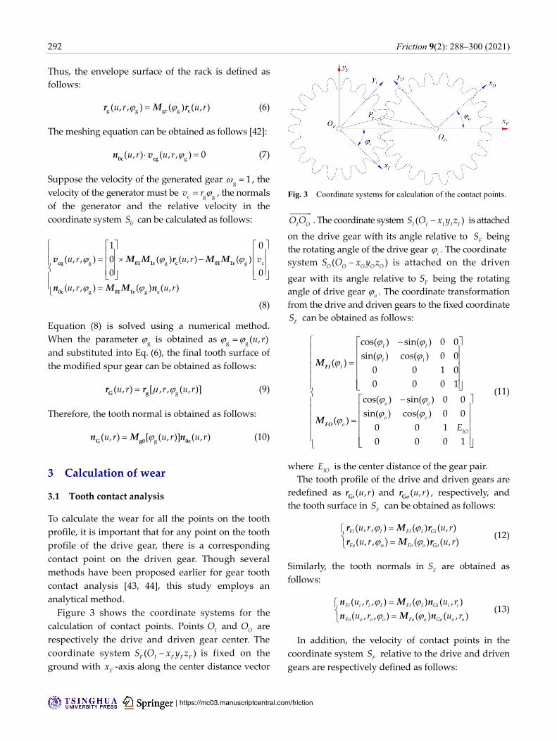
Figure 3 shows the coordinate systems for the
calculation of contact points. Points I
O and O
O are
respectively the drive and driven gear center. The
coordinate system ( )F I F F F
S O x y z is fixed on the
ground with F
x -axis along the center distance vector
Fig. 3 Coordinate systems for calculation of the contact points.
I O
O O . The coordinate system ( )I I I I I
S O x y z is attached
on the drive gear with its angle relative to F
S being
the rotating angle of the drive gear i. The coordinate
system ( )O O O O O
S O x y z is attached on the driven
gear with its angle relative to F
S being the rotating
angle of drive gear o. The coordinate transformation
from the drive and driven gears to the fixed coordinate
FS can be obtained as follows:
cos( ) sin( ) 0 0
sin( ) cos( ) 0 0( )
0 0 1 0
0 0 0 1
cos( ) sin( ) 0 0
sin( ) cos( ) 0 0( )
0 0 1
0 0 0 1
I I
I II
o o
o oo
IOE
FI
FO
M
M
(11)
where IO
E is the center distance of the gear pair.
The tooth profile of the drive and driven gears are
redefined as ( , )u rGi
r and ( , )u rGo
r , respectively, and
the tooth surface in F
S can be obtained as follows:
o
( , , ) ( ) ( , )
( , , ) ( ) ( , )Fi I FI I Gi
Fo Fo o Go
u r u r
u r u r
r M r
r M r (12)
Similarly, the tooth normals in F
S are obtained as
follows:
( , , ) ( ) ( , )
( , , ) ( ) ( , )Fi i i I FI I Gi i i
Fo o o o Fo o Go o o
u r u r
u r u r
n M n
n M n (13)
In addition, the velocity of contact points in the
coordinate system F
S relative to the drive and driven
gears are respectively defined as follows:
Friction 9(2): 288–300 (2021) 293
∣www.Springer.com/journal/40544 | Friction
http://friction.tsinghuajournals.com
0
( , , ) 0 ( , , )
1
0
( , , ) 0 ( , , )
/
i i I i i I
o o o o o I
o I
u r u r
u r u r
i Fi
o Fo
v r
v r
(14)
Further, the relative velocity of the contact points
between the drive and driven gears is obtained as
follows:
( , , , , , ) ( , , ) ( , , )i i o o I o i i I o o o
u r u r u r u r io i o
v v v (15)
Thus, for any conjugate point, including parameter
iu ,
ir in the drive gear and
ou ,
or in the driven gear,
the following conditions must be satisfied:
( , , ) ( , , )
( , , ) ( , , )
( , , ) ( , , , , , )
i i I i i I
i i I o o I
i i I i i o o I o
u r u r
u r u r
u r u r u r
= 0
Fi Fo
Fi Fo
Fi io
n n
r r
n v
(16)
This implies that for any point i
P ( ,i i
u u r r ) on the
tooth of the drive gear, the angular position of the
drive I, angular position of the driven gear
o, and
the contact point o
P ( , )o o
u u r r on the tooth of the
driven gear can be obtained.
For spur gears, the tooth surface can be simplified
as a planar curve. Therefore, the curvature of the drive
gear i
K and that of the driven gear o
K can be obtained
based on the planar curvature equation. The relative
curvature is defined as follows:
io i o
K K K (17)
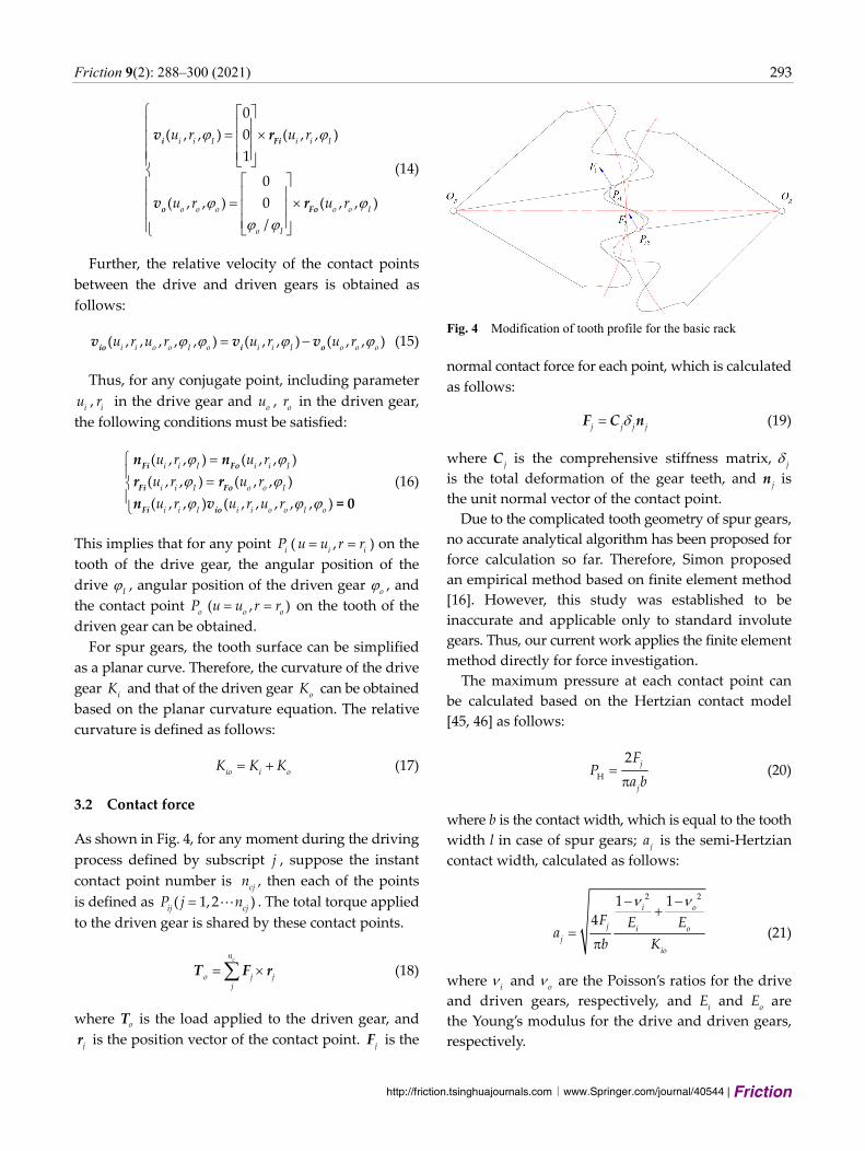
3.2 Contact force
As shown in Fig. 4, for any moment during the driving
process defined by subscript j , suppose the instant
contact point number is cj
n , then each of the points
is defined as ( 1,2 )ij cj
P j n . The total torque applied
to the driven gear is shared by these contact points.
cn
o j jj
Τ F r (18)
where oT is the load applied to the driven gear, and
jr is the position vector of the contact point.
jF is the
Fig. 4 Modification of tooth profile for the basic rack
normal contact force for each point, which is calculated
as follows:
j j j jF C n (19)
where j
C is the comprehensive stiffness matrix, j
is the total deformation of the gear teeth, and j
n is
the unit normal vector of the contact point.
Due to the complicated tooth geometry of spur gears,
no accurate analytical algorithm has been proposed for
force calculation so far. Therefore, Simon proposed
an empirical method based on finite element method
[16]. However, this study was established to be
inaccurate and applicable only to standard involute
gears. Thus, our current work applies the finite element
method directly for force investigation.
The maximum pressure at each contact point can
be calculated based on the Hertzian contact model
[45, 46] as follows:
H
2j
j
FP
a b
(20)
where b is the contact width, which is equal to the tooth
width l in case of spur gears; j
a is the semi-Hertzian
contact width, calculated as follows:
2 21 1
4i o
j i oj
io
F E Ea
b K
(21)
where i and
o are the Poisson’s ratios for the drive
and driven gears, respectively, and i
E and o
E are
the Young’s modulus for the drive and driven gears,
respectively.
294 Friction 9(2): 288–300 (2021)
| https://mc03.manuscriptcentral.com/friction
3.3 Wear depth calculation
Based on the generalized Archard’s wear equation [7],
the wear depth can be calculated as follows:
w H0d
s
h K P s (22)
where w
K is the wear coefficient, which is set to 16 25 10 m / N [15]. This equation can also be rewritten
differently as follows:
w H j 1i ih K P s h (23)
where i
s is the slider distance in each micro segment,
which can be obtained based on the point contact
features of the gear surface.
For drive gear:
| ( , , , , , )|
| ( , , )|i i o o I o
i j
i i I
u r u rs a
u r
io
i
v
v (24)
For driven gear:
| ( , , , , , )|
| ( , , )|i i o o I o
i j
o o o
u r u rs a
u r
io
o
v
v (25)
4 Example and discussion
4.1 Finite element analysis
As discussed earlier, the force applied to the gear contact
point is obtained through a finite element analysis in
the third commercial software ANSYS, and the wear
depth can be calculated based on the value of force.
In this research, the planet gear and sun gear of an
epicyclical transmission used in the wheel hub of an
electric automobile is considered as an example. The
basic parameters of the gear pair are shown in Table 1.
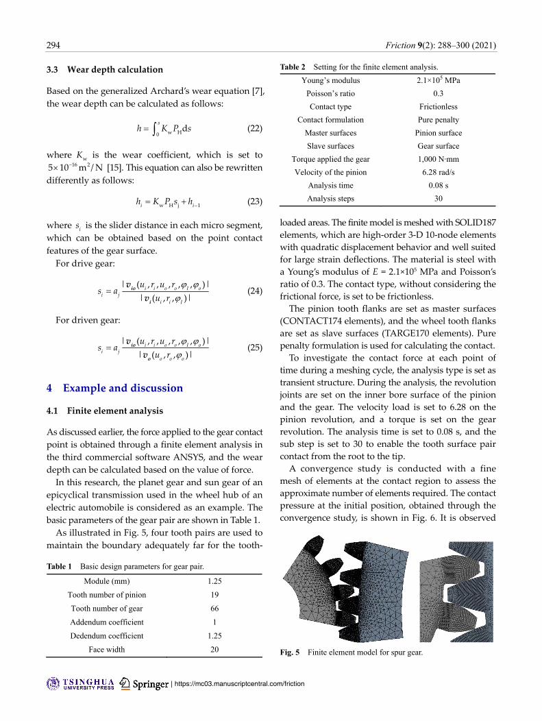
As illustrated in Fig. 5, four tooth pairs are used to
maintain the boundary adequately far for the tooth-
Table 1 Basic design parameters for gear pair.
Module (mm) 1.25
Tooth number of pinion 19
Tooth number of gear 66
Addendum coefficient 1
Dedendum coefficient 1.25
Face width 20
Table 2 Setting for the finite element analysis.
Young’s modulus 2.1×10⁵ MPa
Poisson’s ratio 0.3
Contact type Frictionless
Contact formulation Pure penalty
Master surfaces Pinion surface
Slave surfaces Gear surface
Torque applied the gear 1,000 N·mm
Velocity of the pinion 6.28 rad/s
Analysis time 0.08 s
Analysis steps 30
loaded areas. The finite model is meshed with SOLID187
elements, which are high-order 3-D 10-node elements
with quadratic displacement behavior and well suited
for large strain deflections. The material is steel with
a Young’s modulus of E = 2.1×10⁵ MPa and Poisson’s
ratio of 0.3. The contact type, without considering the
frictional force, is set to be frictionless.
The pinion tooth flanks are set as master surfaces
(CONTACT174 elements), and the wheel tooth flanks
are set as slave surfaces (TARGE170 elements). Pure
penalty formulation is used for calculating the contact.
To investigate the contact force at each point of
time during a meshing cycle, the analysis type is set as
transient structure. During the analysis, the revolution
joints are set on the inner bore surface of the pinion
and the gear. The velocity load is set to 6.28 on the
pinion revolution, and a torque is set on the gear
revolution. The analysis time is set to 0.08 s, and the
sub step is set to 30 to enable the tooth surface pair
contact from the root to the tip.
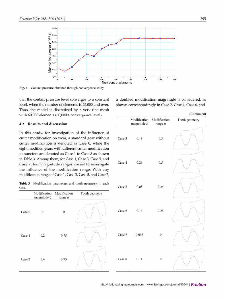
A convergence study is conducted with a fine
mesh of elements at the contact region to assess the
approximate number of elements required. The contact
pressure at the initial position, obtained through the
convergence study, is shown in Fig. 6. It is observed
Fig. 5 Finite element model for spur gear.
Friction 9(2): 288–300 (2021) 295
∣www.Springer.com/journal/40544 | Friction
http://friction.tsinghuajournals.com
that the contact pressure level converges to a constant
level, when the number of elements is 45,000 and over.
Thus, the model is discretized by a very fine mesh
with 60,000 elements (60,000 > convergence level).
4.2 Results and discussion
In this study, for investigation of the influence of
cutter modification on wear, a standard gear without
cutter modification is denoted as Case 0, while the
eight modified gears with different cutter modification
parameters are denoted as Case 1 to Case 8 as shown
in Table 3. Among them, for Case 1, Case 3, Case 5, and
Case 7, four magnitude ranges are set to investigate
the influence of the modification range. With any
modification range of Case 1, Case 3, Case 5, and Case 7,
Table 3 Modification parameters and tooth geometry in each case.
Modification magnitude ξ
Modification range μ
Tooth geometry
Case 0 0 0
Case 1 0.2 0.75
Case 2 0.4 0.75
a doubled modification magnitude is considered, as
shown correspondingly in Case 2, Case 4, Case 6, and
(Continued)
Modification magnitude ξ
Modification range μ
Tooth geometry
Case 3 0.13 0.5
Case 4 0.26 0.5
Case 5 0.08 0.25
Case 6 0.16 0.25
Case 7 0.055 0
Case 8 0.11 0
Fig. 6 Contact pressure obtained through convergence study.

296 Friction 9(2): 288–300 (2021)
| https://mc03.manuscriptcentral.com/friction
Case 8, to investigate the influence of modification
magnitude. It is worth noting that the influence of the
modification magnitude is different with different
modification ranges. Thus, the modifycation magnitude
should not be considered the same under different
modification ranges.
Varied tooth geometry against each case is also
shown in the table. The influence of the modification
parameters on the tooth shape can be deduced from
the tooth geometry. The modification range determines
the starting point of modification, and along with its
decrease, the modified tooth shows a higher deviation
from the standard tooth in Case 0. The modification
magnitude influences the deviation magnitude, and
along with its increase, the tooth tip and tooth root
decline.
Figure 7 shows the normal contact force at different
points in the gear. It is observed that the contact force
is not symmetrical without cutter modification (Case 0),
and it becomes relatively symmetrical with cutter
modification (Case 1–Case 8). In addition, the maximum
contact force is basically similar for all cases, implying
that the maximum contact force is not influenced
by cutter modification. However, the total contact
force is increases with an increase in either tooth
modification magnitude or modification range.
Figure 8 shows the semi contact width at different
points in the gear. It is observed that the curve shape
becomes symmetrical with cutter modification. In
addition, for Case 1–Case 8, the value of contact width
is almost the same at the middle tooth height point.
However, at other points, it is increased with an increase
in either modification magnitude or modification
range. This can be explained by the change of contact
force and relative curvature.
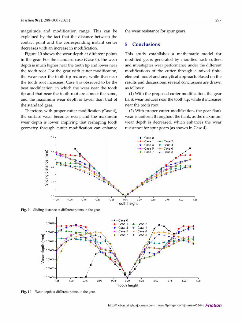
Figure 9 shows the sliding distance at different
points in the gear. It is observed that the sliding
distance decreases with an increase in the modification
Fig. 7 Normal contact force at different points in the gear.
Fig. 8 Semi contact width at different points in the gear.
Friction 9(2): 288–300 (2021) 297
∣www.Springer.com/journal/40544 | Friction
http://friction.tsinghuajournals.com
magnitude and modification range. This can be
explained by the fact that the distance between the
contact point and the corresponding instant center
decreases with an increase in modification.
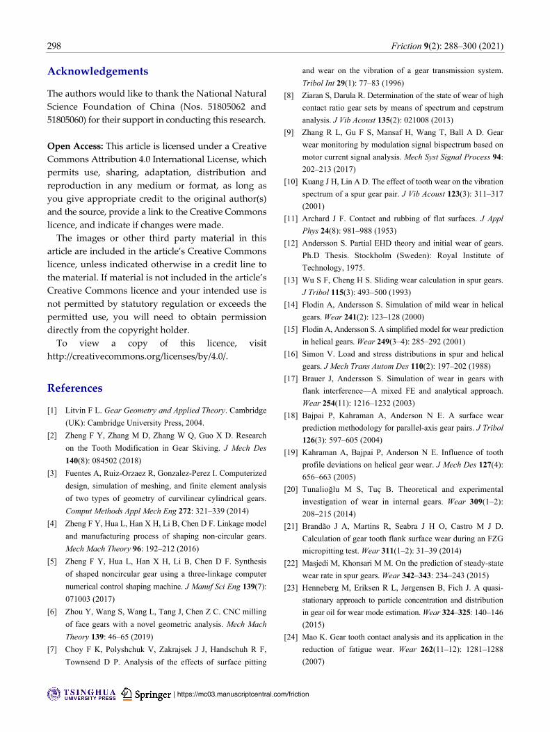
Figure 10 shows the wear depth at different points
in the gear. For the standard case (Case 0), the wear
depth is much higher near the tooth tip and lower near
the tooth root. For the gear with cutter modification,
the wear near the tooth tip reduces, while that near
the tooth root increases. Case 4 is observed to be the
best modification, in which the wear near the tooth
tip and that near the tooth root are almost the same,
and the maximum wear depth is lower than that of
the standard gear.
Therefore, with proper cutter modification (Case 4),
the surface wear becomes even, and the maximum
wear depth is lower, implying that reshaping tooth
geometry through cutter modification can enhance
the wear resistance for spur gears.
5 Conclusions
This study establishes a mathematic model for
modified gears generated by modified rack cutters
and investigates wear performance under the different
modifications of the cutter through a mixed finite
element model and analytical approach. Based on the
results and discussions, several conclusions are drawn
as follows:
(1) With the proposed cutter modification, the gear
flank wear reduces near the tooth tip, while it increases
near the tooth root.
(2) With proper cutter modification, the gear flank
wear is uniform throughout the flank, as the maximum
wear depth is decreased, which enhances the wear
resistance for spur gears (as shown in Case 4).
Fig. 9 Sliding distance at different points in the gear.
Fig. 10 Wear depth at different points in the gear.
298 Friction 9(2): 288–300 (2021)
| https://mc03.manuscriptcentral.com/friction
Acknowledgements
The authors would like to thank the National Natural
Science Foundation of China (Nos. 51805062 and
51805060) for their support in conducting this research.
Open Access: This article is licensed under a Creative
Commons Attribution 4.0 International License, which
permits use, sharing, adaptation, distribution and
reproduction in any medium or format, as long as
you give appropriate credit to the original author(s)
and the source, provide a link to the Creative Commons
licence, and indicate if changes were made.
The images or other third party material in this
article are included in the article’s Creative Commons
licence, unless indicated otherwise in a credit line to
the material. If material is not included in the article’s
Creative Commons licence and your intended use is
not permitted by statutory regulation or exceeds the
permitted use, you will need to obtain permission
directly from the copyright holder.
To view a copy of this licence, visit
http://creativecommons.org/licenses/by/4.0/.
References
[1] Litvin F L. Gear Geometry and Applied Theory. Cambridge
(UK): Cambridge University Press, 2004.
[2] Zheng F Y, Zhang M D, Zhang W Q, Guo X D. Research
on the Tooth Modification in Gear Skiving. J Mech Des
140(8): 084502 (2018)
[3] Fuentes A, Ruiz-Orzaez R, Gonzalez-Perez I. Computerized
design, simulation of meshing, and finite element analysis
of two types of geometry of curvilinear cylindrical gears.
Comput Methods Appl Mech Eng 272: 321–339 (2014)
[4] Zheng F Y, Hua L, Han X H, Li B, Chen D F. Linkage model
and manufacturing process of shaping non-circular gears.
Mech Mach Theory 96: 192–212 (2016)
[5] Zheng F Y, Hua L, Han X H, Li B, Chen D F. Synthesis
of shaped noncircular gear using a three-linkage computer
numerical control shaping machine. J Manuf Sci Eng 139(7):
071003 (2017)
[6] Zhou Y, Wang S, Wang L, Tang J, Chen Z C. CNC milling
of face gears with a novel geometric analysis. Mech Mach
Theory 139: 46–65 (2019)
[7] Choy F K, Polyshchuk V, Zakrajsek J J, Handschuh R F,
Townsend D P. Analysis of the effects of surface pitting
and wear on the vibration of a gear transmission system.
Tribol Int 29(1): 77–83 (1996)
[8] Ziaran S, Darula R. Determination of the state of wear of high
contact ratio gear sets by means of spectrum and cepstrum
analysis. J Vib Acoust 135(2): 021008 (2013)
[9] Zhang R L, Gu F S, Mansaf H, Wang T, Ball A D. Gear
wear monitoring by modulation signal bispectrum based on
motor current signal analysis. Mech Syst Signal Process 94:
202–213 (2017)
[10] Kuang J H, Lin A D. The effect of tooth wear on the vibration
spectrum of a spur gear pair. J Vib Acoust 123(3): 311–317
(2001)
[11] Archard J F. Contact and rubbing of flat surfaces. J Appl
Phys 24(8): 981–988 (1953)
[12] Andersson S. Partial EHD theory and initial wear of gears.
Ph.D Thesis. Stockholm (Sweden): Royal Institute of
Technology, 1975.
[13] Wu S F, Cheng H S. Sliding wear calculation in spur gears.
J Tribol 115(3): 493–500 (1993)
[14] Flodin A, Andersson S. Simulation of mild wear in helical
gears. Wear 241(2): 123–128 (2000)
[15] Flodin A, Andersson S. A simplified model for wear prediction
in helical gears. Wear 249(3–4): 285–292 (2001)
[16] Simon V. Load and stress distributions in spur and helical
gears. J Mech Trans Autom Des 110(2): 197–202 (1988)
[17] Brauer J, Andersson S. Simulation of wear in gears with
flank interference—A mixed FE and analytical approach.
Wear 254(11): 1216–1232 (2003)
[18] Bajpai P, Kahraman A, Anderson N E. A surface wear
prediction methodology for parallel-axis gear pairs. J Tribol
126(3): 597–605 (2004)
[19] Kahraman A, Bajpai P, Anderson N E. Influence of tooth
profile deviations on helical gear wear. J Mech Des 127(4):
656–663 (2005)
[20] Tunalioğlu M S, Tuç B. Theoretical and experimental
investigation of wear in internal gears. Wear 309(1–2):
208–215 (2014)
[21] Brandão J A, Martins R, Seabra J H O, Castro M J D.
Calculation of gear tooth flank surface wear during an FZG
micropitting test. Wear 311(1–2): 31–39 (2014)
[22] Masjedi M, Khonsari M M. On the prediction of steady-state
wear rate in spur gears. Wear 342–343: 234–243 (2015)
[23] Henneberg M, Eriksen R L, Jørgensen B, Fich J. A quasi-
stationary approach to particle concentration and distribution
in gear oil for wear mode estimation. Wear 324–325: 140–146
(2015)
[24] Mao K. Gear tooth contact analysis and its application in the
reduction of fatigue wear. Wear 262(11–12): 1281–1288
(2007)
Friction 9(2): 288–300 (2021) 299
∣www.Springer.com/journal/40544 | Friction
http://friction.tsinghuajournals.com
[25] İmrek H, Düzcükoğlu H. Relation between wear and tooth
width modification in spur gears. Wear 262(3–4): 390–394
(2007)
[26] Karpat F, Ekwaro-Osire S. Influence of tip relief modification
on the wear of spur gears with asymmetric teeth. Tribol
Trans 51(5): 581–588 (2008)
[27] Prabhu Sekar R, Sathishkumar R. Enhancement of wear
resistance on normal contact ratio spur gear pairs through
non-standard gears. Wear 380–381: 228–239 (2017)
[28] Prabhu Sekar R, Muthuveerappan G. A balanced maximum
fillet stresses on normal contact ratio spur gears to improve
the load carrying capacity through nonstandard gears. Mech
Based Des Struct Mach 43(2): 150–163 (2015)
[29] Zhou C J, Xiao Z L, Chen S Y, Han X. Normal and tangential
oil film stiffness of modified spur gear with non-Newtonian
elastohydrodynamic lubrication. Tribol Int 109: 319–327
(2017)
[30] Shih Y P, Chen S D. Free-form flank correction in helical
gear grinding using a five-axis computer numerical control
gear profile grinding machine. J Manuf Sci Eng 134(4):
041006 (2012)
[31] Zheng F Y, Hua L, Han X H. The mathematical model and
mechanical properties of variable center distance gears based
on screw theory. Mech Mach Theory 101: 116–139 (2016)
[32] Zheng F Y, Zhang M D, Zhang W Q, Tan R L, Guo X D. On
the deformed tooth contact analysis for forged bevel gear
modification. Mech Mach Theory 135: 192–207 (2019)
[33] Liu X Z, Yang Y H, Zhang J. Investigation on coupling
effects between surface wear and dynamics in a spur gear
system. Tribol Int 101: 383–394 (2016)
[34] Bouzakis K D, Kombogiannis S, Antoniadis A, Vidakis N.
Gear hobbing cutting process simulation and tool wear
prediction models. J Manuf Sci Eng 124(1): 42–51 (2002)
[35] Bouzakis K D, Friderikos O, Tsiafis I. FEM-supported
simulation of chip formation and flow in gear hobbing
of spur and helical gears. CIRP J Manuf Sci Technol 1(1):
18–26 (2008)
[36] Claudin C, Rech J. Development of a new rapid
characterization method of hob’s wear resistance in gear
manufacturing—Application to the evaluation of various
cutting edge preparations in high speed dry gear hobbing.
J Mater Process Technol 209(11): 5152–5160 (2009)
[37] Karpuschewski B, Beutner M, Köchig M, Härtling C.
Influence of the tool profile on the wear behaviour in gear
hobbing. CIRP J Manuf Sci Technol 18: 128–134 (2017)
[38] Jiang J K, Fan Z D. High-order tooth flank correction for a
helical gear on a six-axis CNC hob machine. Mech Mach
Theory 91: 227–237 (2015)
[39] Zheng F Y, Hua L, Chen D F, Han X H. Generation
of noncircular spiral bevel gears by face-milling method.
J Manuf Sci Eng 138(8): 081013 (2016)
[40] Zheng F Y, Hua L, Han X H, Chen D F. Generation of
noncircular bevel gears with free-form tooth profile and
curvilinear tooth lengthwise. J Mech Des 138(6): 064501
(2016)
[41] Li S T. Gear contact model and loaded tooth contact analysis
of a three-dimensional, thin-rimmed gear. J Mech Des 124(3):
511–517 (2002)
[42] Zhou Y, Wu Y, Wang L, Tang J, Ouyang H. A new
closed-form calculation of envelope surface for modeling
face gears. Mech Mach Theory 137: 211–226 (2019)
[43] Guan Y B, Fang Z D, Yang X H, Chen G D. Tooth contact
analysis of crown gear coupling with misalignment. Mech
Mach Theory 126: 295–311 (2018)
[44] Tran V T, Hsu R H, Tsay C B. Tooth contact analysis of
double-crowned involute helical pairs shaved by a crowning
mechanism with parallel shaving cutters. Mech Mach Theory
79: 198–216 (2014)
[45] Hu Z H, Ding H, Peng S D, Tang Y, Tang J Y. Numerical
determination to loaded tooth contact performances in
consideration of misalignment for the spiral bevel gears. Int
J Mech Sci 151: 343–355 (2019)
[46] Diez-Ibarbia A, Fernandez-del-Rincon A, De-Juan A,
Iglesias M, Garcia P, Viadero F. Frictional power losses on
spur gears with tip reliefs. The load sharing role. Mech Mach
Theory 112: 240–254 (2017)
Fangyan ZHENG. He received
his Ph.D. degree in School of
Automotive Engineering, Wuhan
University of Technology. His
current position is an associate professor in Wuhan
University of Technology. His research areas cover
the gear design, gear manufacturing, geometry,
mechanism, and so on.
300 Friction 9(2): 288–300 (2021)
| https://mc03.manuscriptcentral.com/friction
Jun ZHANG. He received the B.S.,
M.S., and Ph.D. degrees from
Tianjin University, China, in 2002,
2004, and 2007, respectively. He is
currently the deputy director of
Gear Lab, Fuzhou University, and
he is also a chair professor at the School of Mechanical
Engineering and Automation. He has published over
30 international journal papers and has served as a
reviewer of related journals for years. His research
interests include dynamic analysis, vibration control,
and fault diagnosis.
Ligang YAO. He received the B.S.
and M.S. degrees from Northeast
Petroleum University, China in
1984 and 1987, respectively, and
the Ph.D. degree from the Harbin
Institute of Technology, China in
1996. He is currently a professor at the School of
Mechanical Engineering and Automation of Fuzhou
University, China. His research focuses on the design
and manufacturing of innovative gear transmissions,
rehabilitation robotics, and geometric modeling.
Rulong TAN. He received his Ph.D.
degree in engineering from the
State Key Laboratory of Mechanical
Transmission, Chongqing University,
China, in 2016. Now, he is an associate professor in
Chongqing University of Technology. His research
interests include bevel gear geometry, kinematics,
and manufacturing.