Embed Size (px)
Citation preview
LUSACERL Tecnical Report FL-9326Seotmbri 1993
US Amy Corpsof En°"e" AD-A274 785Constucton Engineering
Investigation of RadiometricCombustion Monitoring Techniques forCoal-Fired Stoker BoilersbyFrederick V. KarlsonThomas H. ParsonsMartin J. SavoieWilliam B. Scholten
Fuel-ash bed disturbances are costly problems often en-countered in operating coal-fired, mechanical-stokerboilers In military heat plants. In traveling grate, me-chanical-stoker boilers, all or most of the coal bums onthe traveling grate, so proper control of combustion gratefuel-ash bed thickness is critical for cost-effective, high-availability operation. In these plants, operators must ad-just combustion equipment as the coal enters the coin-bustion chamber. Because fuel bed problems take sever-al minutes to develop, operators may not discover prob- ELECT Elems before they go past the point of easy correction. JAN 2 11994This study investigated the use of a remote sensingsystem to monitor conditions in the fuel bed. It is con- S'cluded that the technology to measure mechanical stokerboiler fuel-ash bed temperatures by radiation techniquesis sufficiently developed to produce a fuel-ash bed tem-peratures-monitoring system. Such a system may signifi-cantly reduce fuel-ash bed disturbances by detecting bedtemperature changes that indicate the onset of bedentrainment and clinker formation. Continuous, reliablemeasurement of fuel-ash bed temperatures could also 94-01816could be used to improve boiler efficiency throughimproved control of excess air.
Approed for public release; distribution is unlimited. 9 4 1 19 06 8

The contents of this report are not to be used for advertising, publication,or promotional purposes. Citation of trade names does not constitute anofficial endorsement or approval of the use of such commercial products.The findings of this report are not to be construed as an officialDepartment of the Army position, unless so designated by other authorizeddocuments.
DESTROY THIS REPORT WHEN IT IS NO LONGER NEEDED
DO NOT RETURN IT TO THE ORIGINATOR

[!REPR D OCUMENATION PAGE FnApw
PI~lb q blud.. hr Ur umbem. ed uduu b in.mlt a sl 11hw pwmam . umadig N~ m. fr am~ umbuams meadiag q dal mainP"mmaf *Am"ai m ft D .•ai•d. amn isba m ImM r U WI P udim.a.m SuOd omumad. qlmn Uran hd . exisimd aels sad Un.
ubia" "d udmurn, muh sgemul . far e.Amon Un hd. We"m" Hemeumahu S *, DImdkm ri uan W i Operefu.. m Io . 121.1idlm..D" 1# neg. Sld. 104, Aa ,n. VA , med ta 0 rnw Oims ed Mamalqmr& med udl. Pqepmwmek PAdmud.. Pqud (F70"4161. Wmswinw. DC M
1. AGENCY USE ONLY (Lawe BI*) 2. REPORT DATE E. EPORT TYPE AND DATES COVEREDSeptember 1993 7 Final
4. TITLE AND SUBTITLE 5. FUNDING NUMBERSInvestigation of Radiometric Combustion Monitoring Techniques for Coal-Fired IMIRStoker Boilers
S. AUTHOR(S)Fredrick V. Karlson, Thomas H. Parsons, Martin J. Savoie, and William B.Scholten
7. PERFORMING ORGANIZATION NAME(S) AND ADDRESS(ES) 8. PERFORMING ORGANIZATIONU.S. Army Construction Engineering Research Laboratories (USACERL) REPORT NUMBERP.O. Box 9005 TR-FE-93f26Champaign, IL 61826-9005
9. SPONSORING/MONITORING AGENCY NAME(S) AND ADDRESS(ES) 10. SPONSORINGOMONITORINGUSACERL Energy and Utility Systems Division (FE) AGENCY REPORT NUMBERP.O. Box 9005Champaign, IL 61826-9005
11. SUPPLEMENTARY NOTES
Copies are available from the National Technical Information Service, 5285 Port Royal Road, Springfield, VA22161.
12. DISTRIBUTIONIAVAILABILUTY STATEMENT 12b. DISTRIBUTION CODEApproved for public release; distribution is unlimited.
13. ABSTRACT (Maximum 200 words)
Fuel-ash bed disturbances are costly problems often encountered in operating coal-fired, mechanical-stokerboilers in military heat plants. In traveling grate, mechanical-stoker boilers, all or most of the coal burns on thetraveling grate, so proper control of combustion grate fuel-ash bed thickness is critical for cost-effective,high-availability operation. In these plants, operators must adjust combustion equipment as the coal enters thecombustion chamber. Because fuel bed problems take several minutes to develop, operators may not discoverproblems before they go past the point of easy correction.
This study investigated the use of a remote sensing system to monitor conditions in the fuel bed. It is concludedthat the technology to measure mechanical stoker boiler fuel-ash bed temperatures by radiation techniques issufficiently developed to produce a fuel-ash bed temperatures-monitoring system. Such a system may signifi-cantly reduce fuel-ash bed disturbances by detecting bed temperature changes that indicate the onset of bed en-trainment and clinker formation. Continuous, reliable measurement of fuel-ash bed temperatures could alsodetect smoking and conditions leading to smoking, and could be used to improve boiler efficiency throughimproved control of excess air.
14. SUBJECT TERMS 15. NUMBER OF PAGES
central heating plants radiometry 70coal-fired mechanical stoker boiler ,,combustion monitoring techniques 16. PRICE CODE
17. SECURITY CLASSIFICATION 18. SECURITY CLASSIFICATION 19. SECURITY CLASSIFICATION 20. LIMITATION OF ABSTRACTOF REPORT OF THIS PAGE OF ABSTRACTUnclassified Unclassified Unclassified SAR
NSN 7540-01-280-5500 Standard Form 298 (Rev. 2-89)PMw by AIl am ag-ISUS-l02

FOREWORD
This project was sponsored and conducted by the Energy and Utility Systems Division (FE),Infrastructure Laboratory (FL), U.S. Army Construction Engineering Research Laboratories (USACERL),under the Intra-Departmental Independent Research (IDIR) Program. The USACERL principalinvestigator was Martin J. Savoie. Frederick Karlson, Thomas Parsons, and William Scholten areassociated with the Science Applications International Corporation (SAIC). Dr. David M. Joncich is Chief,CECER-FE, and Dr. Michael J. O'Connor is Chief, CECER-FL. The USACERL technical editor wasWilliam J. Wolfe, Information Management Office.
LTC David J. Rebbein is Commander of USACERL and Dr. L.R. Shaffer is Technical Director.
/•cesion For
NTIS CRAMI •
DTIC TABU a:•nounced [J .Atfication ..... .
By ....................Dist;,ibution I
Availability Codes
Avail and I orDist Special
SI2

COWNTEMPage
SF 2% 1FOREWORD 2LIST OF FIGURES AND TABLES 4
1 INTRODUCTION ................................................... 5
ObjectivesApproachscopeMode of Technology Transfer
2 STOKER TECHNOLOGY ........................................... 8Coal-Fired Mechanical Stoker Boiler DescriptionThe ProblemPotential Fuel-Ash Bed Disturbance Solutions
3 MILITARY CENTRAL HEAT PLANT CONDITIONS ....................... 14Army and Air Force Central Heat Plant SurveyReference Spreader Stoker Furnace DefinitionAbility To Detect Conditions Leading to Fuel-Ash Bed EntrainmentPotential Nonmilitary Power and Heat Plant Applications
4 TECHNOLOGY STATUS REVIEW ...................................... 25Radiation OverviewRadiometry Status Review
5 GRATE FUEL-ASH BED TEMPERATURES MONITORING SYSTEM .......... 34Conceptual DesignTechnical CondusionsFuel-Ash Bed Temperatures Monitoring System Conceptual DesignFuel-Ash Bed Temperature Monitoring System Data Analysis and DisplayEstimated Order-of-Magnitude Fud-Ash Bed Temperature Monitoring System
Cost
6 CONCLUSIONS AND RECOMMENDATIONS ............................ 43CondusionsRecommendation
44REFERENCES 44
APPENDIX A: Technical Literature Survey 45APPENDIX B: Equipment Manufacturers Survey 61
DISTRIBUTION
3J

FIGURES
Number Par
1 Spreader Stoker Feeder-Distributor Mechanism 9
2 Spreader Stoker With Traveling Grate 10
3 View Inside of Stoker Front 12
4 Chain-Grate Stoker 12
6 Typical Military Heating Plant Spreader Stoker Unit (Nominal 70 MBtu/hroutput) 17
7 Severe Grate Pluggage 21
8 B&W's Fuel Quality Analyzer 23
9 Boiler Population Distribution 24
11 Blackbody Radiation at Various Temperatures 27
12 Blackbody Radiant Emittance vs. Wavelength 28
13 Emissivity Factors of Various Room-Temperature Surfaces 29
14 Spectral Transmission of the Atmosphere 30
15 Fuel-Ash Bed Temperature Conceptual Design 38
16 Typical Camera Automatic Retraction Mechanism 39
17 Proposed Fuel Ash Bed Temperatures Monitoring System Screen Display 41
TABLES
1 Reference Spreader Stoker Boiler Design As-Fired Coal Data 16
2 Wavelengths for Typical Fuel-Ash Bed Temperatures Assuming BlackbodyRadiation 19
3 Manufacturers' Information 32
4 Fuel-Ash Bed Temperatures Monitoring System General Performance Criteria 35
4

IvesTIGATION OF RADIOKM C COMBUSTION MONITORINGTECHNIQUES FOR COAL-FIRED STOKER DOILERS
1 INTRODUCTION
Baekgroumd
Fuel-ash bed disturbances-segregation, clinkering, uneven coal and ash bed-are costly problemsoften encountered in operating coal-fired, mechanical stoker boilers in military heat plants. In travelinggrate, mechanical stoker boilers (and hot water generators), all or most of coal combustion occurs on thetraveling grate. In these units, proper control of combustion grate fuel-ash bed thickness is critical forcost-effective, high-availability operation.
If portions of the fuel-ash bed become too thin or thick, undergrate combustion air flow distributionbecomes uneven. This condition can lead to clinkers in the thick areas of the bed, and blowholes in thethin areas, both of which will greatly increase particulate carryover and reduce boiler efficiency.Undergrate combustion air maldistribution, due to uneven combustion air flow, can also result in bedsolids entrainment, resulting in removal of all solids over a portion of a combustion grate. Fuel-ash bedsolids (coal, char, and/or ash) entrainment by undergrate combustion air, in addition to reducingcombustion efficiency, can reduce heat transfer and damage other furnace surfaces through erosion.Combustion grate surfaces exposed by fuel-ash bed loss can also suffer damage due to excessive heating.
Fuel bed disturbances depend on several factors, including equipment design, equipment condition,operator skill, and fuel quality. Of these factors, operntor skill and fuel quality are the most difficult tocontrol, and operator skill is highly dependent on the ability to respond to fuel-related problems.Operational difficulties originate from the nonhomogeneous nature of stoker coal. A particular coal'sability to completely combust in a stoker system depends on its physical and chemical makeup. Someof the most important stoker coal quality parameters are size distribution, ash fusion temperature, freeswell index, moisture content, and volatility. These parameters can vary widely among coals fromdifferent deliveries or different mines, and can also vary within a single delivery of coal, depending onhow it is handled or stored. Even though the coal is analyzed, it is difficult for heating plant personnelto visually distinguish these characteristics from one coal pile in the storage yard to another.
This uneven quality of different coals forces plant operators to adjust the combustion equipment asthe coal enters the combustion chamber. Because a fuel bed problem takes several minutes to develop,operators may not discover the problem before it has gone past the point of easy correction. Theidentification of fuel bed problems is very difficult for operators because of large furnace areas (typicallyover 100 sq ft)," and intense heat and light in the furnace bed. This situation could be greatly improvedby using a remote sensing (spectral imaging) system to monitor the fuel bed. A remote sensing systemwould improve operator response time to fuel distribution and other fuel-related problems. However,military and commercial applications of such monitors for stoker systems still need to be identified.
* I qft-0.093m'.
5

Objectves
The general objective of this study was to investigate the feasibility of developing a remote sensingsystem for monitoring the fuel bed of stoker-fired boilers.
Specific objectives were:
"* to assess current spectral imaging technologies (ultraviolet, visible, and infrared) to identifyapproaches for developing a commercial traveling grate, mechanical stoker, coal-fired boilerfuel-ash bed, monitoring system for use in military heat plants
"* to judge the most promising spectral imaging system for military heat plant applications, andto identify a fuel-ash bed monitoring system conceptual design
"* based on the fuel-ash bed monitoring system conceptual design, to create a development anddemonstration (D&D) plan and an estimated D&D cost range.
Approach
The following steps were taken to assess the applicability of spectral imaging technology to thestoker fuel-ash bed temperature monitoring problem:
I. Technical literature was reviewed.2. Spectral imaging equipment manufacturers were surveyed.3. Other research organizations were contacted.4. Sites were identified where commercially successful applications of the technology were already
in place.
To assess spectral imaging technologies, a reference 70 MBtu/hr spreader-stoker boiler wasspecified. Actual performance data and experience were used to estimate typical boiler conditions relevantto fuel-ash bed temperature monitoring, such as the temperature profile over the fuel-ash bed, andcombustion gas particulates concentration.
Of the two commercially successful applications similar to mechanical stoker boilers that werefound, one was used as a starting point to develop a conceptual design for a fuel-ash bed temperaturemonitoring system. A conceptual design for a fuel-ash bed monitoring system was developed using radia-tion-imaging technology. A method for interpreting the data from imaging radiation over an entire fuel-ash bed was proposed.
Scope
The results of this project are applicable to most coal-fired stoker systems. Radiometric monitoringmethods may also have applications for other fossil fuel-fired boilers and waste incinerators. Sincecombustion grate fuel-ash bed disturbance problems are most critical in the larger-scale (above 30 MBtu/hheat production) overfeed and spreader-feed, traveling grate stoker boilers currently used at military heatplants, this project concentrated on larger coal-fired systems. However, some of the findings of this studymay apply to other types of coal-fired mechanical stokers, such as spreader stokers with dumping grates.
6

Mode of Teehass•g Trmuaer
It is anticipated that the results of this study will lead to a Facilities Engineering Application Study(FEAP) demonstration of radiometric combustion monitoring techniques, and that the technology will bedetailed in FEAP bulletins and flyers.
7

2 STOKER TECHNOLOGY
Coal-fired boilers or hot water generators are frequently used to provide central heat (saturated steamor hot water) at DOD bases.* These boilers represent a wide range of designs, from underfeed stokers topulverized coal boilers. However, large boilers (those rated at 30 MBtu/h heat production) tend to useeither direct-feed or spreader-feed traveling grates for actual coal combustion. These boilers are normallyreferred to as "mechanical stoker boilers." A common problem associated with the designs of theseboilers is fuel-ash bed entrainment. Before defining the fuel-ash bed entrainment problem and ways toresolve it, a brief description of typical mechanical stoker boilers is needed.
Coal-Fired Mechanical Stoker Boiler Description
Mechanical stokers are devices that automatically feed coal into a boiler, and in some cases,automatically dispose of the ash. There are many types of mechanical stokers in use, each type differingin the way it feeds coal onto the combustion grate and how it removes ash from the grate. Mechanicalstokers can be divided into three categories based on how coal is fed onto the combustion grate:
1. Spreader stoker2. Overfeed stoker3. Underfeed stoker.
Within each category, stokers differ in how the grate handles ash.
A typical spreader-stoker boiler consists of a variable-feeding device, a mechanism for "throwing"coal into the boiler, and one or more grates, depending on capacity, with suitable openings for admittingcombustion air. The coal-feeding-and-distributing mechanism is located on the boiler front wall abovethe combustion grates.
The conventional mechanical spreader-stoker feeding-and-distributing device is arranged to supplycoal to the boiler grates in quantities required to meet demand. The feeder delivers coal to a revolvingrotor with protruding blades. These revolving blades direct the coal and "throw" it onto the boiler grates.The spreader system must be designed to distribute coal evenly over the entire grate area by the shape ofthe blades.
The spreader-stoker feeder varies the coal supply to the boiler and distributes the coal evenly ontothe grates. In a typical feeding-and-distributing system (Figure 1), there is a reciprocating feed platelocated at the bottom of a coal hopper. The length of stroke of this plate determines the rate the coal isfed into the boiler. The coal leaving the hopper drops from the end of the spilling plate into the path ofthe rotor blades, which then distribute coal onto the grates. Coal distribution is regulated by handadjustment of the spilling plate and by the rotor speed.
The in-and-out adjustment of the spilling plate changes the point where the coal contacts the rotorblades. Moving the spilling plate away from the boiler allows the coal to fall on the rotor blades sooner,so that the blades impart more energy to the coal, throwing it farther into the boiler. Similarly, increasingthe speed of the rotor also imparts more force to the coal.
"The term "boiler" will be used throughout this report to denote both boilers (steam producers) and hot water generators.
8

FEED
SPILLING -PLATEAOJUliN6•l~l~tll• •DEFLECTOR TUYI•RIS
APRN ruyiE•S
SPILLING ROTOR ROTOR AIR GMT TOPLATE HOUSING ROTOR MOUSING
Repnted with permission of McGraw-Hill, from E. Woodruffet al., Steam Plant Operation (1984), p 49.Figure 1. Spreader Stoker Feeder-Distributor Mechauism.
Figure 2 shows a typical traveling-grate spreader stoker boiler, in which ash is continuouslydischarged from the grates into an ashpit. The coal is thrown toward the rear of the boiler, and gratespeeds are adjusted to give sufficient time for complete combustion before the ash is discharged at thefront. When the grates are correctly adjusted, the process is continuous and there is no interference withboiler operation.
As coal is fed into the spreader-stoker furnace, some volatile matter and fine coal particles burn insuspension, and the remainder falls to the grate, where combustion continues. From 15 to 40 percent ofcombustion will take place in suspension before the co- ,,'aaches the coal bed. Pressure created by theforced-draft fan, forces air into the furnace through the openings in the grates. Part of this air is used toburn the thin layer of fuel on the grates, and the rest passes into the furnace where it burns the volatilematter and fine particles. The overfire air fan supplies additional air to the furnace through jets in thewall. This adds to the air supply for suspension burning and causes more turbulence than in on-grateburning (which occurs in underfeed and overfeed stokers).
Suspension burning causes more unburned carbon particles (cinders) to be carried out of the furnaceby the gases than in underfeed types. Some of these cinders collect in hoppers beneath the boiler'sconvection passes. However, a portion is retained in the exit boiler gases and must be intercepted by a
9

C OVERFIRE AIRcHPPR ( ..,...COAL HPE
H "] • • ". -".'","" " • OVERFIRE JFEE DER • -A""I." •R,' '' '
OVERTHROWROTOR AliR .' .. '.." " '.°. " ."
STOKER SEAL• AIR SEýAL
CHAIN " "'ASH HOPPER " i
AIR PLENUM
Reprinted with permission of the American Society of Heating, Refrigerating. and Air-Conditioning Engineers, Atlanta, GA, from the 1992ASHRAE Handbook-Systems ,nd Equipment, p 27.10.
Figure 2. Spreader Stoker With Traveling Grate.
fly-tash collector to prevent excessive pollution of the atmosphere. Since these particles contain carbon,returning the cinder to the furnace for reburning can improve the efficiency of steam generation.
Cinders are collected in the boiler, economizer, air heater, mechanical dust collector, and baghouseor precipitator hoppers. Cinders with the highest combustible content are deposited in the boiler hoppers,and those with the lowest in the baghouse or precipitator hoppers. The fine particles removed by thebaghouse or precipitator must be discarded to the ash-removal system. The baghouse or precipitator isrequired to reduce the particulate emission from the stack gases sufficiently to meet clean-air standards.
Suspension burning requires a supply of air directly to the furnace. This air is supplied by a high-pressure blower and enters the furnace through ports in the walls. These overfire air fans perform a triplefunction: they provide combustion air, create turbulence in the furnace, and reinject cinders from thecollection hoppers.
Even when spreader stokers are provided with controls to automatically regulate both the fuel feedand the air supply to meet the steam demand, the operator must attend to many details to obtain goodoperation. The spreader mechanism must be adjusted to distribute the coal evenly over the grates.Irregularities in the fuel bed caused by segregation of coal, wet coal, clinker formation, etc., must becorrected to maintain the fuel bed at sufficient thickness to sustain combustion for 2 to 3 minutes withthe fuel feed shut off.
10

The fuel-bed thickness may be changed by adjusting the ratio of fuel to air. An increase in the airpressure under the grates with the same fuel feed will decrease the thickness of the fuel bed; a decreasein air pressure will allow the fuel-bed thickness to increase. The overfire air must be regulated to obtainthe lowest amount of excess air (highest carbon dioxide) without permitting temperatures detrimental tothe furnace lining, clinkers in the fuel bed, or excessive smoke.
The modern spreader stoker installation consists of: (1) feeder-distributor units in widths andnumbers as required (Figure 3) to distribute the fuel uniformly over the width of the grate, (2) specificallydesigned air-metering grates, (3) forced draft fans for both undergrate and overfire air, (4) dust collectingand reinjecting equipment, and (5) combustion controls to coordinate fuel and air supply with loaddemand.
Unlike a spreader stoker, in operating an overfeed stoker, coal is gravity fed onto a grate from a coalhopper mounted on the front of the stoker. The depth of coal fed onto the grate is regulated by raisingand lowering a sliding coal gate at the hopper coal discharge (Figure 4). The coal bums as the gratetravels from one end of the boiler to the other. The ash is continuously deposited off the rear of the grateinto an ash pit.
Although not considered in this report, underfeed stokers have many useful applications. Underfeedstokers, developed in the 1800s, were very popular before World War II. However, after World War II,they were gradually replaced by larger spreader stokers and overfeed stokers.
The Problem
In coal-fired mechanical stoker boilers, proper control of combustion grate fuel-ash bed thicknessis critical. Undergrate combustion air maldistribution, due to uneven combustion air flow, can result inbed solids entrainment, resulting in the removal of all solids over a portion of a combustion grate. Fuel-ash bed solids entrainment by undergrate combustion air, in addition to reducing combustion efficiency,can result in damage to heat transfer and other furnace surfaces through erosion. Exposed combustiongrate surfaces can also suffer damage due to excessive heating. (The materials used in most combustiongrates cannot tolerate direct, prolonged exposure to furnace temperatures. The fuel-ash bed in most gratedesigns is used to insulate the combustion grate from prolonged exposure to maximum furnacetemperatures.) Riley Stoker Corporation estimates the budget price to replace a grate to be $190,000,excluding freight and taxes. This price is based on a 70 MBtu/hr spreader stoker-fired boiler requiringabout 92 to 100 sq ft of grate surface.
The basic concept behind the work associated with the investigation of optical combustionmonitoring technologies is to measure the radiation emitted from the fuel-ash bed of a mechanical stokercoal-fired boiler. The term "optical" is misleading since only a small fraction of the radiation emittedfrom fuel-ash beds is at visible wavelengths (0.4 to 0.7 micrometers). The technology measures radiationat ultraviolet (0.1 to 0.4 micrometers) and infrared (0.7 to 100 micrometers) wavelengths, as well as atvisible wavelengths. A number of terms are commonly used to describe radiation measurement and theinstruments for its measurement. In this report, the term radiometry is used to imply the science ofradiation detection and measurement at wavelengths from ultraviolet to infrared (synonymous terminologyincludes radiation thermometry and pyrometry). The actual class of instruments used to make radiationmeasurements are referred to as radiometers (synonymous terms include radiation thermometers,pyrometers, and IR thermometers).
11

Reprinted with permission of the Detroit Stoker Company, from Bulletin 85.
Figure 3. View Inside of Stoker Front.
DRIVE MCAIMSN
LINKAGE
SPROCKET
DRAG FRAME
Repritited with permission of the American Society of Hleating, Refrigerating, and Air-Conditioning Engineers. Atlanta, (;A, from the 1992ASHRAE Handbook- Sysiems and Equipment, p 27.11.
Figure 4. Chain-Grate Stoker.
12
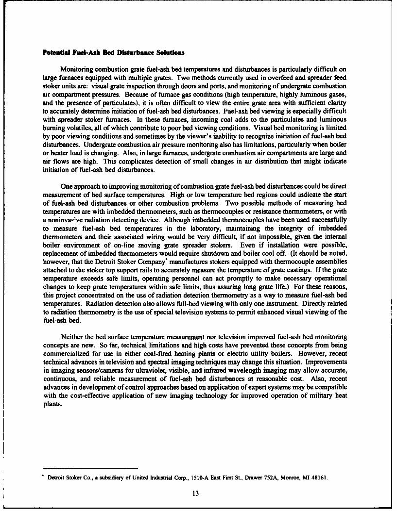
Potedtal Fuel-Ash Bed Disturbance Solutions
Monitoring combustion grate fuel-ash bed temperatures and disturbances is particularly difficult onlarge furnaces equipped with multiple grates. Two methods currently used in overfeed and spreader feedstoker units are: visual grate inspection through doors and ports, and monitoring of undergrate combustionair compartment pressures. Because of furnace gas conditions (high temperature, highly luminous gases,and the presence of particulates), it is often difficult to view the entire grate area with sufficient clarityto accurately determine initiation of fuel-ash bed disturbances. Fuel-ash bed viewing is especially difficultwith spreader stoker furnaces. In these furnaces, incoming coal adds to the particulates and luminousburning volatiles, all of which contribute to poor bed viewing conditions. Visual bed monitoring is limitedby poor viewing conditions and sometimes by the viewer's inability to recognize initiation of fuel-ash beddisturbances. Undergrate combustion air pressure monitoring also has limitations, particularly when boileror heater load is changing. Also, in large furnaces, undergrate combustion air compartments are large andair flows are high. This complicates detection of small changes in air distribution that might indicateinitiation of fuel-ash bed disturbances.
One approach to improving monitoring of combustion grate fuel-ash bed disturbances could be directmeasurement of bed surface temperatures. High or low temperature bed regions could indicate the startof fuel-ash bed disturbances or other combustion problems. Two possible methods of measuring bedtemperatures are with imbedded thermometers, such as thermocouples or resistance thermometers, or witha noninva--ve radiation detecting device. Although imbedded thermocouples have been used successfullyto measure fuel-ash bed temperatures in the laboratory, maintaining the integrity of imbeddedthermometers and their associated wiring would be very difficult, if not impossible, given the internalboiler environment of on-line moving grate spreader stokers. Even if installation were possible,replacement of imbedded thermometers would require shutdown and boiler cool off. (It should be noted,however, that the Detroit Stoker Company* manufactures stokers equipped with thermocouple assembliesattached to the stoker top support rails to accurately measure the temperature of grate castings. If the gratetemperature exceeds safe limits, operating personnel can act promptly to make necessary operationalchanges to keep grate temperatures within safe limits, thus assuring long grate life.) For these reasons,this project concentrated on the use of radiation detection thermometry as a way to measure fuel-ash bedtemperatures. Radiation detection also allows full-bed viewing with only one instrument. Directly relatedto radiation thermometry is the use of special television systems to permit enhanced visual viewing of thefuel-ash bed.
Neither the bed surface temperature measurement nor television improved fuel-ash bed monitoringconcepts are new. So far, technical limitations and high costs have prevented these concepts from beingcommercialized for use in either coal-fired heating plants or electric utility boilers. However, recenttechnical advances in television and spectral imaging techniques may change this situation. Improvementsin imaging sensors/cameras for ultraviolet, visible, and infrared wavelength imaging may allow accurate,continuous, and reliable measurement of fuel-ash bed disturbances at reasonable cost. Also, recentadvances in development of control approaches based on application of expert systems may be compatiblewith the cost-effective application of new imaging technology for improved operation of military heatplants.
"Detroit Stoker Co., a subsidiary of United Industrial Corp., 1510-A East First St., Drawer 752A, Monroe, M! 48161.
13

3 MILITARY CENTRAL HEAT PLANT CONDITIONS
Army and Air Force Central Heat Plant Survey
As a part of the Army's coal Conversion Program, USACERL maintains a data base of informationon all Army and Air Force boilers. A capacity survey was done from this data base of the coal-firedboilers installed at military central heating plants. The inventory of military coal-fired boilers shows 126units in the 20 to 400 MBtu/h output range, of which 27 are rated at 40 MBtu/h or less. Five units werefound to have ratings between 10 and 20 MBtu/h. These results are summarized in Figure 5.
Reference Spreader Stoker Furnace Definition
A well-defined reference boiler will help explain the causes of fuel-ash bed entrainment inmechanical stoker boilers and potential problems associated with bed temperature monitoring. Thisreference boiler is meant to represent a "typical" military heat plant mechanical stoker boiler that wouldbe a candidate for the installation of a fuel-ash bed temperature monitoring system. A spreader stokerboiler of the type described in Chapter 2 was selected for the following reasons:
1. This boiler type is judged to be the most difficult type for fuel-ash bed temperaturesmeasurement because of the manner of coal feeding. In spreader stokers, coal is flung over the grates withthe finer particles burning in suspension above the grates. The combination of unignited coal particlesand burning coal particles obscures the grate surface and the fuel-ash bed from view. If a radiometer canview the fuel-ash bed of a spreader stoker, it can very likely view that of an overfeed traveling gratefurnace.
2. Spreader stoker boilers range in capacity from 5 to 180 MBtu/h of heat generation, a range thatincludes 61 units in the military inventory. These units would likely profit most from a fuel-ash bedentrainment and combustion air maldistribution control system.
3. Reportedly, large spreader stoker furnaces experience fuel-ash bed entrainment problems morefrequently than other traveling grate mechanical stoker boilers.
Table 1 presents the as-fired coal specified for the reference spreader stoker boiler. To establishboiler maximum continuous rating, the following conditions were used to calculate boiler thermalefficiency:
* 25 wt. percent of the coal feed burns in suspension (does not reach the combustion grate)* fly ash carbon concentration: 50 wt. percent* bottom ash (grate discharge) carbon concentration: 10 wt. percent* stack flue gas exit temperature: 450 "F0 design excess air: 40 wt. percent* boiler external surfaces radiation loss: 0.90 percent• unaccounted for loss: 1.50 percent.
Calculated boiler thermal efficiency is 79.7 percent. This translates to a design coal feed rate of87.8 MBtu/h or 3.4 t/h.
OF = (OC x 1.8) + 32.
14

lgj
100
V- asn
J~urLN
Isy.

Table I
Reference Speder Stoker BelerDesig As-Fred Col Data
COmP.MeRVIPer ty" Value
Volatile matter 38.0Fixed carbon 48.0Free swelling index 5.0Ash fusion tempemrure
(hemispherical) 2200 *F (oxidizing)
C 72.0 wt%H2 4.4 wr/oS 1.6 wt%02 3.6 wt%/
N2 1.4 wt*/H'0 8.0 wv%Ash 9.0 wt%
100.00Higher heating value
size distribution: 12,000 Btu/Ib+1-1/4 in.1-1/4 - 3/4 in. 5 wt%3/4 - 1/2 in. 10 wt%1/2 - I/4 in 35 wtV.1/3 in. - 8 mesh 30 wt%-8 mesh Is wt%/
5 wt°/o
Based on this data, a reference spreader stoker having a design generation capacity (maximumcontinuous rating) of 70 MBtu/h of steam was specified for use in this study. This reference boiler wasused to keep in perspective the general dimensions and conditions that would be encountered inmonitoring fuel-ash bed temperatures in military heat plant mechanical stoker boilers. However, inevaluating competing radiometry techniques and development of a temperature measurement systemconceptual design, the complete range of military mechanical stoker boilers that could be candidates forfuel-ash bed temperatures measurement was considered, including spreader stokers employing multiplefeeder-distributor mechanisms (Figure 3).
To estimate approximate reference boiler dimensions, the following parameters were estimated fromspreader stoker boiler design data:
"• grate length-tm -wvdth ratio: 1.2"* boiler furnace heat release rate: 30,000 Btu/sq ft-h"* coal feed rating: 50 lb/sc f-h (This rate was applied based on the coal feed rate unadjusted
for coal combusted above the boiler grate.)
Basic dimensions for the reference spreader stoker boiler are shown in Figure 6. The effective gratelength is 12.8 ft; grate width is 10.7 ft; and, furnace internal height is 21.4 ft. One possible applicationof a radiometer(s) to continuous, on-line measurement of grate fuel-ash bed temperatures for a boiler ofthe type illustrated in Figure 6 is to mount the radiometer(s) on a furnace wall or roof to view the entirefuel-ash bed area. The lens of the radiometer would actually iook through a small penetration in thefurnace wall or roof.
16

(Grate Width: 10.7 ff.)
12.8 ft.Coal
so 21.4 ft.41 LocationCoalFeeder - Mean Free PathSpreader ~*:
Ash
Burnut Euifturn Non-quiltiu
se I
Figure 6. TypWca Miltary Heating plant Spreader Stoker Unit (Nominal 70 MBtu/hr Output)
17

There are four areas of critical importance to determining the feasibility of using a radiometer tomeasure grate fuel-ash bed temperatures (measurement of temperatures over the entire grate area) in aboiler of the type illustrated in Figure 6:
1. Fuel-ash bed temperatures and how these change over the bed
2. Boiler combustion, gases, particulate (entrained ash, coal, and falling feed coal) concentrationand size distributions
3. Combustion gases temperatures (particularly in the lower portion of the boiler) and radiation
characteristics
4. Boiler wall temperatures and emissivities.
To estimate "typical" fuel-ash bed temperatures, actual measurements for spreader stoker boilersreported in a British paper were used (Marshall and Pratt 1952). Estimated fuel-ash bed temperatures arepresented as isotherms at the bottom of Figure 6. All fuel-ash bed temperature data located to date havebeen in the form presented in Figure 6, that is, the temperatures have been measured through the fuel-ashbed (temperature versus ash depth), rather than across the bed surface. (Note that coal bed depthstypically range from 6 to 9 in.)" These values represent temperatures in the main portion of the fuel-ashbed. Some distortion of these temperature profiles undoubtedly occurs as the boiler side walls areapproached. No data to estimate side wall effects were located. However, these effects obviously dependon the amount of fouling on the walls.
Both British and U.S. researchers (Marckell, Miller, and Joyce 1952; Carman, Graf, and Corey 1959)have simulated traveling grate combustion using static "pot" type combustors. In these tests, time is usedto simulate grate movement. Results from the static tests generally agree with the temperature profilespresented in Figure 6 for a bituminous coal of the quality shown in Table 2 (a good quality spreaderstoker boiler coal). This data also clearly demonstrates that coal quality and rank can significantly affectfuel-ash bed temperature profiles. Specific coal quality parameters that significantly affect fuel-ash bedtemperatures are: ash concentration, ash form (extraneous versus disseminated), ash fusion temperature,volatile matter concentration, and moisture concentration. As a further check on the estimated spreaderstoker fuel-ash bed temperature profiles, Figure 6 and Table 2 were provided to Babcock & Wilcox's(B&W's)" combustion engineers, who concluded that the Figure 6 profiles appear reasonable, but that theycould not comment further without running a boiler design model (Estimation of Fuel Use and Populationfor Industrial Boilers 1985).
Estimates of furnace particulates concentrations in the zones relevant to fuel-ash bed viewingindicate that the mean distance between particles (mean free path) over the fuel-ash bed (see Figure 6) islarge compared with the wavelengths at which radiometers operate. The estimated mean particulatesvolume concentration in the boiler combustion gas is less than 0.001 percent of the total boiler internalvolume. As a result, attenuation of bed radiation by particulates is not currently judged to be a seriousproblem. It is more likely that particulates would occasionally and very briefly, block emitted radiationfrom reaching a scanning radiometer. Such blocking can be handled by short-term averaging of radiationintensity.
"I in. =25.4 mum."- Babcock & Wilcox, Power Generation Group, PO Box 351, Barberton, OH 44203, tel. 1-800-354-4400.
18

T • 2
Wa"kagft for Tyu Fmu-Ash OWTeupnramres Aumumil 3lchbl e Rafdsn
Tempedrare Temperlmr hul FmbeuimCF) (IC) Wayuuq Mkremtsm
3000 1922 1.5
2000 1366 2.1
1000 811 3.6
500 533 5.4
A potential particulate problem is smoke. Excess smoke could significantly attenuate fuel-ash bedradiation. However, since a properly operating spreader stoker boiler does not produce smoke, presenceof high smoke concentration is assumed to be due to a boiler upset. In fact, a radiometer may be betterable than other methods to detect smoke conditions earlier and at low concentrations. This could be a sidebenefit of using a radiometric system for controlling fuel-ash bed entrainment.
Ability To Dete~t Conditiem Leading to Fuel-Ash Bed Entrainment
Measurement of fuel-ash bed temperatures can only reduce costs if this information can help toeliminate or significantly reduce bed entrainment incidents. In other words, this assumes that irregularfuel-ash bed temperatures either cause, or are associated with, bed entrainment. This assumption wascomplicated by the fact that no thoroughly documented descriptions of bed entrainment were located. Theonly information available was the experience of USACERL and contract support engineers.
From knowledge of the combustion processes associated with traveling grates, two phenomena werepostulated to be likely causes of fuel-ash bed entrainment: combustion air thermal choking and clinkerformation. The concept of combustion air thermal choking was postulated from a review of the Britishand U.S. static "pot" type combustion tests used to confirm the Figure 6 bed temperature profiles. Theterm thermal choking was coined to identify this phenomena. Whether or not other terms are used todescribe this phenomena is not known.
The British static test data clearly show that localized high grate temperatures result in reduced airmass flow rate through the higher temperature grate area. A graph of both grate temperature and air rate(Figure 6) "shows a rise in grate temperature caused by the burning bed immediately above. This, in turn,by causing an expansion of air passing through the grate, reduces the mass flow. As a shielding ash layerdevelops on the grate, the grate temperature falls and the air supply increases. Thus, although there areno compartments under the grate and the under-grate air pressure is constant, there is a varying air supplyalong the grate length."
The British paper describing the static "pot" type combustion testing states that "fuel beds of depthsup to 4 in. have little resistance compared with the grate resistance unless abnormal packing or clinkeringoccurs." This implies that, within limits, thinning of the fuel-ash bed by itself may not be a cause of ashand/or coal entrainment. Such thinning, however, could result in abnormally high grate temperatures.
19

Researchers from the U.S. Bureau of Mines (Carman, Graf, and Corey 1957) used a pot combustionchamber similar to that employed by the British. They also observed "unexpected" variations in bed airflow rate over the combustion grate. Calculations based on estimated gas analysis and bed temperaturesshowed this variation was due to an "increase in volume and viscosity of the gases with temperature."
Thermal choking is postulated to occur when a significant fraction of the combustion grate areabecomes hotter than the remaining grate area. This diverts excess combustion air through the cooler gratearea. When the gas velocity associated with excess air flow diversion reaches a certain level, it entrainsthe fuel-ash bed over the cooler grate area. Exposure of additional grate area to boiler radiation couldexpand the fraction of grate area at abnormally high temperature and possibly exacerbate air diversion(maldistribution) and bed entrainment. Note that, although grate combustion air thermal choking is apostulated cause of bed entrainment, it has not actually been proven to cause bed entrainment.
If combustion air thermal choking is a real phenomena and a significant cause of fuel-ash bedentrainment, the onset of conditions that lead to it should be detectable by bed temperatures monitoring.If grate temperatures are abnormally high, fuel-ash bed surface temperatures would also be abnormallyhigh over a similar area. The development of abnormally high bed temperature areas probably has a timeconstant sufficiently large to allow corrective action before bed entrainment. However, this time constant,and the existence of thermal choking, must be determined by actual testing on a mechanical stoker boiler.
Fuel-ash bed clinkers form when molten ash particles agglomerate and harden as they cool. Clinkers(or a clinker of sufficient size) will impede air flow through the fuel-ash bed and/or plug grate airopenings (Figure 7). Blinding of a portion of the grate can result in excess gas velocities over otherportions of the grate. If these velocities become high, they will entrain bed material. Since clinkeringis associated with high fuel-ash bed surface temperatures for a properly specified coal, its onset shouldalso be detectable by bed temperatures monitoring.
Another possible cause of fuel-ash bed entrainment is oversupply of combustion air. On somestokers, there may be a problem with high pressures if the resulting turbulence lifts particulate matter offthe grate. If this does happen, the overfire air pressures should be reduced. However, in most units theavailable fan capacity is usually, by design, not sufficient to result in bed entrainment. If air oversupplyis a cause of bed entrainment and it does not develop suddenly (such as by rapid full opening of adamper), it will result in abnormal bed temperatures, which would be detectable by a temperaturemonitoring system.
Other conditions leading to the onset of bed entrainment and reduced combustion efficiency are:
"* segregation"* uneven coal bed"* uneven ash bed"* uneven burning"* smoking.
These and other conditions are sensitive both to operating conditions and the quality of coal being burned.Key operating conditions that can be adjusted to improve combustion include:
* zone dampers* overfire air• coal feeders* furnace pressure* grate speed.
20

Figure 7. Severe Grate Pluggage.
Not burning a properly specified coal can also reduce efficiency and increase maintenance. Someof the key coal parameters that can affect combustion efficiency are:
" Size distribution - For spreader stokers, it is not only important to have the correct top andbottom size, but it is just as important to have a proper distribution between the top and bottomsizes. As coal is distributed onto the fuel bed, the larger coal lands toward the back, whilesmaller particles land near the front of the grate. If a certain size is missing, holes will formin the fuel bed. More of the combustion air will follow this path of least resistance, causingcombustion problems elsewhere on the fuel bed.
" Fines - Excessive fines will magnify coal segregation problems. If there are too many fines,segregation will increase every time the coal is handled or stored. Coal segregation in thestoker feeder system leads to problems with incomplete combustion on the grate. Fine coalpiles do not allow the underfire air to penetrate the bed and can lead to clinker formation andhigh grate temperatures. High grate temperatures will damage the grate and increasemaintenance costs.
" Free Swelling Index - A high swelling coal can hamper ignition in two ways. If ignition isaccomplished by means of an arch, it is very important that the coal have a high volatile mattercontent and that enough combustion air moves through the coal bed to enhance combustion.If the coal swells too much, the underfire air is cut off and the flame "walks" away from thearch. When this condition occurs throughout the fuel bed, it is called agglomeration, whichcauses smoking and can result in the formation of large clinkers. If the coal contains a largeamount of fines, the swelling will be more severe.
21

" Ash Fusion Temperatures - Clinkers are formed when the temperature on the grate exceeds thehemispherical temperature of the ash. The grate holes can become plugged and the underfireair is cut off (Figure 7), increasing carbon losses and decreasing combustion efficiency. If toomany of these holes are plugged, the air velocity will increase through the remaining openingholes, which could increase the amount of particulates exiting the furnace chamber.
" Ash - It is important to have enough ash to insulate and protect the grate from the extremetemperatures within the combustion zone. It is also important to acquire coal that does not havetoo much ash. Excessive ash will increase equipment wear and handling costs. It will alsolower the heating value, which will increase the amount of coal required to satisfy the same loadrequirement. The added coal will increase the amount of ash even further. There will be anotable loss in efficiency due to the increased ash content.
While not exhaustive, this list serves to illustrate the consequences of firing incorrectly specifiedcoal. Incorrect size, free swelling index, ash fusion temperature, or ash content can cause poor combustionair distribution in the fuel bed. Improper air distribution will allow air to bypass the fuel and go directlyout the stack, requiring more air to be used to burn the fuel. High excess air can carry unburned fuel outof the furnace. When combustion air cannot pass through the coal, the coal will not bum completely, mayform clinkers, and will be discharged into the ash system.
This study was mainly directed at eliminating or significantly reducing fuel-ash bed entrainment.However, there appear to be at least two other benefits that could result from accurate, reliable, continuousmeasurement of fuel-ash bed temperatures: control of smoking and of excess air. Smoking, which isrelated to excess air control, is an undesirable situation for both efficiency and environmental reasons.Smoke would likely reduce the radiation observed by a radiometer sufficiently to allow rapid, cleardetection. Orsat-type CO and 02 monitors used in conjunction with an IR system to control smoking andexcess air, could be an added benefit to detecting opacity and improving boiler efficiency.
The concept of controlling excess air by fuel-ash bed temperatures monitoring was suggested byB&W, which has developed a radiometric technique using an online, continuous flame quality analyzerfor use in utility-scale boilers (see Figure 8). This analyzer measures both the intensity and temperatureof burner flames. In a series of tests on an oil-fired package boiler, the flame temperatures measured bythis analyzer were found to correlate with burner excess air. Based on this experience and their generalboiler design expertise, B&W judged that there is a reasonable chance that moving bed grate surfacetemperatures could also correlate with combustion excess air. If excess air control by bed temperaturesmonitoring could be demonstrated, it would likely be of much greater economic value than bedentrainment control since excess air control is a major determiner of boiler efficiency.
Potential Nonmilitary Power and Heat Plant Applications
Stokers, specifically spreader and overfeed stokers, have many useful applications and are still beingused today. These applications are widespread throughout many manufacturing industries, such as:
"* food o printing"* tobacco • chemicals"* textiles • petroleum"* apparel • rubber"* lumber • leather"• furniture a stone"* paper • machinery.
22

PROs
OPTIC"OYIAI
Ou"
Repinted with permission of Helmers Publishing. Inc., ftom Sensors: The Journal of Machine Percepdon, Vol 5, no. I (Januay 1985).
Figure 8. B&W's Fuel Quality Analyzer.
In 1985, there were approximately 2287 spreader stokers and 1200 overfeed stokers in usethroughout these industries. These stokers ranged in capacity from less than 10 MBtu/hr to more than 500MBtu/hr. Figure 9 shows a population distribution of the number and capacity ranges for these two stokertypes and is based on information derived from a report prepared for the Burns and Roe ServicesCompany (PEI Associates 1985). The figure alsu shows that there were approximately 427 spreaderstokers and 308 overfeed stokers in the 50 to 99 MBtu/hr capacity range. Furthermore, there wereapproximately 16 spreader stokers and 5 underfeed stokers with a capacity greater than 500 MBtu/hr. Thisinformation implies that the monitoring system being addressed in this report could have widespreadapplications to many other industries.
23

Coa,-Fid Wawr-Tub AlmngO0
7796
6316
700-
600 - $66
500o
J400
31630300
200 0
I0 -241 1 9
05 7 W29756 2
0 I- 0 10-24 24-49 so-99 0-249 250 -7 4
Spedr OM Owmb~d Sloem
Number of UnitsCapacity Range Mean Capacity
(Mlstalbr) (Mite/br) Water-Tube Water-TubeSpreader Stokers Overfeed Stokers
0-10 5 72 9310-24 17 316 19725- 49 27 566 42950-99 74 427 308
100- 249 174 796 139250 - 499 374 94 29
> 500 16 5
Total 2287 1200
Figure 9. Boiler Population Distribution.
24

4 TECHNOLOGY STATUS REVIEW
Radlation Overview
Whenever an electric charge undergoes acceleration, an electromagnetic wave is formed that sendsenergy through space or other medium--air, gases, liquids, or solids-in somewhat the same way as wavesspread out over the water when a stone is dropped into a pond. These electromagnetic waves are referredto as radiation.
Electromagnetic waves are called radio waves when they vibrate slowly enough to cause a responsein a radio transmitter. They may be generated when electrons move up and down in the tower of atransmitting antenna. Electromagnetic waves of various high frequency ranges (Figure 10) are known byother names: heat, infrared radiation, visible light, ultraviolet light, x-rays, and gamma rays.
Combustion Radiation Spectrum
In solids such as coal, it is far more commonly the vibratory motion of electrically charged particles(ions) that give rise to the electromagnetic radiation referred to as infrared radiation. Every body radiatesnot just one type of radiation, but some of each. For example, a white-hot piece of coal in a fireplace(Figure 11) generates the most intense radiation in the infrared (IR) region, with some visible light anda small amount of ultraviolet (UV) radiation (too weak to be seen on the graph).
The three commonly used divisions of the IR spectrum are:
"* the near-IR region, from approximately 0.7 to 1.5 micrometer-"* the intermediate- or middle-IR region, from approximately 1.5 to 5.6 micrometers"* the far-IR region from approximately 5.6 to 1000 micrometers.
Blackbody Radiation
A blackbody is any object that completely absorbs all radiation incident upon it. Conversely, theradiation emitted by a blackbody at any given temperature is the maximum possible. A blackbody istherefore an idealized or perfect absorber and radiator of radiation, at all temperatures and for allwavelengths. Its radiating and absorbing efficiency, called its emissivity factor, is said to be "unity."
Any object, blackbody or otherwise, whose temperature is above absolute zero radiates energythroughout the IR spectrum. The amount and spectral characteristics of the IR energy radiated dependon the absolute temperature of the object, and also on its nature and surface finish. A highly polishedsurface such as a silver- or aluminum-surfaced mirror is an extremely poor radiator and absorber ofenergy; its emissivity factor is close to zero. A black, rough surface is a highly efficient absorber andradiator of energy; its emissivity factor is close to unity. Objects with emissivity factors less than unityare termed "graybodies," and the great majority of objects encountered in practice fall into this category.
The absolute temperature of the radiating object, the wavelength of the peak radiation emitted, theshape of the radiation intensity versus wavelength curve, are related by the following fundamental lawsof physics:
* Planck's Law, which states that the intensity of radiation (referred to as spectral radiantemittance) associated with a blackbody is emitted or absorbed within a narrow band offrequencies in amounts that are proportional to the frequency of radiation and the temperature
25

iiin
NA T
1 1
9 be
aca
26U

169 W/m 2 -nm I-L-f
140"C .. 4.22
510
1013 1014 iP Vir 1015requency, Hz
Figure from College Pia~s by Fredrick A. Saunders and Paul Kirkpeack, copyrightC 1982 by Saunders College Publishing, reproduced by
permission of the publisher.
Figure 11. Blackbody Radiation at Various Temperatures.
of the body. Figure 12 shows the spectral radiant emittance for blackbodies at various absolutetemperatures. Note that, as the temperature of the blackbody increases, the intensity of theradiant energy emitted increases rapidly.
" Wein's Displacement Law, which states that the wavelength of peak radiance multiplied by theabsolute temperature of the blackbody is equal to a constant. Figure 12 shows that as thetemperature of a blackbody increases, its radiation peak shifts to shorter wavelengths.
" Stefan-Boltzmann Law, which states that the total energy radiated by a blackbody isproportional to the fourth power of the temperature of the body.
27

x.. re zL890 x io'Im KI01T 2S. \0.
2000 K
10' 10
'0102. \K
30Joe.~
10 1,.",
!0!
10-10
I I I I I I I I
0.1o.. o., o 4 loo
Wwamnqth (MelP
Figure 12. Blackbody Radiant Emittance vs. Wavelength.
Emnissivity and Reflectance
The above laws all apply to blackbodies with an emissivity of 1.0. However, most bodiesencountered in practice are not perfect blackbodies, but are graybodies, which radiate or absorb less thana blackbody would at the same temperature. Their emissivity is always less than unity (1.0).
The emissivity factor of an object is a measure of its radiation (and absorbing) efficiency. It isdefined as the ratio of the radiation emitted by a graybody to the radiation emitted by a perfect blackbodyat the same temperature. Graybodies do not therefore obey the laws governing a blackbody. The abovelaws must be amended by multiplying them by the emissivity factor, which therefore indicates thegrayness of the radiating body. The lower the emissivity factor, the grayer the body; the higher the factor(the nearer it approaches to unity) the blacker the body.
28

Not all sources behave like graybodies. The emissivity on some surfaces varies with thewavelength. The wide range of emissivity factors for different types of commonly encountered low-temperature sources is illustrated in Figure 13.
Radiation Absorption by Combustion Gases
IR radiation emitted by the primary source (of radiation) and its background must pass through anenvironment or atmosphere before it enters a detecting system. This environment may be a lengthypassage through the earth's atmosphere, it may be a shorter passage through a gaseous atmosphere, or itmay be a relatively short passage through a vacuum or an inert gas. Any environment, except for avacuum, modifies the original IR radiation by absorption.
IR radiation from the primary source and its background, modified by passage through theintervening environment, arrives at the optical system of the IR instrument. Of critical importance inselecting or designing an optical system is its ability to limit the radiation incident on the detector to thosewavelengths or wavebands desired.
The transmission of IR radiation through a spreader-stoker boiler depends on the concentration anddistribution of combustion gases, specifically CO2 and H0. An IR system that is required to operate overa long sight path must not be affected by variations in absorption arising from changes in theconcentration of CO2 and H20. Figure 14 illustrates the spectral transmission of these two substances andindicates a number of transmission windows-regions of maximum IR transmission.
Wavelengths that are transparent to the absorption bands of the combustion products within furnacesare generally readily determined. An overview article in the March 1988 issue of Power states that "A
SA SILVERA-A 0C
.IEAL ALUMINLAIP*idwl COPPER'----SCAST, ON 0.4
O,,idized MONEL METAL- 0.5
A•uUiV PAINT 0.6
- Oxidized STEEL • • ~
~~~~~Brom• PAINT----" gASBESTS0 IPAPER, I.AMWLACK - L
~~IDEAL BLACK BODY ••
Reprinted with permission of McGraw-Hill, Inc., from Henry L. Hackforth, Inf'ared Ra&a(ion (1960), p 18.
Figure 13. Emissivity Factors of Various Room-Temperature Surfaces.
29

so0. 02 C 0,,,,0.,
60602
20220.
0.6 2, o0 .16 3,0
S100 HI0
so M"--
60'ACOt 4Z
520 f
0 - * , . . , , .I
3.0 3.4. 16.0 4.S 4.S.2 5.6 6.0
100,
,of
6.1. 6.6 7.2 7.6 6.0 6.1. 9.5 10.S 11.SWsvdength O I
Figure 14. Spectral Transmission of the Atmosphere.
single-wavelength design, with a selective narrowband IR filter, in both portable and on-line instruments,measures fuel-bed and tube temperatures through flames. In this application, the sensor is filtered in theIR spectral region, where the basic components of a flame-water, CO, C0 2, and NOx--are transparent.Filtering in this fashion minimizes the attenuation effects caused by the flames. General-purpose portables,with simultaneous viewing of target and temperature, are also available for troubleshooting."
Radiometry Status Review
Approach
A list of references on relevant temperature measurement techniques was generated from the 1987,1988, and 1989 volumes of the Applied Science and Technology Index. The Library of Congress and theGeorge Washington University Library were visited to locate and obtain these references. Appendix Aof this report contains an annotated list of these references.
30

Another list of references was identified through the Science Applications International Corporation's(SAIC's)" technical resource acquisition center (CTRAC). CTRAC accesses DIALOG, a computerizedcomposite database of titles and abstracts of technical publications. DIALOG searches for keywords inputby the user. First a list of titles is generated, then abstracts can be obtained for selected titles. CTRACcan also assist in obtaining copies of the full reports, which must be obtained from sources outside ofDIALOG. DIALOG listed 108 titles under keywords relevant to fuel-ash bed temperature measurement,such as "spectral imaging," and "infrared measurement." Under "surface temperature," 59 titles werelisted. Titles on imaging and temperature measurement covered many irrelevant topics such as spacesatellite imaging, a range of material applications, and cryogenic applications. As a result, 12 abstractswere requested from the total of 167 titles listed. These abstracts are included in Appendix A.
Hardware
Two basic types of available radiation temperature measurement instrumentation are pointradiometers and imaging radiometers. Point radiometers measure the temperature at a particular point(typically an area 1 to 2 in. in diameter), whereas imaging radiometers view a large area and provide avisual display of varying contrasts (or colors) that correspond to different temperatures or temperaturedifferences. Some imagers consist of a scanning mechanism, such as a system of rotating mirrors, addedto a point radiometer, while other imagers, such as video cameras, have inherent scanning capabilities.The output of a radiometer is usually read directly as a temperature. Imagers typically show the outputimage on a video display terminal. The image from an infrared detector is converted to either shades ofgray or different colors to represent different (relative) temperature ranges.
All radiometers have a detector that converts the incoming radiation to a "readable" electric signal(voltag,, or current). In addition to the subject radiation, detectors also detect "background" radiation thatis emitted from its housing and other surrounding material. To minimize the effects of backgroundradiation, detectors must be cooled. For accurate "absolute" temperature readings, cooling to cryogenictemperatures is required. This is commonly accomplished with liquid nitrogen. Other cooling agents areargon gas, built-in thermoelectric cooling, and compressed air. Video-type camera systems are availablefor both visible and infrared-range detection. These use filtered compressed air for both cooling and lenscleaning. These devices can accurately detect temperature differences, but not absolute temperatures. Ifthe temperature of one point in the image is accurately known, then the temperature at other points canbe determined.
In contrast to a visible-range video camera, which needs to be responsive to the broad band ofradiation wavelengths covering the entire visible spectrum, infrared detection is usually limited to a narrowwavelength band that represents a "window" to the desired temperature. In the case of surface temperaturemeasurement, a wavelength that can penetrate the atmosphere between the surface and the detector mustbe used. Both flame filters and smoke filters are used to attenuate radiation outside of the desired band.Wavelength bands centering around 1.2 and 3.9 micrometers are commonly used in boiler applications,as the normal products of combustion (carbon dioxide and water vapor) do not absorb radiation at thesewavelengths.
The 1989 Thomas Register was consulted for an initial list of possible radiometer manufacturers.Other possibilities were added as a result of subsequently obtained information from personal contacts andthe literature survey. For example, E2 technology did not have any relevant equipment to offer, butsuggested contacting SYN-FAB. NANMAC does not manufacture equipment suitable for this Project, butsuggested contacting Infraspection Institute, which in turn suggested contacting the Sensor and Simulation
Science Application International Corporation, 4161-T Campus Point Court, San Diego, CA 92121, tel. 619-458-3700.
31

Products Division of Weyerhauser. Table 3 lists names, locations, and phone numbers of the identifiedmanufacturers.
SYN-FAB manufactures a line of high-definition closed circuit TV monitors under the trade nameof Boilervision that are being used to monitor boiler installations using a variety of fuels, including coal.Cameras are installed at grate level and at 10 to 15 ft above the grate. This system detects radiation inthe visible and near-infrared range. They also have an infrared radiometer that is used in "smokey"environments through which visible radiation cannot penetrate. Either type of radiometer can be used withtheir patented image analyzer to display a temperature image on a video terminal. The temperature at anypoint is displayed when a moveable crosshair is positioned at that point on the screen. Vertical orhorizontal temperature distributions can also be displayed graphically.
Software
Most, if not all, imagers can be obtained with optional software that allows recording of images onvideo tape, floppy disks, or some other media. Stored images can be "played back" and analyzed througha video monitor. The temperature of specific points on the image can be obtained by isolating the pointwith movable cross hairs or windows. Other available capabilities include the ability to graph thetemperature along either vertical or horizontal lines in the image, or to "subtract" one image from a"reference" image. The latter feature is particularly adaptable to troubleshooting since it shows only areasof abnormal temperature on the monitor.
Table 3
Manufacturers' Information
Name Locatn Phone
Sensor and Simulation Products Tacoma, WA 206t924-6287
SYN-FAB Mobile, AL 205/633-4942
B&W Applied Meas. Tech. Alliance, OH 216/821-9110
Inframetrics Bedford, MA 508/670-5555
Hughes Aircra, Ind. Prod. Div. Carlsbad, CA 619/931-3617
AGEMA Infrared Systems Secaucus, NJ 201/867-5390
Westinghouse Combustion Control OnvAlle, OH 800/628-1200
IRCON, Inc. Niles, IL 312/967-5151
E' Technology Corp. Ventura, CA 805/644-9544
Omega Engineering, Inc. Orlando, FL 407/282-7700
Nanmac Corp. Framingham, MA 508/872-4811
Infrared Associates, Inc. Cranbury, NJ 609/395-7600
Infrared Services, Inc. Montville, NJ 201/263-1177
Electro-Optical Systems Malvern, PA 215/644-4672
32

Rdevant Applcadow
Radtion spectra have been successfully transmitted from the inside of coal-fired boilers andentrained-flow gasifiers to recording equipment using optical guides. Two-color pyrometry has been usedto successfully determine temperatures from the transmitted data. These successes add confidence to thefeasibility of measuring fuel-ash bed temperatures.
33

5 GRATE FUEL-ASH BED TEMPERATURES MONITORING SYSTEM
Cocemptul Desga
In the course of this project, a large amount of information was obtained from published literature,and from discussions with radiometer equipment manufacturers and current industrial users of radiometers.To put this information into perspective for accurate, reliable, continuous measurement of surfacetemperatures over a military heat plant, mechanical stoker boiler fuel-ash bed, a conceptual design of afuel-ash bed temperatures monitoring system was developed. This section presents the rationale for anddescribes this conceptual system design. It also describes how the system could be used to improve boilerperformance and, as a result, to reduce heating cost. In developing the conceptual temperatures monitoringsystem design, it was not possible to resolve all technical issues. These issues and associated technicalrisks are also addressed in this section.
Technical Conclusloms
Based on the mechanical stoker fuel-ash bed conditions described in Chapters 3 and 4, the followingconclusions were reached:
1. No commercial system was identified that can unequivocally continuously and accuratelymeasure mechanical stoker boiler grate fuel-ash bed temperatures. No commercial applications ofradiometers to coal-fired mechanical stoker boilers were found. The two commercially successfulapplications closest to mechanical stoker boilers were: radiometric temperature measurements in Kraftpaper chemical recovery boilers and in industrial and utility-scale, coal-fired, bubbling bed, atmosphericpressure, fluidized bed combustion (AFBC) boilers.
2. Though no direct application of radiometry to measurement of mechanical stoker boiler gratefuel-ash bed temperatures was identified (nor any other commercially successful temperature measurementtechniques), no definite technical reasons were identified why this technique would not be able toaccurately, reliably, and continuously monitor bed temperatures. All radiation specialists contacted in thecourse of the project expressed the opinion that the technique has a high probability of technical successfor measuring fuel-ash bed temperatures. Also, because of the difficulties in accurately simulatingradiation measurements, most specialists recommended direct measurements on an actual fuel-ash bed todetermine technique feasibility.
3. The most promising portion of the electromagnetic spectrum for radiometric measurement ofmechanical stoker boiler fuel-ash bed temperatures is the near-infrared or possible mid-infrared region.At the temperatures encountered on fuel-ash beds (Figure 6), radiation is emitted predominantly in thevisible, near-infrared, and middle-infrared region. Table 2 presents the wavelength of maximum radiance(peak emission) for the temperature profiles shown in Figure 6 assuming blackbody radiation. Astemperature decreases, the amount of radiation in the small visual spectrum band decreases rapidly. Atbelow about 600 *K, the portion of radiation emitted in the visual region is several orders of magnitudebelow its peak emission. The potential of the near-infrared region is substantiated by the relatively largenumber of radiometers operating in it.
4. The most promising portion of the near-infrared spectrum region is judged to be a narrow bandcentered at 1.5 micrometers. This judgement is a consequence of both technical and economicconsiderations. Boiler combustion gases are relatively transparent to infrared radiation (do not absorbinfrared radiation) at wavelengths around 1.5 micrometers. Also, these wavelengths are being successfully
34

Table 4
Fuld•-A Dad Temperlwes M lekrtlog SystemGeneral Perhrmanee CrIteria
Criteria Coemmaets
I. High durability Construction consistent with military hatplant operations
2. Stabl radiation detector Electroi components must be very stable toallow long-tan comparison of measuredtemperatures to standard temperatures
3. Monitoring of entire grate ann
4. Temperature range capability of300 to 3500 OF
5. Continuous operation Minimum temperatures updating of
2 minutes
6. Ability to follow boiler load
7. Ability to interpret temperatures Output to operator as normal or abnormalresults bed temperature distribution
S. Low operator interaction
9. Installation compatible with existingmechanical stoker be".-rs
10. Self calibration
II. Accommodate changes in coal quality
12. Compatible with use of expert controlsystem
13. Capability to output complete set of This feature would be used to establish con-radiation measurements trol standards and for special R&D projects
used in the United Kingdom for bed temperature measurements in commercial bubbling-bed AFBC plants.From an economic standpoint, many commercial lens and detector systems operate well in the nearinfrared.
5. A possible alternative to a wavelength band around 1.5 micrometers is a narrow band centeredon 3.9 micrometers. A potential advantage of this wavelength band is that the effect of reflected radiation(radiation from boiler tubes and other surfaces reflected by the fuel-ash bed) is less than at 1.5micrometers. A potential disadvantage is that SO 2 and NOx are not as transparent at this band as at 1.5micrometers.
6. New solid-state infrared radiation detectors, developed for astronomical use from military sensortechnology, have the potential to significantly improve the performance stability, and ruggedness ofinfrared detectors. Currently, infrared detector arrays of 64 x 64 pixels are available.
7. Review of pilot-scale tests that simulate under controlled conditions the combustion processesoccurring in grate fuel-ash beds indicates that accurate, reliable, continuous measurement of bedtemperatires (absolute or relative temperatures) would allow detection of conditions that would result in
35
bed entrainment with sufficient time to take corrective action. As discussed in Section 3.3 the two mostlikely causes postulated for bed entrainment are combustion air thermal choking and clinker formation.Both phenomena would manifest themselves in abnormal bed surface temperature distributions.
8. Discussions with B&W and others indicate that a radiometric system that measures bed surfacetemperature distribution could also be able to detect the onset of smoking. Smoke initiation would likelybe manifested by both abnormal bed temperatures and an overall reduction in bed radiance due to smokeparticulates interference.
9. B&W also expressed the opinion that accurate bed temperature distribution data could be usedto infer boiler excess air concentration. Excess air estimates could then be used to optimize boilerefficiency.
Fuel-Ash Bed Temperatures Monitoring System Conceptual Design
The technology status review resulted in the selection of a narrow near-infrared wavelength bandcentered at 1.5 micrometers as a starting point for developing the fuel-ash bed temperatures monitoringsystem. Selecting this wavelength band is a key decision for developing the monitoring system conceptualdesign. This design decision can only be confirmed by actual radiation measurements over mechanicalstoker boiler fuel-ash bed. These measurements could result in a decision to switch to a differentwavelength band. This could, depending on how far the new wavelength band is from 1.5 micrometers,result in significant changes to the conceptual design presented in this report.
A major consideration in selecting a narrow near-infrared wavelength band was how the monitoringsystem output (results) would be used to improve boiler control. In the proposed temperatures monitoringsystem, the operator would receive interpreted temperatures measurement results. It would tell theoperator whether fuel-ash bed temperatures were normal (within required operating conditions) orabnormal. In abnormal situations, the output would further show the operator bed locations wheretemperatures were abnormal. Determination of a normal or abnormal condition would be made by themonitoring system, not the operator.
The decision to propose a temperatures monitoring system that interprets actual temperaturemeasurements, rather than leaving this to the operator, was based on a judgement about the capabilitiesof a typical operator. It was judged that providing a typical operator with a "yes" or "no" type outputwould be more effective than a display of bed temperature distribution that the operator would have tointerpret.
An alternative to the proposed fuel-ash bed temperatures monitoring system would be a visible-rangecolor imaging system using a high definition television display. Such systems are commercially available,e.g., the remote camera systems developed by Weyerhaeuser for inspecting remote areas in hostileenviromnents. However, while these visible systems are useful in observing flaming and othercharacteristics not obscured by the flame, they cannot look through the flame at the radiant bed to monitorhot and cold spots on the grate. Because of this technical limitation, they were not considered in theproject.
Table 4 gives the general performance criteria developed for the fuel-ash bed temperaturesmonitoring system. Two important monitoring system criteria not addressed in Table 4 are requiredtemperatures measurement accuracy and precision. These were not specified because of insufficientknowledge about the response of fuel-ash bed surface temperatures to the direct causes of bed entrainment.Also, given the current lack of knowledge of bed entrainment causes and temperature distributions, it is
36

not possible to determine if data on relative temperature differences are sufficient to detect the onset ofbed entrainment, or if absolute temperature data is required. Answers to these questions require actualbed surface temperature measurements over a controlled range of boiler operating conditions includingabnormal operating conditions.
Figure 15 shows a block flow diagram of the proposed fuel-ash bed temperature monitoring system.The proposed system is similar to a radiometer system developed by Weyerhaeuser for use in chemicalrecovery boilers and kilns at their pulp and paper mills. This radiometer system is also in use at otherpulp and paper mills and is a commercial product marketed by Weyerhaeuser. The applications nearestto mechanical stoker boiler fuel-ash bed temperature measurement are measurement of combustion gratesurface temperatures in hogged fuel boilers and infrared imaging of the smelt bed in chemical recoveryboilers.
The Weyerhaeuser IR system enables continuous, remote monitoring of the fuel bed. This systemprovides the operator with information needed for real-time control. With these units, the operator cansee the fuel spread and adjust feed rates to keep an even, clean-burning bed. The Weyerhaeuser imageprocessing system can produce contrast-enhanced color images that provide a clear, detailed picture ofboiler conditions. Subtle features such as flame color and shape, smoke density, grate condition, and fuelbed profile are shown in detail. The color images help the operator identify hot and cold regions at aglance. (Note that future options to the Weyerhaeuser imaging system will include the capability for on-line reference temperature readout on the viewing screen).
The proposed fuel-ash bed temperatures monitoring system consists of two main components: aninfrared imaging camera and a computer. The camera looks into the boiler through a wall or roofpenetration. Radiation from the fuel-ash bed is focused onto an imaging subsystem consisting of a solidstate infrared detector array. A filter located between the focusing lens subsystem and the detector arraylimits the radiation wavelengths to a narrow band centered on 1.1 micrometers. The image formed onthe detector array is periodically read and transmitted to the computer for processing.
Lens and filter subsystems for near-infrared applications are readily available and have beendemonstrated under conditions at least as severe as those encountered in mechanical stoker boilers.Ruggedized camera housings are also readily available and demonstrated. Figure 16 shows a typicalcamera assembly for continuous boiler viewing.
The only new aspect of the proposed camera component is the use of a solid-state infrared detectorarray. These arrays are new, but appear to be superior to infrared vidicon tubes. The new infrareddetector arrays are similar to silicon Charge Coupled Device (CCD) arrays and are read in the samefashion as CCD arrays. Two detector arrays that appear to be suitable for near-infrared imaging usemercury-cadmium telluride and indium antimonide materials. As far as could be determined, near-infraredsolid state arrays have yet to be used in applications similar to boilers. However, they are currently beingused in astronomical applications. Two potential advantages of using solid state detector arrays comparedwith a vidicon tube are greater electronic stability (reduced performance drift with time) and greaterdurability.
A number of subsystems are associated with the system camera component (lens, filter, and imagingsubsystem). These are:
• Lens focusing. Lens focusing would only be required when the camera was moved or serviced.Focusing could be accomplished manually or by a remote manual method. Completelyautomatic focusing may also be feasible but was not investigated.
37

Jill-- - - - - - - -- - -- -
I~ ~ - - - - - - - - --- - - - --________11:11 _V
_ _ OM
38a

L083 of Air
Figure 16. Typical Camera Automatic Retraction Mechanism.
"* Lens cleaning. Lenses exposed to boiler environments are usually kept clean by an air 'lowtechnique. In this technique, air flowing across the lens is maintained at slightly higher pressurmthan in the environment being viewed.
"* Lens cooling. Both the lens subsystem and the other camera components require cooling. Thisis commonly accomplished with cleaned air. The air cooling subsystem may also serve as thelens cleaning subsystem.
* Camera retraction. Considering the expense of an infrared camera, the ability to retract it fromits normal viewing position to a safe position is recommended. One such subsystem is shownin Figure 16. In this figure, the camera is in the retracted position. Camera retraction andviewing position return is automatic.
Data from the infrared imaging camera are analyzed and interpreted by a computer. Results aredisplayed on a video terminal. The computer also monitors system operating conditions, such ascomponents temperature and the availability of lens cleaning and cooling air, and shuts the system downand retracts the camera when required.
The main differences between the proposed system and the Weyerhaeuser system are the proposeduse of a solid-state near-infrared detector array and imaging data analysis. The Weyerhaeuser system usesa vidicon tube for infrared detection.
Fuel-Ash Bed Temperature Monitoring System Data Analysis and Display
A critical aspect of eliminating or reducing fuel-ash bed entrainment is properly interpreting acquiredbed temperature data. A conceptual approach to analyzing bed temperature data has been developed.
39

However, given the lack of knowledge concerning both the causes of bed entrainment and actual surfacetemperature distribution, different approaches might be developed once real temperature data is available.
The conceptual data analysis approach begins with the infrared detector array. Though a numberof array configuration options are available, an array consisting of 64 x 64 picture elements or pixels wasselected for concept development. Each pixel represents a discrete infrared radiation detector.
To interpret the radiation measured by the detector array, the fuel-ash bed grate area is divided into1-sq R areas. (Use of 1 sq ft areas is arbitrary, but serves to illustrate the proposed data analysis concept.)For the reference boiler grate (Figure 6), this means dividing the grate area into 120 squares. Since thedetector array contains 4096 pixels, each grate square is represented by 34 pixels. (This is only anapproximation due to geometric considerations associated with the camera viewing angle, but would beclose for a roof-mounted camera.)
Each detector frame represents a measurement of the radiation emitted over the entire bed surface.The detector array needs to be read relatively frequently, at least more frequently than is judged necessaryto update the fuel-ash bed temperature information displayed for the boiler operator. This is advantageousbecause it allows considerable averaging of measured bed radiation. If the detector array is read everyhalf second and the operator display is updated every 2 minutes, each pixel radiation output will be themean of 240 measurements. This mean value is typical of what might be expected, but there are a largenumber of averaging possibilities that need to be evaluated in arriving at a final data-averaging technique.
Radiation sensed by the detector array needs to be converted to temperature. This is done byapplying Planck's Law. The actual mathematical procedure is moderately complicated, and considers:detector radiation wavelengths, responsivity, viewing geometry, radiating surface emissivity, and theoptical properties of the lens and the filter that focuses a specific wavelength band on the detector array.The basic radiance-to-temperature conversion procedure can be visualized by considering the spectralradiance-to-temperature relationships shown in Figure 11. At a given wavelength (or frequency as usedin Figure 11), each value of radiance (or radiation intensity) corresponds to a unique temperature. Thisallows conversion of measured radiance into temperature. Computer software for converting radiancemeasurements to temperature is widely available.
The greatest problem in interpreting radiance as temperature is determining the emissivity of theradiating surface. Because the proposed data analysis approach is based on a determination of bed surfacetemperature differences, this may not be a severe problem. However, the temperature accuracy limitsdepend on how accurately emissivity is estimated. This needs to be evaluated as part of bed temperaturesmonitoring system development.
To interpret "raw" temperature data for the boiler operator, it is proposed that the surfacetemperature associated with each detector array pixel in a grate square (1 sq ft of surface) be averaged topresent a mean temperature. With 2-minute operator display updating, and half-second detector arrayreading, each bed surface square mean would consist of about 8160 temperature measurements.
To determine if a given measured fuel-ash bed temperature distribution indicates the onset of bedentrainment, it would be compared, grate-area square by grate-area square, with a set of standard bedsurface temperatures. If any surface square is determined to be a certain number of temperature figureshigher or lower than the standard temperature, this condition would be displayed to the boiler operator(Figure 17). A surface square within the standard temperature range would be indicated by one color.A square having a higher temperature would be indicated by a second color. And, a square having alower temperature would be indicated by a third color. The display would also, for each surface square,display the estimated difference between the standard temperature and the mean measured temperature.
40

Figure 17 shows that the proposed boiler operator display would also contain text. This couldadvise the operator on the proper response to detection of an abnormal fuel-ash bed temperaturedistribution.
The standard (normal) fuel-ash bed temperature distribution, at minimum, is anticipated to changewith boiler load and the quality of coal fired. To account for these effects, the computer would have inmemory as many different standard bed temperature distributions as required. Boiler load condition wouldbe determined from a suitable sensor, and provided to the computer to allow selection of proper boilerload. As-fired coal quality (or type) would likely be input by the operator via a keyboard.
Estimated Order-of-Magnitude Fuel-Ash Bed Temperature Monitoring System Cost
Based on reported costs for a fully developed commercial infrared temperature measurement systemssimilar to the proposed conceptual design, the estimated range of capital cost in current dollars is $60,000to $100,000. Annual monitoring system operating costs are estimated to be low because of low powerrequirements and the reliability of the proposed system components. The main operating cost is expectedto be maintenance.
In Spec Color
us.,m~
Low Delta Color Text:
Problem: High Temperature Center of Bed High Delta Color
Action Recommendation:
Figure 17. Proposed Fuel Ash Bed Temperatures Monitoring System Screen Display.
41

6 CONCLUSIONS AND RECOMMENDATIONS
Coumlusimao
This study concludes that, based on currently developed commercial applications, it should bepossible to adapt existing, nonintrusive radiation measurement systems to continuously and reliablymonitor fuel-ash bed temperatures in mechanical stoker boilers. Newly developed infrared solid statedetector arrays offer the best potential for developing a reliable monitoring system. Two commercialapplications that support this are the use of radiometry to measure bed surface temperatures in AFBCboilers and smelt bed temperatures in pulp and paper chemical recovery boilers. The estimated cost ofa commercial system to monitor mechanical stoker boiler fuel-ash bed temperatures would range from$60,000 to $100,000.
Such a cost would be offset by saving the cost of repairs or replacement of coal-fired stoker grates,which can be dt royed by excessive temperatures that can crack and warp plates. These damaged plates(or grate clips) 1.ould cause an unscheduled outage if not replaced. The cost to replace a grate is estimatedto be $190,000, excluding freight and taxes (based on a 70 MBtu/hr spreader stoker-fired boiler requiringabout 92 to 100 sq ft of grate surface). Considering that an automated monitoring system would substitutefor a human operator visually monitoring the boiler, and also considering the high cost of gratereplacement, it is likely that installing and using an automated system could significantly reduce the effortand cost required to monitor fuel-ash bed temperatures and correct associated problems and mechanicalfailures.
A fuel-ash bed temperatures monitoring system would probably eliminate or significantly reduce bedentrainment incidents by detecting bed temperature changes that indicate the onset of fuel-ash beddisturbances leading to bed entrainment. The most promising portion of the electromagnetic spectrum forfuel-ash bed temperatures measurement is a narrow near-infrared wavelength band centered at 1.5micrometers. An alternative band, also in the infrared region, is centered on a wavelength of 3.9micrometers.
It should be noted, however, that the ability of any system to detect the development of fuel-ash beddisturbances leading to bed entrainment in time to take corrective action ultimately depends on the rootcause(s) of fuel-ash bed entrainment, which have not yet been determined with certainty. However, twocauses of fuel-ash bed entrainment were postulated: combustion air thermal choking, and clinkerformation. Thermal choking is associated with excessive grate temperature that limits the mass flow ofcombustion air over a significant area of the grate. This phenomenon is reported in pilot-scale, staticcombustion tests designed to simulate moving grate combustion, but it was not determined whether or notthermal choking actually occurs and, if so, its importance.
Conditions leading to fuel-ash bed entrainment can probably be detected by comparing measuredsurface temperature with a set of standard temperatures for normal operation of the boiler at a given loadand firing a given coal. Different standard temperature sets would be required for different boiler loadconditions and coals.
Continuous, reliable measurement of fuel-ash bed temperatures could, in addition to reducing bedentrainment, detect smoking and conditions leading to smoking, and be used to improve boiler efficiencythrough improved control of excess air.
No applications were found that use radiometry to measure fuel-ash bed temperatures in mechanicalstoker boilers. This is probably because there has been little research to determine the economic benefits
42

of improved boiler control and performance through bed temperatures monitoring. Also, the requiredradiation measurement technology is relatively new. Of the systems reviewed, however, the specificcamera system apparently most suited to this purpose is that offered by Weyerhaeuser, since this systemhas been applied to an environment similar to mechanical stoker boilers. Though this system uses avidicon tube rather than a solid state detector array, the manufacturer's information shows that it canaccurately measure and analyze radiation at the recommended wavelength.
Recommendations
The recommended next step in developing a system to monitor mechanical stoker boiler fuel-ashbed temperatures is to perform a comprehensive cost-benefit evaluation. The potential cost of acommercial system is reasonably well known. The costs associated with fuel bed disturbance, however,are not well documented. If the cost-benefit of using a fuel-ash bed monitoring system to improvemechanical stoker boiler control is sufficient, temperature measurements at an actual boiler should be takenusing a near-infrared camera.
REFERENCES
Carman, E.P., E.G. Graf, and R.C. Corey, Combustion of Solid Fuels in Thin Beds, USBM Bulletin 563 (1957).
Estimation of Fuel Use and Population for Industrial Boilers, Report prepared for Bums and Roe Services Company by PEIAssociates, Inc., and P.W. Spaite Co., Requisition No. 8227-460 (June 1985).
Marskell, W.G., and C.W. Pratt, "Ash and Clinker in Practice-Handling and Disposal," Journal of the Institute of Fuel (1952).
Marskell, W.G., J.M. Miller, and W.l. Joyce, "Pilot Scale Testing of Fuels Under Spreader Firing Conditions," Fuel (1952).
Thomas Register (Thomas Publishing Co., New York, 1989).
43

APPENDIX A: Technical Literature Survey
45

Tle: Pilot Scale Testing of Fuels under Spreader Firing Conditions
Author. W.G. Marskell. J.M. Miller, W.I. Joyce
Institution:
Publication: A Quarterly Journal o' .ýuel Science Jan. 1952
Comments: Good general de'tcuiption of fuel ash bed behavior and combustioncharacteristics in spreader stokers.
Synopsis: In a pilot program to simulate both chain grate and dumping grate stokers,temperatures were measured on the grate and at six different depths in thefuel ash bed. During combustion, the fuel ash bed is described as havingthree zones of non-equilibrium, equilibrium, and bum-out. In a dumpinggrate type of stoker, combustion proceeds time-wise through these zonesfrom ignition to the dumping of the burned out ashes. In a travelling grateinstallation the zones occur spatially from the rear of the combustionchamber, where the grate travel begins, to the front, where the ashes aredumped. These zones are described as follows:
"The 'equilibrium' is that between rate of fuel feed and rate ofcombustion. Equilibrium is indicated by the 1,OOO0'F fuel bedisotherm running parallel to the bed surface."
"A fpctor contributing to the lack of equilibrium of the firstzone is the reduction in primary air supply. A graph of bothgrate temperature and primary air supply given in Figure 6bshows a rise in grate temperature caused by the burning bedimmediately above. This, in turn, by causing an expansion ofthe air passing through the grate, reduces the mass flow. As ashielding ash layer develops on the grate, the grate temperaturefalls and the air supply increases. Thus, although there are nocompartments under the grate and the under-grate air pressureis constant, there is a varying air supply along the grate length.Fuel beds of depths up to 4 in. have little resistance comparedwith the grate resistance unless abnormal packing or clinkeringoccurs.
"Once the primary air supply reaches a steady value acondition of equilibrium can develop and continues for sometime. The equilibrium state is unstable since the build up ofthe bed would cause a reduction in air supply. In both pilotand full scale practice the ash bed is, in general, never
46

permitted to interfere with the primary air supply.
"The stoppage of the fuel feed marks the end of theequilibrium zone and the beginning of the burning-out zone,.... With some fuels, usually those with high ash or moisturecontent, there may be no equilibrium zone ie. the non-equilibrium zone merges directly into the burning-out zone."
Tests were conducted for a range of fuels from peat through bituminouscoal. Results are presented using plots of isotherms for comparison of ashcontent, ash distribution (coarse extraneous or disseminated), volatility, andmnisthre cnntent
Tide: Ash and Clinker in Practice - Handling and Disposal
Author. W.G. Marskell and C.W. Pratt
Institution:
Publication: Journal of the Institute of Fuel Sept. 1952
Comments:
Synopsis: Discussion of causes of ash and clinker formation and associated problemsfor spreader stoker and pulverized coal firing. Gives temperaturedistributions of fuel ash bed for spreader and travelling grate stoker, anddiscusses relationship to clinker formation. Results are given for coals ofdiffering composition. Firing rates of 450,000 to 950,000 Btu/br-fe wereused.
Title: Use of Jets to Produce Turbulence in Spreader-Stoker Firing
Author: H.G. Meissner and M.O. Funk
Institution: Combustion Engineering
Publication: Combustion Sept. 1944
Comments: Discusses effect of increased turbulence induced by air and steam jets onefficiency and smoke and fly ash emissions.
Synopsis:
47

lft Infrlud MeIsurement of Surface Temprture Now a "Hot" Optioe
Author. Tow Elliot
Institution Power
Publication: Power, March 1988
Comments: Very relevant overview article.
Synopsis: Describes different types of JR instruments and reviews available hardware.Specifically mentions an instrument that appears to be what we are lookingfor, to wit:
"A single-wavelength design, with a selective narrowbandIR filter, in both portable and on-line instruments, measuresfuel-bed and tube temperatures through flames. In thisapplication, the sensor is fi'ltered in the IR spectral region,where the basic elements of a flame - water, CO. CO2, andNO, - are transparent Filtering in this fashion minimizesthe attenuation effects caused by the flames. General-purpose portables, with simultaneous viewing of target andtemperature, are also available for troubleshooting."
Title: Radiation Thermometry
Author. John Dixon
Institution: Land Infrared Ltd.Sheffield S 186DJ, UK
Publication: Journal of Physics E May '88
Comments: Some references may be of value.
Synopsis: Explains basic Physics and design principles of radiation thermometers.Gives some examples of practical problems and solutions, one of whichdiscusses three possible configurations for measuring furnace temperature.
"An instrument based on a narrow waveband around 3.9 micrometers canbe employed to good effect in industrial furnaces where highconcentrations of carbon dioxide and water vapor are encountered."
48

Tide: Investigation of Combustion-Chamber Deposit Thermal Behavior Utilizing
Optical Radiation Measumments in a Fued Engine
Author. R.F. Harder C.L. Anderson
Institution: School of Mcchi. Eng. Mach. Eng. Dept.Purdue University Michigan Tech
Publication: Combustion Science and Technology Vol 60 '88
Comments:
Synopsis: Surface temperature of deposits in an IC engine combustion chamber wasdetermined from data from three radiometers. One radiometer measuredcombustion gas emission, one measured combustion gas absorption, andone measured emission of surface deposits.
Title: Acoustic Temperature Profile Measurement Technique for Large
Combustion Chambers
Author. S.P. Venkatedhan et al.
Institution: Jet Propulsion Lab
Publication: Journal of Heat Transfer May '89
Comments:
Synopsis: Describes a system capable of giving the temperature profile in anonisothermal gas volume, e.g. inside a large furnace. Good to 2000*F.
Title: Nuclear Magnetic Resonance Imaging of Temperature Profiles
Author:. Bryan H. Suits David White
Institution: Physics Dept. Dept. of ChemistryMichigan Tech Univ. of Penn.
Publication: Journal of Applied Physics 15 Nov '86
Comments: Primarily biomedical applications. Probably no application to furnacegases. Might apply to furnace walls.
Synopsis:
49

Title: Monitor Furnace Temperatures by Acoustic Pyrometry
Author:
Institution: Babcock and Wilcox, Barberton, OHScientific Engineering Instruments, Inc., Sparks, NV
Publication: Power Jan '87
Comments:
Synopsis: B&W and Scientific Engineering Instruments are developing an instrumentto meaure furnace gas temperatures by measuring the speed of sound inthe gas. Alternative to a water-cooled high-velocity thermocouple probe.Field tests are underway.
Title: Monitor Furnace Temperature Distribution with Acoustic Pyrometry
Author.
Institution: UK's Central Electricity Generating Board
Combustion Development Ltd., Bakewell, Derbyshire, England
Publication: Power Jan '88
Comments:
Synopsis: Describes measurement of mean temperature by measuring speed of sound.Temp. range -- 32 to 5000 F.
50

Tide: Two-Colour Pyrometer for the Statistical Measurement of the Surface
Temperature of Particles Under Thermal Plasma Conditions
Author:. J. Mishin et al.
Institution: Equipe Thermodynamique et PlasmaUA CNRS 320University of Limoges87060 Limoges Cedex, France
Publication: Journal of Physics E June '87
Comments:
Synopsis: Measures surface temperature of particles in a plasma (up to l0,O00"K).Reference given to temperature of condensed particles in a furnace.
Tide: Thermal Measurements in Large Pool Fires
Author:. J.J. Gregory et al.
Institution: Thermal Test and Analysis DivisionSandia National Lab, ALbuquerque, NM
Publication: Journal of Heat Transfer May '89
Comments: Concerned with open fires such as those from accidents where inflammablesubstances are released. Not relevant to our problem.
Syr:opsis:
Title: Thermal and Temperature Measurement in Science and Industry, 3rdIMEKO Symposium, Sheffield University, 15-17 Sept. 1987.
Author:.
Institution:
Publication: Journal of Physics E Jan '88
Comments: The proceedings might be a good reference. Also, there might have beensubsequent IMEKO symposia by now.
Synopsis: Summarizes the title conference.
51

Tie: Unburned Gas Temperatures in an Internal Combustion Engine
Author. R.P. Lucht et al. R.E. Teets C.R. Fergson
Institution: Sandia Livermore G.M. Research Lab Purdue Univ.
Publication: Combustion Science and Technology Vol 55 '87
Comments: Not relevant
Synopsis: "CARS" measurement of unburned gas tem
Tide: Time-Resolved Temperature Measurements of Individual Coal ParticlesDuring Devolatilization
Author. Thomas H. Fletcher
Institution: Combustion Research Facility, Sandia Livermore
Publication: Combustion Science and Technology Vol 63 '89
Comments:
Synopsis: Uses the signal to one radiometer to determine particle size, temperature,and velocity.
Title: On Internal Temperature Gradients in Pyrolysing Coal Particle
Author. Nahum Gat
Institution: TRW Space and Technology Group, Redondo Beach, CA
Publication: Combustion Science and Technology Vol 49 '86
Comments: Not relevant
Synopsis: Discussion of internal temperature gradients in burning coal particles.
52

Title: Temperature Measurement in Combustors by Use of Suction Pyrometry
Author. Y. Goldman
Institution: Dept. of Aerospace Engr., Israel Inst. of Tech., Haifa
Publication: Combustion Science and Technology Vol 55 '87
Comments: Not relevant
Synopsis: Concerned with gas temperature measurements.
Title: Bandwidth Emissivities of a Nonisothermal Blackbody Furnace forCalibrating Broadband Pyrometers.
Author. Zaixieng Chu et al.
Institution: Institute of Technology, Harbin, China
Publication: Applied Optics, Jan 15, '87
Comments: Too theoretical
Synopsis: Presents a theoretical method of pyrometer calibration
Title: Liquid Measures Engine Hot Spots
Author.
Institution:
Publication: Design News, Nov 3 '86
Comments: Not relevant
Synopsis: Uses a temperature indicating material to measure outside surfacetemperatures of an operating internal combustion engine.
53
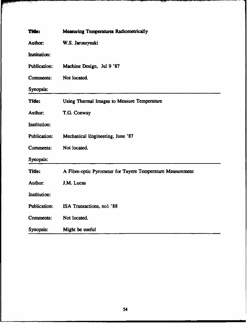
Tlhe: Measuring Temperatures Radiometricaily
Author W.S. Jaroszynski
Institution:
Publication: Machine Design, Jul 9 '87
Comments: Not located.
Synopsis:
Tide: Using Thermal Images to Measure Temperature
Author: T.G. Conway
Institution:
Publication: Mechanical Engineering, June '87
Comments: Not located.
Synopsis:
Tide: A Fibre-optic Pyrometer for Tuyere Temperature Measurement
Author: J.M. Lucas
Institution:
Publication: ISA Transactions, nol '88
Comments: Not located.
Synopsis: Might be useful
54
Tide: Radiation Thermometry; Easy and Accurate Without Touching
Author. G.R. Peacock
Institution:
Publication: ASTM Standard News, May '88
Comments: Not located.
Synopsis:
Title: Physics of Free-electron-laser Applications in the Visible and Infrared
Author:
Institution:
Publication: Journal of the Optical Society of America B, May '89
Comments: Not located.
Synopsis:
Title: Slag Deposition Monitor for Boiler Performance Enhancement
Author: F.E. LaVert et al.
Institution:
Publication: ISA Transactions
Comments: Not located.
Synopsis:
55

Title: Preliction of Three-dimensional Flows in Utility Boiler Furnaes and
Compnsonwith Experiments
Author. K. Gronr and W. Zinsw
Institution:
Publication: Combustion Science and Technology, Vol 58 nol-3 p43 '88
Comments: Too theoretical
Synopsis:
Title: European Companies Show New IR Detectors and Systems
Author. B. Dance
Institution:
Publication: Laser Focus Sept '88
Comments: Very general
Synopsis: Mentions products displayed at the Infrared Technology and ApplicationsExhibition held in London, U.K., June 1988. All are European companies.No specific applications are discussed.
Title: Versatile Detectors Meet IR Imaging Needs
Author: A.R. Tebo
Institution:
Publication: Laser Focus Nov '88
Comments: Not relevant
Synopsis: Discusses detectors for space observation and astronomical applications.
56

TIle: Infrared Scanning: Broad Range of Powerplant Uses
Author. E. Feit
Institution:
Publication: Electrical World Nov '88
Comments: Not located.
Synopsis:
Title: Keeping a Close Tab on the Heat
Author: G.J. McManus
Institution:
Publication: Iron Age Mar' 89
Comments: Not located.
Synopsis:
Tide: 1989 Trends in Detectors
Author: E.L. Dereniak
Institution:
Publication: Laser Focus World Jan '89
Comments: Not located.
Synopsis:
57

lift Mawrials Work Supports Desector Advances
Author:. A.R. Tebo
Institution:
Publication: Laser Focus World Jan '89
Comments: Not located.
Synopsis:
Title: Design and Simulated Performance of a CARS Spectrometer for DynamicTemperature Measurements Using Electronic Heterodyning
Author. MJ. Dean and ED. Thompson
Institution:
Publication: Applied Optics Apr '89
Comments: Not located.
Synopsis:
Tide: Optical Spectral RadiometricLAs Reflectance Method for Noninvasive
Measurement of Weld Pool Surface Temperature
Author. H.G. Kraus
Institution: Idaho National Engineering Laboratory
Publication: Optical Engineering December 1987
Comments: The problems encountered in measuring weld pool temperatures are notvery similar to those in furnace temperature measurement.
Synopsis: Describes a complicated experimental procedure for measuring surfacetemperature of a weld pool of a gas tungsten arc welding 1.5 mm thickstainless steel 304 plates using argon gas cover.
58

Title: Infrared Sensors Seek Out Hot Spots
Author.
Institution:
Publication: Electrical Construction and Maintenance
Comments: Not Relevant
Synopsis: Discusses the use of IR temperature sensors to locate trouble spots (suchas loose connections) in computers.
Title: Combustion of Solid Fuels
Author. B.A. Landry
Institution:
Publication: Encyclopedia of Chemical Technology, 1951
Comments: A good primer for learning the basic aspects of coal combustion.
Synopsis: Covers most types of coal burning technologies. Discusses burningcharacteristics of solid fuels in different air-feed regimes - overfeed,underfeed, and cross-feed. Discusses variations of coal bed surfacetemperatures with bed thickness and composition of combustion products."Little knowledge exists of the burning rates obtained in suspension fromspreader stokers".
Title: Combustion of Solid Fuels in Thin Beds
Author. E.P. Carman et al.
Institution: U.S. Bureau of Mines
Publication: Bulletin 503, Bureau of Mines, 1957
Comments:
Synopsis: Investigates effects of various fuel properties on ignition and combustioncharacteristics in a small pilot scale furnace.
59

APPENDIX B: Equipmeut Manufacturers Survey
61

Cceay: Weyerhauser Co.Sensor and Simulation Products DivisionTacoma, WA 98477
Phone: 206-924-6698
Contact: Gary Carlberg
Synopsis: Weyerhauser has developed a detection and imaging system thatappears to be totally applicable to our situation. They have botha visible-band and an infrared-band cameras. The camera ismounted in an air-cooled lens tube 3 to 4 feet long. The field ofview is normally set between 60 and 90 degrees, but can be larger.They can filter out smoke and flame, and electronically removemoving particles from the image. Images can be displayed in blackand white or color. The temperature image and processing system(TIPS) provides a movable window on the screen. By moving thewindow around, temperatures at different locations can beobtained. Images can be stored automatically or manually. Costsare $15,000 for the basic black and white camera, $20,000 for thecolor camera, $50,000 for the color camera complete with TIPS.
Mr. Carlberg is sending some descriptive literature and the nameof their nearest sale representative.
COcNny: SYN-FAB7863 Schillinger Park RoadMobile, AL 36608
Phone: 205-633-4942
Contact: Diann Ragazzo/Mark Kennedy
Synopsis: SYN-FAB manufacturers a high definition closed circuit TVmonitoring system called BoilervisionT" that is used to measuretemperatures inside boilers, including burning-bed temperatures.Boilervision detects radiation in the visible and near infraredregions (500 to 1100 nanometers). They also have a patentedinfrared monitor. They also have an image analyzer that can beused in conjunction with the radiation detectors to display atemperature image on a video terminal. The temperature at anypoint is displayed when a moveable crosshair is positioned at thatpoint on the screen. Vertical or horizontal temperaturedistributions can also be displayed graphically. The standardfield of view is 90 degrees. Costs are $12,500 for the basecamera and $5,000 for the image analyzer.
Mr. Kennedy claims their system will provide the capabilities wedesire. SYN-FAB has monitoring systems installed in manyinstallations, including coal-fired industrial and utilityboilers. They are able to use the visible spectrum system in most(90%) cases, switching to their IR system for Osmokey*applications (such as high-moisture fuels like municipal waste).They have sent us more descriptive literature and a video tape offour actual operations, and also will suggest some actualinstallations where we may see their equipment in operation.
62

C sEGM2 ughes Aircraft Co. Industrial Products Div.655-T 11 Camino RealCarlsbad, CA 92009
Phone: 619-931-3000
Contact: Tom Black, area representative, Sparks, MD, 301-472-2416
Synopsis: Hughes has a number of systems that should meet our requirements.Prices range from $11,000 to $50,000. Filters are used topenetrate flames and smoke. He has sent some descriptiveliterature and a "professional* video tape of numerousinstallations. After we review his material, we will contact himagain.
Ccamoay Inframetrics12 Oak ParkBedford, MA 01730
Phone: 508-670-5555
Contact: Tom Scanlon
Synopsis: Their equipment detects temperature differences on Ojust about anysurface8. Gases between the burning bed surface and the detectordon't pose much of a problem. Particulates could be a problem.If the particulates are uniformly distributed and are cooler thanthe target, it should be possible to get a good feel for howevenly the bed is burning.
George Baird, 302-658-7590, is Inframetrics' representative in ourarea. He can demonstrate the equipment.
Cmaenys Westinghouse Combustion Control DivisionP.O. Drawer 901Orrville, OH 44667
Phone: 800-628-1200
Contact: Blane Shank
Synopsis: The temperature range we are interested in is beyond the scope oftheir instrument. For infrared detection to work, the detectormust be fairly close to the object of interest. Temperature maynot be the right variable to measure (to determine fuel-ash bedthickness).
Ctemy:s IRCON, Inc.7301-T N. Caldwell Ave.Niles, IL 60648
Phone: 312-967-5151
Contact: Mr. Hassell
Synopsis: They sell spot radiometers, but no imagers. Prices for portableunits start at $2300. A datalogger accessory can store up to 1000readings. A demonstration can be arranged with a local salesrepresentative. Mr. Hassell was of the opinion that "If you can'tsee the flame with your eye, then the pyrometer can't see iteither.', which seems contradictory with all the otherinformation.
63

COewMO Z3 Technology Corp.4475-T Dupont Court, No. 9Ventura, CA 93003
Phone: 805-644-9544
Contact: Brian Smatko
Synopsis: They don't have any equipment applicable to the temperature rangeof our interest. Mr. Smatko suggested that SYN-FAB's loiervisionmight be suitable.
COmpemS Infrared Associates Inc.1000 Rte 130 E. ParkCrabbury, NJ 08512
Phone: 609-395-7600
Contact:
Synopsis: They manufacture only components, and do not retail completeassemblies.
Compaws Electro-Optical Systems271-A Grear Valley PkwyMalvern, PA 19355
Phone: 215-644-4672
Contact:
Synopsis: They do not manufacture anything for our application. Suggestedcontacting Omega Engineering.
Company Land Instruments Inc.2525 Pearl Buck Rd.Bristol, PA 19007
Phone: 215-781-0700
Contact: Rich Gagg
Synopsis: They manufacturer spot radiometers. These are not normally usedin a "scanning" mode. A thermal imager is what we need for ourapplication. He recovimended a system manufactured by HughesAircraft, and suggested contacting Tom Black, the arearepresentative for Hughes Aircraft.
64

cemews B & W Applied Measurement TchnologiesContract Research Division1562 Deeson St.Alliance, OH 44601
Phone: 216-829-7617
Contact: Jeff Koksal
Synopsis: The Flame Quality Analyzer (FQA) was originally developed to lookat coal flames. The FQA will pick up the hottest temperature inits line of sight. Our application is similar to their "burneraapplication. The FQA is a two-color pyrometer, which eliminateserrors that can occur in a single color radiometer if there arevariations in emissivity.
The FQA is not a commercial product because the market does notcurrently exist in the utility industry. (The FQA can detectareas of uneven air flow distribution, but since there is nomethod for redistributing the flow in today's boilers, it is of nopractical value.) They could sell us expertise and a prototypesystem.
Compny: AGEDA Infrared Systems550 County Ave.Secaucus, NJ 07094
Phone: 201-867-5390
Contact: Harry Devlin, area representative, Sparks, MD, 301-771-4506
Synopsis: He recommended a portable scanner with a flame filter. He issending some literature on the AGMA line. They can recordscanned images on videotape, then get prints of any frame thatincludes a temperature readout and a date-time stamp. Pricesrange from $30,000 to $50,000. An imager would probably be betterfor our application.
Comany& Omega Engineering Inc.One Omega DriveStamford, CT 06907
Phone: 800-826-6342
Contact:
Synopsis: They do not sell imagers. They have infrared pyrometers that cansee through blue flames, but not yellow flames. Their leastexpensive hand-held pyrometer costs $700 to $800. Pyrometers areshown in section C-1 in their catalog.
Comanys Infrared Industries Inc.12151-T Research ParkwayOrlando, FL 32826
Phone: 407-282-7700
Contact:
Synopsis: They manufacture only components, and do not retail completeassemblies.
65

CCEays Nanmac Corp.7 Mayhew StreetFramingham, MA 01701
Phone: 508-872-4811
Contact:
Synopsis: They do not have remote sensing equipment. They concentrate oncontact measurement. Suggested contacting Infraspection Institutein Shelburn, VT as a source of pertinent manufacturers.
CcOWWys Infraspection Institute
Shelburn, VT
Phone: 802-985-2500
Contact: Paul Grover
Synopsis: Recomuended contacting Sensor and Simulation Products Division ofWeyerhauser Co. as having sexactly what we want4. InfraspectionInstitute conducts training sessions on equipment and how to useit. He has sent some literature on their activities.
Caompws Infrared Services Inc.P.O. Box 485-TMontville, NJ 07045
Phone: 201-263-1177
Contact: Phil Lasker
Synopsis: Waiting for a return cail.
66

USACERL DISTRIBUTION
Chief of Engiaes Fort McCoy 54656 Tyndall AFB 32403ATTN: CEHEC-IM-LH (2) ATTN: AFZR-DE ATTN: AFESC Program O(cATTN: CEHEC-IM-LP (2) Fort Stewart 31314 ATTN: Engr & Srvc LabATTN: CERD-L ATTN: AFZP-DEF
Ft Buchanan 00934 Amencan Public Workn Assoc. 60637CECPW ATTN: Envr Office
ATTN: CECPW-FU-P 22060 Ft Devens 01433 US Army Envr Hygiene AgencyATTN: AFZD-DE ATTN: HSHB-ME 21010
US Army Engr District Fort Drum 13602ATTN: Library (40) ATTN: AFZS-EH-E US Gov't Printing Office 20401
Fort Irwin 92310 ATFN: Rac SecDeposit Sac (2)US Army Engr Division ATTN: AFZJ-EH
ATTN: Library (13) Fort Hood 76544 Nat'l Institue of Standards & TechA'ITN: AFZF-DE-AES Engr AITN: Library 20899
US Army Europe Fort Meade 20755ATTN: AEAEN-ODCS 09014 ATTN: AFKA-ZI-EH-A Defense Tech Info Can 22304
ATTN: DTIC-FAB (2)US Army Materiel Command (AMC) National Guard Bureau 20310Redstone Arsenal 35809 ATITN: Installations Div AMC-Dir, Inst, & Svca
ATTN: DESMI-KLF ATTN: DEH (23)Jefferson Proving Ground 47250 TRADOC
ATTN: STEJP-LD-F/DEH ATTN: DEH (13) NAVPACLasterkenny Army Depot Fort Monroe 23651 ATTN: Code 1652B 22332-2300
ATTN: SDSLE-ENN 17201 ATTN: ATBO-GPueblo Army Depot 81008 Carlisle Barracs 17013 NEESA
AMN: SDSTE-PUI-F ATTN: ATZE-DIS ATIN: Code IIIC2Dugway Prvmi Ground 84022 Fort Eustis 23604 Port Hueneme CA 93043-5014
ATTN: STEDP-EN ATTN: DEHTooele Army Depot 84074 Fort Chaffee 72905 US Army Petroleum Center
ATTN: SDSTE-ELF ATTN: ATZR-ZF ATTN: STRGP-TFYuma Proving Ground 85365 Fort Sill 73503 New Cumberland PA 17070-5008
ATTN: STEYP-EH-E ATTN: ATZR-ETobyhanna Army Depot 18466 HQ Defense Supply Agency
ATTN: SDSTO-EH USARPAC 96858 ATTN: DSAH-PRQSeneca Army Depot 14541 ATTIN: DEH Cameron Station
ATTN: SDSSE-HE ATIN: APEN-A Alexandria VA 22314-4105Aberdeen Proving Ground
ATTN: STEAP-DEH 21005 CEWES 39180 150Sharpe Army Depot 95331 ATTN: Library 09s93
ATTN: SDSSH-EFort Monmouth 07703 CECRL 03755
ATTN: SELFM-EH-E ATIN: LibrarySavanna Army Depot 61074
AMTN: SDSLE-VAE USA AMCCOMRock Island Arsenal ATTIN: Facilities Engr 21719
ATTN: SMCRI-EH ATTN: AMSMC-IR 61299ATTN: SMCRI-TL ATFN: Facilities Engr (3) 85613
Watervliet Arsenal 12189ATTN: SMCWV-EH Defense Logistics Agency
Red River Army Depot 76102 ATTN: DLA-WI 22304ATTN: SDSRR-G
Hary Diamond Lab Walter Reed Army Medical Ctr 20307ATTN: Library 20783
White Sands Missile Range 88002 Naval Facilities Engr CommandATTN: Library ATTN: Naval Civil Engr Laboratory (3)
Corpus Christi Army Depot 93043ATIN: SDSCC-ECD 78419
US Army HSCFORSCOM Fort Sam Houston 78234ATTN: Facilities Engr (12) ATTN: HSLO-FFort Bragg 28307 Fitzsimons Army Medical Ctr
ATTN: AFZA-DE ATTN: HSHG-DEH 80045Fort Campbell 42223
ATTN: AFZB-DEH
This publication was reproduced on recycled paper. U uS. GOVERNMENT PRINTING OFFICE: 1993-4510140014