Embed Size (px)
Citation preview
POLLACK PERIODICA An International Journal for Engineering and Information Sciences
DOI: 10.1556/606.2016.11.2.6 Vol. 11, No. 2, pp. 65–74 (2016)
www.akademiai.com
HU ISSN 1788–1994 © 2016 Akadémiai Kiadó, Budapest
INVESTIGATION OF INTERNAL FORCES IN THE RAIL DUE TO THE INTERACTION OF CWR
TRACKS AND STEEL RAILWAY BRIDGES WITH BALLASTED TRACK SUPERSTRUCTURE
1 Helga PAPP, 2 Nándor LIEGNER
1,2 Department of Highway and Railway Engineering, Faculty of Civil Engineering, Budapest University of Technology and Economics, H-1521 Budapest, P.O.B. 91, Hungary,
e-mail: [email protected], [email protected]
Received 11 November 2015; accepted 21 March 2016
Abstract: The technical specifications of D.12/H of Hungarian State Railways specifies that a continuously welded rail track can be constructed through a bridge without being interrupted if the expansion length of the bridge is no longer than 40 m. If the expansion length is greater than 40 m, rail expansion joints have to be constructed. The aim of the research is to create finite-element models with which the interaction of continuously welded rail track and steel railway bridges can be calculated and to provide technical solutions of track structures on bridges with ballasted track so rail expansion joints can be omitted. Keywords: Steel railway bridge, Expansion joints, Ballasted track, Rail restraint, Longitudinal stiffness
1. Introduction
In the paper a finite-element model has been developed to determine the axial forces in the rail, bridge structure and the bearing in case of a two-span-bridge with an expansion length of 40 m resulting from the change of temperature, braking or acceleration of trains. Following this, the model has been converted into bridges with 70 m and 100 m expansion lengths with the purpose to find technical solutions, with their application the resultant normal forces do not exceed - or exceed to a less extent - those values resulting in bridges with expansion length of 40 m. By the application of these solutions, the Continuously Welded Rail (CWR) track can be constructed through

66 H. PAPP, N. LIEGNER
Pollack Periodica 11, 2016, 2
the bridge without interruption. Only the joining of CWR tracks from earthworks to steel railway bridges with ballasted track superstructure are discussed in this paper.
2. Laboratory testing of rail fastenings
Test series have been carried out in the Laboratory of the Department of Highway and Railway Engineering, Budapest University of Technology and Economics, in order to determine the longitudinal stiffness and the longitudinal rail restraint of different rail fastenings to model the interaction of the rail and bridges precisely. The tests were carried out according to standard EN 13146-1:2012 [1]. The test arrangement is shown in Fig. 1. The concrete sleeper, the rail and the fastening assembly were fixed to a horizontal base. A tensile load at a constant rate of 10 kN/min was applied to one end of the rail, while the load and the displacement were measured. When the rail slipped in the fastening, the load was reduced to zero rapidly and the rail displacement was measured for two minutes. Without removing or adjusting the fastening, the cycle was repeated further three times with three minute intervals in the unloaded condition between each cycle. The rail displacement was measured with inductive transducer of type Hottinger Baldwin Messtechnik (HBM) WA20 mm, and the load was measured with force transducer of type HBM C9B 50 kN. The data acquisition unit and measuring amplifier was HBM Quantum MX 840, evaluation software was Catman AP. The sampling rate of frequency was 10 Hz.
Fig. 1. Longitudinal rail restraint test (KS fastening)
The maximum load to produce an initial elastic displacement was determined in each cycle. The value of the first cycle was discarded. The average of the second, third and fourth cycle was calculated and considered to be the longitudinal rail restraint. The fastening assembly is unable to take on higher forces, the rail will slip in the fastening longitudinally.
INTERACTION OF CWR TRACKS AND STEEL RAILWAY BRIDGES 67
Pollack Periodica 11, 2016, 2
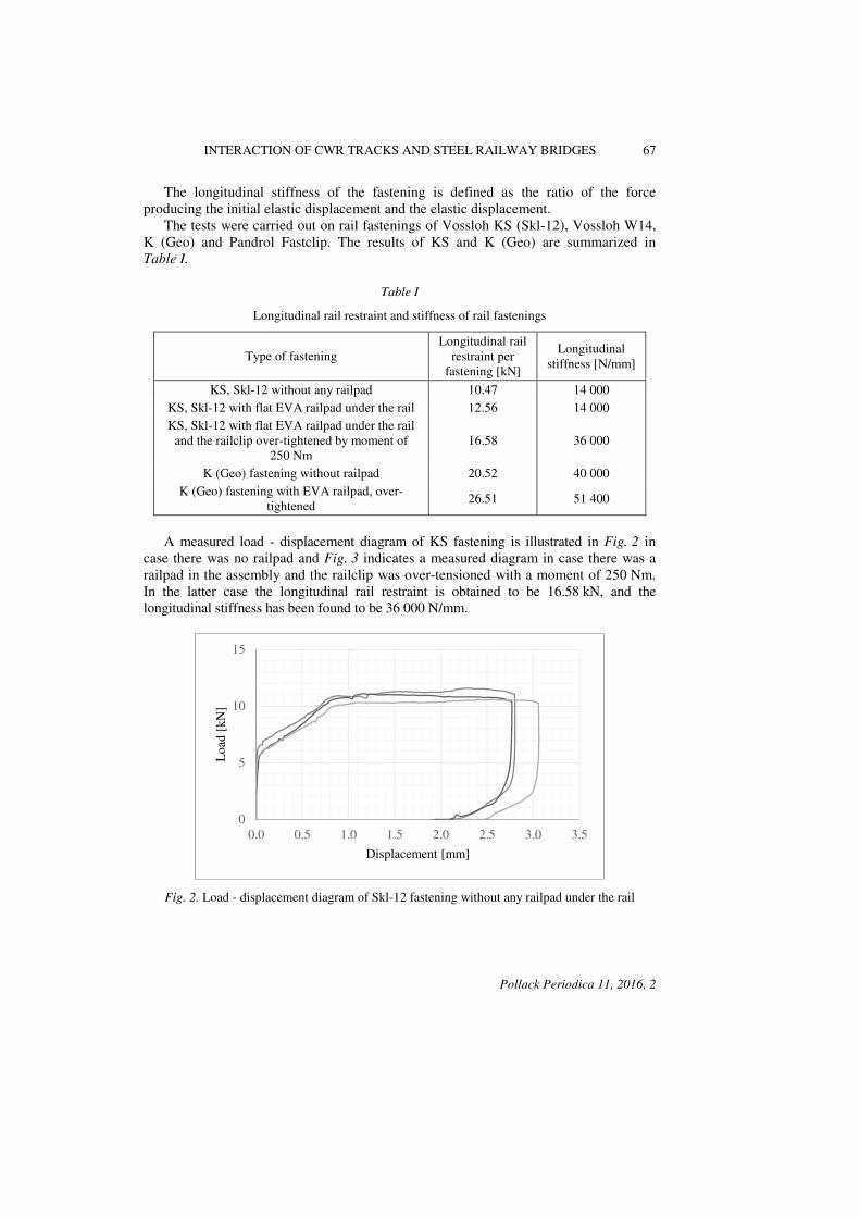
The longitudinal stiffness of the fastening is defined as the ratio of the force producing the initial elastic displacement and the elastic displacement. The tests were carried out on rail fastenings of Vossloh KS (Skl-12), Vossloh W14, K (Geo) and Pandrol Fastclip. The results of KS and K (Geo) are summarized in
Table I.
Table I
Longitudinal rail restraint and stiffness of rail fastenings
Type of fastening Longitudinal rail
restraint per fastening [kN]
Longitudinal stiffness [N/mm]
KS, Skl-12 without any railpad 10.47 14 000 KS, Skl-12 with flat EVA railpad under the rail 12.56 14 000 KS, Skl-12 with flat EVA railpad under the rail
and the railclip over-tightened by moment of 250 Nm
16.58 36 000
K (Geo) fastening without railpad 20.52 40 000 K (Geo) fastening with EVA railpad, over-
tightened 26.51 51 400
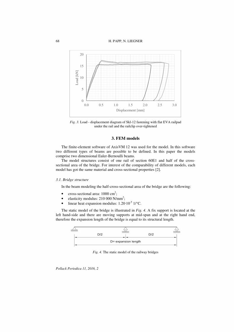
A measured load - displacement diagram of KS fastening is illustrated in Fig. 2 in case there was no railpad and Fig. 3 indicates a measured diagram in case there was a railpad in the assembly and the railclip was over-tensioned with a moment of 250 Nm. In the latter case the longitudinal rail restraint is obtained to be 16.58 kN, and the longitudinal stiffness has been found to be 36 000 N/mm.
Fig. 2. Load - displacement diagram of Skl-12 fastening without any railpad under the rail
0
5
10
15
0.0 0.5 1.0 1.5 2.0 2.5 3.0 3.5
Loa
d [k
N]
Displacement [mm]
68 H. PAPP, N. LIEGNER
Pollack Periodica 11, 2016, 2
Fig. 3. Load - displacement diagram of Skl-12 fastening with flat EVA railpad under the rail and the railclip over-tightened
3. FEM models
The finite-element software of AxisVM 12 was used for the model. In this software two different types of beams are possible to be defined. In this paper the models comprise two dimensional Euler-Bernoulli beams. The model structures consist of one rail of section 60E1 and half of the cross-sectional area of the bridge. For interest of the comparability of different models, each model has got the same material and cross-sectional properties [2].
3.1. Bridge structure
In the beam modeling the half-cross-sectional area of the bridge are the following:
• cross-sectional area: 1000 cm2; • elasticity modulus: 210 000 N/mm2; • linear heat expansion modulus: 1.20·10-5 1/°C.
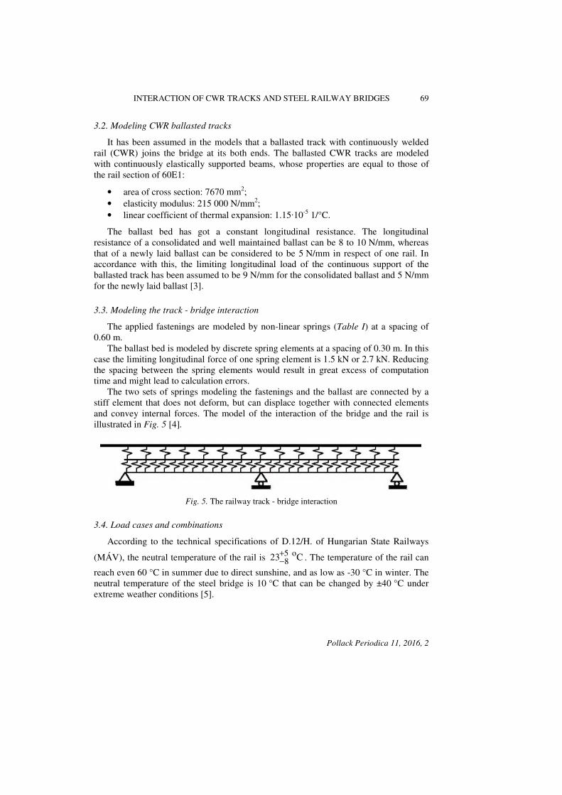
The static model of the bridge is illustrated in Fig. 4. A fix support is located at the left hand-side and there are moving supports at mid-span and at the right hand end, therefore the expansion length of the bridge is equal to its structural length.
Fig. 4. The static model of the railway bridges
0
5
10
15
20
0.0 0.5 1.0 1.5 2.0 2.5 3.0
Loa
d [k
N]
Displacement [mm]
INTERACTION OF CWR TRACKS AND STEEL RAILWAY BRIDGES 69
Pollack Periodica 11, 2016, 2
3.2. Modeling CWR ballasted tracks
It has been assumed in the models that a ballasted track with continuously welded rail (CWR) joins the bridge at its both ends. The ballasted CWR tracks are modeled with continuously elastically supported beams, whose properties are equal to those of the rail section of 60E1:
• area of cross section: 7670 mm2; • elasticity modulus: 215 000 N/mm2; • linear coefficient of thermal expansion: 1.15·10-5 1/°C.
The ballast bed has got a constant longitudinal resistance. The longitudinal resistance of a consolidated and well maintained ballast can be 8 to 10 N/mm, whereas that of a newly laid ballast can be considered to be 5 N/mm in respect of one rail. In accordance with this, the limiting longitudinal load of the continuous support of the ballasted track has been assumed to be 9 N/mm for the consolidated ballast and 5 N/mm for the newly laid ballast [3].
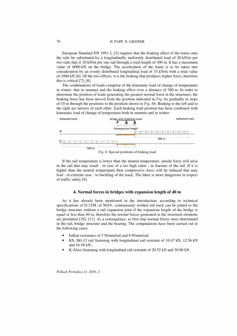
3.3. Modeling the track - bridge interaction
The applied fastenings are modeled by non-linear springs (Table I) at a spacing of 0.60 m. The ballast bed is modeled by discrete spring elements at a spacing of 0.30 m. In this case the limiting longitudinal force of one spring element is 1.5 kN or 2.7 kN. Reducing the spacing between the spring elements would result in great excess of computation time and might lead to calculation errors. The two sets of springs modeling the fastenings and the ballast are connected by a stiff element that does not deform, but can displace together with connected elements and convey internal forces. The model of the interaction of the bridge and the rail is illustrated in Fig. 5 [4].
Fig. 5. The railway track - bridge interaction
3.4. Load cases and combinations
According to the technical specifications of D.12/H. of Hungarian State Railways
(MÁV), the neutral temperature of the rail is C 23 o58
+
−. The temperature of the rail can
reach even 60 °C in summer due to direct sunshine, and as low as -30 °C in winter. The neutral temperature of the steel bridge is 10 °C that can be changed by ±40 °C under extreme weather conditions [5].
70 H. PAPP, N. LIEGNER
Pollack Periodica 11, 2016, 2
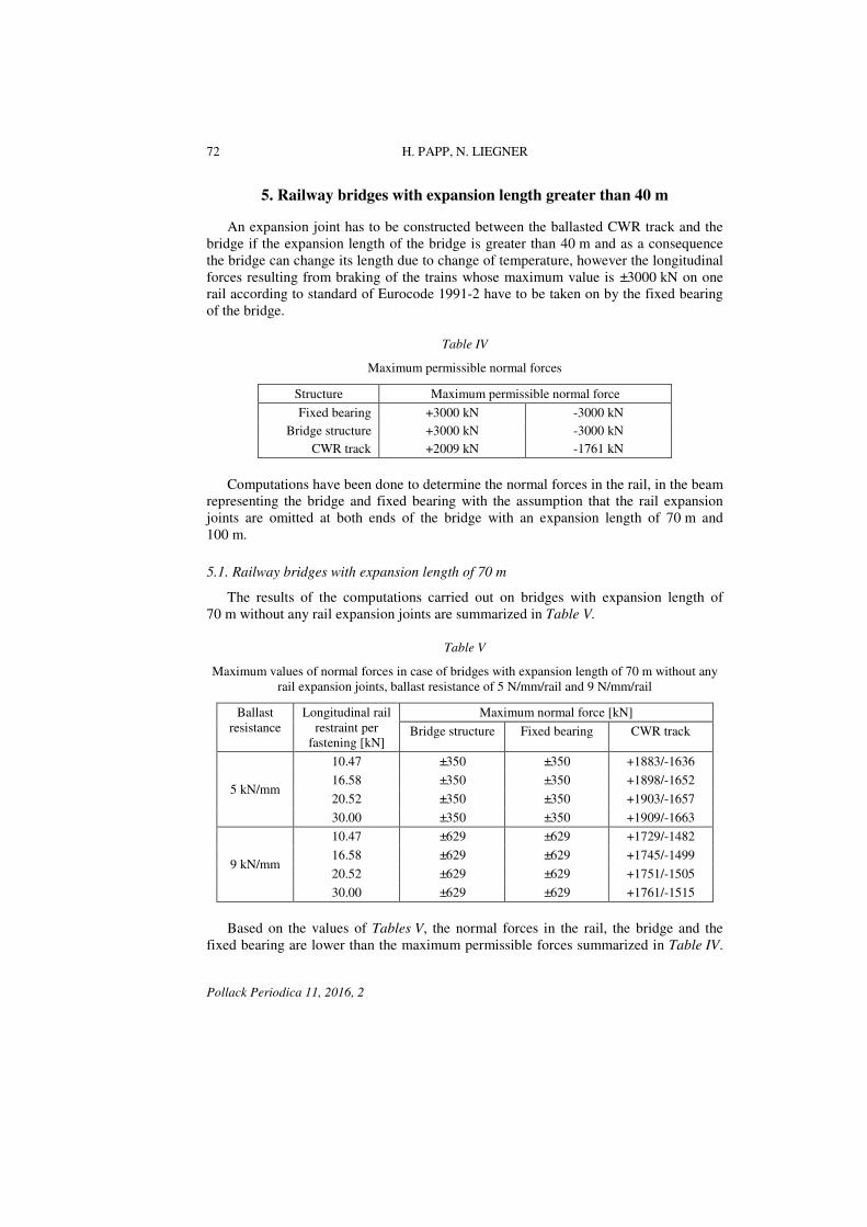
European Standard EN 1991-2, [3] requires that the braking effect of the trains onto the rails be substituted by a longitudinally uniformly distributed load of 20 kN/m per two rails that is 10 kN/m per one rail through a total length of 300 m. It has a maximum value of 6000 kN on the bridge. The acceleration of the trains is to be taken into consideration by an evenly distributed longitudinal load of 33 kN/m with a total value of 1000 kN [6]. Of the two effects, it is the braking that produces higher force, therefore this is critical [7], [8]. The combinations of loads comprise of the kinematic load of change of temperature in winter, that in summer and the braking effect over a distance of 300 m. In order to determine the position of loads generating the greatest normal force in the structures, the braking force has been moved from the position indicated in Fig. 6a gradually in steps of 10 m through the positions to the position shown in Fig. 6b. Braking to the left and to the right are mirrors of each other. Each braking load position has been combined with kinematic load of change of temperature both in summer and in winter.
Fig. 6. Special positions of braking load
If the rail temperature is lower than the neutral temperature, tensile force will arise in the rail that may result - in case of a too high value - in fracture of the rail. If it is higher than the neutral temperature then compressive force will be induced that may lead - in extreme case - to buckling of the track. The latter is more dangerous in respect of traffic safety [9].
4. Normal forces in bridges with expansion length of 40 m
As it has already been mentioned in the introduction, according to technical specifications of D.12/H. of MÁV, continuously welded rail track can be joined to the bridge structure without a rail expansion joint if the expansion length of the bridge is equal or less than 40 m, therefore the normal forces generated in the structural elements are permitted [10], [11]. As a consequence, as first step normal forces were determined in the rail, bridge structure and the bearing. The computations have been carried out in the following cases:
• ballast resistance of 5 N/mm/rail and 9 N/mm/rail; • KS, Skl-12 rail fastening with longitudinal rail restraint of 10.47 kN, 12.56 kN
and 16.58 kN; • K (Geo) fastening with longitudinal rail restraint of 20.52 kN and 30.00 kN.

INTERACTION OF CWR TRACKS AND STEEL RAILWAY BRIDGES 71
Pollack Periodica 11, 2016, 2
As the distance between the rail fastenings is 0.6 m in the model, the 30.0 kN longitudinal rail restraint of a discrete fastening will result in a specific rail resistance of 30 kN/0.6 m = 50 kN/m. The longitudinal stiffness of the fastenings is summarized in Table I. Table II summarizes the results obtained in case of a ballast resistance of 5 N/mm/rail, and Table III indicates those with 9 N/mm/rail of ballast resistance.
Table II
Maximum normal forces in case of bridge with ballasted track and expansion length of 40 m, ballast resistance of 5 N/mm
Longitudinal rail restraint per
fastening [kN]
Maximum normal force [kN]
Bridge structure Fixed bearing CWR track
10.47 ±200 ±200 +1861/-1614 12.56 ±200 ±200 +1862/-1616 16.58 ±200 ±200 +1867/-1621 20.52 ±200 ±200 +1871/-1624 30.00 ±200 ±200 +1879/-1632
Table III
Maximum normal forces in case of bridge with ballasted track and expansion length of 40 m, ballast resistance of 9 N/mm
Longitudinal rail restraint per
fastening [kN]
Maximum normal force [kN]
Bridge structure Fixed bearing CWR track
10.47 ±359 ±359 +1557/-1311 12.56 ±359 ±359 +1560/-1314 16.58 ±359 ±359 +1568/-1322 20.52 ±359 ±359 +1572/-1325 30.00 ±359 ±359 +1578/-1331
It can be concluded form Table II and Table III that with increasing ballast resistance the internal normal forces will be higher in the beam representing the bridge and in the bearing and will be lower in the rail. It has also been obtained that the lower the rail restraint is the lower the normal forces are in the rail. Normal internal forces were also determined in case the railway track superstructure is constructed with wooden sleepers and the sleepers are directly fixed to the bridge structure without any ballast bed. The normal internal forces in this case have been obtained to be remarkably higher than in case of a ballasted superstructure. Taking these values into consideration and the maximum limit values of 3000 kN of braking force per one rail, Table IV summarizes the maximum permissible normal forces [12].
72 H. PAPP, N. LIEGNER
Pollack Periodica 11, 2016, 2
5. Railway bridges with expansion length greater than 40 m
An expansion joint has to be constructed between the ballasted CWR track and the bridge if the expansion length of the bridge is greater than 40 m and as a consequence the bridge can change its length due to change of temperature, however the longitudinal forces resulting from braking of the trains whose maximum value is ±3000 kN on one rail according to standard of Eurocode 1991-2 have to be taken on by the fixed bearing of the bridge.
Table IV
Maximum permissible normal forces
Structure Maximum permissible normal force
Fixed bearing +3000 kN -3000 kN Bridge structure +3000 kN -3000 kN
CWR track +2009 kN -1761 kN
Computations have been done to determine the normal forces in the rail, in the beam representing the bridge and fixed bearing with the assumption that the rail expansion joints are omitted at both ends of the bridge with an expansion length of 70 m and 100 m.
5.1. Railway bridges with expansion length of 70 m
The results of the computations carried out on bridges with expansion length of 70 m without any rail expansion joints are summarized in Table V.
Table V
Maximum values of normal forces in case of bridges with expansion length of 70 m without any rail expansion joints, ballast resistance of 5 N/mm/rail and 9 N/mm/rail
Ballast resistance
Longitudinal rail restraint per
fastening [kN]
Maximum normal force [kN]
Bridge structure Fixed bearing CWR track
5 kN/mm
10.47 ±350 ±350 +1883/-1636
16.58 ±350 ±350 +1898/-1652
20.52 ±350 ±350 +1903/-1657
30.00 ±350 ±350 +1909/-1663
9 kN/mm
10.47 ±629 ±629 +1729/-1482
16.58 ±629 ±629 +1745/-1499
20.52 ±629 ±629 +1751/-1505
30.00 ±629 ±629 +1761/-1515
Based on the values of Tables V, the normal forces in the rail, the bridge and the fixed bearing are lower than the maximum permissible forces summarized in Table IV.
INTERACTION OF CWR TRACKS AND STEEL RAILWAY BRIDGES 73
Pollack Periodica 11, 2016, 2
Increasing the expansion length from 40 m to 70 m will result in an excess force in the rail of 1.5% in case of 5 N/mm of ballast resistance and 13% in case of 9 N/mm ballast resistance. The longitudinal rail restraint hardly influences the normal forces. Continuously welded rail track can be constructed through bridges with ballasted track and an expansion length of 70 m without rail expansion joints even if the rail fastening has got a longitudinal rail restraint of 30 kN that will result in a specific rail resistance of 30 kN/0.6 m = 50 kN/m. The normal forces in this case will be less than those in Table IV. In case of an expansion length of 70 m, the rail expansion joints can be omitted.
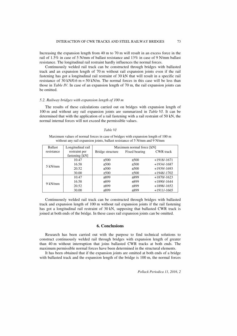
5.2. Railway bridges with expansion length of 100 m
The results of these calculations carried out on bridges with expansion length of 100 m and without any rail expansion joints are summarized in Table VI. It can be determined that with the application of a rail fastening with a rail restraint of 50 kN, the normal internal forces will not exceed the permissible values.
Table VI
Maximum values of normal forces in case of bridges with expansion length of 100 m without any rail expansion joints, ballast resistance of 5 N/mm and 9 N/mm
Ballast resistance
Longitudinal rail restraint per
fastening [kN]
Maximum normal force [kN] Bridge structure Fixed bearing CWR track
5 kN/mm
10.47 ±500 ±500 +1918/-1671 16.58 ±500 ±500 +1934/-1687 20.52 ±500 ±500 +1939/-1693 30.00 ±500 ±500 +1948/-1702
9 kN/mm
10.47 ±899 ±899 +1870/-1623 16.58 ±899 ±899 +1890/-1644 20.52 ±899 ±899 +1898/-1652 30.00 ±899 ±899 +1911/-1665
Continuously welded rail track can be constructed through bridges with ballasted track and expansion length of 100 m without rail expansion joints if the rail fastening has got a longitudinal rail restraint of 30 kN, supposing that ballasted CWR track is joined at both ends of the bridge. In these cases rail expansion joints can be omitted.
6. Conclusions
Research has been carried out with the purpose to find technical solutions to construct continuously welded rail through bridges with expansion length of greater than 40 m without interruption that joins ballasted CWR tracks at both ends. The maximum permissible normal forces have been determined in the structural elements. It has been obtained that if the expansion joints are omitted at both ends of a bridge with ballasted track and the expansion length of the bridge is 100 m, the normal forces

74 H. PAPP, N. LIEGNER
Pollack Periodica 11, 2016, 2
in the modeled structural elements will not exceed those force generated in a bridge with an expansion length of 40 m and with wooden sleepers directly fastened to it. It can be concluded that a ballasted track is more advantageous in respect of track-bridge longitudinal interaction than a bridge with wooden sleepers directly fastened to it. Based on the developed calculations the rail expansion joints can be omitted and the CWR track can be constructed through a bridge without being interrupted up to an expansion length of 100 m in case of ballasted bridges. Lower internal forces will be generated from longitudinal loads than in case of a bridge with wooden sleepers with an expansion length of 40 m.
Acknowledgements
This work has been undertaken as a part of the 11th Miklós Iványi International PhD & DLA Symposium held at the Faculty of Engineering and Information Technology, University of Pécs.
References
[1] EN 13146-1:2012, European Standard, Railway applications, track, test methods for fastening systems, Part 1, Determination of longitudinal rail restraint, European Committee for Standardization, ICS 93.100, 2012.
[2] Major Z. Special problems of interaction between railway track and bridge, Pollack
Periodica, Vol. 8, No. 2, 2013, pp. 97–106. [3] Ruge P., Widarda D. R., Schmälzlin G., Bagayoko L. Longitudinal track-bridge interaction
due to sudden change of coupling interface, Computers & Structures, Vol. 87, No. 1-2, 2009, pp. 47–58.
[4] Birk C., Ruge P. Longitudinal track-structure interaction on railway bridges, Proceedings
in Applied Mathematics Mechanics, Vol. 6, No. 1, 2006, pp. 209–210. [5] MSZ-07-2306/2-90T, National Standard, Static design of railway bridges, forces acting on
bridges, (in Hungarian) 1990. [6] MSZ EN 1991-2:2006, European Standard, Eurocode 1, Actions on bridges, Part 2, Traffic
loads on bridges, European Committee for Standardization, ICS 91.010.30, 93.040, 2006. [7] Jiang J. Z. Additional longitudinal forces in continuously welded rails and their
transmission on railway bridges, China Railway Science, Vol. 19, No. 2, 1998, pp. 67–75. [8] Yang Y. B., Yau J. D., Wu Y. S. Vehicle-bridge interaction dynamics, With application to
high-speed railways, World Scientific Publishing Co. Pte. Ltd. 2004. [9] Fryba L. Thermal interaction of long welded rails with railway bridges, Rail International,
Vol. 16, No. 3, 1985, pp. 5–24. [10] MÁV Zrt. D12/H, Technical specifications, Construction and maintenance of continuously
welded rail tracks, (in Hungarian) Budapest, 2009. [11] MÁV D.54, Technical specification of track construction and maintenance, (in Hungarian)
Közdok, Budapest, 1986. [12] Liegner N., Kormos Gy., Papp H. Solutions of omitting rail expansion joints in case of steel
railway bridges with wooden sleepers, Periodica Polytechnica, Vol. 59, No. 4, 2015, pp. 495–502.