Embed Size (px)
Citation preview
Master’s DissertationEngineering
Acoustics
FANNY SANDBERG Report TV
BA-5049
FAN
NY
SAN
DBERG IN
VESTIG
ATIO
N O
F IMPA
CT SO
UN
D B
EHA
VIO
UR
IN LIG
HTW
EIGH
T FLOO
R C
ON
STRU
CTIO
NS
INVESTIGATION OF IMPACT SOUNDBEHAVIOUR IN LIGHTWEIGHT FLOORCONSTRUCTIONSA Market Survey and Finite Element Analysis
TVBA-5049HO.indd 1TVBA-5049HO.indd 1 2016-10-13 12:30:042016-10-13 12:30:04

DEPARTMENT OF CONSTRUCTION SCIENCES
DIVISION OF ENGINEERING ACOUSTICS
ISRN LUTVDG/TVBA--16/5049--SE (1-77) | ISSN 0281-8477
MASTER’S DISSERTATION
Supervisors: DELPHINE BARD, Assoc. Prof., Div. of Engineering Acoustics, LTH, Lundtogether with EMMA ARVIDSSON, MSc, and ERLING NILSSON, PhD, Saint-Gobain, Ecophon AB.
Examiner: Professor ERIK SERRANO, Div. of Structural Mechanics, LTH, Lund.
Copyright © 2016 by Division of Engineering Acoustics,Faculty of Engineering LTH, Lund University, Sweden.
Printed by Media-Tryck LU, Lund, Sweden, June 2016 (Pl).
For information, address:Division of Engineering Acoustics,
Faculty of Engineering LTH, Lund University, Box 118, SE-221 00 Lund, Sweden.
Homepage: www.akustik.lth.se
FANNY SANDBERG
INVESTIGATION OF IMPACT SOUNDBEHAVIOUR IN LIGHTWEIGHT FLOOR
CONSTRUCTIONSA Market Survey and Finite Element Analysis


A B S T R A C T
In the last years, the interest in high-rise timber framed building has gone up resulting inan increased demand for good solutions regarding sound insulation. Due to the worldwidegrowing interest in environmental issues, it has become of greater importance for companiesto find ways to take care of their residue, instead of throwing it away. This can benefit boththe environment, as less new material is used, and the economy, as less material goes to waste.Ecophon is presently developing a new type of lightweight aggregate (LWA) from glass woolresidue that comes from their production of sound absorbing tiles. It will be investigated ifthese new LWA’s can be used as ballast in intermediate floors.
The aim of this thesis is to find intermediate floor constructions where the new materials canbe used. A market survey will provide the basis and suggest a few specific floor constructionswhere the LWA’s could replace other insulation materials.
To further investigate the materials sound insulation properties in an actual floor, a FEM-calculation in Abaqus will be used. The FEM-modelling will be executed on a standard typefloor to ease further comparison with other filling materials. The FEM-modelling will givethe opportunity to compare the new materials with others that are commonly used in today’smarket. The results from the FEM-calculation will also be compared to measurements doneby the consulting company Akustikverkstan.
Analyzing accelerations in the bottom plate for frequencies up to 125 Hz showed no signif-icant improvement when adding LWA 1 into the floor. The accelerations decreased for somefrequencies but then again got worse for others. To motivate an improvement, the accelera-tions would have to be lowered for all calculated frequencies. The most likely reason for theLWA’s acoustic performance is its lack of stiffness which otherwise is the main reason to addmass. In this case, the mass is added without providing the necessary amount of stiffness.
With the measurements of the laboratory room at Akustikverkstan, it was possible to recal-culate the accelerations in the bottom plate of the Abaqus model into sound pressure levels.This made comparison possible and one could see a correlation between the measurementsand the calculations. Possible applications for the material should be investigated further asthe manufacturing process is cheap and energy efficient in comparison to other recycling meth-ods for mineral wool residue. This is of interest for Ecophon, not only from an environmentalpoint of view but also from an economical perspective.
1

S A M M A N FAT T N I N G
Efter en lång period där många bränder härjade i Sveriges storstäder förbjöds höga trähus.Denna lag upphörde att gälla i mitten på 90-talet och sedan dess har intresset för höga trähusökat. Detta har resulterat i att behovet av bra ljudisoleringslösningar har blivit större.
På grund av det växande intresset för miljöfrågor har det blivit viktigare för företag att hittanya lösningar för att ta hand om sitt avfall. Den typen av resonemang gynnar både miljöndå mindre jungfruligt material behövs och ekonomin eftersom mindre material går till spillo.Ecophon håller för närvarande på att utveckla en ny typ av lättballast från den glasull somblir över vid deras övriga produktion. I denna uppsats kommer det att undersökas om dennalättballast kan användas som ballast i mellanbjälklag.
Syftet med uppsatsen är att hitta mellanbjälklagskonstruktioner där den nya ballasten kananvändas. En marknadsundersökning ger grunden för att kunna föreslå vilka material somanvänds i dag samt vilka material som skulle kunna bytas ut mot den nya ballasten.
För att vidare undersöka de nya materialens prestanda i ett faktiskt golv har FEM-beräkningar utförts i Abaqus. FEM-modelleringen utförs på ett standardgolv för att underlättavidare jämförelser med andra isoleringsmaterial. Resultaten från FEM-beräkningen kommerockså jämföras mot mätningar som utförts av konsultbolaget Akustikverkstan.
Vid analys av accelerationer i bottenplattan för frekvenser upp till 125 Hz kunde man intese någon signifikant förbättring då den nya ballasten lades in i golvet. Accelerationerna min-skade vid vissa frekvenser men blev också högre vid andra. För att motivera en förbättringbör accelerationerna bli lägre vid alla frekvenser i det undersökta spektret. Den troligasteanledningen till den nya ballastens akustiska prestanda är dess brist på styvhet, vilket an-nars är huvudanledningen till att man adderar massa till en lätt konstruktion. I detta fall ärmassa adderad utan att få den nödvändiga styvheten. Med måtten på labbet i Akustikverk-stan blev det möjligt att räkna om accelerationerna från Abaqus till ljudtrycksnivåer. Dettagjorde jämförelse möjlig och man kunde se en korrelation mellan akustikverkstans mätningaroch FEM-resultaten.
För framtida utveckling bör andra möjliga applikationer för materialet undersökas. Att hittaen användning för detta material bör ligga i Ecophons intresse eftersom tillverkningsprocessenär energieffektiv i jämförelse med andra återvinningsmetoder för glasull. Detta ka ge en vinst,inte bara ur miljösynpunkt utan också ur ekonomisk synvinkel.
3


A C K N O W L E D G E M E N T S
This master thesis has been carried out at the Division of Engineering Acoustics at the Instituteof Technology at Lunds University, Sweden.
First of all I would like to express my deepest gratitude to my supervisors Delphine Bard,Emma Arvidsson and Erling Nilsson. Your calm, and always positive ways have been a greatsupport. I would also like to thank PhD Juan Negreira for helping me, even though it hasbeen stressful at times.
I wish to send a special thank you to my dear friend Anna for proofreading, and alwaysbeing there for me.
Most of all I want to send all my love to my fantastic family who is always there for me,and to Johan who stays with me, for better and for worse.
Fanny Sandberg
Lund, June 2016
5


C O N T E N T S
i theory . . . . . . . . . . . . . . . . . . . . . . . . . . . . . . . . . . . . . . . . . . 9
1 introduction . . . . . . . . . . . . . . . . . . . . . . . . . . . . . . . . . . . . . . 11
1.1 The Company . . . . . . . . . . . . . . . . . . . . . . . . . . . . . . . . . . . . 11
1.2 Thesis Background . . . . . . . . . . . . . . . . . . . . . . . . . . . . . . . . . 11
1.3 Purpose . . . . . . . . . . . . . . . . . . . . . . . . . . . . . . . . . . . . . . . . 12
1.4 Scope and Limitations . . . . . . . . . . . . . . . . . . . . . . . . . . . . . . . 12
1.5 Dissertation of contents . . . . . . . . . . . . . . . . . . . . . . . . . . . . . . 13
1.6 method . . . . . . . . . . . . . . . . . . . . . . . . . . . . . . . . . . . . . . . . 13
2 important concepts . . . . . . . . . . . . . . . . . . . . . . . . . . . . . . . . . 15
2.1 Sound and Noise . . . . . . . . . . . . . . . . . . . . . . . . . . . . . . . . . . 15
2.2 Sound pressure Level (SPL) . . . . . . . . . . . . . . . . . . . . . . . . . . . . 16
2.3 Frequency and Amplitude . . . . . . . . . . . . . . . . . . . . . . . . . . . . . 17
2.4 Frequency Band . . . . . . . . . . . . . . . . . . . . . . . . . . . . . . . . . . . 17
2.5 Velocity of Sound . . . . . . . . . . . . . . . . . . . . . . . . . . . . . . . . . . 18
2.6 Properties of a Single Wall and a Double Wall . . . . . . . . . . . . . . . . . 19
2.7 Sound Classification . . . . . . . . . . . . . . . . . . . . . . . . . . . . . . . . 20
2.8 Defining sound insulation performance . . . . . . . . . . . . . . . . . . . . . 21
2.9 Flanking Transmission . . . . . . . . . . . . . . . . . . . . . . . . . . . . . . . 21
2.10 Absorption . . . . . . . . . . . . . . . . . . . . . . . . . . . . . . . . . . . . . . 22
2.11 Impact Noise . . . . . . . . . . . . . . . . . . . . . . . . . . . . . . . . . . . . 23
2.12 Tapping Machine . . . . . . . . . . . . . . . . . . . . . . . . . . . . . . . . . . 25
2.13 Porous material . . . . . . . . . . . . . . . . . . . . . . . . . . . . . . . . . . . 25
2.14 Lightweight Aggregate . . . . . . . . . . . . . . . . . . . . . . . . . . . . . . . 26
2.15 Standards and Building regulations . . . . . . . . . . . . . . . . . . . . . . . 26
3 the new materials . . . . . . . . . . . . . . . . . . . . . . . . . . . . . . . . . . 29
3.1 Description of LWA 1 . . . . . . . . . . . . . . . . . . . . . . . . . . . . . . . . 29
3.2 Description of LWA 2 . . . . . . . . . . . . . . . . . . . . . . . . . . . . . . . . 30
ii market survey . . . . . . . . . . . . . . . . . . . . . . . . . . . . . . . . . . . . 33
4 investigation of intermediate floors . . . . . . . . . . . . . . . . . . . . 35
4.1 Wood as Load bearing Structure . . . . . . . . . . . . . . . . . . . . . . . . . 35
4.1.1 CLT . . . . . . . . . . . . . . . . . . . . . . . . . . . . . . . . . . . . . . 35
4.1.2 Box Elements . . . . . . . . . . . . . . . . . . . . . . . . . . . . . . . . 37
4.1.3 Glulam Beams . . . . . . . . . . . . . . . . . . . . . . . . . . . . . . . 38
4.1.4 Volume Elements . . . . . . . . . . . . . . . . . . . . . . . . . . . . . . 39
4.2 Suggestions of Replicable Materials . . . . . . . . . . . . . . . . . . . . . . . 41
7

8 Contents
4.2.1 CLT . . . . . . . . . . . . . . . . . . . . . . . . . . . . . . . . . . . . . . 42
4.2.2 Box Elements . . . . . . . . . . . . . . . . . . . . . . . . . . . . . . . . 43
4.2.3 Glulam . . . . . . . . . . . . . . . . . . . . . . . . . . . . . . . . . . . . 44
4.2.4 Cassette elements . . . . . . . . . . . . . . . . . . . . . . . . . . . . . . 45
5 economy . . . . . . . . . . . . . . . . . . . . . . . . . . . . . . . . . . . . . . . . . 47
6 environmental aspects . . . . . . . . . . . . . . . . . . . . . . . . . . . . . . 49
iii calculations . . . . . . . . . . . . . . . . . . . . . . . . . . . . . . . . . . . . . 51
7 finite element modelling . . . . . . . . . . . . . . . . . . . . . . . . . . . . . 53
7.1 Introduction to the Finite Element Method . . . . . . . . . . . . . . . . . . . 53
7.2 Design . . . . . . . . . . . . . . . . . . . . . . . . . . . . . . . . . . . . . . . . 53
7.3 Aim for Calculations . . . . . . . . . . . . . . . . . . . . . . . . . . . . . . . . 55
7.4 Modelling a floor in Abaqus . . . . . . . . . . . . . . . . . . . . . . . . . . . . 56
7.4.1 Defining materials in Abaqus . . . . . . . . . . . . . . . . . . . . . . . 56
7.4.2 Workflow for Abaqus . . . . . . . . . . . . . . . . . . . . . . . . . . . 57
7.4.3 Validation of the Model . . . . . . . . . . . . . . . . . . . . . . . . . . 61
7.4.4 Alternation of Material Parameters . . . . . . . . . . . . . . . . . . . 64
7.5 Comparing results . . . . . . . . . . . . . . . . . . . . . . . . . . . . . . . . . 64
7.5.1 Comparing Abaqus Simulation Results . . . . . . . . . . . . . . . . . 65
7.5.2 Comparing Abaqus Simulation Results With Measurments . . . . . 65
7.6 Results . . . . . . . . . . . . . . . . . . . . . . . . . . . . . . . . . . . . . . . . 68
7.7 Conclusions from Abaqus Simulations . . . . . . . . . . . . . . . . . . . . . . 72
iv conclusion . . . . . . . . . . . . . . . . . . . . . . . . . . . . . . . . . . . . . . 73
8 discussion . . . . . . . . . . . . . . . . . . . . . . . . . . . . . . . . . . . . . . . . 75
8.1 Market Survey . . . . . . . . . . . . . . . . . . . . . . . . . . . . . . . . . . . . 75
8.2 Calculations . . . . . . . . . . . . . . . . . . . . . . . . . . . . . . . . . . . . . 77
8.3 Proposal of Future Work . . . . . . . . . . . . . . . . . . . . . . . . . . . . . . 77
v appendix . . . . . . . . . . . . . . . . . . . . . . . . . . . . . . . . . . . . . . . . 89
a appendix a . . . . . . . . . . . . . . . . . . . . . . . . . . . . . . . . . . . . . . . 91

Part I
T H E O RY


1I N T R O D U C T I O N
1.1 the company
Saint-Gobain Ecophon AB is an international company, which develops and produces acousticproducts and systems to improve the sound environment. Ecophon, that is a part of the Saint-Gobain group, has business units in 14 countries and delegations in another 30 countriesworldwide.
1.2 thesis background
For a long time, there was a Swedish law stating that you could not build timber framedbuildings more than two storeys high. This law was founded in the 19th century when fireswere common ravaged the cities, causing a lot of damage. The law was lifted in the mid-nineties and since then, interest in high-rise timber framed building has gone up. As interestincreased, the demand for good solutions regarding sound insulation have been necessary tomeet the Swedish laws and restrictions for noise.
The low frequency impact sound is generally governed by the mass and stiffness of thestructure [1]. This gives an acoustical advantage to concrete structures over timber ones. Dueto the worldwide growing interest in environmental issues, it has become of greater impor-tance for companies to find ways to take care of their residue, instead of throwing it away.This can benefit both the environment, as less new material is used, and the economy, as lessmaterial goes to waste. Ecophon is presently developing a new type of lightweight aggregate(LWA) from glass wool residue that comes from their production of sound absorbing tiles.This new material is produced in both smaller and larger granules that can be used for dif-ferent types of insulation. As these products are under development they still have no namesbut will in this thesis be called LWA 1 and LWA 2 (see figure 1.1).
11

12 introduction
Figure 1.1.: to the left: LWA 1 and to the right: LWA 2 [2]
1.3 purpose
The aim of this thesis is to find intermediate floor constructions where the new materials canbe used. A market survey will provide the basis and suggest a few specific floor constructionswhere the LWA’s could replace other insulation materials. The main focus of the marketsurvey is Swedish building techniques but it will also shed some light on other construction-examples from Europe.
To further investigate the materials sound insulation properties in an actual floor, a FEM-calculation in Abaqus will be used. The FEM-modelling will be executed on a standard typefloor to ease further comparison with other filling materials. The FEM-modelling will givethe opportunity to compare the new materials with others that are commonly used in today’smarket.
1.4 scope and limitations
This thesis is in first-hand an evaluation of the new materials and their technical performancewhen used in intermediate floor constructions. As it is the insulating performance of thematerial that is of importance, flanking transmission from the potential floor-types will not befurther investigated.
Due to the limited timeline, the insulating properties will only be investigated for a standardtype floor, and not for all the floor types investigated in the market survey.

1.5 dissertation of contents 13
Although both impact and airborne sound is of interest when investigating insulation prop-erties in floors, only impact sound (at low frequencies up to about 100 Hz) will be investigated.
To evaluate the materials relevance on the market, not only technical but also economic andenvironmental parameters are of interest, and will be investigated to fully analyze if there areadvantages in producing LWA from glass wool residue. Economic and environmental aspectsare however not the main aim of this thesis.
1.5 dissertation of contents
1. The purpose and background of the thesis is presented. Also, scope and limitations arediscussed
2. Acoustical terms that are commonly used in building acoustics are closer explained
3. The new materials are explained in further detail and necessary material parameters arepresented
4. The market survey is carried out and possible floor constructions are presented
5. An economical investigation of the costs of the materials that the new LWA’s couldreplace
6. A discussion of the new materials environmental standard and whether they have ad-vantage to other acoustical materials
7. Calculations in Abaqus of a standard wooden floor
8. A discussion of the thesis is carried out resulting in conclusions about the new materialsand proposal of future work
1.6 method
This thesis will be divided into three parts where different methods are applied. First, a lit-erature study will be carried out, where the background to the problem will be investigated.Definitions of important concepts, such as impact sound, will be explained and the new LWA’swill be described. Secondly, it will be evaluated if the LWA’s could be used as impact soundinsulation in intermediate floors. It will be investigated how floors can be constructed in mul-tistory buildings today, together with and economical and environmental analysis. This partof the thesis will be based on interviews with building companies, acousticians on universitiesand employees at Ecophon. Finally, the characteristics of the LWA’s will be investigated andcompared to other types of sound insulation materials. This will be done by FEM-calculationsin Abaqus.

2I M P O RTA N T C O N C E P T S
To get a deeper understanding of the subject of acoustics, some important words and expres-sions are presented and described.
2.1 sound and noise
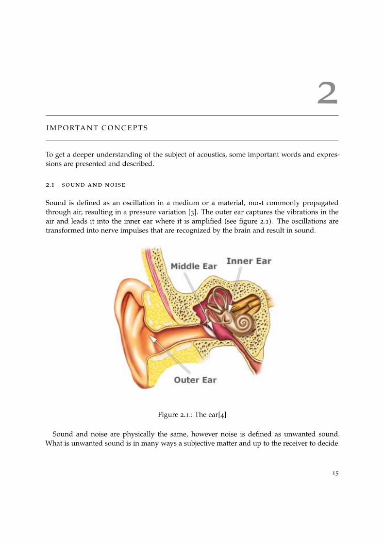
Sound is defined as an oscillation in a medium or a material, most commonly propagatedthrough air, resulting in a pressure variation [3]. The outer ear captures the vibrations in theair and leads it into the inner ear where it is amplified (see figure 2.1). The oscillations aretransformed into nerve impulses that are recognized by the brain and result in sound.
Figure 2.1.: The ear[4]
Sound and noise are physically the same, however noise is defined as unwanted sound.What is unwanted sound is in many ways a subjective matter and up to the receiver to decide.
15

16 important concepts
To help define unwanted noise, WHO [5] has made some measurements that can be used asguidelines. For example, the background noise should be at least 15 dB lower than speech tobe able to get full speech intelligibility. Normal speech is around 60 dB, which means that asound level of 75 dB can be disturbing and affect speech intelligibility. Speech intelligibility isa measure of how comprehensible speech is and can be affected by speech clarity as well asprecision.
2.2 sound pressure level (spl)
Because the ear is sensitive to pressure variations in the air it is appropriate to describe soundby using the term sound pressure or acoustic pressure which has a linear scale with theunit Pascal [3]. However, since the human ear can perceive sound pressures at both verylow and very high levels this makes it inconvenient to use a linear scale. Therefore, anothermeasurement known as the sound pressure level (SPL), or sound level, is used. This is alogarithmic measurement that gives the ratio to the standard reference level. The standardreference level is set at the sound pressure 20 µPa and the frequency 1000 Hz, which a healthyindividual can barely hear. This is also known as the threshold for human hearing, whichusing the decibel scale corresponds to 0 dB. The correspondence between sound pressurelevel and sound pressure is further explained in figure 2.2. Decreasing the SPL by 3 dB isequivalent to halving the sound pressure.
Figure 2.2.: Correspondence between sound pressure level (SPL) and sound pressure (SP)

2.3 frequency and amplitude 17
2.3 frequency and amplitude
Whether a tone is perceived as a high pitch or a low pitch depends on how fast the pressurechange is [3]. The speed of the pressure change is measured in the number of periods persecond and is called frequency. If the tone is high pitched the pressure change is fast, (a shortwavelength) resulting in a high frequency. Similarly, for the low pitch tone the pressure changeis slower, resulting in a lower frequency (figure 2.3).The human ear can hear frequenciesbetween 20 Hz 20 000 Hz. On the other hand, whether a tone is perceived as strong or weakdepends on the amplitude of the signal (figure 2.3).
Figure 2.3.: Frequencies and amplitudes contra the perception of sound. Inspiration from [6]
2.4 frequency band
Different types of sound insulation is effective for different frequencies [3]. As a sound con-sists of a various amount of frequencies, an analysis of the frequency spectrum in a soundenvironment can give the tools to provide the right sound insulation. When investigatingwhat frequencies a sound contains, it can be divided in frequency bands. An "octave" means
18 important concepts
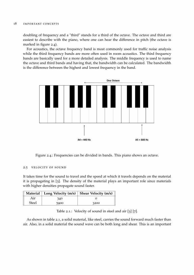
doubling of frequency and a "third" stands for a third of the octave. The octave and third areeasiest to describe with the piano, where one can hear the difference in pitch (the octave ismarked in figure 2.4).
For acoustics, the octave frequency band is most commonly used for traffic noise analysiswhile the third frequency bands are more often used in room acoustics. The third frequencybands are basically used for a more detailed analysis. The middle frequency is used to namethe octave and third bands and having that, the bandwidth can be calculated. The bandwidthis the difference between the highest and lowest frequency in the band.
Figure 2.4.: Frequencies can be divided in bands. This piano shows an octave.
2.5 velocity of sound
It takes time for the sound to travel and the speed at which it travels depends on the materialit is propagating in [3]. The density of the material plays an important role since materialswith higher densities propagate sound faster.
Material Long Velocity (m/s) Shear Velocity (m/s)Air 340 0
Steel 5900 3200
Table 2.1.: Velocity of sound in steel and air [3] [7].
As shown in table 2.1, a solid material, like steel, carries the sound forward much faster thanair. Also, in a solid material the sound wave can be both long and shear. This is an important

2.6 properties of a single wall and a double wall 19
factor to take under consideration when building a house. For example a steel beam runningthrough an insulation material can create an audio bridge.
2.6 properties of a single wall and a double wall
A single wall is defined as a wall that consists of one layer, for example a concrete wall. Whenair borne sound hits a wall, bending waves will occur [3]. This type of wave gives the particlesboth long, shear and rotational movement. The insulating properties of the wall is basically de-pendent on the walls ability to resist the bending waves as this prevents the air borne sound topropagate. For lower frequencies, the walls spring stiffness will be the physical phenomenonthat mainly affects the walls insulating ability. This is called the zero-mode-range. If the fre-quency increases slightly, mass and spring stiffness interacts which will result in resonancesat some frequencies. The frequency range with the first resonance frequencies is called thefew-mode-range and this is the behaviour that light weight constructions often shows. As thefrequency increases, the resonances become more frequent. However, higher frequencies leadsto faster pressure fluctuations which in turn makes it harder to move the wall. In conclusion,the resonances will not show in the curve and the sound pressure-frequency dependency willbe linear in this frequency range. This frequency range is called the multi-mode-range. Thesingle walls behaviour is described in figure 2.5.
Figure 2.5.: Principle sketch of the sound reduction/frequency dependence for a single wall[3]. The few-mode range is typical for light weight constructions and the multi-mode range is typical for heavy constructions.

20 important concepts
A double wall is defined as two plates that are separated with air, mineral wool or someother type of filling material. This is a technique that is used to be able to build lighterconstructions without loosing the sound insulating properties. At very low frequencies, thedouble wall will have the same behaviour as the single wall but as frequency increases theboth walls will start to work as two separate masses, connected with a spring whose stiffnessis decided from the air or filling material in the cavities. This system also have resonancefrequencies where the mass and spring coexists which gives the wall a significantly loweredinsulating ability here. This can however be improved with for example mineral wool thattransforms the sound energy into heat. At even higher frequencies the double wall starts tobehave as two separate single walls which gives double sound reduction. The double wallsbehaviour is visually described in figure 2.6.
Figure 2.6.: The sound reduction for a double wall with and without insulation in the cavities.As a reference, a single wall with the same weight as the double wall is also plotted[3].
2.7 sound classification
The Swedish building standard contains regulations for new constructions as well as for addi-tions/changes of existing buildings [3]. The standard have four different sound classifications,A,B, BBR and D where sound classification A and B corresponds to very good acoustic con-ditions and BBR is the minimum standard for Swedish housing [8]. Class D is meant to beused if sound classification can’t be achieved, for example during renovation. The soundclassification limits are presented in table 2.2.

2.8 defining sound insulation performance 21
Sound Class A B BBR DAirborne Sound Insulation (D′nT,w + C50−3150) 60 56 52 48
Impact Sound Insulation (L′nT,w + CI,50−2500) 48 52 56 60
Table 2.2.: Sound classifications described in dB [9]
2.8 defining sound insulation performance
In Swedish housing there are regulations saying a certain amount of soundproofing has to bemaintained to diminish noise such as those from neighbors or roads [3]. The sound insulationcan be measured by using weighted values [8]. The weighted values summarizes the perfor-mance of the building element (for example a floor) in one single value. For airborne sound,the weighted value is expressed as a sound reduction index (which means that a high valueindicates good sound insulation). For impact sound, the sound insulation is described as aweighted value indicating the impact sound level (resulting in a lower value indicating goodimpact sound insulation).
2.9 flanking transmission
The isolating ability of a partition wall is not only dependent on its own characteristics. Soundcan also transmit via the flanking walls (figure 2.7). This type of sound transmission is calledflanking transmission and to minimize it, well executed junctions are crucial. The flankingtransmission is important to take into account to get the best sound reduction from the parti-tion wall.
Figure 2.7.: Flanking transmission. Inspired by [3]

22 important concepts
2.10 absorption
When a sound wave hits an object or material one part of the wave reflects and one partabsorbs [3]. This can be described with equation 2.1 where Πi is the incoming sound effect,Πr is the reflecting sound effect and Πa is the absorbed sound effect.
Πi = Πr + Πa (2.1)
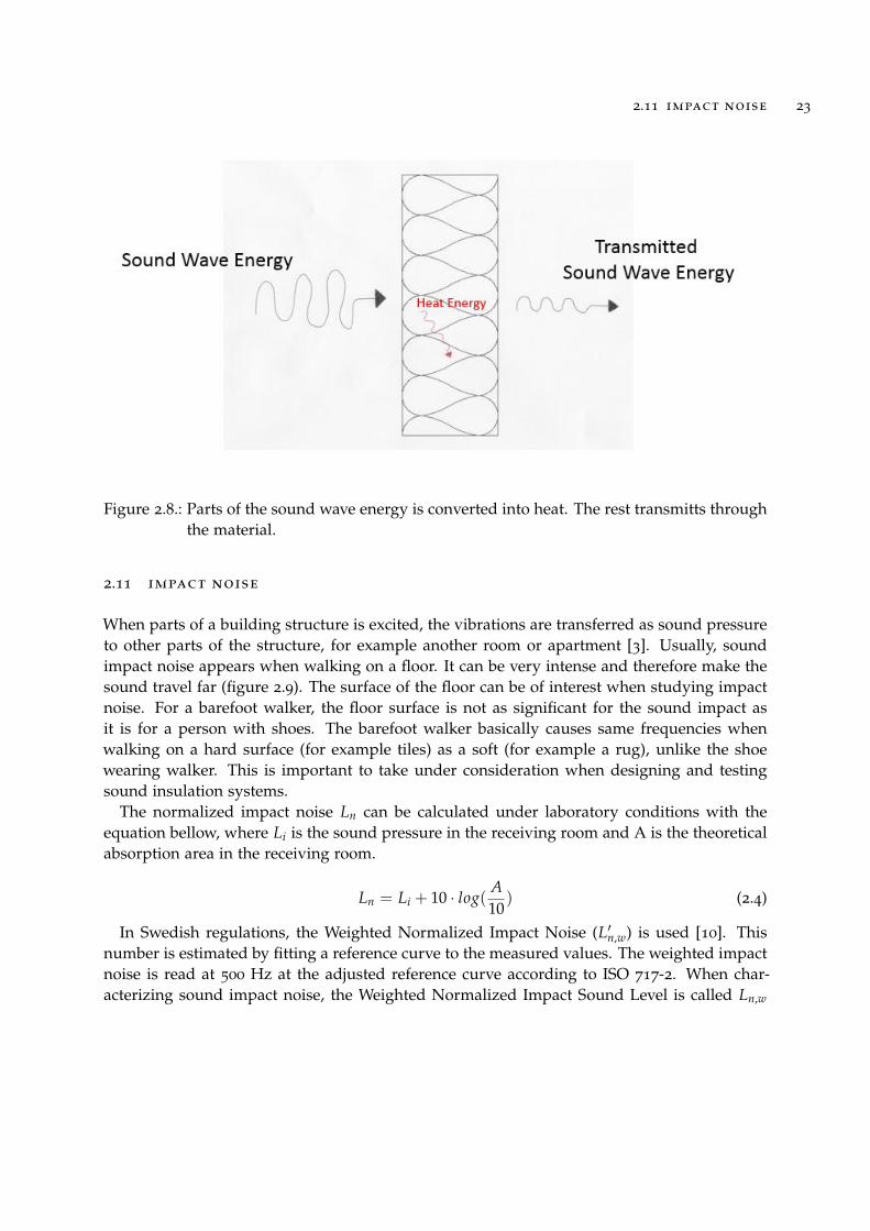
One part of the absorbed sound wave energy converts to heat energy and the rest transmitsthrough the material or object (see figure 2.8). A materials sound absorbing properties aredefined by the absorption coefficient (α) which gives the share of the sound effect that ab-sorbs (see equation 2.2). The absorption coefficient ranges from 0 (total reflection) to 1 (totalabsorption).
α =Πa
Πi(2.2)
The absorption area (A) gives a partial area, with α = 1, that corresponds to the sameabsorption that the actual absorbing surface (S) will give. In conclusion: A is a theoreticalarea while S is the actual area that can be measured in a room. The absorption area can bedescribed with equation 2.3 and an example follows bellow to further describe the concept.
A = α · S (2.3)
An absorbent, say a curtain, with α = 0.5 and S = 5 m2 will have an absorption area of0.5·5=2.5 m2. This means that 2.5 m2 of an absorbent with α = 1 (this corresponds to a 2.5 m2
open window) will give the same absorption that 5 m2 of the original absorbent (the curtain).
2.11 impact noise 23
Figure 2.8.: Parts of the sound wave energy is converted into heat. The rest transmitts throughthe material.
2.11 impact noise
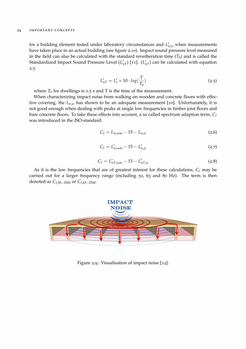
When parts of a building structure is excited, the vibrations are transferred as sound pressureto other parts of the structure, for example another room or apartment [3]. Usually, soundimpact noise appears when walking on a floor. It can be very intense and therefore make thesound travel far (figure 2.9). The surface of the floor can be of interest when studying impactnoise. For a barefoot walker, the floor surface is not as significant for the sound impact asit is for a person with shoes. The barefoot walker basically causes same frequencies whenwalking on a hard surface (for example tiles) as a soft (for example a rug), unlike the shoewearing walker. This is important to take under consideration when designing and testingsound insulation systems.
The normalized impact noise Ln can be calculated under laboratory conditions with theequation bellow, where Li is the sound pressure in the receiving room and A is the theoreticalabsorption area in the receiving room.
Ln = Li + 10 · log(A10
) (2.4)
In Swedish regulations, the Weighted Normalized Impact Noise (L′n,w) is used [10]. Thisnumber is estimated by fitting a reference curve to the measured values. The weighted impactnoise is read at 500 Hz at the adjusted reference curve according to ISO 717-2. When char-acterizing sound impact noise, the Weighted Normalized Impact Sound Level is called Ln,w
24 important concepts
for a building element tested under laboratory circumstances and L′n,w when measurementshave taken place in an actual building (see figure 2.10). Impact sound pressure level measuredin the field can also be calculated with the standard reverberation time (T0) and is called theStandardized Impact Sound Pressure Level (L′nT) [11]. (L′nT) can be calculated with equation2.5.
L′nT = L′i + 10 · log(TT0
) (2.5)
where T0 for dwellings is 0.5 s and T is the time of the measurement.When characterizing impact noise from walking on wooden and concrete floors with effec-
tive covering, the Ln,w has shown to be an adequate measurement [10]. Unfortunately, it isnot good enough when dealing with peaks at single low frequencies in timber joist floors andbare concrete floors. To take these effects into account, a so called spectrum adaption term, CI
was introduced in the ISO-standard:
CI = Ln,sum − 15− Ln,w (2.6)
CI = L′n,sum − 15− L′n,w (2.7)
CI = L′nT,sum − 15− L′nT,w (2.8)
As it is the low frequencies that are of greatest interest for these calculations, CI may becarried out for a larger frequency range (including 50, 63 and 80 Hz). The term is thendenoted as CI,50−2500 or CI,63−2500.
Figure 2.9.: Visualisation of impact noise [12].

2.12 tapping machine 25
2.12 tapping machine
When measuring impact sound noise in a building, a tapping machine is used [13]. Thetapping machine was originally developed to imitate the impact noise from high-heeled shoesand this can sometimes give misleading results as it is more common to be barefoot indoors, atleast in Swedish dwellings. The barefoot walker causes impact sound in the lower frequencyrange while the high-heel gives frequencies in the higher frequency range. There are otherinstruments on the market developed for low frequency measurements, for example lettinga rubber tire or ball fall to the floor. However, using the tapping machine is of internationalstandard and most commonly used when investigating impact sound. The tapping machineshould therefore in first hand be used. Sound transmission differs between the laboratorycase and field situation [11]. In the laboratory case, the test specimen is often structurallyseparated from the primary construction, hence there are no vibrations travelling throughwalls and such (figure 2.10). Although flanking transmission has an impact, it’s normally agreater problem when dealing with air-borne sound.
Figure 2.10.: Difference between a laboratory case (left) and a field case (right) [11].
2.13 porous material
Building materials can be divided in two main categories: porous and compact [14]. In thefollowing sub chapter the porous material is further described. A porous material consistspartly of pores and partly of compact mass. Examples of porous materials can be concrete,wood or mineral wool. The porosity is of importance for a materials strength and also for amaterials heat insulating properties. The insulating properties are the main reason for mineralwool to be a common material to use in most types of building constructions but it also have

26 important concepts
sound insulting properties. This is due to the porosity of the material that forces an interactionbetween air and wool fibres [9]. The porous structure is forcing the sound pressure waves totravel a longer distance resulting in a damping effect from friction at the surface of the fibres.
2.14 lightweight aggregate
A light weight aggregate can be defined as a coarse granular material. By definition thegranular structure means collections of many macroscopic solid grains [15]. The differencebetween granule and grain is described in figure 2.11. In this thesis the grains are made fromglass wool residue but in general the grains can be anything from rice to gravel.
Figure 2.11.: The difference between "grain" and "granular".
2.15 standards and building regulations
In the last years, the interest for building light weight timber constructions have increased,which sets new demands on the current national building regulations [16]. When building ahouse, one must take into account the rules and restrictions that apply in the current coun-try. The building restrictions exist to specify minimum requirements and as all regulationsusually are based on international standards, they tend to bear many similarities. However,all countries usually have additional rules, which are a result of their traditions in buildingtechnique.
2.15 standards and building regulations 27
Swedish housing regulations are based on PBL (Plan- & Bygglagen) but BBR (BoverketsByggregler) is the regulatory code that provides the practical application of the laws [17]. BBRtherefore becomes the document used for more detailed information and advice. The chapterconcerning noise insulation covers both airborne and impact noise. The general requirementsays that buildings shall be constructed in a way that limits the occurrence and spread ofnoise. The maximum impact noise level recommended from BBR is 56 dB (sound classificationBBR) and this level is valid for outside noise coming inside dwellings. More details andcircumstance cases can be found in BBR.
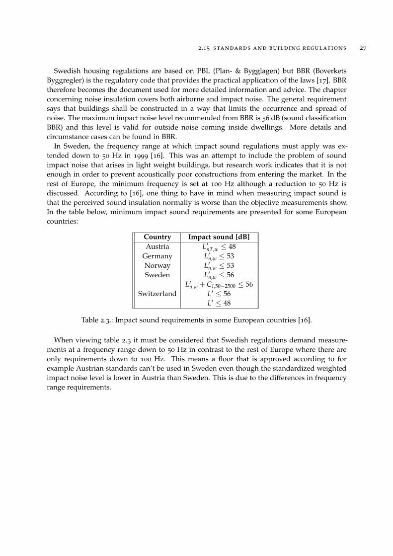
In Sweden, the frequency range at which impact sound regulations must apply was ex-tended down to 50 Hz in 1999 [16]. This was an attempt to include the problem of soundimpact noise that arises in light weight buildings, but research work indicates that it is notenough in order to prevent acoustically poor constructions from entering the market. In therest of Europe, the minimum frequency is set at 100 Hz although a reduction to 50 Hz isdiscussed. According to [16], one thing to have in mind when measuring impact sound isthat the perceived sound insulation normally is worse than the objective measurements show.In the table below, minimum impact sound requirements are presented for some Europeancountries:
Country Impact sound [dB]Austria L′nT,w ≤ 48
Germany L′n,w ≤ 53Norway L′n,w ≤ 53Sweden L′n,w ≤ 56
L′n,w + CI,50−2500 ≤ 56Switzerland L′ ≤ 56
L′ ≤ 48
Table 2.3.: Impact sound requirements in some European countries [16].
When viewing table 2.3 it must be considered that Swedish regulations demand measure-ments at a frequency range down to 50 Hz in contrast to the rest of Europe where there areonly requirements down to 100 Hz. This means a floor that is approved according to forexample Austrian standards can’t be used in Sweden even though the standardized weightedimpact noise level is lower in Austria than Sweden. This is due to the differences in frequencyrange requirements.


3
T H E N E W M AT E R I A L S
Ecophon are developing two new granular materials with different grain sizes, giving thetwo aggregates different possible applications. the materials can be viewed in figure 3.1 - 3.2This chapter is a short summary of the report on LWA 2 (the smaller granules) that Ecophonordered from Saint-Gobain Research center earlier in 2015, interviews with Emma Arvidssonfrom Ecophon and measurements done in Ecophons laboratory. The two granular materialsare described, but as they are still in a developing process there are information gaps. Cur-rently, the information on LWA 1 is incomplete in different areas, which is why all parameterscannot be accounted for both materials.
3.1 description of lwa 1
Originally, LWA 1 is a way to process the glass wool residue in order to send it to landfillswhere it can be used as construction material [18]. The residue is processed to grains, usingprocess water from other production lines and cement. The proportions are roughly 10%cement, 15% process water and the rest is mineral wool residue. In this way, both glass woolresidue and process water is taken care of and a fairly small amount of new material (cement)is put in the process. The final product is a granular material with irregular sized grains.Necessary material parameters were measured in Ecophons laboratory and are presented intable 3.1.
29

30 the new materials
Parameter LWA 1 LWA 2Density (ρ) 1400 kg/m3
1000 kg/m3
Yong’s modulus (E) - 3 · 106
Poisson’s ratio (ν) - 0
Loss Factor (η) - 0.25
Porosity (Φ) 40% ± 1.2 %Resistivity (σ) 300± 97Nsm−4
6052 Nsm−4
Tortuosity (α∞) - 1.84
Viscous characteristic length (Λ) - 184 µmThermal characteristic length (Λ′) - 1.4 · 106 N/m
Table 3.1.: Summary of mechanical parameters for LWA 1 and LWA 2
3.2 description of lwa 2
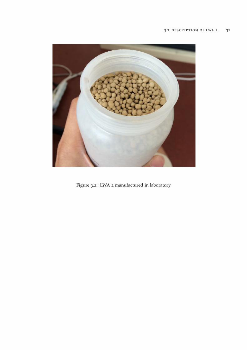
In contrary to LWA 1, LWA 2 are made from glass wool residue with a polymer binder insteadof cement [18]. So far, these light weight aggregates have only been manufactured in smallscale in laboratory environment. The grains have irregular size from 1-8 mm and a densityaround 1000 kg/m3 which makes it lighter than many other ballast materials (for examplegravel) but heavier than insulation materials such as mineral wool [19].
In the laboratory report carried out by [19], measured values are presented for both me-chanical and acoustical parameters. The results can be found here in table 3.1.
Figure 3.1.: LWA 1 used at a landfill in Landskrona
3.2 description of lwa 2 31
Figure 3.2.: LWA 2 manufactured in laboratory


Part II
M A R K E T S U RV E Y


4
I N V E S T I G AT I O N O F I N T E R M E D I AT E F L O O R S
In this chapter a market survey of intermediate floors is presented. The goal is to find floor-types where the new LWA’s can replace other sound insulation materials. The market surveyis carried out by free interviews with a number of building companies and also by studyingscience reports. The chapter is divided in different types of load bearing structures.
4.1 wood as load bearing structure
Using wood as load bearing structure is very common when building single family houses.In Sweden over 80% of all single family houses are made from wood [20].When it comes tomulti-family building it is not as common and stands for only about 10% today. But becauseof new fire regulations and increasing interest in renewable materials, the interest in timberframed buildings have increased. The technique is also well suited for industrial building andprefabricating building elements can speed up the building process.
Building with wood can be done with regular sawn timber but the material can also berefined in many ways [21]. When layers of wood are glued, or in some other way joined to asolid product, it is called Solid Wood. Intermediate floors made from this types of techniquessuch as CLT, Glulam, Box Elements and Volume Elements are presented in the following subchapters.
4.1.1 CLT
CLT (or Cross Laminated Timber) is a building technique where timber lamellas are glued inmultiple layers. Each lamella is perpendicular to its adjacent layer [21]. This technique resultsin an element being able to take load in two directions. CLT can be used as load bearingstructure in multistory buildings or smaller houses. The CLT floor can be a plate of solidwood or a cassette structure which can be insulated in various ways. Concrete can be used insome extent, for example as leveler. This gives the floor more stiffness that in turn leads toless low frequency sound transmission [1].
Examples of what materials can be used are presented in the bullet list below, in order fromfloor-top to inner-ceiling. The first three examples in the list are built in Switzerland andAustria, and the last example is a Swedish type solution. Figure 4.1 and 4.2 are type sketches
35

36 investigation of intermediate floors
and gives a general idea and visualization of what a CLT-floor can look like. A CLT slab couldbe replaced with Brettstapel. Brettstapel is another type of solid wood technique where noglue or nails are used, but instead the timber lamellas are joined with hard wood dowels [22].
• Floor covering, concrete leveler, impact sound insulation, cement panels, particle board,CLT [23]
• Floor covering, concrete leveler, impact sound insulation, layer of concrete on CLT orBrettstapel
• Floor covering, sound impact insulation, EPS Foam, concrete, PE-foil, CLT, mineral wooland gypsum that either can be installed directly on the CLT or alternatively as a sus-pended ceiling
• Floor covering, gypsum board, sound impact insulation, solid wood cassette structurefilled with mineral wool, structure to hold up a suspended ceiling with mineral wooland gypsum [24]
Figure 4.1.: General sketch of a CLT element [25]. The slab is covered with a layer of concretewith impact sound insulation layer on top.

4.1 wood as load bearing structure 37
Figure 4.2.: 2D model of a casette structure with inspiration from [24]
4.1.2 Box Elements
Box systems are prefabricated elements where solid wood plates are joined with crossing barsto create a slab element [26]. Box elements are usually filled with insulating material and/orballast to prevent sound to amplify (by reflection) inside the cavities. A ballast material givesmore stiffness to the floor and reduce vibrations.
In the bullet list, the first example is a multifamily house in Switzerland and the secondexample a type construction from a Swiss company that is focused on industrial productionof these types of floors. In figure 4.3 a type sketch of a box element floor slab is presented.
• Floor covering, concrete leveler, impact sound insulation, gypsum board, box elementfilled with ballast material [23]

38 investigation of intermediate floors
• Floor covering, particle board, sound impact insulation, Layer of honeycomb fill, Boxelement filled with ballast material [26]
Figure 4.3.: Example of box element floor slab with inspiration from [27]. This box elementis filled with ballast and there are three material layers (honeycomb fill, soundimpact insulation and screed) on top.
4.1.3 Glulam Beams
Glulam is a traditional technology with roots in the beginning of the 20th century [28].Defectsin the sawn wood such as knots, splits and sloping grain are randomly distributed throughoutthe beam allowing glulam to be designed to higher stresses than regular sawn wood of thesame grade. It also can be manufactured in a wide variety of shapes and sizes and beamswider than normally can be manufactured.
When designing an intermediate floor with glulam one can have beams as primary struc-ture, fill the cavities with insulation and put a floating floor with various layers of materials ontop to provide good insulation as well as stability. The layers vary from building to buildingbut examples are:
• Floor, cement leveling, impact sound insulation, cement board, particle board, beams ofGlulam [23]

4.1 wood as load bearing structure 39
• Combine beams of glulam with a solid wood board in the bottom of the floor slab,creating something similar to a box element. The cavities are filled with mineral wooland on top of the bearing structure one can install a floating floor on an elastomer. Thefloating flor can consist of various layers of gypsum and particle boards
• Mineral Wool between beams and floating floor of particle board and gypsum installedon an elastomer to dampen out vibrations [29]
The first two examples in the bullet list above are from Switzerland and the last one is aSwedish construction. Figure 4.4 shows an example of what a glulam construction can looklike.
Figure 4.4.: Example of a glulam floor [30]. Stratigraphy from the top: sand, sound impactinsulation board, particle board, glulam beams with mineral wool and two layersof gypsum.
4.1.4 Volume Elements
In modern building industry, the interest of prefabricating building elements has increased inrecent years [1]. Volume elements are a building technique where larger building elementsare assembled at a factory. This makes the building process less sensitive to weather and givesa more secure quality control. The volume elements are assembled at the construction site.

40 investigation of intermediate floors
Figure 4.5 and 4.6 shows a general sketch of a volume element building and a detailed designof a joint.
Figure 4.5.: The volume elements are prefabricated and assembled at the construction site.In order to prevent sound transmission between elements, an elastomer is putbetween the elements. [1]
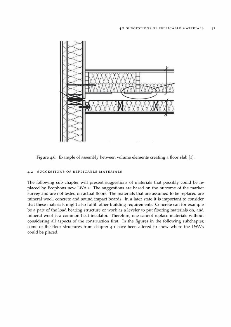
Transfer of structure borne sound can be avoided by mechanically separating the volumesi.e. leaving space between ceiling and floor of adjacent volumes (see figure 4.6). With this typeof design, impact sound can only be transferred through the flanks but this can be reduced byplacing an elastomer at the edges of the volume. These layers must be dimensioned for thespecific weight that is put on the elastomer, meaning that it is of importance to consider theincreasing load far down the building. This phenomenon is described in figure 4.5. Volumeelements are common in both Sweden and Norway where a construction could have thefollowing layers [23]:{
Upper element: particle board, glulam beams with mineral wool
Lower element: mineral wool between beams, gypsum board
4.2 suggestions of replicable materials 41
Figure 4.6.: Example of assembly between volume elements creating a floor slab [1].
4.2 suggestions of replicable materials
The following sub chapter will present suggestions of materials that possibly could be re-placed by Ecophons new LWA’s. The suggestions are based on the outcome of the marketsurvey and are not tested on actual floors. The materials that are assumed to be replaced aremineral wool, concrete and sound impact boards. In a later state it is important to considerthat these materials might also fulfill other building requirements. Concrete can for examplebe a part of the load bearing structure or work as a leveler to put flooring materials on, andmineral wool is a common heat insulator. Therefore, one cannot replace materials withoutconsidering all aspects of the construction first. In the figures in the following subchapter,some of the floor structures from chapter 4.1 have been altered to show where the LWA’scould be placed.

42 investigation of intermediate floors
4.2.1 CLT
In the case where the CLT is designed as a solid slab element, con-crete leveler might be replaced with LWA 2 as these have smallergranule size and can create a relatively plane surface.
4.2 suggestions of replicable materials 43
4.2.2 Box Elements
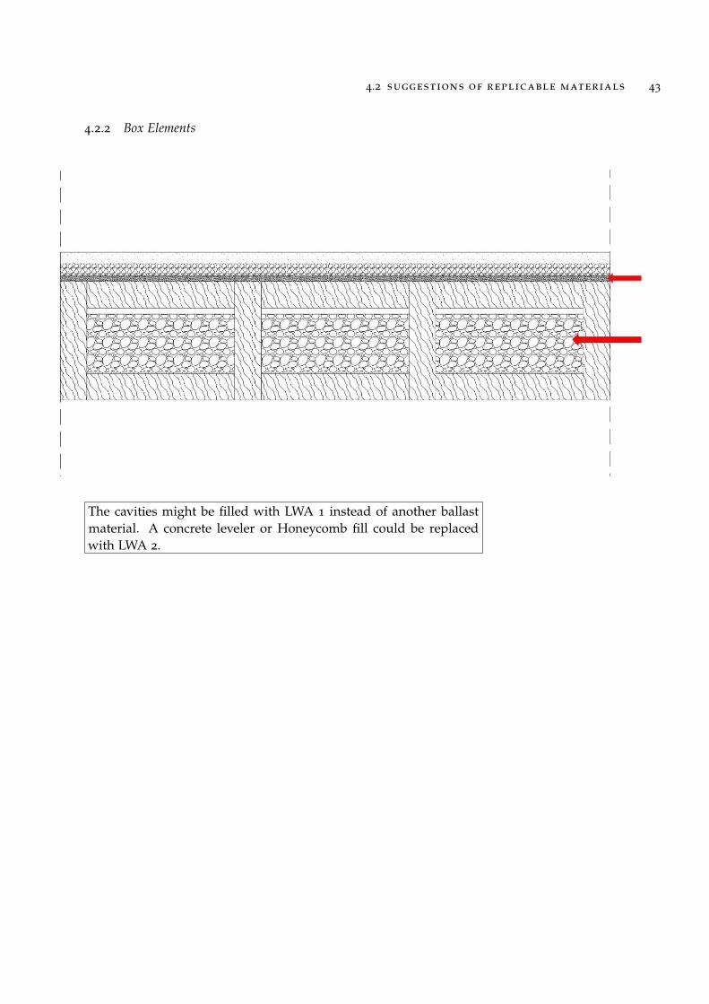
The cavities might be filled with LWA 1 instead of another ballastmaterial. A concrete leveler or Honeycomb fill could be replacedwith LWA 2.

44 investigation of intermediate floors
4.2.3 Glulam
Parts or all mineral wool in cavities could be replaced with LWA 1.

4.2 suggestions of replicable materials 45
4.2.4 Cassette elements
In the case with the cassette structures, a granule material seemsdifficult to use as filling inside the load bearing structure. Basicallyone can assume that the granules will need a well defined spaceto be able to stay in place. This is however possible to solve, forexample by putting a particle board on the bottom of the cassette,creating a defined space for the granules.


5
E C O N O M Y
This chapter is a short of the market survey where possible costs of traditional building mate-rials commonly used in intermediate floors, are investigated. The goal is to be able to presenta price span where the new LWA’s needs to be in order to be competitive in the market.
The market survey revealed some materials that seems to be common as impact soundinsulators:
• Mineral wool
• Ballast materials
• Concrete
Interviews with the builders’ merchant Optimera [31] and the mineral wool manufacturerIsover [32] gave a general idea of how, and where companies buy their material. The con-clusion is that larger building companies buy materials both from builder’s merchants anddirectly from factories but usually they have special agreements giving them discounts forbuying large amounts. The extent of these discounts are not a public matter, however it willbe tested in a hypothetical example bellow. The discount in this example is not based on theabove mentioned interviews, but was discussed with the supervisors at Ecophon.
Price examples of material costs are retrieved from Wikelks Byggbeärkningar [33] and pre-sented in the table below.
Material Layer Thickness (mm) Builders’ merchantPrice (SEK/m2)
Mineral Wool 95 44
Concrete 100 126
Gravel 100 96
Table 5.1.: Price levels for an approximate layer size of 100 mm for mineral wool, concrete andgravel [33]
As mentioned above, larger building companies usually have discounts when buying largeamounts. As an experiment, a 50% discount was applied to see what price levels this resultedin (see table 5.2)
47

48 economy
Material Layer Thickness (mm) Price afterdiscount (SEK/m2)
Mineral Wool 95 22
Concrete Leveler 100 63
Gravel 100 48
Table 5.2.: Price levels for the materials mentioned in 5.2 after a 50 % discount
As the discount levels are not a public matter, this calculation can only be seen as an esti-mation but it gives an indication of the market with the conclusion being that depending onwhat type of material the new LWA’s will replace, and if discounts are applied or not, theprice level can range from ∼20 SEK to ∼ 120 SEK.
6E N V I R O N M E N TA L A S P E C T S
There is a globally increasing interest for environmental issues leading the construction indus-try to take interest in sustainable building. The demands from EU increases when it comesto for example energy efficiency and material use [17]. The following chapter is based on aninterview with Ecophons environmental specialist Anna Palminger [34].
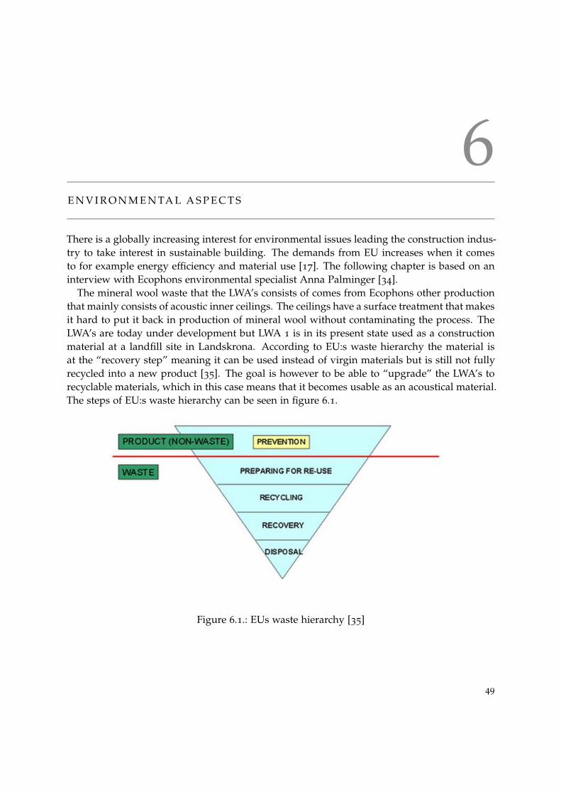
The mineral wool waste that the LWA’s consists of comes from Ecophons other productionthat mainly consists of acoustic inner ceilings. The ceilings have a surface treatment that makesit hard to put it back in production of mineral wool without contaminating the process. TheLWA’s are today under development but LWA 1 is in its present state used as a constructionmaterial at a landfill site in Landskrona. According to EU:s waste hierarchy the material isat the “recovery step” meaning it can be used instead of virgin materials but is still not fullyrecycled into a new product [35]. The goal is however to be able to “upgrade” the LWA’s torecyclable materials, which in this case means that it becomes usable as an acoustical material.The steps of EU:s waste hierarchy can be seen in figure 6.1.
Figure 6.1.: EUs waste hierarchy [35]
49

50 environmental aspects
Being able to recycle mineral wool residue can provide significantly lowered GWP’s (GlobalWarming Potential) and of course also lowered waste production for Ecophons other mineralwool based products, as they are so called passive products (i.e. most environmental impactare in production stage and waste stage). This can be applied on all of Ecophons currentEPD’s, resulting in products with less GWP and less waste production.
Green building certification systems such as LEED and BREEAM can motivate buildingcompanies to choose alternative materials to improve their certification scores. It is howevernot for certain that one can raise their scores in such certification systems by replacing insu-lation materials in floor structures, this depends on how the score-system is designed. Forexample, insulation materials are excluded from the evaluation criterias in BREEAM [36]. InLEED, the rule applied is that one needs a certain amount (10 or 20 %) of recycled material inthe entire building to require scores for using recycled materials [37]. The sound insulation inintermediate floors only stands for a small part of a building and therefor one will probablynot be able to get scores in LEED just by using the new LWA’s. To know for certain if the newLWA’s could be advantageous when certifying a building, various certification systems mustbe more closely investigated. This is however not the aim for this thesis.

Part III
C A L C U L AT I O N S


7
F I N I T E E L E M E N T M O D E L L I N G
A floor will be modelled with the finite element method. A parametric study will be carriedout where comparisons between traditional materials and the new LWA’s are made.
7.1 introduction to the finite element method
Solving engineering problems can often result in differential equations that is too compli-cated to be solved by classical analytical methods [38].The finite element method (FEM) isa commonly used numerical method that consists of approximate general differential equa-tions. The differential equations can describe physical problems (for example acoustic soundpropagation) that holds over a region that can be one- two- or three-dimensional. But insteadof trying to find an approximation that holds for the entire region, it is divided into smallerparts, so-called finite elements. The collection of finite elements in a region is called a mesh.The behavior for each element is approximated and a solution for the behavior of the entireregion can then be obtained by assembling the elements into a global system.
When deriving a finite element problem, the system is transformed from having infinitelymany unknowns (degrees of freedom) to having a finite number of unknowns. Problemsthat are solved with FEM generally have thousands of degrees of freedom and can only becalculated with a computer. The amount of degrees of freedom is governed by the number ofelements in the region. Creating a finer mesh gives a more accurate result, but at the cost ofincreased time to solve the problem.
7.2 design
To make calculations, a simple floor model is chosen. This is partly to simplify the mesh andpartly to have a basic standard at which one easily could add more to. It consists of glulambeams (56mmX270mm) with cc 600mm, a bottom plate of particle board and a gypsum boardon top. Measurements can also be found in figure 7.3. The market survey carried out inchapter 4 indicates that this type of frame is common, even though it usually is combinedwith a floating floor and/or a suspended ceiling to achieve the requirements.
53

54 finite element modelling
Figure 7.1.: The floors structure.
Figure 7.2.: General explanation of the finite element method.

7.3 aim for calculations 55
7.3 aim for calculations
The main aim for the calculation model is to find out how the new LWA’s react at low fre-quencies (<125 Hz), meaning at what frequencies it can absorb sound. It is assumed that thechosen floor type is best suited for LWA 1, which is why the calculations are limited to thismaterial and LWA 2 is left out. This is based on the outcome of the market survey, wherecoarser ballast is used when filling out cavities in intermediate floors. A parametric studyis carried out where a reference floor (with only air in the cavities) is compared to a num-ber of possible cases where the cavities are filled with various amounts of mineral wool andLWA’s. The reason to also test the structure with a combination of mineral wool and LWAis because mineral wool is a commonly used insulation material, and will probably be a partof any insulation solution as it absorbs sound at higher frequencies. Finally the outcome ofthe calculations will be compared to laboratory measurements done by the consulting firmAkustikverkstan.
Figure 7.3.: A sketch of the floor slab with measurements.

56 finite element modelling
7.4 modelling a floor in abaqus
The following subchapters will bring up the modelling in Abaqus and necessary validationsof the model. There is also a section where some material parameters have been altered inorder to later discuss possible alternations of the materials.
7.4.1 Defining materials in Abaqus
As mentioned above, the floor consists of various types of materials that needs to be definedin Abaqus. The frame consists of structural materials that are defined by density, Poisson’sratio, elastic- and shear modulus depending on if the material is isotropic or orthotropic (seetable 7.1 and 7.2).
Material ρ kg/m3 E (Mpa) ν (-)Gypsum Board 650 29500 0.13
Particle board 750 340 0.08
Table 7.1.: Material parameters used for isotropic materials [39]
ρ E1 E2 E3 G12 G13 G23 ν12 ν13 ν23
380 9040 790 340 640 580 30 0.5 0.66 0.84
Table 7.2.: Material parameters used for the glulam beams. Wood is considered a orthotropicmaterial [40]. ρ is given in kg/m3 and E and G in MPa.
The acoustical materials are defined as acoustic fluids 1 by density, bulk modulus and volu-metric drag. The bulk modulus (K0) is calculated according to [9] as
K0 = ρair · cair = 141826 (7.1)
where ρair = 1.184 kg/m3 and cair = 346.1 m/s [39]. The volumetric drag (γ) was calculatedaccording to [41] as
γ = σ ·Φ (7.2)
where σ is the flow resistivity and Φ is the porosity [42] (see table 7.3).
1 Both mineral wool and LWA will be defined as porous materials. This is an approximation and will not give quiteexact calculations but it is a fair approximation

7.4 modelling a floor in abaqus 57
Acoustic material σ (Nsm−4) Φ(−) ρ (kg/m3)
Mineral Wool 9000 0.99 16
LWA 1 266 0.37 1400
Table 7.3.: Material parameters used for acoustical materials [42]
7.4.2 Workflow for Abaqus
Five separate parts where created: long beams, short beams, bottom plate, top plate, andfilling. The four first parts where assembled, creating a frame with five compartments (figure7.4). To assemble the parts (for example the gypsum board with the beams), partitions had tobe made to be able to choose the specific surfaces involved (figure 7.5). When assembling twoparts one must choose a master/slave relation. When dealing with this type of construction,this had to be done in the right order because if a surface is chosen to be slave, Abaqus erasesall nodes at this surface. If the slave later is chosen as master to another part, there are nonodes left to be tied to the surface. There are no specific rules in how to make the boundbetween surfaces but in this case the frame was first assembled, choosing the plates to bemaster surfaces. Then all of the inside of the frame was tied to the filling (air or insulation)that was set to slave. Finally, the filling was partitioned in three layers to make alternationsbetween different combinations of filling materials possible.

58 finite element modelling
Figure 7.4.: The frame modelled in Abaqus. The upper image shows the frame of beams andthe lower image shows both beams and plates assemled creating the enire frame.

7.4 modelling a floor in abaqus 59
Figure 7.5.: The plate is partitioned, making assembling possible.
60 finite element modelling
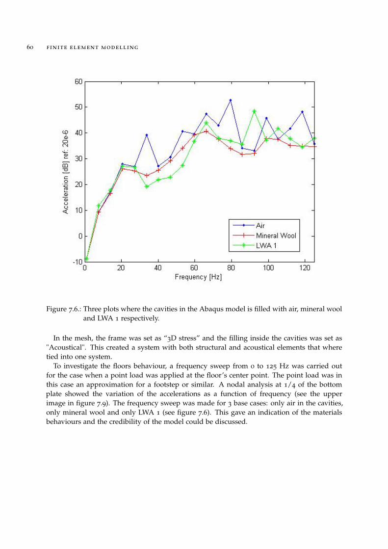
Figure 7.6.: Three plots where the cavities in the Abaqus model is filled with air, mineral wooland LWA 1 respectively.
In the mesh, the frame was set as “3D stress” and the filling inside the cavities was set as"Acoustical". This created a system with both structural and acoustical elements that wheretied into one system.
To investigate the floors behaviour, a frequency sweep from 0 to 125 Hz was carried outfor the case when a point load was applied at the floor’s center point. The point load was inthis case an approximation for a footstep or similar. A nodal analysis at 1/4 of the bottomplate showed the variation of the accelerations as a function of frequency (see the upperimage in figure 7.9). The frequency sweep was made for 3 base cases: only air in the cavities,only mineral wool and only LWA 1 (see figure 7.6). This gave an indication of the materialsbehaviours and the credibility of the model could be discussed.

7.4 modelling a floor in abaqus 61
7.4.3 Validation of the Model
The model was validated by choosing nodes form half of the plate (figure 7.9) and extend thefrequency sweep from 0-125 Hz to 0-200 Hz. The results from the validation are plotted inAbaqus (see figure 7.7)
Figure 7.7.: It is validated that the Abaqus model gives the same result for half of the plate asfor one fourth of the plate.
Another part of the model that needed validation was the tie between the mineral wool andthe top plate. The simulations where made both for the case where the mineral wool was tieddirectly to the top plate and for the case where a 3mm air gap between mineral wool and topplate was added. In figure 7.8 one can see that the air gap makes no significant differencefor the results and therefor the simplest case for a given calculation will be used. This meansthat the filling will be directly tied to the gypsum board for the case where the entire cavity isfilled.

62 finite element modelling
Figure 7.8.: Cavities in the floor are filled with mineral wool. The blue plot shows the casewhere the mineral wool is tied to the top plate. The red plot shows the case wherethere is a 3mm air gap between the mineral wool and the top plate.
After the model was validated the materials could be combined. A three-layer combinationof air, mineral wool and LWA 1 was tested and the layer thicknesses was altered to find outa suitable combination. Three layer thicknesses of LWA 1 was tried out but the mineral woollayer was constant at 100 mm.

7.4 modelling a floor in abaqus 63
Figure 7.9.: For validation, nodes from half the plate is chosen to find out if it gives the sameresult as if one fourth of the nodes are chosen.

64 finite element modelling
7.4.4 Alternation of Material Parameters
As the LWA’s are under development, there are still a possibility to alter the material parame-ters to optimize it for the floor insulation application. The volumetric drag (see equation 7.2)was altered to see indications of improvement or deterioration. The volumetric drag for LWA1 was very low to begin with so the parameter was significantly increased to see if this gaveany differences in acceleration. The increase could for example correspond to a flow resistivityof ∼ 7000Nsm−4 and a porosity of ∼ 60%. The density was altered to 2400 kg/m3 which isapproximately the same as concrete.
7.5 comparing results
The simulation results from Abaqus consists of accelerations in nodes at the bottom plate at20 frequencies between 0 and 125 Hz. In order to compare different simulations and be ableto draw conclusions, this data must be analyzed. In the following subchapters the conversionfrom accelerations to sound pressure levels (that are comparable with measurements) arepresented. The workprocess is described in figure 7.10.
Figure 7.10.: The simulation results are exported from Abaqus as accelerations and recalcu-lated to sound pressure levels with respect to the dimensions of the laboratory atAkustikverkstan. This gave comparable results.

7.5 comparing results 65
7.5.1 Comparing Abaqus Simulation Results
The data was exported from Abaqus and analysed in Matlab (see code example in appendixA). All accelerations where redefined as RMS-values according to [9] and this made it possibleto compare different cases in the same plot:
αRMS( f ) =
√1n
n
∑i=1
a( f )2 (7.3)
7.5.2 Comparing Abaqus Simulation Results With Measurments
In order to compare calculations with earlier measurements done by Akustikverkstan, theaccelerations had to be recalculated into sound pressure 2 using relations from equation 7.4.
pv= ρ · c (7.4)
where p is the sound pressure in Pa, v is the particle velocity in m/s, ρ is the density inkg/m3 and c is the velocity of sound in the medium (in this case the medium being air) in m/s.Eigenmode frequencies for the room (meaning the receiving room at Akustikverkstans labo-ratory) where found using equation 7.5. These frequencies where paired with correspondingsound pressure from the Abaqus simulations.
f =c2
√(
nx
L)2 + (
ny
W)2 + (
nz
H)2 (7.5)
2 This is not an exact comparison as the floor tested at Akustikverkstan has a different structural design.

66 finite element modelling
Figure 7.11.: Principle sketch showing the measurements of the recieving room of the labora-tory at akustikverkstan
The eigenmodes where calculated with respect to the room measurements of the laboratoryat Akustikverkstan (see figure 7.11) where previous measurements have been made. Theresults from the actual measurements are presented in figure 7.12.
Finally, the sound pressures where described as SPL’s using equation 7.6
Lp = 10 · log(p̃2
k · p2re f
) (7.6)
where k is the number of modes, p̃ is the RMS-value of the sound pressure and Pre f is thereference value 20 µPa.

7.5 comparing results 67
Figure 7.12.: The measurments carried out by Akustikverkstan is done on for a CLT-floor cov-ered with 80mm LWA 1, Isover TDPS 30 and 70mm screed [43]
68 finite element modelling
7.6 results
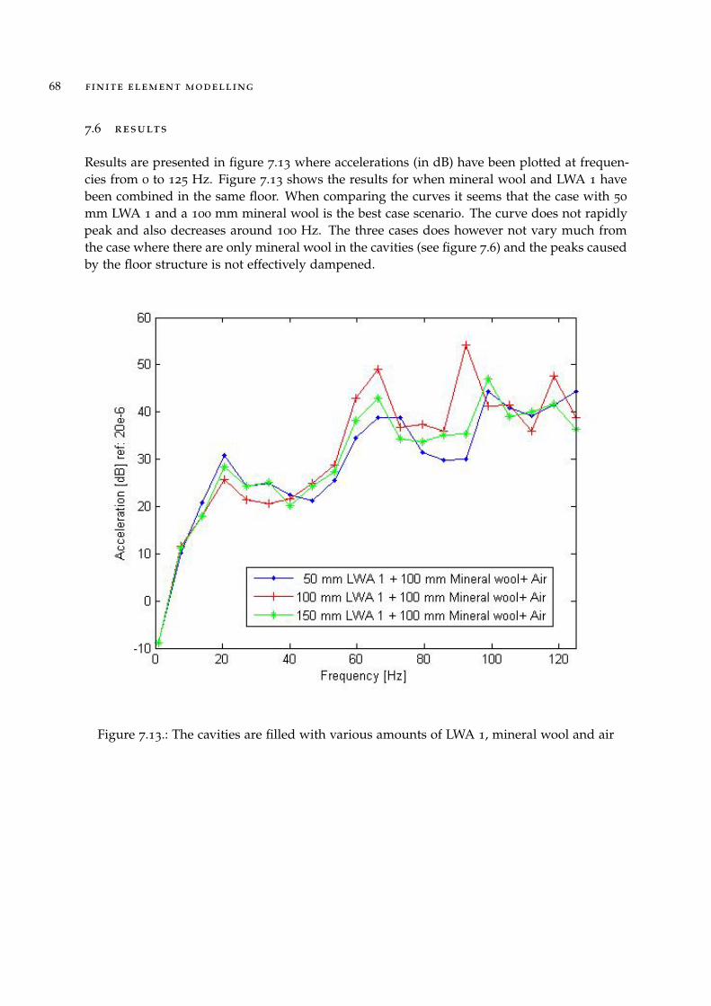
Results are presented in figure 7.13 where accelerations (in dB) have been plotted at frequen-cies from 0 to 125 Hz. Figure 7.13 shows the results for when mineral wool and LWA 1 havebeen combined in the same floor. When comparing the curves it seems that the case with 50
mm LWA 1 and a 100 mm mineral wool is the best case scenario. The curve does not rapidlypeak and also decreases around 100 Hz. The three cases does however not vary much fromthe case where there are only mineral wool in the cavities (see figure 7.6) and the peaks causedby the floor structure is not effectively dampened.
Figure 7.13.: The cavities are filled with various amounts of LWA 1, mineral wool and air

7.6 results 69
In the two following plots the results are presented in sound pressure level (Lp) at somemodes in the lower frequency interval (0-125 Hz). This in order to be able to make somecomparisons with measurements from Akustikverkstan (measurement results can be viewedin figure 7.12). Figure 7.14 shows the results for the three layer combinations. In this figureone can see that the SPL is lower around 80 Hz for all curves. This corresponds to the resultsfrom the measurements from Akustikverkstan (figure 7.12).
Figure 7.14.: The sound pressure level calculated in some modes for the receiving room atAkustikverkstan

70 finite element modelling
To simplify comparison, the best calculated case for the LWA 1 is plotted together withthe case where the cavities are filled with only mineral wool (see figure 7.15). In this figureone can see an improvement in the frequency range from approximately 40 to 90 Hz. Atfrequencies around 100 Hz and up there is an equally large deterioration and the curve seemsto have an up-going trend here.
Figure 7.15.: The best case with LWA’s are plotted in the same figure as the case where thecavities are filled with mineral wool. This in order to be able to compare and seeat what frequencies one can see improvements and deteriorations

7.6 results 71
The alternation of the volumetric drag and density did not give any significant results asseen in figure 7.16 and 7.17.
Figure 7.16.: The material parameters have been altered in order to see if change in flow resis-tivity or porosity can affect the results

72 finite element modelling
Figure 7.17.: The material parameters have been altered in order to see if change in densitycan affect the results
7.7 conclusions from abaqus simulations
The validation of the Abaqus model shows that one does not have to plot all nodes to providereliable results. It also showed that there was no need for an air gap between the top plateand the material, the results where the same. With the measurements of the laboratory roomat Akustikverkstan, it was possible to recalculate the accelerations in the bottom plate of theAbaqus model into sound pressure levels. This made comparison possible and one couldsee a correlation between the measurements and the calculations. This further validated thatthe model is reliable. The alternation of the material parameters density, flow resistivity andporosity did not give any significant improvement or deterioration. This implies that if onewants to improve the material, the structure needs to be altered in its structure in other ways.

Part IV
C O N C L U S I O N


8D I S C U S S I O N
The different parts of the thesis are presented and discussed. Conclusions of the LWA’s acous-tical properties are presented and future work is proposed.
8.1 market survey
The market survey did not reveal what type of load bearing structure that is most commonlyused today, but it gave examples of how floor structures could possibly look like in existingbuildings. What can be said anyway is that the main economic advantage in timber framedbuilding is that the building process can be sped up when building volume elements. TheEconomic advantage is an indicator that this will be the most popular building techniquein the future, but if the uncertainties in acoustic performance are not solved, light weightbuildings may gain a bad reputation.
The floating floor is of importance for sound insulation properties. The technique reducespropagation of vibrations in the primary structure and dampen them out instead. Floatingfloors are in some extent used in all floor constructions that I have come across during themarket survey. When having beams as primary structure, elastomers that are special madefor sound insulation sometimes can be installed between the primary and secondary floorstructure. For the elastomers to be effective, they must be able to carry the load of the aboveelements.
One can see that even though wood is used as load bearing structure, it is common thatthere are layers of concrete somewhere in the floor structure. The concrete layer can interactwith the timber as load bearing structure, or be used as a leveler to put the actual floor coveron. Concrete also have a main acoustical advantage over timber: it is heavier and stiffer andthis results in less structure borne vibrations in concrete buildings compared to timber framedones. One main reason to build light weight timber structures is to avoid concrete as it is notvery eco-friendly 1. However, the concrete quantities are much less in these types of timberconstructions than if it would have been used as load bearing structure all together.
1 This is a well-discussed subject where on can argue that the concrete binds CO2 in the manufacturing process.However concrete demands large amounts of virgin materials that can not be recycled
75
76 discussion
The building materials that was discussed to be replaced by LWA 1 and 2 are concrete,ballast or mineral wool. The building material that bears the most similarities with the LWA’sare ballast and is therefore easiest to replace in an existing building solution. As the LWA’smaterial properties are very different from concrete or mineral wool, these materials cannotbe replaced without further investigation.
If discussing replacing mineral wool with the new LWA’s it is important to take into accountthat the LWA’s have a significantly higher density. In case of replacement from a lightermaterial, load bearing capacity calculations must be carried out considering the new, heaviermaterial. Another important aspect one always needs to consider when introducing a newmaterial in a building structure is how the material interacts with other materials in termsof moisture. This is of course of greatest importance for the building envelope but shouldbe verified for all building components. It also need to be determined that the material doesnot contain any toxic substances that could be a health risk for builders and residents. ForLWA 1 the issue of glass wool dust should also be considered for them who will handle thematerial. The joint between outer wall and floor often causes a thermal bridge in which casefloor insulation material with good thermal insulation properties can be preferable to reducethis effect.
The price range that was concluded from chapter 5 shows a quite wide range. Dependingon if the new materials improve the acoustical performance or not in comparison to otheracoustical materials, the price can be set higher or lower. Even with the assumption that thenew LWA’s can provide with equivalent sound reducing ability, it probably needs to be at thelower price range to be preferred over other proven materials. As the construction industryhave an unfortunate history of trying new building materials without properly testing themout first (for example asbestos or rhoca gil), there are a reluctance against trying new materialsif they are not properly tested. This sets a greater pressure on the manufacturer (in this caseEcophon) to prove the material to work, not only from an acoustical point of view.
From an environmental viewpoint there are always benefits in reusing residue as this re-duces the use of virgin materials in other productions. Today there are not that much focuson EPD’s in general in the building industry, but it is likely that this becomes more impor-tant in the future as the focus on the environment increases and rules and regulations getstricter. In the future it is likely that the EPD’s will play a great role when a builing companywill choose their material and therefor it can be of interest to optimize them to keep up withthe development of the markets future environmental interest. Recycling of waste can thenbe one of the most important ways to lower the GWP for Ecophons current products. Thegreen building certification systems that where discussed in chapter 5 demanded quite largeamounts of recycled material, the quantities being so large that the intermediate floors areinsignificant. This does not make it less important to use environmentally friendly materialsin the floors, but it can be more difficult to motivate a construction company to use a materialthat doesn’t give any visible results in the certification system.

8.2 calculations 77
8.2 calculations
Analyzing accelerations in the bottom plate for frequencies up to 125 Hz showed no signifi-cant improvement when adding LWA 1 into the floor. The accelerations where lowered forfrequencies around 40-90 Hz but then again got worse around 100 Hz. To motivate an im-provement, the accelerations would have to be lowered for all calculated frequencies. Evenif the accelerations in the plate for some frequencies decreases more with LWA 1 added, it isnot more than a couple of dB which cannot be considered as a significant improvement. Themost likely reason for the LWA’s acoustic performance is its lack of stiffness which otherwiseis the main reason to add mass. In this case the mass is added without providing the neces-sary amount of stiffness. The goal of adding stiffness to a light weight construction is to gofrom the few-mode-range (where the spring stiffness dominates the insulation properties) tothe multi-mode-range (where the mass dominates the insulation properties). This is not fullyachieved with the LWA.
At frequencies over 20 dB the LWA’s show an irregular behaviour where some frequenciesare effecively dampened out but some are not. This is an effect of the granular structure thatmakes the material transmissive. Overall, the mineral wool shows a more predictable curvewhere there are no sudden peaks at either high or low frequencies.
Finally, it should be mentioned that this thesis is focused on a frequency interval that ba-sically is out of boundaries for the Swedish and European standard today. This makes theanalysis of the material quite demanding. Dampening out frequency levels bellow 50 Hz stillremains a discussion and proper calculation- and measuring methods must be found in orderto be able to apply it to ISO-standards.
8.3 proposal of future work
For future work, an investigation of other possible applications for the LWA’s might be ap-proached. Maybe investigate if one could replace concrete or ballast rather than mineral wool,and find out if the stiffness of the material could be improved. Maby the main structure ofthe material could be changed. It is also of greatest interest to investigate other possible appli-cations for the material. Could it be used in some other area of the building industry, maybefor foundation? If the material will be used as a building material in some extent, it needs tobe studied not only from an acoustical approach but all its properties need to be investigated(for example toxic substances and moisture resistance).
Possible applications for the material should be investigated further as the manufacturingprocess is cheap and energy efficient in comparison to other recycling methods for mineralwool residue. This is of interest for Ecophon, not only from an environmental point of viewbut also from an economical perspective.


B I B L I O G R A P H Y
[1] Rikard Öqvist. Variations in sound insulation in lightweight timber constructions. Luleå:Luleå University of Technology, 2010.
[2] The architects journal. New innovation from Ecophon. 2011. url: http : / / www .architectsjournal . co . uk / home / new - innovation - from - ecophon / 8613144 .fullarticle (visited on 04/08/2016).
[3] Erling Nilsson et al. Grundläggande Akustik. Lund: Department of constructions sciences,2008.
[4] Lakeside audiology. About your hearing health. url: http://www.lakesideaudiology.com/hearing_health.php (visited on 01/26/2016).
[5] WHO. Guidelines for community noise. 1999.
[6] TutorVista. Wave Frequency. url: http : / / physics . tutorvista . com / waves / wave -frequency.html (visited on 06/31/2016).
[7] Dakota Ultrasonics. References. url: http://www.dakotaultrasonics.com/reference/(visited on 02/02/2016).
[8] Juan Negreira. Vibroacoustic performance of wooden buildings - Prediction and perception.PhD Thesis TVBA-1013. Lund: Department of Construction Sciences, Division of Engi-neering Acoustics, 2016.
[9] O flodén and J Negreira and K Persson and G Sandberg. The effects of modelling acousticmedia in cavities of lightweight buildings on the transmission of structural vibrations. Depart-ment of construction sciences, 2014.
[10] ISO. Acoustics - Rating of sound insulation in buildings and of building elements- Part 2: Impactsound insulation. International Organization for Standardization, 1996.
[11] Tor Erik Vigran. Building Acoustics. USA: Taylor Francis, 2008.
[12] New England Soundproofing. The facts about impact noise. url: http : / / www .newenglandsoundproofing . com / facts _ about _ impact _ noise . html (visited on05/31/2016).
[13] Marc Asselineau. Building Acoustics. USA: Taylor Francis Group, 2015.
[14] Per Gunnar Burström. Byggnadsmaterial -Uppbyggnad, tillverkning och egenskaper. Dan-mark: Studentlitteratur, 2007.
[15] Igor Aranson and Lev Tsmiring. Granular Patterns. Oxford: Oxford Shcolarship Online,2008.
79
80 Bibliography
[16] Klas Hagberg and Delphine Bard. “Sound insulations descriptors in Europe- specialrules complicate harmonization within lightweight industry”. In: Building Acoustics(2010), pp. 277–290.
[17] BBR. Regelsamling för byggande, BBR. Boverket, 2015.
[18] Emma Arvidsson (2016-02-03). Frågor om de nya granulaten (F.Sandberg, Interviewer).
[19] Yifu Gou. Characterization of Vibro-acoustical Properties of Granular Beds. Master Thesis.Saint- Gobain Recherche, 2015.
[20] Thomas Ekenberg. Stort marknadsintresse att bygga i trä. 2013. url: http : / / www .skogsindustrierna.org/skog-industri/innehall/skog_och_industri_nyhetsarkiv/nyheter_4/stort-marknadsintresse-att-bygga-i-tra (visited on 03/14/2016).
[21] Träguiden. Generell beskrivning av massivträteknik. url: http : / / www . traguiden .se / planering / planera - ett - trabygge / byggsystem / massivtrateknik / generell -beskrivning-av-massivtrateknik/ (visited on 02/19/2016).
[22] Brettstapel construction. Brettstapel. url: http://www.brettstapel.org/Brettstapel/Home.html (visited on 03/11/2016).
[23] Klas Hagberg. Sammanställning av typiska konstruktioner inom Europa av trä och betong.WSP, 2015.
[24] Träduiden. bjälklag. url: http : / / www . traguiden . se / konstruktion /konstruktionsexempel/bjalklag/ (visited on 04/08/2016).
[25] Greenspec. Crosslam timber / CLT - Intermediate floor construction. url: http : / / www .greenspec.co.uk/building-design/crosslam-timber-intermediate-floors/ (vis-ited on 04/08/2016).
[26] Lignatur. Home. url: http://www.lignatur.ch/en/home/ (visited on 02/17/2016).
[27] Lignatur. Workbook. url: http://www.lignatur.ch/fileadmin/ablage/downloads/workbook _ a4 _ en / 2014 - 06 - 04 _ workbook _ a4 _ en _ schallschutz . pdf (visited on04/08/2016).
[28] Roberto Crocetti et al. Design of Timber Structures. Malmö: Swedish Wood, 2011.
[29] Kevin Dunne. Stegljudsmätning vid Ånässkolan. Lokalförvaltningen, 2014.
[30] Träguiden. Casa Nova i Danmark. 2003. url: http://www.traguiden.se/konstruktion/konstruktionsexempel/ljudisolering/ljudisolering/casa-nova-i-danmark1/ (vis-ited on 04/08/2016).
[31] Optimera Lund (2016-03-07). Materialförsäljning (F. Sandberg Interviewer).
[32] Marcus Dehlin (2016-03-07). Materialförsäljning (F. Sandberg Interviewer).
[33] Wikells Byggberäkningar AB. Sektionsfakta - NYB 12/13. Växjö: Elanders, 2012.
[34] Anna Palminger (2016-03-21). Miljödisskussion (F. Sandberg Interviewer).

Bibliography 81
[35] European Comission. Directive 2008/98/EC on waste (Waste Framework Directive). url:http://ec.europa.eu/environment/waste/framework/ (visited on 03/21/2016).
[36] Sweden Green Building Council. BREEAM. Sundbyberg, 2013.
[37] USGBC. Recycled content. 2009. url: http://www.usgbc.org/credits/commercial-interiors-retail-ci/v2009/mrc4 (visited on 04/18/2016).
[38] Niels Ottosen and Hans Pettersson. Design of Timber Structures. Edinburgh: Prentice HallEurope, 1992.
[39] Acoustics. Material Properties. url: http : / / www . akustik . lth . se / fileadmin /tekniskakustik/education/VTAF05/MaterialProperties.pdf (visited on 05/04/2016).
[40] Kristian Berbom Dahl. Mechanical properties of clear wood from Norway spruce. Norway:Faculty of Engineering Science and Technology, Department of Structural Engineering,2009.
[41] Abaqus analysis user’s manual. Acoustic medium. url: http://web.byggmek.lth.se:2080/v6.11/books/usb/default.htm?startat=pt05ch25s03abm57.html#usb-mat-cacousticmed-define (visited on 05/04/2016).
[42] Jean-Francois Allard and Philippe Herzog and Denis Lafarge and Masayuki Tamura. Re-cent topics concerning the acoustics of fibrous and porous materials. Laboratoire d’AcoustiqueAssocié au CNRS, 1991.
[43] Pontus Thorsson. Laboratory measurments for floor constructions for Saint-Gobain EcophonAB according to SS-EN ISO 10140-2:2010 and 10140-3:2010. Tech. rep. 2016.


L I S T O F F I G U R E S
Figure 1.1 to the left: LWA 1 and to the right: LWA 2 [2] 12
Figure 2.1 The ear[4] 15
Figure 2.2 Correspondence between sound pressure level (SPL) and sound pres-sure (SP) 16
Figure 2.3 Frequencies and amplitudes contra the perception of sound. Inspira-tion from [6] 17
Figure 2.4 Frequencies can be divided in bands. This piano shows an oc-tave. 18
Figure 2.5 Principle sketch of the sound reduction/frequency dependence for asingle wall [3]. The few-mode range is typical for light weight con-structions and the multi-mode range is typical for heavy construc-tions. 19
Figure 2.6 The sound reduction for a double wall with and without insulation inthe cavities. As a reference, a single wall with the same weight as thedouble wall is also plotted [3]. 20
Figure 2.7 Flanking transmission. Inspired by [3] 21
Figure 2.8 Parts of the sound wave energy is converted into heat. The rest trans-mitts through the material. 23
Figure 2.9 Visualisation of impact noise [12]. 24
Figure 2.10 Difference between a laboratory case (left) and a field case (right)[11]. 25
Figure 2.11 The difference between "grain" and "granular". 26
Figure 3.1 LWA 1 used at a landfill in Landskrona 30
Figure 3.2 LWA 2 manufactured in laboratory 31
Figure 4.1 General sketch of a CLT element [25]. The slab is covered with a layerof concrete with impact sound insulation layer on top. 36
Figure 4.2 2D model of a casette structure with inspiration from [24] 37
Figure 4.3 Example of box element floor slab with inspiration from [27]. Thisbox element is filled with ballast and there are three material layers(honeycomb fill, sound impact insulation and screed) on top. 38
Figure 4.4 Example of a glulam floor [30]. Stratigraphy from the top: sand, soundimpact insulation board, particle board, glulam beams with mineralwool and two layers of gypsum. 39
Figure 4.5 The volume elements are prefabricated and assembled at the construc-tion site. In order to prevent sound transmission between elements, anelastomer is put between the elements. [1] 40
83

84 List of Figures
Figure 4.6 Example of assembly between volume elements creating a floor slab[1]. 41
Figure 6.1 EUs waste hierarchy [35] 49
Figure 7.1 The floors structure. 54
Figure 7.2 General explanation of the finite element method. 54
Figure 7.3 A sketch of the floor slab with measurements. 55
Figure 7.4 The frame modelled in Abaqus. The upper image shows the frameof beams and the lower image shows both beams and plates assemledcreating the enire frame. 58
Figure 7.5 The plate is partitioned, making assembling possible. 59
Figure 7.6 Three plots where the cavities in the Abaqus model is filled with air,mineral wool and LWA 1 respectively. 60
Figure 7.7 It is validated that the Abaqus model gives the same result for half ofthe plate as for one fourth of the plate. 61
Figure 7.8 Cavities in the floor are filled with mineral wool. The blue plot showsthe case where the mineral wool is tied to the top plate. The red plotshows the case where there is a 3mm air gap between the mineral wooland the top plate. 62
Figure 7.9 For validation, nodes from half the plate is chosen to find out if it givesthe same result as if one fourth of the nodes are chosen. 63
Figure 7.10 The simulation results are exported from Abaqus as accelerations andrecalculated to sound pressure levels with respect to the dimensions ofthe laboratory at Akustikverkstan. This gave comparable results. 64
Figure 7.11 Principle sketch showing the measurements of the recieving room ofthe laboratory at akustikverkstan 66
Figure 7.12 The measurments carried out by Akustikverkstan is done on for a CLT-floor covered with 80mm LWA 1, Isover TDPS 30 and 70mm screed[43] 67
Figure 7.13 The cavities are filled with various amounts of LWA 1, mineral wooland air 68
Figure 7.14 The sound pressure level calculated in some modes for the receivingroom at Akustikverkstan 69
Figure 7.15 The best case with LWA’s are plotted in the same figure as the casewhere the cavities are filled with mineral wool. This in order to be ableto compare and see at what frequencies one can see improvements anddeteriorations 70
Figure 7.16 The material parameters have been altered in order to see if change inflow resistivity or porosity can affect the results 71
Figure 7.17 The material parameters have been altered in order to see if change indensity can affect the results 72

L I S T O F TA B L E S
Table 2.1 Velocity of sound in steel and air [3] [7]. 18
Table 2.2 Sound classifications described in dB [9] 21
Table 2.3 Impact sound requirements in some European countries [16]. 27
Table 3.1 Summary of mechanical parameters for LWA 1 and LWA 2 30
Table 5.1 Price levels for an approximate layer size of 100 mm for mineral wool,concrete and gravel [33] 47
Table 5.2 Price levels for the materials mentioned in 5.2 after a 50 % dis-count 48
Table 7.1 Material parameters used for isotropic materials [39] 56
Table 7.2 Material parameters used for the glulam beams. Wood is consid-ered a orthotropic material [40]. ρ is given in kg/m3 and E and Gin MPa. 56
Table 7.3 Material parameters used for acoustical materials [42] 57
85


A C R O N Y M S
BBR Boverkets Byggregler
BREEAM BRE Environmental Assessment Method
cc Center Distance
CLT Cross Laminated Timber
EPD Environmental Product Declaration
FEM Finite Element Method
GWP Global Warming Potential
LEED Leadership in Energy and Environmental Design
LWA Light Weight Aggregate
PBL Plan- och Bygglagen
RMS Root Mean Square value
SPL Sound Pressure Level
SP Sound Pressure
WHO World Health Organization
87


Part V
A P P E N D I X


AA P P E N D I X A
Abbreviated Matlab code:
SCRIPT 1: calculating RMS values of accelerationsclear allclose allAair = [1. 0. 6.26316 0. ... ... 95.7368 35.0665E-03 101. 650.508E-03];plockar ut alla accelerationer från matrisen ANOAIR aAcc = Aair(:,2);skapar en vektor med de plateser jag vill hämta ut från aAcc steps = zeros(104,1); n =
length(steps);————————–step 1———————————for i=0:103 steps(i+1)=(20*i+1); endstepsb1 = 0;for j = 1:length(steps) b1= b1 + (aAcc(steps(j)))2; enda1 = sqrt((1/n)*b1)repeat for-loops for all steps———————-Plottar Acceleration för air—————-ploty = [a1 a2 a3 a4 a5 a6 a7 a8 a9 a10 a11 a12 a13 a14 a15 a16 a17 a18 a19 a20]plotx = [1. 6.26316 11.5263 16.7895 22.0526 27.3158 32.5789 37.8421 43.1053 48.3684 53.6316
58.8947 64.1579 69.4211 74.6842 79.9474 85.2105 90.4737 95.7368 100];———–export acceleration matrix to plot-script———————
SCRIPT 2: plot accelerations————-matriser med accelerationen uttryckt i decibel————
air = [2.64717810289984e-06 ... 0.0367994185024515 2.20246271491814]; MU =[2.59428041695602e-06 ... 0.0351238624620481 0.220736064176765]; EcoDrain =[2.62102761352813e-06 ... 0.164379650574898 0.199554458456087];
are f = 20e− 6;airplot = 10*log10(air/are f ); MUplot = 10 ∗ log10(MU/are f ); EcoDrainplot = 10 ∗
log10(EcoDrain/are f );frekplot = [1. 6.26316 11.5263 ... 95.7368 100];
91

92 appendix a
figure(1) plot(frekplot, airplot, ’-’) hold on plot(frekplot, MUplot, ’- r’) hold on plot(frekplot,EcoDrainplot, ’- g’)
xlabel(’Frequency [Hz]’) ylabel(’Acceleration [dB] ref: 20e-6’) title(”)