Embed Size (px)
Citation preview
Report
Investigation of gas blowout on Snorre A, Well 34/7-P31A, 28 November 2004
2
REPORT TITLE
CLASSIFICATION
Gransking av gassutblåsning på Snorre A, brønn 34/7-P31 A 28.11.2004
Public þ Exempt from public disclosure o Restricted o Proprietary o Very confidential o REPORT NUMBER
WRITER/EXECUTIVE OFFICER
Marit Brattbakk (Investigation Leader), Lorents-Øystein Østvold, Claas van der Zwaag, Hallvard Hiim ORGANIZATION UNIT APPROVED BY / DATE
T1-StatoilGassco
SUMMARY
During work in well P-31A on Snorre A on 28 November 2004, a gas blowout occurred on the seabed with subsequent gas on and under the facility. Many of the personnel were evacuated by helicopter to nearby facilities. The emergency response team on board considered full evacuation on three separate occasions. The flare continued to burn during parts of the incident and was a potential ignition source for gas from the sea. The flow of gas was halted and the well was stabilized at 10:22 hours on 29 November 2004. On 29 November 2004, the PSA appointed an investigation group which has identified non-conformities and improvement areas. These can be categorized as follows: Lack of compliance with governing documents, inadequate understanding and implementation of risk assessments, inadequate management involvement and violation of well barrier requirements. The non-conformities occurred at several levels in the organization on land and on the facility. The investigation shows that the number of non-conformities and improvement areas is extensive. There is nothing that would indicate that the incident was a result of chance circumstances. The PSA characterizes this incident as one of the most serious to occur on the Norwegian shelf. This is based on the potential of the incident. NORWEGIAN TOPIC WORDS
Gas blowout, non-conformity, Snorre A, slot recovery, well control, well integrity, MTO
PROJECT NUMBER NO. OF PAGES NO. PRINTED
12J18 51 1
PROJECT TITLE
Investigation of gas blowout on Snorre A, Well 34/7-P31A, 28 November 2004
3
SUMMARY On 28 November 2004, an uncontrolled situation occurred during work in Well P-31A on the Snorre A facility (SNA). The work consisted of pulling pipes out of the well in preparation for drilling a sidetrack. During the course of the day, the situation developed into an uncontrolled gas blowout on the seabed, resulting in gas on and under the facility. Personnel who were not involved in work to remedy the situation were evacuated by helicopter to nearby facilities. The work to regain control over the well was complicated by the gas under the facility which, among other things, prevented supply vessels from approaching the facility to unload additional drilling mud. After having mixed mud from the available well fluid chemicals, this was pumped into the well on 29 November 2004, and the well was stabilized. With the well stabilized and the gas flow stopped, the work to secure the well with the necessary barriers could commence. The PSA characterizes this incident as one of the most serious to occur on the Norwegian shelf. This is because of the potential of the incident, as well as comprehensive failure of the barriers in planning, implementation and follow-up of the work on well P-31A. Only chance and fortunate circumstances prevented a major accident with the danger of loss of many lives, damage to the environment and additional loss of material assets. The consequences of the incident are costs related to delayed production, comprehensive and time-consuming work to secure the well, normalization and start-up of the facility. Surveys of the seabed after the incident revealed several large craters near the well template and near one of the fastening anchors for the Snorre A platform. Three months after the incident, production of oil and injection of gas/water had still not returned to normal levels. There were no physical injuries in connection with the incident. SNA is an integrated living quarters, drilling and production facility permanently anchored to the seabed with tension legs. Under the SNA is a well template with 42 wells with risers and several export lines. Total oil production from SNA is approx. 200,000 bbls/day. Under slightly different circumstances, the incident could have resulted in (1) ignition of the gas and (2) buoyancy and stability problems, with resulting danger of the loss of many lives, damage to the environment and additional loss of material assets. On 29 November 2004, the PSA appointed an investigation group to chart the course of the incident, identify potential breaches of the regulations, as well as propose use of policy instruments and recommendations for additional follow-up. The mandate included circumstances up to when the well pressures in P-31A were stabilized at 10:22 a.m. on 29 November 2004. A task force was also designated to monitor the normalization work. The investigation group has interviewed relevant personnel from the land organization and on the facility, evaluated the submitted documents and conducted an inspection on the facility. An MTO (man-technology-organization) diagram to map direct and underlying causes was prepared to assist in analyzing the incident. The regulations require technical, operational and organizational barriers that both prevent serious incidents from occurring and that they escalate. Serious failures and deficiencies have been uncovered in all phases of Statoil's planning and implementation on well P-31A. These relate to:
4
• Failure to comply with governing documentation • Deficient understanding and implementation of risk assessments • Deficient involvement of management • Breach of well barrier requirements. The non-conformities relate to failure on the part of both individuals and groups in Statoil and with the drilling contractor. The non-conformities occurred at several levels in the organization on land and on the facility. The investigation shows that the list of non-conformities and items that could be improved is extensive. Therefore, there is nothing to indicate that the incident was caused by chance circumstances. The non-conformities found in the investigation would all have been intercepted and corrected if the barriers had functioned. Individual barriers fail from time to time, but failure of so many barriers in different phases of an operation is extremely rare. The PSA is critical of the fact that such an extensive failure of the established systems was not uncovered. We question why this was not discovered and corrected at an earlier point in time.
5
TABLE OF CONTENTS 1 INTRODUCTION ...............................................................................................................................................7
1.1 THE PSA'S FOLLOW-UP OF THE INCIDENT ....................................................................................................7 1.2 MANDATE FOR THE PSA'S INVESTIGATION GROUP......................................................................................7 1.3 LIMITATIONS..................................................................................................................................................8 1.4 METHODS.......................................................................................................................................................8 1.5 INTERVIEWS, VERIFICATION ON THE FACILITY AND EVALUATION OF DOCUMENTS....................................8
2 STATUS PRIOR TO THE INCIDENT ...........................................................................................................9 2.1 HISTORY / DESCRIPTION SNA.......................................................................................................................9 2.2 HSE BEFORE OPERATIONS START-UP ...........................................................................................................9 2.3 WELL HISTORY AND STATUS OF P-31A PRIOR TO THE INCIDENT ................................................................9
3 COURSE OF EVENTS.....................................................................................................................................11 3.1 FIRST PART: PLANNING OF THE OPERATION ...............................................................................................12 3.2 SECOND PART: COMPLETION PHASE OF PLANNING AND START-UP OF WELL OPERATION ........................14 3.3 THIRD PART: THE WELL CONTROL SITUATION DEVELOPS..........................................................................17
4 POTENTIAL OF THE INCIDENT................................................................................................................23 4.1 ACTUAL CONSEQUENCES ............................................................................................................................23 4.2 POTENTIAL CONSEQUENCES........................................................................................................................24
5 OBSERVATIONS..............................................................................................................................................24 5.1 OBSERVED NON-CONFORMITIES .................................................................................................................26
5.1.1 Non-conformity 1. Applied method in internal audit has not revealed deficient compliance with governing documents...........................................................................................................................................26 5.1.2 Non-conformity 2. Milestones in the planning have not been implemented in accordance with governing documents...........................................................................................................................................26 5.1.3 Non-conformity 3. Planning with deficient well barriers in connection with perforation of the tail pipe 27 5.1.4 Non-conformity 4. The consequence of changes in the planning not sufficiently analyzed..............27 5.1.5 Non-conformity 5. Inadequate transfer of experience in connection with well integrity.................28 5.1.6 Non-conformity 6. Planning with changed well barrier when cutting scab-liner............................28 5.1.7 Non-conformity 7. Risk assessment in connection with planning and pulling of scab-liner............28 5.1.8 Non-conformity 8. Planning and pulling through the BOP ...............................................................28 5.1.9 Non-conformity 9. Inadequate management involvement in connection with assigning priority to the peer assist review...........................................................................................................................................29 5.1.10 Non-conformity 10. Inadequate approval procedures...................................................................29 5.1.11 Non-conformity 11. Signature page does not conform to governing document...........................30 5.1.12 Non-conformity 12. During planning, the meeting for review of overall risk is cancelled.........30 5.1.13 Non-conformity 13. Lack of transfer of experience after previous incidents...............................30 5.1.14 Non-conformity 14. Implementation of tail pipe perforation ........................................................31 5.1.15 Non-conformity 15. Executing link does not stop the operation before perforation of the tail pipe 31 5.1.16 Non-conformity 16. Inadequate handling of non-conformities .....................................................31 5.1.17 Non-conformity 17. Unclear procedure for drilling and completion operations.........................32 5.1.18 Non-conformity 18. Inadequate approval of HAZOPs ..................................................................32 5.1.19 Non-conformity 19. HAZOPs have not been communicated to the executing link ......................33 5.1.20 Non-conformity 20. Professional expertise does not assess overall risk......................................33 5.1.21 Non-conformity 21. Risk contributors are removed from the detailed program..........................33 5.1.22 Non-conformity 22. Scab-liner is perforated, cut and pulled........................................................34 5.1.23 Non-conformity 23. Lack of preparation for a well control situation...........................................34 5.1.24 Non-conformity 24. Inadequate well barriers when pulling scab-liner through BOP................35 5.1.25 Non-conformity 25. Inadequate risk assessments in connection with swabbing..........................35 5.1.26 Non-conformity 26. Kelly cock was blocked...................................................................................36 5.1.27 Non-conformity 27. Late confirmation of personnel overview......................................................36 5.1.28 Non-conformity 28. Inadequate logging .........................................................................................36
6
5.2 ITEMS FOR IMPROVEMENT...........................................................................................................................37 5.2.1 Classification of incidents .....................................................................................................................37 5.2.2 Communication ......................................................................................................................................37 5.2.3 Smoke detection in ROV container .......................................................................................................37 5.2.4 Exposure of personnel ...........................................................................................................................37 5.2.5 Registration system for POB.................................................................................................................38 5.2.6 Problems starting lifeboats....................................................................................................................38 5.2.7 Position descriptions, requirements......................................................................................................38
5.3 BARRIERS THAT FUNCTIONED .....................................................................................................................39 6 ASSESSMENT AND DISCUSSION OF UNCERTAINTIES ....................................................................39
6.1 DRILLING CONTRACTOR'S PARTICIPATION IN THE PLANNING....................................................................40 6.2 ORGANIZATIONAL CHANGES THAT ARE OF SIGNIFICANCE FOR THE INCIDENT .........................................40 6.3 PARTICIPATION IN MEETINGS ......................................................................................................................41 6.4 BREAKTHROUGH POINT FOR THE BLOWOUT...............................................................................................41 6.5 DISCHARGES TO THE EXTERNAL ENVIRONMENT / GAS VOLUME ...............................................................41
7 OTHER SIGNIFICANT FACTORS DURING THE INCIDENT ............................................................41 7.1 AIR INTAKE FOR CEMENTING PUMP ............................................................................................................41 7.2 GAS IN FIRE WATER .....................................................................................................................................42 7.3 SPREAD OF GAS............................................................................................................................................44 7.4 EFFECT OF REDUCED POWER SUPPLY..........................................................................................................45 7.5 FLARING AND DEPRESSURIZATION .............................................................................................................45 7.6 DANGER OF LOSS OF STABILITY AND BUOYANCY ......................................................................................46
7.6.1 Loss of tension leg through uplift of the foundations...........................................................................46 7.6.2 Loss of buoyancy of the hull in connection with upward flow of gas.................................................48
8 OTHER STUDIES.............................................................................................................................................48 8.1 NEED FOR ADDITIONAL STUDIES.................................................................................................................48
9 ABBREVIATIONS............................................................................................................................................48
10 APPENDICES................................................................................................................................................49
7
1 INTRODUCTION
In connection with a well workover and pulling a scab-liner, a well control situation arose in well 34/7 P-31A on the Snorre A (SNA) facility on 28 November 2004. This developed into a gas blowout on the seabed. Gas from the reservoir flowed to the surface. Crew members on SNA who were not involved in emergency response tasks or who were not directly involved in further well control work were evacuated to nearby facilities. This report sums up the results of the Petroleum Safety Authority Norway's (PSA's) investigation and presents these results on the basis of the investigation group's mandate.
1.1 The PSA's follow-up of the incident The PSA was notified by Statoil at 19:23 hours on 28 November 2004. The emergency response organization was mobilized at about 21:30 hours to monitor Statoil's work to ensure the safety of personnel and handling of the well problems. On Monday, 29 November 2004, the PSA decided to initiate its own investigation of the incident. The investigation group that was put together included the following persons from PSA's main group T-1-StatoilGassco, which follows up activities on the continental shelf where Statoil is the operator: Marit A. Brattbakk Head of investigation, Discipline Group Logistics and Emergency Preparedness Lorents-Øystein Østvold Discipline Group Drilling and Well Technology Claas van der Zwaag Discipline Group Drilling and Well Technology Hallvard Hiim Discipline Group Process Integrity Statoil and Odfjell Drilling have done a good job of facilitating the investigation.
1.2 Mandate for the PSA's investigation group The investigation group received the following mandate:
1. Chart the course of events 2. Identify triggering and underlying causes, with focus on man, technology and
organization (MTO) 3. Chart and evaluate emergency preparedness aspects, including responsibility, lines of
communication and available emergency response resources a. to/from the facility, 2nd line Sandsli and B&B Statoil Forus b. manning/mustering c. manning/evacuation d. helicopter, supply vessel, standby vessel
4. Evaluate the potential of the incident, including evaluation of potential ”worst case” scenarios, such as:
a. Gas exposure (below sea level) => affect on buoyancy, anchoring/tension legs, subsea facilities
8
b. Gas exposure (on the facility) => ignition sources (intervention in power supply/NAS2 (ESD2), operation of equipment on drill floor and hot surfaces, helicopter), escalation
c. Gas exposure (on the facility) => effect on personnel of exposure to hydrocarbons
5. Identify breaches of the regulations, recommend further follow-up and identify potential need for the use of policy instruments
6. Evaluate the need for resources and identify need for assistance, own studies and use of consultants.
1.3 Limitations The investigation includes charting of direct and underlying causes of the incident up to 10:22 hours on 29 November 2004. At that time the well was under control, i.e. the pressure below the BOP on the well was zero bar. A separate group has been designated in the PSA to monitor normalization after the incident, Statoil's measures in connection with start-up of production, as well as measures that must be implemented before drilling and well operations can be resumed.
1.4 Methods An MTO (man, technology and organization) diagram has been prepared to map the underlying and direct causes. 1
1.5 Interviews, verification on the facility and evaluation of documents In connection with the investigation, interviews have been conducted with involved personnel in the land organization, as well as personnel who were on the facility when the incident occurred. Because the well situation was uncertain in regards to the status of well barriers for a long time after the incident, and because personnel had been sent to land, the interviews were conducted in Stavanger. Relevant documents were also obtained from the facility and from the land organization. During the period 9-11 January 2005, the investigation group conducted a verification on SNA. At that point in time, the manning was the same as when the incident occurred. An inspection was carried out which included the control room, emergency response room, the drill floor, the Vigdis module, the cementing unit, the drilling mud unit, the UPS room, lifeboats, ROV container and areas where gas was detected during the incident. An overview of documents used in connection with the investigation is included in Appendix 2. Appendix 3 is a list of participants in the interviews conducted by the PSA. 1 See Appendix 1.
9
2 STATUS PRIOR TO THE INCIDENT
2.1 History / description SNA Saga Petroleum ASA was the original operator of SNA. Norsk Hydro AS took over the operator responsibility on 1 January 2000, until Statoil took over as operator on 1 January 2003. SNA is an integrated living quarters, drilling and production facility which commenced operations in 1992. The facility is anchored to the seabed with tension legs. Two subsea production facilities (UPAs) are tied in to the installation. Snorre UPA is situated on the seabed 6 km north-east of the facility, and Vigdis UPA is situated on the seabed 7 km south-west of the facility. The water depth in the area is 300-350 meters.
2.2 HSE before operations start-up The level of activity on SNA has been high for several years. When the incident took place, both drilling and well intervention were underway, as well as rigging of a new well intervention derrick. At the end of October/beginning of November, SNA changed drilling contractors from Prosafe to Odfjell Drilling. Odfjell took over about 80 % of Prosafe's SNA personnel. Nevertheless, there were several persons in Odfjell's drilling crew who were new to SNA when the incident occurred. In addition, Statoil's drilling supervisor was on his first trip to the SNA. Since September 2003, notification has been given of four serious incidents on SNA (Statoil's internal category "red"), of which two were well incidents and two were other types of incidents (falling object, serious personal injury). In the Snorre organization, there is a general perception that SNA is among the Statoil facilities with the worst HSE ranking/statistics.2 Experience gained from the investigation group's inspections indicate that the working environment on the facility is good.
2.3 Well history and status of P-31A prior to the incident Well P-31 was drilled as an observation well in 1994. The intention was to collect geological data to optimize the well path for the horizontal section of the well. The sidetrack P-31A was drilled and completed in the first half of 1995. The well was originally planned as a production well, but in early 1996 it was converted into an injection well for alternating water and gas injection (WAG). However, the well was chiefly used as a gas injector until it was shut in in December 2003. The following circumstances sum up the problems associated with drilling and completing the well:
- During drilling of Well P-31 in 1994, problems arose in connection with running the 13 3/8” casing in the 16” well section. The casing had to be cut and a new well patch
2 Ref. Statoil's target agreement (MIS).
10
sidetracked before the observation well was complete. The 30" conductor casing, 18 5/8" casing and the above-mentioned 13 3/8” casing from the operation in 1994 are the same as are used in the new well P-31A.
- During cementing of the 5 ½” extension pipe in the P-31A sidetrack in 1995, the drill
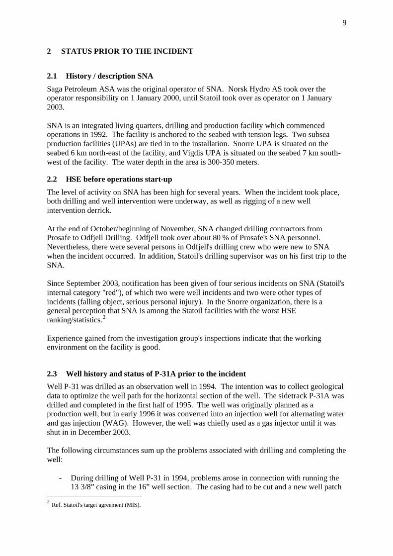
string got stuck. This led to a prolonged fishing and milling operation which in turn resulted in extensive casing wear in the 9 5/8” casing. After subsequent clean-up, logging/pressure testing showed that 2-3 holes had been flushed with high pressure washing tools at 1561 mMD (meters measured depth) (see Figure 1). 3
- A scab-liner with unconventional diameter (7 5/8”) and a length of 2578 m was installed to plug the holes in the 9 5/8” casing, as well as to reinforce the integrity of large parts of the pipe. The well was then pressure-tested to 255 bar. This was a downgrading of the pressure specification for this well section from the original 345 bar. After the pressure test, the well was completed with 5 ½” tubing. The well was started up in May 1995.
- In connection with a well campaign4, under the direction of Norsk Hydro, in June
2001, extensive corrosion was measured in the production tubing. In addition, leakage was noted between the tubing and the annulus. Therefore, to reinforce the integrity, a new scab liner, a 4” ”straddle”, was set in the lowermost section of the tubing.
Figure 1. USIT/CBL log from 1995 showing damage to the 9 5/8” casing In December 2003, leakage was once again observed between the tubing and the annulus. Subsequent pressure testing led to "casing burst" of the 9 5/8” casing. This was ascertained after the pressure went to 194 bar and then fell to 94 bar. Statoil therefore decided to shut the well in. The leakage point and the seriousness of the leak has not been analyzed. During the 3 Ref. document list, Item 42. USIT/CBL log from 18 March 1995 Schlumberger MAXIS 500 Field log 4 The campaign was called the "Zero holes campaign"
11
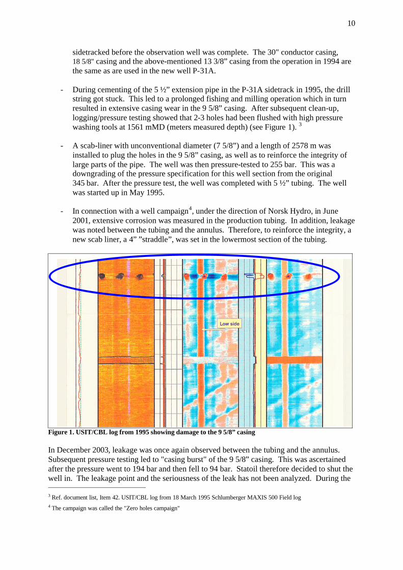
shut-in, well barriers were established, i.e. with a plug directly above the reservoir section, and the well was filled with brine.5 The well was considered to be "complex". This was related to (see Figure 2):
- Factors which give the well reduced integrity (corrosion, leaks). - Unconventional well completion with a great many small completion elements. - Additional completion elements installed in the well in connection with repairs (Scab-
liner and straddle) - Downhole well control valves
Figure 2. Well sketch reflecting status of well integrity prior to start-up of the well operation.
3 COURSE OF EVENTS
This chapter describes the actual course of events, based on information obtained in the investigation. The activities are described in chronological order. The description of assessments refers to the evaluations that were made by the personnel involved during the course of events. This chapter is divided into three main parts. The first part focuses primarily on the planning of the well operation, and relates to the time period from the spring of 2004 until start-up of SNA on 16 November 2004. The second part mainly deals with start-up of the well operation and up to when the well went out of control on 28 November 2004. The third part largely describes measures implemented to handle the situation when the well ran out of control. 5 CaCl2/CaBr2 brine with 1.47 s.g.

12
3.1 First part: Planning of the operation The well operation that was to be carried out on well P-31 A is called "slot recovery”. This is a preparatory operation to make ready for drilling a subsequent sidetrack, in this case P-31 B. It was ascertained that well P-31 A was damaged in December 2003 and the well was shut in. Exactly when the decision was made to start the planning work for slot recovery and the new sidetrack is unclear. The PSA was informed about the first planning phase in the spring of 2004. This is when the first draft of the ”Recommendation to drill” (RTD) was presented to the license. Statoil Snorre A subsurface group (SNA RESU) appointed a project team to plan slot recovery on P-31 A and drilling of the P-31 B sidetrack. The first formal planning meeting we are aware of was held on 17 June 2004. The program engineer who was assigned the task of planning the activity started to collect historical well data in July 2004. The summary of the well status emerged in a presentation given to SNA RESU. The presentation showed the many challenges related to well integrity in P-31A. 6 From September to mid-November 2004, several detailed planning meetings were held under the direction of the slot recovery project team. Several contractors participated in these meetings, e.g. for drilling mud, cementing, completion elements/plugs, cutting or perforation of existing pipes. The drilling contractor was not involved in these meetings. The original plan for slot recovery (September 2004) takes into account the deficiencies related to the integrity of the well. The reservoir section was not to be opened and cemented. An additional plug (cement) was to be set above the planned cut in the production tubing to provide a more robust solution. This emerges from a recommendation issued by Statoil's head office (Well Technology Support Function) on 31 August 2004. The recommendation entailed cementing or setting a mechanical plug above the so-called ”polished bore receptacle” (PBR) after pulling the 5 ½” tubing. A 2 7/8” HE3 plug was to function as a barrier element during pulling of the production tubing and scab-liner. During the course of October 2004, however, the original plan was changed. The reason for this is that the reservoir engineering group of SNA RESU, in the second detailed planning meeting on 1 October 2004, suggested that the reservoir section in well P 31A should be cemented using "squeeze cementing". The intent was to avoid communication with the subsequent sidetrack P-31B.7 However, the drilling and well engineering group of SNA RESU wanted to avoid cementing because this complicated the planning and execution of the slot recovery. At the end of October/beginning of November, Odfjell took over the drilling contract and, at the same time, about 80 % of Prosafe's SNA personnel. 6 Ref. document list item 13: “Snorre A-P-31 A, Pull completion & prepare for side-track, Statoil” and item 14: “Snorre A-P-
31 A Slot Recovery Operation – Schematics”. 7 Communication between two well bores can lead to an unpredictable flow pattern in the reservoir and insufficient oil
drainage.
13
In a preparatory meeting for RTD on 27 October 2004, the drilling and well engineering group acceded to the wishes of the reservoir engineering group. In the third detailed planning meeting on 2 November 2004, the original operations program was changed and adapted to this decision. Various methods were considered. Two of the alternatives were to pull the plug in the 2 7/8” tail pipe or to perforate the tail pipe above this plug. The assessment of technical experts from the supplier and the “slot recovery” project team in SNA RESU was that the method with the greatest chance of success was perforation. Therefore, they decided to perforate the tail pipe in order to pump cement past the HE3 plug and into the reservoir section. The original plan was to pull the 5 ½” tubing before perforating the tail pipe. After cutting and pulling the tubing, there would be a crossover from 9 •” to 5 ½”, which would lead to problems in connection with subsequent entry with perforation tools. Therefore, a decision was made to carry out perforation before the production tubing was cut and pulled. The wireline company wanted the tail pipe to be perforated in brine (a heavy salt water solution) before replacing this completion fluid with drilling mud. A better result was expected if the perforation was done in brine, and this wish was also accommodated. In the third planning meeting, the SNA RESU project team laid plans for:
• Perforation of the tail pipe, • Pulling the scab-liner in a single piece, and pulling this through the BOP.
In addition, potential problems with the perforations in the 9 5/8” casing, in relation to perforation of the tail pipe, were discussed, although none of these issues were identified as a risk or a breach of barriers. In addition to these planning meetings, several meetings were held with the suppliers of the equipment regarding the details of the plan. For example, meetings were held with Weatherford and Red Baron regarding cutting and pulling the 7 •” scab-liner, and with Baker regarding perforation of the 2 7/8” tail pipe. The fourth and final formal planning meeting was held on 11 November 2004. Both supplier personnel and personnel from SNA RESU participated in this meeting, which started with a review of the well's history before each individual sub-operation in the program was reviewed and discussed. A risk review (peer assist) for the entire program was planned for 12 November 2004. The risk review was postponed because of a collision of meeting times, with subsequent downgrading of priority on the part of the participants. The program was submitted to SNA RESU management for verification, recommendation and approval:
• Verified by the lead drilling engineer, 15 November 2004. • Verified by the lead well engineer, 16 November 2004. • Recommended by the drilling operations supervisor, 15 November 2004. • Approved by SNA RESU manager, 16 November 2004.

14
The following sub-operations had now been planned and approved in the slot recovery program.8
1. Perforation of the tail pipe. 2. Replacement of brine with oil-based mud. 3. Cutting and pulling the 5 ½” tubing. 4. Cutting and pulling the 7 5/8” scab-liner. (The incident occurred during this sub-
operation). 5. Cementing of the well's reservoir sections. 6. Cutting and pulling the 9 5/8” casing.
3.2 Second part: Completion phase of planning and start-up of well operation The operations in the neighboring well P-32 went more rapidly than planned, thus causing an earlier start-up for P-31A. The rig was skidded on 16 November 2004. On 16 November 2004, a departure meeting was held with the offshore drilling management for the day shift. At this informational meeting, the drilling program was presented with the aid of a Powerpoint presentation. The following Statoil personnel participated at this meeting: Drilling operations supervisor, program engineer, drilling supervisor - day shift. The following Odfjell personnel participated: Drilling operations manager, program engineer, drilling supervisor - day shift, while Odfjell Drilling was represented by: Drilling operations manager, toolpusher - night shift (toolpusher - day shift was not at the departure meeting because of flight problems), driller and assistant driller. On 19 November 2004, the planned risk review (peer assist) was cancelled. This is the same review that had been postponed from 12 November 2004. On the same date, the slot recovery operation commenced on SNA after installation of BOP and riser for drilling. Several problems occurred in the first phase of the operation, e.g. during cutting/perforation of the 5 ½” tubing (Item 3 in the program). Here, in the early morning hours of 21 November 2004, there was a flow of well fluid in the form of diesel and gas.9 The incident was subject to an internal investigation in Statoil. 21 November 2004: the drilling crew perforated the 2 7/8” tail pipe. This operation thus allowed for reservoir pressure/contact with hydrocarbon-bearing strata in the reservoir. The primary barrier now consisted of 1.47 s.g. brine. At 1930 hours on this same date, oil-based drilling mud was bullheaded with 1.47 s.g. and max. 100 bar pumping pressure into the well, and a new primary barrier was established. The brine was squeezed out of the well and into the near wellbore area to the reservoir section. On 23 November 2004, the drilling supervisor - day shift sent an e-mail to the program engineer with a copy to the drilling operations supervisor. The inquiry related to whether or not an application for exemption was required for pulling the 7 5/8” scab-liner without BOP- 8 Ref. document list Item 12 ”Snorre A Slot Recovery Program, 34/7-P-31 A, RA-Snorre-00219, November 2004” 9 Ref. document list Item 51. RUH 283229 ”Unintentional flow of gas/diesel”.
15
rams, i.e. the holding function in the BOP. The program engineer replied on the same day to the drilling supervisor: "As I understand it, we do not have to do this (application for exemption) as long as we pull a liner that is not out in an open hole.” On 24 November 2004 there was a meeting between the program engineer and the acting technical manager for cementing from the head office. His regular position is lead well engineer in TO RESU. The purpose of the meeting was, according to the invitation to the meeting, to discuss squeeze cementing of the reservoir section. The result of the meeting was that the plan was adjusted as regards the following item: A hole was to be punched in the top of scab-liner prior to cutting. The intention was to equalize for any potential gas and pressure behind the scab-liner. Only this part of the well barrier situation was considered in this meeting. A departure meeting was held for the night shift drilling management on the same day. the agenda was the same as for the day shift drilling management. Present in the meeting from Statoil: Drilling operations supervisor, program engineer, drilling supervisor - night shift. The drilling supervisor - night shift had not been on SNA since 1997, and the drilling contractor's toolpusher - night shift was on his first trip to SNA. Odfjell Drilling was represented by the operations manager, driller and assistant driller - night shift. On 23-24 November 2004, the 5 ½” tubing was cut and pulled. However, it was established that the tubing had only been partially cut, and that the lower part with the interior 4” straddle also followed the pulling operation. There was no equipment on board that would allow this to be pulled through the BOP, and the equipment was therefore requisitioned from land. Due to long lead time for the equipment, consideration was given to running the lower part of the 5 ½” tubing with the 4” straddle back into the well. In a meeting with a well technologist from the well control group at the head office (HQ) and the program engineer on 25 November 2004, the sub-operation "perforation and pulling of the 7 •” scab-liner" was discussed. Once again, only the sub-operation was discussed; and not the overall status of well barriers. During the period 23-25 November 2004, the operative detailed plan for Items 3 and 4 of the program were modified on board the facility:
Item 3: Cutting and pulling of 5 ½” tubing, is adapted to the operational problems that arose in connection with cutting the 5 ½” tubing. Detailed procedures for dropping the 5 ½” tubing with 4” straddle are drawn up. Item 4: Cutting pulling of the 7 5/8” scab-liner in the slot recovery program was split into two sub-items:
a. Perforation of scab-liner. b. Cutting and pulling of scab-liner.
The purpose of Item a) was to equalize any gas pressure behind the scab-liner.
16
The detailed plans were completed by the drilling supervisor and toolpusher on the 25th and 26th of November respectively. At the same time, risk assessments in connection with taking the scab-liner through the BOP were removed from the detailed plan.10 On 25 November 2004, the land organization conducted risk analyses (HAZOPs), for two sub-operations in the program. HAZOP No. 1: dealt with ”Drop of 5 ½” tubing with 4” straddle”. The document was approved and signed by the SNA RESU manager when it was completed. HAZOP No. 2: dealt with "Perforation and pulling of scab-liner”. The document was not signed/approved by the SNA RESU manager. On 25 November 2004, the tubing with straddle was unscrewed from the work string. The pipe sections were run into the well and dropped. The scab-liner was punctured on 27 November 2004. The crew waited for an hour and observed the well for gas. The liner hanger at the top of the scab-liner was then cut and pulled. The crew then started to pull the scab-liner itself out of the fastening point in the bottom (PBR). An expected ”U-tube” effect, due to the fact that the brine behind the scab-liner was heavier than the drilling mud, was not observed. According to the detailed program, this effect should have resulted in a pressure increase of 32 bar in the mud system. However, the anticipated pressure change was not recorded. During the pulling operation, the crew stopped at regular intervals and observed the well for volume changes. It later proved that the casing spear that fastened the drill string/work string to the scab-liner either had no seal, or the seal was defective. Therefore, observation of a "u-tube" effect was not possible. In the same evening, swabbing was noted for the first time11. In the first part of a pulling operation, swabbing is not regarded as abnormal. At this point in time, approx. 2 m3 of reservoir fluid12 was swabbed when pulling the 2nd and 3rd stand. 13 As compensatory measures for the observed swabbing, the drilling report describes that they "pull the scab-liner slowly and make regular observations”. On 28 November 2004 during the period from 0000 - 0215 hours, the drilling crew pulled a single, but swabbing continued. The drilling supervisor - night elected to stop and discuss the situation with the toolpusher and drilling supervisor - day. Another attempt was then made to circulate the well down through the scab-liner and up the annulus on the outside. Low circulation pressure and rapid return of drilling fluid to the surface was observed. This was 10 Ref. document list Items 38 and 55. E-mail correspondence between the program engineer and the drilling supervisor dated
23 November 2004. 11 Swabbing is an undesirable piston effect that can occur during pulling of pipe strings. 12 2 m3 gas under reservoir conditions is equivalent to about 20 m3 on the seabed and 200 m3 at atmospheric pressure. 13 One drill pipe / a ”single”= approx. 9 m . One stand = approx. 27 m = 3 drill pipes/”single”
17
another sign that the casing spear did not have the necessary seals, or that the seals were defective, i.e. the circulation went through the casing spear and not through the scab-liner. They observed that the well took mud, i.e. that the volume balance in the well seemed satisfactory and just as much mud went into the well as came out. During further pulling of the scab-liner they were repeated forced, for various reasons, to use overpull. This means that the traction used was greater than the weight of the scab-liner. At 0500 hours, the top of the scab-liner was under the BOP. Before the drilling crew pulled this through the BOP, they stopped and observed to check for changes in the well volume (flowcheck). The well did not exhibit any changes in volume. The scab-liner was pulled on through the BOP and blocked the cut and hold function. At 0700-0715 hours on 28 November 2004, the crew changed from night to day shift. During the period 0800 – 1530 hours, the day shift continued to pull the scab-liner. Swabbing with altogether approx. 4 m3 volume increase was observed, and mud loss equivalent to 31 m3 was also observed. During this period, the operation was observed for flowcheck for both brief and longer periods. Again, the well was regarded as being stable, and the drilling crew continued to pull the scab-liner after each flowcheck. During the course of the day, the drilling supervisor maintained continuous contact with the OIM and the drilling operations supervisor on duty on land, in order to inform them about developments in the well.
3.3 Third part: the well control situation develops At 1530 hours on the same day, the annular preventer of the BOP stack was closed, for the first time, due to influx. This type of valve was the only one of three types of safety valves that could be utilized in the BOP. A Kelly cock was installed and the top drive was screwed in. After a brief period of pressure increase, the well started to lose pressure. At about 1630 hours, the annular preventer was opened again, to pump mud to offset for the mud loss. A total of about 25 m3 of drilling mud was pumped into the work string and annulus. Attempts were made to circulate the well, but no mud was returned. Up until 1800 hours, the well was observed and an additional loss totaling 13 m3 was ascertained and noted in the drilling report. The increasing problems with well P-31A throughout the afternoon were the topic of discussion at the regular platform management meeting at 1700 hours. The planned emergency preparedness drill was cancelled because of the situation. At about 1800 hours, after an attempt was made to reverse-circulate the well (down the annulus and up the work string), a backflow of well liquids was observed, which developed in an undesirable manner. Once again, the annulus safety value was closed in the BOP. The instability in the well proved to be on the rise, with a strong pressure increase to approx. 130 bar in the course of 2 hours.
18
The drilling supervisor - night came on duty at 1830 hours, and the night shift started its shift around 1900 hours. In order to gain control over the well, at about 1900 hours SNA had available mud reserves of about 250 m3 oil-based mud (OBM). The drilling crew was in the process of mixing another 40 m3 OBM. The mud pumps maintained the necessary counter-pressure inside the work string. Mud could be bullheaded into the well through the work string. The annular preventer was closed and the annulus could be circulated out via the choke line, or be pressurized via the kill line. Neither the cutting function, pipe ram/holding function or the kelly cock were available at this time. The kelly cock was covered by the skirts around the top drive and could not be operated. It must be possible to close the kelly cock in order to set in a "kill stand” with internal BOP (pipe joint with check valve) on a pressurized system. At 1905 hours, the OIM summoned the operations manager, production engineer, person responsible for production and the safety supervisor to an emergency meeting regarding the situation in well P-31 A. In the meeting, a decision was made to muster the emergency responsible management in the emergency center. A "silent alarm" was run to mobilize the emergency response management, i.e. via beepers. At 1914, gas was detected in the cooling water for the Vigdis compressors. The cause was presumed to be an internal leak. Therefore, the central control room (CCR) operator blocked the gas detectors to prevent the main power from being disconnected. Production from Snorre UPA (subsea production facility) and Vigdis UPA was stopped. As a consequence of the unclarified situation on well P-31A, the OIM decided at approx. 1930 to implement manual process shut-down (PAS 3.4).14 Production was stopped, but main power and water injection continued to operate. After this, notifications were made in accordance with procedures. Among those notified were the standby vessel (Ocean Knarr) and the helicopters (on Oseberg and Statfjord B), Statoil's emergency center at Forus, the main Rescue Coordination Center at Sola (RCC) and the Petroleum Safety Authority Norway (PSA). At the same time, a general alarm was sounded, with subsequent mustering of personnel to lifeboats. A transcript of the incident log from the CCR shows that gas was detected in Module W07 (Room W 38-1, deck below the drill floor) and externally on Module W11, (cellar deck west) and in the P17 and P18 modules (the Vigdis module which is located near the flare on the 7th and 8th floors). Figures 3 and 4 show a time line and location for gas detection on the facility. At 1942 hours, a detector in Room W 38-1, the deck below the drill floor, showed more than 60% LEL. The gas had seeped through the annular preventer of the BOP stackand out at the ”bell nipple”. This gas leak was stopped by increasing the pressure in the hydraulic line to the annulus safety valve from 1000 psi to 1500 psi. On the basis of the situation, evacuation planning commenced at about 2030 hours. The intention was to get non-essential personnel off the facility. 14 Ref. Document list Item 68: ”Snorre CCR log” (Side 165-168).

19
Figure 3. Timeline for gas detection on board <figure text> Description of incident (gas detection) Gas detected in W38-1 (drilling derrick upper mezzanine deck) 20-60% LEL 1942 hrs at same location, more than 60% LEL was measured, for a short period of time Gas in F11 and P17 2123 hrs, gas in P18 directly below flare on 7th and 8th floors, 20-60% LEL Gas detected again in W38-1 (drilling derrick upper mezzanine deck), 20-60% LEL * Gas was also detected in the cooling water to the Vigdis compressors at 1914 hrs (located in W11)
Figure 4. Platform construction and area division. Areas where gas was detected are marked. <figure text>: Area responsibility - Snorre A color coding: Operations Maritime Drilling and well Maintenance

20
Based on wind direction and in consultation with the pilots, use of helicopters was considered to be safe. Persons on Board (POB) was ready at 2042 hrs, 72 min. after the alarm. The main reason for the late POB was the activity on the drill floor. The first phase of the helicopter evacuation was carried out between 2058-2205 hours. The crew was reduced from 216 to 75 persons. Two helicopters were used, a Bell 214 from Statfjord B and a Super Puma from Oseberg. The personnel were evacuated to the neighboring installations Snorre B and Stena Don. The personnel evacuated included the SNA's ROV (remote-operated mini-sub) crew. Because of this, there was no subsequent ROV service available on board. The remaining 75 on SNA were: drilling personnel who took part in killing the well and personnel in the emergency center. In addition, emergency teams from the emergency response organization were kept on stand-by in lifeboat 1. At about 2100 hours, wave heights were reported as being 2.1-3.4 m. Wind was at 15 knots from the north, and visibility was good. The temperature was 7 °C in the air and 6 °C in the sea. Well control measures were carried out to kill the well. At this time, the only measures possible were to pump mud both through the work string with the scab-liner and/or down through the annulus. Up until 2100 hours, the pressure in the drill string/annulus dropped from 130/80 bar to 10/4 bar. At about 2100 hours, the skirts around the top drive were dismantled and secured, and the kelly cock was closed at 2110 hours. At 2120 hours, gas was detected on the outside of Module F11. In the ensuing minutes, several external gas alarms went off in the same area. Personnel were sent to check the area, and they then discovered that the sea was "boiling" with gas. When the emergency management team was informed of this, an emergency shutdown (NAS 2) was activated manually, thus also stopping the main power. The facility reverted to emergency power, i.e. large parts of the facility were without power, e.g. to remove sources of ignition. NAS 2 also entails a halt to ventilation, overpressure, underpressure and the fire pumps start automatically. Because of the gas on the sea, full evacuation by means of lifeboat drop was considered for the first time at 2138 hours. After NAS 2, low fire water pressure was registered in the ring main in the south, east and north. The alarm list from CCR15 also recorded 3 different general alarms from 3 different fire pumps. 16 The loss of the main power source also led to a false alarm on a smoke detector in the ROV container. 15 Ref document list Item 32 ”Incident log” 16 See Chapter 7.2 Gas in fire water
21
On SNA, personnel were aware at an early stage that a gas blowout from the seabed could constitute a danger of loss of buoyancy and stability.17 Therefore, a CCR operator was assigned to continuously monitor the tensile force in each leg. No changes were recorded in the tension of the legs during the course of the incident. After 2125 hours18, the drilling module was also running on emergency power. The well control work was less effective due to significantly reduced power supply to the drawworks, rotation of the work string and mud pumps. Up until midnight, they did not achieve pump rates that were sufficient to offset the influx. During this phase, several alternative solutions were discussed for regaining control over the well, including full cementing. The cement pumps run on diesel motors and thus do not rely on the main power. Because the engine and cementing rooms take in air from the underside of the facility, this constituted a danger with regard to gas being sucked in, and they could therefore not be used. Measures were implemented to turn the air intake for the motors from external to internal air, while simultaneously closing the air intake to the room. This was done to ensure that the cement pumps could be used later on. At about 2145 hours, there was a brief halt in the helicopter evacuation to consider whether there was danger of gas on the helicopter deck. Because of favorable wind conditions, it was decided that the evacuation could continue. The first phase of the evacuation was completed at 2205 hours. Manual depressurization started at 2150 hours. After the kelly cock was closed, a ”kill stand” with interior BOP could be assembled. This was put in place and the kelly cock was opened again at 2155 hours. A regular 5 ½” pipe string was now set in the work string. The lack of power for killing the well led to a decision at 2245 hours to re-start the main power source. The choice was to either evacuate, or to bring the main power back on line. The basis for the decision to re-start the main power source included the fact that no gas had been detected on the facility since 2133 hours. Nevertheless, this was regarded as being a critical activity by the emergency management team on board. The vessel Normand Mjølne was in the area and had an ROV on board. Nevertheless, an inspection of the well template to gain an overview of what was happening on the seabed could not be implemented. The ROV had about 600 m of cable and the sea depth in the area is 310 m. A cloud of gas and the danger of ignition meant that the vessel had to stay at a distance from the facility, and the ROV therefore did not have a long enough range. After this, the Normand Mjølne was kept in a state of high FIFI (fire-fighting) preparedness, together with the Ocean Knarr. This meant that the vessels had their principal machinery running so that the time needed to achieve full effect on the FIFI monitors was reduced from 17 See Chapter 7.6 Danger of loss of stability and buoyancy 18 Ref. document list Item 68. ”Snorre CCR log”,
22
12-14 minutes to 2-3 minutes in order to ensure a short response time for fire water, if the gas ignited. 19 The personnel who had mustered to Lifeboat 1 from 1930 hours were given an opportunity to get warm blankets, etc. The personnel in Lifeboat 1 were bothered by noise from the fire pumps and from the emergency generators. This also made it difficult to hear the PA announcements inside the lifeboat. At about 2250 hours, personnel were moved to Lifeboat 4, due to observations of significant gas in the sea below Lifeboat 1. At 2352 hours, the critical activity of starting up the main power was underway. At the same time, the wind turned west and diminished, so that it was nearly calm around midnight. For the second time, SNA was prepared for rapid evacuation, and requested elevated helicopter preparedness. At 0017 hours, Statoil asked PSA for an expanded safety zone. This was expanded to a radius of 2000 m and a height of 3000 feet.20 When the ventilation system stopped, the local equipment rooms also lost ventilation air. The doors were opened to prevent the temperature from becoming too high. In addition, some of the rooms lost overpressure protection. The personnel on board made inspection rounds to monitor these areas. To prevent overheating, an attempt was made to re-start two fans. These fans are in two local equipment rooms, both of which have UPS (Uninterruptible power supply). The UPS room in F11 was then run with recirculation of air, but the air recirculation system in the UPS room in F51 did not work. The doors were left open and personnel kept watch. In addition, the ventilation was started in the living quarters module. This could be done after the air intake was turned to take in air above the roof of the living quarters module. Pressure readings taken at midnight showed a shut-in pressure of 154 bar inside the work string and 46 bar in the annulus. With the main power available, the work string could be stripped (pressed) into the well at 0015 hours. The pipe ram was then closed around the 5 ½” work string. During the period from about 0125-0130 hours, another 40 persons were evacuated in three helicopter lifts. The emergency response team from Lifeboat 4 was then evacuated after spending more than six hours in the lifeboat. After this, 35 persons were left on board. At 0100 hours, mud was bullheaded into the well and the pressures declined somewhat until 0230 hours. After this, there was no more ready-mixed OBM, including the planned reserve volume. Between 0230 - 0400, the drilling crew mixed up 80 m3 of new OBM. During this period, because of the lack of mud on board, they could only monitor the well. The pressure rose again to about 120 bar inside the work string and 84 bar on the annulus side. 19 The intention of FIFI is in part to make a water screen under the lifeboats for screening in the event of a potential full
evacuation with lifeboat drop. 20 The normal safety zone has a height and radius of 500m
23
The log shows confirmation that the flare was extinguished at 0315 hours. 21 At 0330 hours, the wind had turned to south-southwest, and the force increased to 17-19 knots. At 0400 hours, 80 m3 of new OBM was mixed and ready. Mud was bullheaded into the well until they ran empty for the second time. After 0530 hours, there was no more OBM on board. Due to the gas on the sea around the facility, there was no way that the supply boat carrying mud could come alongside the platform. The following pressures were recorded at that time: 32 bar internal pressure in the work string and 55 bar on the annulus side. At this time, several alternative measures were considered: Cementing, use of seawater of mixing of emergency mud with the additives that were available on SNA. A decision was made to mix up water-based mud (WBM) with the following components: water, barite and bentonite. Between 0400 - 0915 hours, the crew mixed 160 m3 of water-based mud with a weight of 1.8 s.g. Only monitoring of the well took place from 0530 - 0915 hours. The emergency management on board considered the use of WBM to be a final attempt to stop the influx in the well. The purpose of waiting to carry out the bullheading was that the crew wanted to have sufficient volume available during this final bullheading with WBM. Before starting bullheading with WBM at 0900 hours, SNA requested elevated evacuation preparedness in connection with a critical phase; for the third time. Before bullheading with WBM started, a pressure of 72 bar was recorded in the annulus and 156 bar in the work string. The bullheading was started at 0915 hours, and at 1022 hours, 0 bar was recorded on the annulus side and 0 bar in the work string. At this point, the stores of WBM were also empty, only 8-10m3 remained as residue in the tanks.
4 POTENTIAL OF THE INCIDENT
4.1 Actual consequences The actual consequences of the incident were related to financial loss. The bulk of the loss is related to delayed production on the Snorre field. SNA and Vigdis together produce a total of approx. 200,000 barrels of oil per day. The production was shut down when the incident occurred on 28 November 2004 and, three months later, has still not returned to a normal level. This is because extensive and costly normalization measures were required before production could be resumed. Surveys of the seabed show a crater measuring 8 x 3 meters on the west side of the well template, as well as two craters with diameters of 2.5 and 3 meters. In addition, several smaller craters have been noted towards the northwestern anchor point, while the crater with a 21 See Chapter 7.5 Flaring and depressurization

24
3-meter diameter is on the east side, i.e. in the well path. These craters indicate substantial force. The efforts of the personnel remaining on SNA were crucial in preventing the incident from becoming even more extensive.
4.2 Potential consequences This is an incident that could have led to a major accident, and it is one of the most serious incidents we have seen on the Norwegian shelf. If the weather conditions had been unfavorable, or if there were only very small changes in the way the well developed, the personnel on SNA would not have been able to gain control over the situation. If the situation had developed it could, at worst, have led to the loss of the facility with subsequent loss of material assets and damage to the environment. The likelihood of the loss of human lives would also have been high. Statoil has subsequently estimated the gas flow rate at 20-30 kg/s. If weather conditions had been unfavorable, a cloud of gas would have formed. This would probably have come in contact with an ignition source on the facility, which could have led to:
• Ignition of the cloud of gas. • A persistent fire. • Escalation of fire to riser.
A blowout on the drillfloor would have increased the chance of ignition, due to the proximity to the flare boom.
An ignition of the gas could then have entailed:
• Loss of human lives. Difficult/high-risk evacuation of remaining personnel. • Impairment of the structure of the facility and, worst case, loss of the facility. • Potential damage of the underlying well template caused by wrecked/sinking
facility. The well template contains 42 wellheads. If this had been damaged, there could have been a flow of gas and oil from the reservoir. This would have led to serious pollution of the environment. The number of exposed persons varied throughout the course of events. When the incident occurred, there were 216 persons on board, 117 of whom were evacuated in the early phases. During the period from 2200 - 0130 hours, there were 75 persons on board, after which 40 more persons were evacuated. The remaining 35 persons were involved in the work to stop the influx, and they remained on board until the incident was under control at approximately 1030 hours.
5 OBSERVATIONS
The observations are divided into three categories:

25
• Non-conformities. In this category you will find the observations that the PSA believes are violations of the regulations.
• Improvement items. This category includes observations where the PSA does not have enough information to confirm that there have been violations of the regulations.
• Barriers that have functioned. This is a category showing compliance with the regulations.
Chapter 5.1 describes 28 non-conformities. Several of the non-conformities are repeated in the planning and execution phases. In addition, they can be related both to failure on the part of individuals and groups in Statoil and with the drilling contractor, and they include both management and subordinates on land and on the offshore facility. Among the repeated non-conformities are:
• Lack of compliance with governing documents. These non-conformities are largely related to governing documents in connection with planning of drilling and well operations22, as well as procedures for well control in connection with drilling and completion operations.23 Lack of compliance with procedures is repeated in all phases of the operation, particularly during the planning.
• Inadequate understanding and implementation of risk assessments This largely occurs in the planning phase, but also in the execution phase. The
investigation shows both downgrading of priority for risk reviews, lack of understanding for comprehensive risk and in one case, risk contributions were removed from the detailed program.
• Inadequate management involvement.
There was little involvement of management during the planning. The planning also appears to be characterized by deficient management of resources. Nor were special competence units sufficiently consulted in order to reveal deficiencies in regard to risk assessments, or in relation to training in the use of procedures. The investigation has also revealed inadequate control procedures in connection with approval of the program.
• Inadequate control in the use of governing documents.
The Statoil division that draws up and checks the use of governing documents (Process owner B&B) has not managed to identify deficiencies through internal audits24.
• Breach of requirements for well barriers.
The planning did not include an evaluation of which consequences the various sub-operations and input regarding changes in progress would have on the overall well barrier scenario. Pressure tests of well barriers were not planned. They re-opened a
22 Ref. document list, Item 26. WR0442 ”Planning of Drilling & Well Operations” 23 Ref. document list, Item 31.WR0436 ”Drilling and completion operations” 24 Ref. document list, Item 66: ”Report from internal audit Snorre RESU in June 2004” (conducted by process owner B&B)
26
well that had been shut in due to poor integrity. They were aware of the complexity and the lack of integrity on this well.
Three of the non-conformities - 14, 22 and 25 - were direct triggering factors that caused the incident to occur. These are linked to the requirement for well barriers. The other non-conformities are underlying causes. These were established in the planning phase, and were latent faults. In connection with the subsequent execution of the well operation, these were significant contributors that allowed the incident to occur. Chapter 5.2 lists eight observed items where there is a potential for improvement. These observations are of such a nature that Statoil should evaluate the findings. Chapter 5.3 describes the barriers that have functioned.
5.1 Observed non-conformities The numbering of the non-conformities follows the numbering in the MTO diagram (Appendix 1), which shows the description of the incident in chronological order.
5.1.1 Non-conformity 1. Applied method in internal audit has not revealed deficient compliance with governing documents
The audit performed in June 200425 was conducted as a "questionnaire survey", without verification of actual compliance with the governing documents. This method was not suitable for uncovering lack of compliance, and did not function as intended. Evidence: In this audit, process owner B&B did not uncover lack of compliance with procedures. Several findings from the incident did not concur with the result of the internal audit. Requirement:
• The Management Regulations, Section 21 relating to Follow-up require that the responsible party shall follow up to see that all elements of his own and other participants' management systems are established and functioning as intended, and that a fully satisfactory level of health, environment and safety exists.
5.1.2 Non-conformity 2. Milestones in the planning have not been implemented in accordance with governing documents
The governing documents require that workshops be conducted in connection with the planning. The requirement also calls for the personnel who will be carrying out the tasks to be involved in these meetings. The governing documents also require that internal "methodology meetings" be held in which the main principles to be applied in the execution of the work are selected. Evidence: Statoil has not been able to submit documentation to confirm that workshops or methodology meetings have been held. Requirement: 25 as 24
27
• The Activity Regulations, Section 22 relating to Procedures requires that the responsible party shall ensure that procedures are established and used in such a way as to fulfill their intended functions
• WR0442 ”Planning of Drilling & Well Operations” • WD0609 Preparation of final selection of methodology, Chapters 2 and 2.3
5.1.3 Non-conformity 3. Planning with deficient well barriers in connection with perforation of the tail pipe
In the course of the planning, a decision was made on 2 November 2004 to perforate the 2 7/8” tail pipe. This was to be done before pulling the scab-liner. With perforation of the tail pipe, the well would be opened for communication with a reservoir pressure of maximum 325 bar. Evidence: It was known that, after testing in December 2003, the secondary barriers were only rated for a pressure of 94 bar. No measures were implemented in order to analyze or improve the barrier specification for the secondary barriers before the tail pipe was to be perforated. Planning proceeded without a new test of the secondary well barriers. Requirement:
• The Activity Regulations, Section 76 relating to Well barriers requires that, during drilling and well activities, there shall at all times be at least two independent and tested well barriers after the surface casing is in place.
• The Activity Regulations, Section 27 relating to Planning, which require that, in the planning of activities, the responsible party shall ensure that important contributors to risk are kept under control, both individually and collectively, and that the planning shall take into account the status of important contributors to risk and to the change in risk.
5.1.4 Non-conformity 4. The consequence of changes in the planning not sufficiently analyzed
In the original plan, the barrier status conformed with the regulations. The plan was changed on the initiative of SNA RESU reservoir engineering group, and from the wireline company as regards squeeze cementing of the reservoir section. The change entailed that the barrier status would no longer be in line with the regulations. Evidence: The change in the operation was not handled in such a way that uncertainty and risk were highlighted in accordance with Statoil's governing documents and therefore, the consequences of the change were not sufficiently illuminated. Requirement:
• The Management Regulations, Section 8 relating to basis and criteria for decision which state that, prior to decisions being made, the responsible party shall ensure that issues relating to health, environment and safety have been comprehensively and adequately considered.
• The Activity Regulations, Section 27 relating to Planning which requires that the planning shall take into account the status of important contributors to risk and to the change in risk.
28
5.1.5 Non-conformity 5. Inadequate transfer of experience in connection with well integrity
The program does not reflect knowledge about the well's deficient integrity. Evidence: Empirical data from December 2003 shows that the well only tolerated a pressure of 94 bar. This was not taken into account in the planning. Requirement:
• The Management Regulations, Section 18 relating to Collection, processing and use of data requires that data is collected, processed and used to take corrective and preventive actions, including improvement of systems and equipment.
5.1.6 Non-conformity 6. Planning with changed well barrier when cutting scab-liner In the meeting held on 2 November 2004, a decision was made to cut the scab-liner in a situation where there would be an opening to reservoir pressure through the perforated tail pipe. At the same meeting, the holes in the 9 5/8” casing were also discussed, without deficient well barriers being considered. Evidence: The project team's discussion shows that they were aware of the holes in the 9 5/8” casing. Nevertheless, the final plan shows that the consequence of changed barrier status was not considered:
• The Activity Regulations, Section 76 relating to Well barriers requires that, during drilling and well activities, there shall at all times be at least two independent and tested well barriers after the surface casing is in place..
5.1.7 Non-conformity 7. Risk assessment in connection with planning and pulling of scab-liner
The plan was to pull the scab-liner, which would have entailed a change in the risk scenario, e.g. swabbing could occur as a result of tight clearance between the scab-liner and the 9 5/8” casing, and as a consequence of ”gelling”. Evidence: The plan was made to pull the scab-liner, without considering the overall risk in relation to undesirable effects on the primary barrier. The final plan shows that overall risk was not considered. Requirement:
• The Activity Regulations, Section 27 relating to Planning, which require that, in the planning of activities, the responsible party shall ensure that important contributors to risk are kept under control, both individually and collectively.
5.1.8 Non-conformity 8. Planning and pulling through the BOP The plan was to pull the 7 5/8” scab-liner (with unconventional diameter). This would have meant that the hold and cut function in the BOP, pipe and shear ram, respectively, would not be functional. A situation was planned which would subsequently result in inadequate well control. Evidence: Overall risk was not considered. Compensating measures were not included in the program. This meant that the BOP was subsequently blocked in an open position.
29
Requirement: • The Facilities Regulations, Section 48 relating to Well control equipment requires that
well control equipment shall be designed and shall be capable of being activated so as to provide for barrier integrity as well as well control. (Ref. the Facilities Regulations, Section 83, No. 2 relating to entry into force. The content in the Facilities Regulations, Section 48 is the same as emerges in the previous Drilling Regulations of 1992.)
• The Activity Regulations, Section 27 relating to Planning, which require that, in the planning of activities, the responsible party shall ensure that important contributors to risk are kept under control, both individually and collectively.
5.1.9 Non-conformity 9. Inadequate management involvement in connection with assigning priority to the peer assist review
In accordance with Statoil governing documents, it is a requirement that a peer assist is to be conducted because this operation is in a complex well with extensive known damage. The RESU manager is responsible for issuing a summons to the meeting. Evidence: Due to a collision of meeting times / poor attendance, the meeting was not given priority on 12 November 2004, but was delayed until 19 November 2004, and then cancelled. The management did not get involved, and did not ensure implementation, guidance or prioritization of the peer assist. Requirement:
• The Management Regulations, Section 11 on Manning and competence requires that the responsible party shall ensure adequate manning and competence in all phases of the petroleum activities.
• The Management Regulations, Section 9 relating to Planning requires that the resources necessary to carry out the planned activities shall be placed at the disposal of project and operational organizations.
• WR 0442”Planning of Drilling & Well Operations”
5.1.10 Non-conformity 10. Inadequate approval procedures Governing documents require concrete milestones26 in well planning, in part so that faults in relation to well barriers can be discovered. Evidence: The program was approved without confirmation that these milestones were achieved. The program was verified/checked, recommended and approved with faulty well barrier status. The program was approved with faults, which indicates routine signature rather than actual checking. Requirement:
• The Management Regulations, Section 8 relating to basis and criteria for decision which state that, prior to decisions being made, the responsible party shall ensure that issues relating to health, environment and safety have been comprehensively and adequately considered.
26 Described in Non-conformity 2 (methodology meeting/work shop), Non-conformity 9(peer assist review) and Non-
conformity 12 (total risk review)
30
• The Activity Regulations, Section 22 relating to Procedures requires that the responsible party shall ensure that procedures are established and used in such a way as to fulfill their intended functions.
5.1.11 Non-conformity 11. Signature page does not conform to governing document The signature page in the slot recovery program27 is not in accordance with the governing document. The governing documents require checking, verification and approval. Evidence: The signature item regarding the drilling operations supervisor's "verification" has been changed to "recommendation". The approval format is not in accordance with the governing document. Requirement:
• The Activity Regulations, Section 22 relating to Procedures requires that the responsible party shall ensure that procedures are established and used in such a way as to fulfill their intended functions.
• WR0442 Planning of Drilling & Well Operations.
5.1.12 Non-conformity 12. During planning, the meeting for review of overall risk is cancelled
A peer assist review is required for assessment of the overall risk for such operations, i.e. in a complex well with extensive known damage. The planned overall risk review meeting on 12 November 2004 was first postponed for one week until after the well program was approved. On 19 November 2004, the total risk review was cancelled. Evidence: Statements obtained in interviews showed that the meeting had been cancelled. There is no confirmation that the meeting was held. Risk contributions were not assessed in an overall context. Requirement:
• The Activity Regulations, Section 27 relating to Planning, which require that, in the planning of activities, the responsible party shall ensure that important contributors to risk are kept under control, both individually and collectively.
• The Management Regulations, Section 15 relating to Quantitative risk analyses and emergency preparedness analyses require that quantitative risk analyses shall be carried out which provide a balanced and as comprehensive picture as possible of the risk.
5.1.13 Non-conformity 13. Lack of transfer of experience after previous incidents Statoil's governing documents require that fairly identical incidents that occur several times during a short period of time shall be reviewed together. If they have not previously been investigated, a joint investigation shall be implemented. During the period from September 2003 and up to this incident, SNA has had four serious incidents. Two of these are well incidents. In the same period, there have been several less serious well incidents, which were not investigated by Statoil. Evidence: 27 Ref. document list, Item 12.: ”Snorre A Slot Recovery Program 34/7-P-31 A”, RA-Snorre-00219, November 2004
31
Statoil could not document that an overall assessment, review or investigation had been implemented after repeated serious and less serious incidents on SNA. Requirement:
• The Management Regulations, Section 19 relating to Registration, examination and investigation of situations of hazard and accident require that situations that frequently recur shall be examined closely through investigation.
• The Activity Regulations, Section 22 relating to Procedures requires that the responsible party shall ensure that procedures are established and used in such a way as to fulfill their intended functions.
• WR0015. ”Handling of undesirable incidents and HSE data in UPN”, Chapter 6.1.4 ”Incidents that are repeated”.
5.1.14 Non-conformity 14. Implementation of tail pipe perforation On 21 November 2004, the 2 7/8” tail pipe was perforated in accordance with the program. The well was then opened to communication with the reservoir pressure of maximum 325 bar. After testing in December 2003, the secondary barriers were rated for just 94 bar. Evidence: No documentation has been submitted to the PSA to confirm that measures had been implemented to analyze and secure the secondary barrier in relation to maximum pressure, before the tail pipe was perforated. Nor is there documentation that the secondary barriers were tested for the anticipated pressure. Requirement:
• The Activity Regulations, Section 76 relating to Well barriers requires that, during drilling and well activities, there shall at all times be at least two independent and tested well barriers after the surface casing is in place.
• The Management Regulations, Section 2 relating to Barriers requires that "it shall be known which barriers are not functioning".
5.1.15 Non-conformity 15. Executing link does not stop the operation before perforation of the tail pipe
When the tail pipe was perforated, the well was opened to communication with reservoir pressure. The executing drilling crew, with the drilling operations supervisor, drilling supervisor and toolpusher as professional experts, did not demand a full halt in the operation, for example for the reason that the situation was not sound. Evidence: The operation was not halted due to inadequate barrier status. Requirement:
• The Activity Regulations, Section 76 relating to Well barriers requires that, during drilling and well activities, there shall at all times be at least two independent and tested well barriers after the surface casing is in place.
5.1.16 Non-conformity 16. Inadequate handling of non-conformities The drilling supervisor - night inquired in an e-mail of 23 November 2004 to the program engineer, with a copy to the drilling operations supervisor, ”is it OK to pull 7 5/8” scab-liner
32
without casing rams?”.28 And he also asked the question ”is there an exemption in place that one uses when running 9 5/8” liner.” The program engineer replied in an e-mail the same day ”As I interpret it, we don't have to do this29 as long as we pull a liner that is not in an open hole”. He refered to Statoil's governing document WR0436 ”Drilling & completion operation,” Chapter 4.1.1. on ”BOP and Drillstring valves”. Evidence: Reference to a previous (expired) exemption with a different type of liner shows a lack of understanding of how to handle non-conformities. The fact that the inquiry was not sent through the line meant that it was not subjection to correct non-conformity processes. Based on previous non-conformity issues, we know that the program engineer was aware of the governing document for handling non-conformities.30 The correspondence shows that the term "open hole" was not understood by the involved parties. There is no documentation of any further action taken. Requirement:
• The Activity Regulations, Section 22 relating to Procedures requires that the responsible party shall ensure that procedures are established and used in such a way as to fulfill their intended functions.
• WR0011 ”Exemption, improvement and non-conformity”
5.1.17 Non-conformity 17. Unclear procedure for drilling and completion operations Governing document WR0436 ”Drilling & completion operations”, Chapter 4.1.1. ”BOP & drillstring valves”, uses the following functional terminology: "temporary passing through BOP” and ”open hole”. Evidence: In this case, a prolonged operation was to take place when pulling the 2578m long scab-liner out of the hole. This operation took place without segmentation/partition of the liner. In addition, there was an opening to the reservoir, i.e. "open hole". Requirement:
• The Activity Regulations, Section 22 relating to Procedures requires that the responsible party shall ensure that procedures are established and used in such a way as to fulfill their intended functions
5.1.18 Non-conformity 18. Inadequate approval of HAZOPs The land organization performed two HAZOPs which each covered a part of the program. Both were drawn up on 25 November 2004, i.e. after the program was completed. The governing document31, however, requires a review of risk analyses. Among other things, these are to be completed in a timely fashion and signed in accordance with specific procedures. Evidence: 28 Cut/hold function in the BOP 29 Application for exemption 30 Ref. Synergi No. 36064 31 Ref document list, Item 27.AR03 ”Drilling, well and production activities”, Chapter 2.10.2 ”Hazard analysis”
33
The status of the HAZOPs is unclear. RESU manager SNA has approved HAZOP 1, while HAZOP 2 has not been approved. Both have been implemented after the program was completed. Requirement:
• The Activity Regulations, Section 22 relating to Procedures requires that the responsible party shall ensure that procedures are established and used in such a way as to fulfill their intended functions.
• AR03 ”Drilling, well and production activities”, Chapter 2.10.2 ”Hazard analysis”
5.1.19 Non-conformity 19. HAZOPs have not been communicated to the executing link Personnel from SNA were not involved in implementation of the two HAZOPs. It is unclear whether personnel on SNA were made aware of the results of HAZOPs 1 and 2, or whether they were published on Statoil's internal computer network. We assume that such information shall be communicated actively and in a timely manner. Evidence: Statements from interviews show that the executing personnel on the facility were not aware of the HAZOPs. Requirement:
• The Management Regulations, Section 12 relating to Information require that the necessary information is disseminated to relevant user at the right time.
5.1.20 Non-conformity 20. Professional expertise does not assess overall risk On 24 November 2004, there was a meeting between the program engineer and the acting lead professional for cementing from the main office (HQ) at Forus32. A minor change was proposed at this meeting. It was now decided that the scab-liner should be perforated in order to have a controlled equalization of the pressure, prior to cutting and pulling. (Previous plans included perforation of the tail pipe). On 25 November 2004, there was another meeting, this time between the program engineer and a well technologist from the well control group at HQ. In this meeting, the change proposed on the previous day was discussed/verified. Evidence: It does not emerge from the well program that the consequence of this change in relation to the status of well barriers and risk is correctly assessed or viewed in a context. Requirement:
• The Activity Regulations, relating to Planning, which require that, in the planning of activities, the responsible party shall ensure that important contributors to risk are kept under control, both individually and collectively, and that the planning shall take into account the status of important contributors to risk and to the change in risk.
5.1.21 Non-conformity 21. Risk contributors are removed from the detailed program The detailed plan on SNA for running the scab-liner through the BOP was changed and completed by the drilling supervisor and toolpusher on 26 November 2004. This was a direct consequence of e-mail correspondence between the drilling supervisor and the program 32 In his everyday job, the lead well engineer is in the TO RESU organization.

34
engineer on 23 November 2004. The decision to remove the risk contribution was made on a faulty basis. Evidence: The risk contribution was removed in the amended detailed plan. In the first detailed plan, the focus was on the risk associated with taking the scab-liner through the BOP. 33 Requirement:
• The Management Regulations, Section 8 relating to basis and criteria for decision which state that, prior to decisions being made, the responsible party shall ensure that issues relating to health, environment and safety have been comprehensively and adequately considered.
• The Activity Regulations, Section 27 relating to Planning, which require that, in the planning of activities, the responsible party shall ensure that important contributors to risk are kept under control.
5.1.22 Non-conformity 22. Scab-liner is perforated, cut and pulled On 27 November 2004, the scab-liner was perforated and cut in accordance with the program. Pulling the scab-liner commenced on the same day. Implementation of perforating, cutting and pulling the scab-liner led to a change in the status of the barriers in the well. Evidence: The submitted documentation shows that the secondary barrier was not in accordance with the expected pressure in a well control situation. No pressure test was conducted on the new secondary barrier. Requirement:
• The Activity Regulations, Section 76 relating to Well barriers requires that, during drilling and well activities, there shall at all times be at least two independent and tested well barriers after the surface casing is in place.
• The Management Regulations, Section 2 relating to Barriers requires that "it shall be known which barriers are not functioning or have been impaired."
• The Activity Regulations, Section 27 relating to Planning, which require that the planning shall take into account the status of important contributors to risk and to the change in risk.
5.1.23 Non-conformity 23. Lack of preparation for a well control situation The drilling crew, under the leadership of the toolpusher, did not facilitate effective and immediate well control measures. Among other things, the drilling contractor's "Golden Rules" require that compensatory measures, such as a “kill stand”, shall be available when the top of the scab-liner goes through the BOP. Evidence: Statements from interviews show that the drilling contractor did not follow its own "Golden Rules". A kill stand was not available. Requirement:
• The Facilities Regulations, Section 48 relating to Well control equipment requires that well control equipment shall be designed and shall be capable of being activated so as
33 Ref. document list, Item 49. First version of detailed plan ”Pull 7 5/8” scab-liner” of 24 November 2004 and amended
detailed plan ”Pull 7 5/8” scab-liner” of 26 November 2004,

35
to provide for barrier integrity as well as well control. (Ref. the Facilities Regulations, Section 83, No. 2 relating to entry into force.)
• The Activity Regulations, Section 27 relating to Planning, which require that the planning shall take into account the status of important contributors to risk and to the change in risk.
• Odfjell Drilling's ”Golden Rules”
5.1.24 Non-conformity 24. Inadequate well barriers when pulling scab-liner through BOP
On 28 November 2004, just after 0500 hours, the scab-liner was pulled through the BOP. When a 7 5/8” scab-liner is pulled through the blowout preventer, the function of the upper and lower pipe ram are primarily affected, while a secondary effect is in relation to the function of the shear ram. There is no possibility of cutting or holding the scab-liner. Evidence: It emerged from interviews that the scab-liner was pulled through the BOP without Statoil ensuring that the risk was evaluated and compensatory measures were established. Requirement:
• The Activity Regulations, Section 76 relating to Well barriers requires that, during drilling and well activities, there shall at all times be at least two independent and tested well barriers after the surface casing is in place.
5.1.25 Non-conformity 25. Inadequate risk assessments in connection with swabbing On 27 November 2004 at night, during pulling of the scab-liner, the crew observed swabbing for the first time. Several known factors could lead to and reinforce swabbing, which is regarded as being an important contributing factor for risk. Among other things, swabbing could occur as a consequence of minimal clearance between the scab-liner and 9 5/8” casing, and as a consequence of ”gelling”. In the event of communication with hydrocarbon-bearing zones, swabbing will lead to gas and other formation liquids being sucked into the well. The mixture of gas and drilling mud reduces the specific gravity of the drilling fluid and the barrier function of the mud is affected. Failure of the primary barrier (the drilling mud) after swabbing is one of the causes that triggers the incident on P-31A. The crew were unable to restore the primary barrier after swabbing. Evidence: In interviews and on the daily drilling report, it emerges that the drilling management was uncertain of the status of the primary barrier. They implemented counter-measures (flowchecks) that proved to be insufficient. Other activities were conducted in the well, other than those aimed at restoring barriers. The drilling management was aware of the effect of ”gelling” from previous incidents34. The detailed plans showed that previous incidents were not taken into consideration, and swabbing was not listed as a risk factor. Requirement: 34 Ref. Incident on well P-02 in September 2003.
36
• The Activity Regulations, Section 76 relating to Well barriers requires that, if a barrier fails, no other activities shall take place in the well than those intended to restore the barrier.
• The Activity Regulations, Section 27 relating to Planning, which require that, in the planning of activities, the responsible party shall ensure that important contributors to risk are kept under control.
• The Management Regulations, Section 22 relating to Improvement which require that provision shall be made for using knowledge gained through experience from own activities in the improvement efforts.
5.1.26 Non-conformity 26. Kelly cock was blocked The kelly cock was blocked by the skirts around the derrick drilling machine and could therefore not be closed. The safety valve functions as a compensating measure when other functions in the blowout preventor are blocked. Evidence: Statements in interviews and on the daily drilling report show that the kelly cock was not available when the well control situation developed and the annular preventer of the BOP stack was closed. Requirement:
• The Facilities Regulations, Section 48 relating to Well control equipment requires that well control equipment shall be designed and shall be capable of being activated so as to provide for barrier integrity as well as well control. (Ref. the Facilities Regulations, Section 83, No. 2 relating to entry into force.)
5.1.27 Non-conformity 27. Late confirmation of personnel overview The POB overview was complete after 72 minutes. One of the reasons of the late personnel overview was that drilling personnel were busy with activities on the drill floor, and a few persons had not noticed the evacuation alarm. The exercise planned for that day was cancelled, and that could have led to misunderstandings. Evidence: The emergency preparedness plan for SNA has a performance indicator of 25 minutes. Pictures of the action board on SNA35, show that the POB overview was not established within the required performance. Requirement:
• The Activity Regulations, Section 68 d) personnel on the facility can be quickly and efficiently evacuated at all times; Handling of situations of hazard and accident
• The Activity Regulations, Section 22 relating to Procedures requires that the responsible party shall ensure that procedures are established and used in such a way as to fulfill their intended functions.
5.1.28 Non-conformity 28. Inadequate logging Statoil does not have a requirement for logging with times for the action list/log from the emergency response room. Therefore, it is difficult to obtain exact indications of time for 35 Ref. document list, Item 56. Picture of action board on SNA, 28-29 November 2004
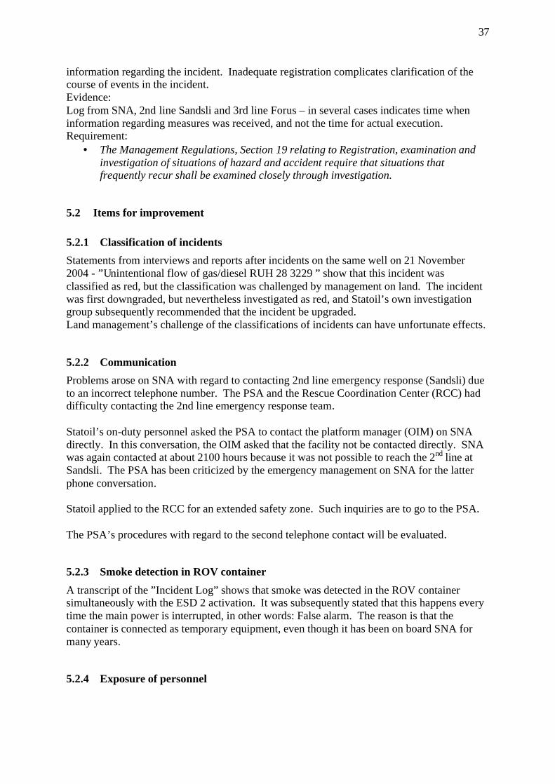
37
information regarding the incident. Inadequate registration complicates clarification of the course of events in the incident. Evidence: Log from SNA, 2nd line Sandsli and 3rd line Forus – in several cases indicates time when information regarding measures was received, and not the time for actual execution. Requirement:
• The Management Regulations, Section 19 relating to Registration, examination and investigation of situations of hazard and accident require that situations that frequently recur shall be examined closely through investigation.
5.2 Items for improvement
5.2.1 Classification of incidents Statements from interviews and reports after incidents on the same well on 21 November 2004 - ”Unintentional flow of gas/diesel RUH 28 3229 ” show that this incident was classified as red, but the classification was challenged by management on land. The incident was first downgraded, but nevertheless investigated as red, and Statoil’s own investigation group subsequently recommended that the incident be upgraded. Land management’s challenge of the classifications of incidents can have unfortunate effects.
5.2.2 Communication Problems arose on SNA with regard to contacting 2nd line emergency response (Sandsli) due to an incorrect telephone number. The PSA and the Rescue Coordination Center (RCC) had difficulty contacting the 2nd line emergency response team. Statoil’s on-duty personnel asked the PSA to contact the platform manager (OIM) on SNA directly. In this conversation, the OIM asked that the facility not be contacted directly. SNA was again contacted at about 2100 hours because it was not possible to reach the 2nd line at Sandsli. The PSA has been criticized by the emergency management on SNA for the latter phone conversation. Statoil applied to the RCC for an extended safety zone. Such inquiries are to go to the PSA. The PSA’s procedures with regard to the second telephone contact will be evaluated.
5.2.3 Smoke detection in ROV container A transcript of the ”Incident Log” shows that smoke was detected in the ROV container simultaneously with the ESD 2 activation. It was subsequently stated that this happens every time the main power is interrupted, in other words: False alarm. The reason is that the container is connected as temporary equipment, even though it has been on board SNA for many years.
5.2.4 Exposure of personnel
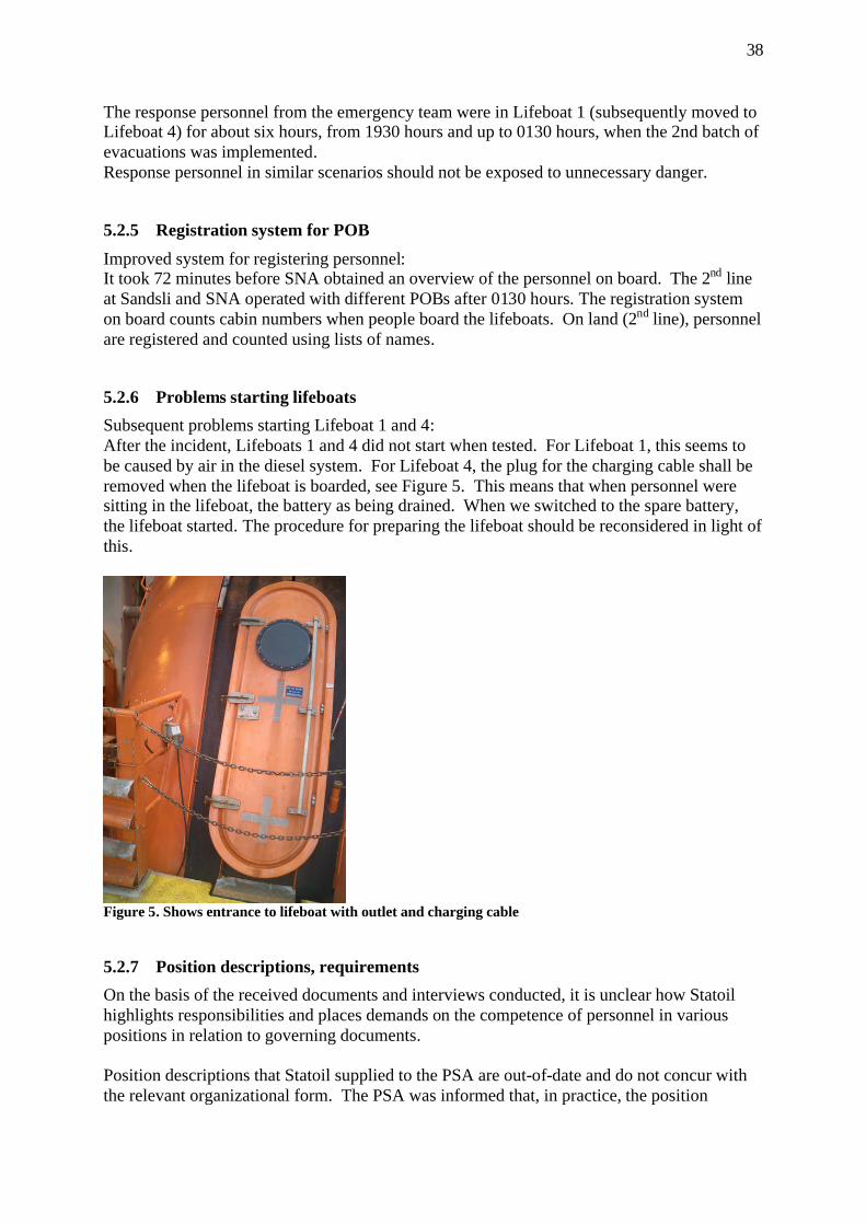
38
The response personnel from the emergency team were in Lifeboat 1 (subsequently moved to Lifeboat 4) for about six hours, from 1930 hours and up to 0130 hours, when the 2nd batch of evacuations was implemented. Response personnel in similar scenarios should not be exposed to unnecessary danger.
5.2.5 Registration system for POB Improved system for registering personnel: It took 72 minutes before SNA obtained an overview of the personnel on board. The 2nd line at Sandsli and SNA operated with different POBs after 0130 hours. The registration system on board counts cabin numbers when people board the lifeboats. On land (2nd line), personnel are registered and counted using lists of names.
5.2.6 Problems starting lifeboats Subsequent problems starting Lifeboat 1 and 4: After the incident, Lifeboats 1 and 4 did not start when tested. For Lifeboat 1, this seems to be caused by air in the diesel system. For Lifeboat 4, the plug for the charging cable shall be removed when the lifeboat is boarded, see Figure 5. This means that when personnel were sitting in the lifeboat, the battery as being drained. When we switched to the spare battery, the lifeboat started. The procedure for preparing the lifeboat should be reconsidered in light of this.
Figure 5. Shows entrance to lifeboat with outlet and charging cable
5.2.7 Position descriptions, requirements On the basis of the received documents and interviews conducted, it is unclear how Statoil highlights responsibilities and places demands on the competence of personnel in various positions in relation to governing documents. Position descriptions that Statoil supplied to the PSA are out-of-date and do not concur with the relevant organizational form. The PSA was informed that, in practice, the position
39
descriptions are no longer used, but that the requirements for the positions are defined by requirements or recommendations in governing documents. The responsibility for ensuring that personnel are trained in accordance with governing documents lies with the line manager/lead professional engineer for the discipline. Statoil should have a system that is clear enough to show connections between requirements that are stipulated for various positions, and the responsibility that governing documents define for the position. Statoil should ensure that personnel are always aware of their responsibility and have the necessary competence to carry out activities in a safe manner.
5.3 Barriers that functioned Emergency preparedness and evacuation: Manning of the emergency response center and mustering on board proceeded according to plan. The handling of the situation, with the assessments that were made during the course of the night seem to have averted a negative development of the situation. Notifications were made, measures were instituted to combat the problem, and normalization/safeguarding personnel took place in accordance with the established plans. After an evaluation of wind direction, and since there was no detection of gas on or near the helideck, use of helicopters for evacuation was considered to be prudent, also after gas was discovered on the sea. Lifeboats were not used during this incident. Use of lifeboats was, however, considered. A situation with gas blowout on the seabed is not considered to be a problem as there is the option of bringing air to the motor from inside the lifeboat (gas flasks). The evacuation was carried out in two large batches (9+3 lifts). For this purpose, a Bell 214 from Statfjord B and a Super Puma from Oseberg were used. The flight time to Stena Don and Snorre B is 3 and 4 minutes respectively.
6 ASSESSMENT AND DISCUSSION OF UNCERTAINTIES
This chapter discusses areas in which contradictory information was given during interviews, or where the investigation has been unable to uncover an exact description of the incident, or where causal relations seem to be present, although this cannot be documented. In Chapters 6.1 and 6.2, the significance of various organizational changes is discussed on the basis of an overall assessment. The PSA believes that reorganizations, use of consultants and a change in the drilling contractor may have had an impact on inadequate prioritization of resources in connection with the planning. Preparation of the program was not assigned high status, and was not considered to be a critical activity to the necessary degree. Therefore, it was never assigned priority, in spite of the fact that it involved work in a well with opening to the reservoir.
40
6.1 Drilling contractor's participation in the planning Based on interviews with the involved personnel, it emerges that the drilling contractor was not involved in any of the planning meetings before start-up of the well work. Statements indicate that the reason for this may have been the change of the drilling contractor. Odfjell Drilling, the new drilling contractor on Snorre, was mobilized at the end of October/beginning of November. 80% of the personnel followed the takeover. Subsequently, Statoil has informed us that a Prosafe toolpusher and representative from land participated in several of these meetings. This does not emerge from the submitted documents. According to the documentation, there is reason to believe that the drilling contractor did not participate in the planning in accordance with Statoil's internal requirements.
6.2 Organizational changes that are of significance for the incident Saga Petroleum ASA was the original operator for SNA. Norsk Hydro took over operator responsibility on 1 January 2000 until Statoil took over on 1 January 2003. After adjustments in connection with the takeover in January 2003 and up to the fall of 2004, there have not been major replacements in the organization. The organization has largely consisted of former Saga personnel, and some Hydro personnel. For this incident, we see that work methods have not involved expert groups from the main office, i.e. the Statoil organization in general, to any great extent. It could thus seem that the transition to Statoil's work methods and the introduction to governing documents has taken too long. During the time immediately prior to the incident and in parallel with the planning, processes were underway related to several organizational changes, both in the land organization and on SNA. There were plans for rotation of the lead drilling engineer, lead well engineer and the well operations supervisor. In addition, the senior manager for Snorre (manager RESU SN) was moving into a new position. Therefore, as planned, Snorre got a new manager on the same day that the incident took place. As regards the SNA organization, there was a planned increase in the management on board, but this was not implemented until after the incident. The program engineer who was assigned the task of preparing the well program was hired in as a consultant for Statoil. The planning was largely left up to the program engineer, without much management, guidance, involvement and prioritization from senior management. From the spring of 2004, negotiations took place regarding replacement of the drilling contractor. In November, SNA changed drilling contractor from Prosafe to Odfjell Drilling. Odfjell took over about 80 % of Prosafe's SNA personnel. Nevertheless, there were several people among Odfjell's drilling crew who were new to SNA during the incident. In addition, Statoil's drilling supervisor was on his first trip out to SNA. Reorganization, use of consultants and replacement of the drilling contractor may have had an impact on prioritization of resources in connection with the planning. In addition to the challenges in connection with the planning, the start-up of P-31A was accelerated because the work on well P32 was completed ahead of schedule. This could have led to a "stressed situation".
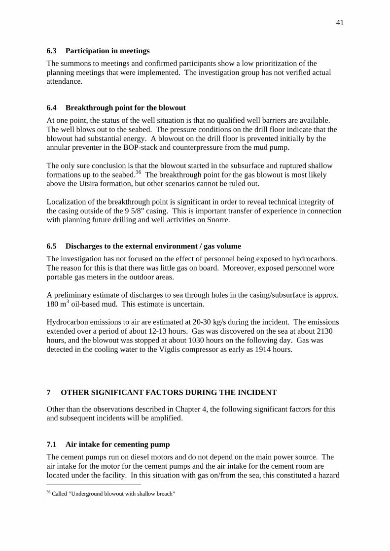
41
6.3 Participation in meetings The summons to meetings and confirmed participants show a low prioritization of the planning meetings that were implemented. The investigation group has not verified actual attendance.
6.4 Breakthrough point for the blowout At one point, the status of the well situation is that no qualified well barriers are available. The well blows out to the seabed. The pressure conditions on the drill floor indicate that the blowout had substantial energy. A blowout on the drill floor is prevented initially by the annular preventer in the BOP-stack and counterpressure from the mud pump. The only sure conclusion is that the blowout started in the subsurface and ruptured shallow formations up to the seabed.36 The breakthrough point for the gas blowout is most likely above the Utsira formation, but other scenarios cannot be ruled out. Localization of the breakthrough point is significant in order to reveal technical integrity of the casing outside of the 9 5/8” casing. This is important transfer of experience in connection with planning future drilling and well activities on Snorre.
6.5 Discharges to the external environment / gas volume The investigation has not focused on the effect of personnel being exposed to hydrocarbons. The reason for this is that there was little gas on board. Moreover, exposed personnel wore portable gas meters in the outdoor areas. A preliminary estimate of discharges to sea through holes in the casing/subsurface is approx. 180 m3 oil-based mud. This estimate is uncertain. Hydrocarbon emissions to air are estimated at 20-30 kg/s during the incident. The emissions extended over a period of about 12-13 hours. Gas was discovered on the sea at about 2130 hours, and the blowout was stopped at about 1030 hours on the following day. Gas was detected in the cooling water to the Vigdis compressor as early as 1914 hours.
7 OTHER SIGNIFICANT FACTORS DURING THE INCIDENT
Other than the observations described in Chapter 4, the following significant factors for this and subsequent incidents will be amplified.
7.1 Air intake for cementing pump The cement pumps run on diesel motors and do not depend on the main power source. The air intake for the motor for the cement pumps and the air intake for the cement room are located under the facility. In this situation with gas on/from the sea, this constituted a hazard 36 Called ”Underground blowout with shallow breach”
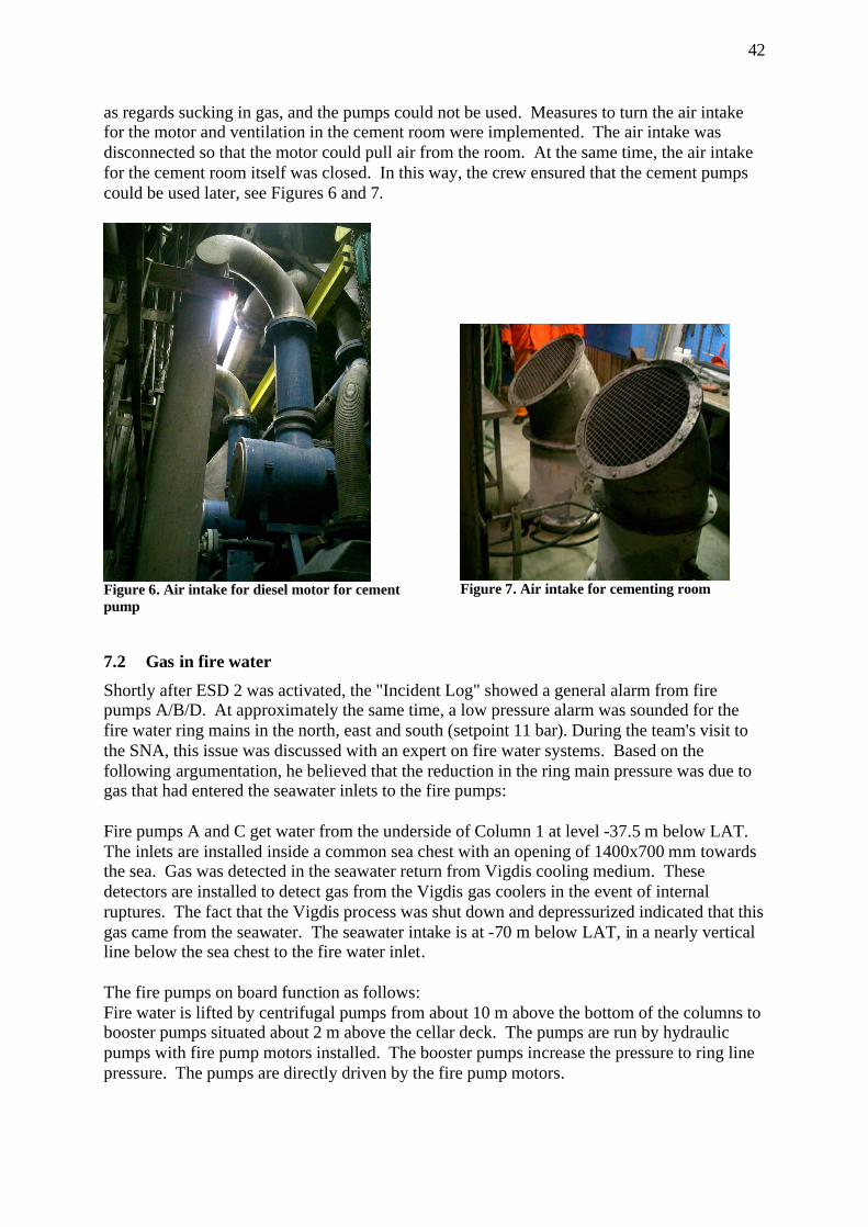
42
as regards sucking in gas, and the pumps could not be used. Measures to turn the air intake for the motor and ventilation in the cement room were implemented. The air intake was disconnected so that the motor could pull air from the room. At the same time, the air intake for the cement room itself was closed. In this way, the crew ensured that the cement pumps could be used later, see Figures 6 and 7.
Figure 6. Air intake for diesel motor for cement pump
Figure 7. Air intake for cementing room
7.2 Gas in fire water Shortly after ESD 2 was activated, the "Incident Log" showed a general alarm from fire pumps A/B/D. At approximately the same time, a low pressure alarm was sounded for the fire water ring mains in the north, east and south (setpoint 11 bar). During the team's visit to the SNA, this issue was discussed with an expert on fire water systems. Based on the following argumentation, he believed that the reduction in the ring main pressure was due to gas that had entered the seawater inlets to the fire pumps: Fire pumps A and C get water from the underside of Column 1 at level -37.5 m below LAT. The inlets are installed inside a common sea chest with an opening of 1400x700 mm towards the sea. Gas was detected in the seawater return from Vigdis cooling medium. These detectors are installed to detect gas from the Vigdis gas coolers in the event of internal ruptures. The fact that the Vigdis process was shut down and depressurized indicated that this gas came from the seawater. The seawater intake is at -70 m below LAT, in a nearly vertical line below the sea chest to the fire water inlet. The fire pumps on board function as follows: Fire water is lifted by centrifugal pumps from about 10 m above the bottom of the columns to booster pumps situated about 2 m above the cellar deck. The pumps are run by hydraulic pumps with fire pump motors installed. The booster pumps increase the pressure to ring line pressure. The pumps are directly driven by the fire pump motors.
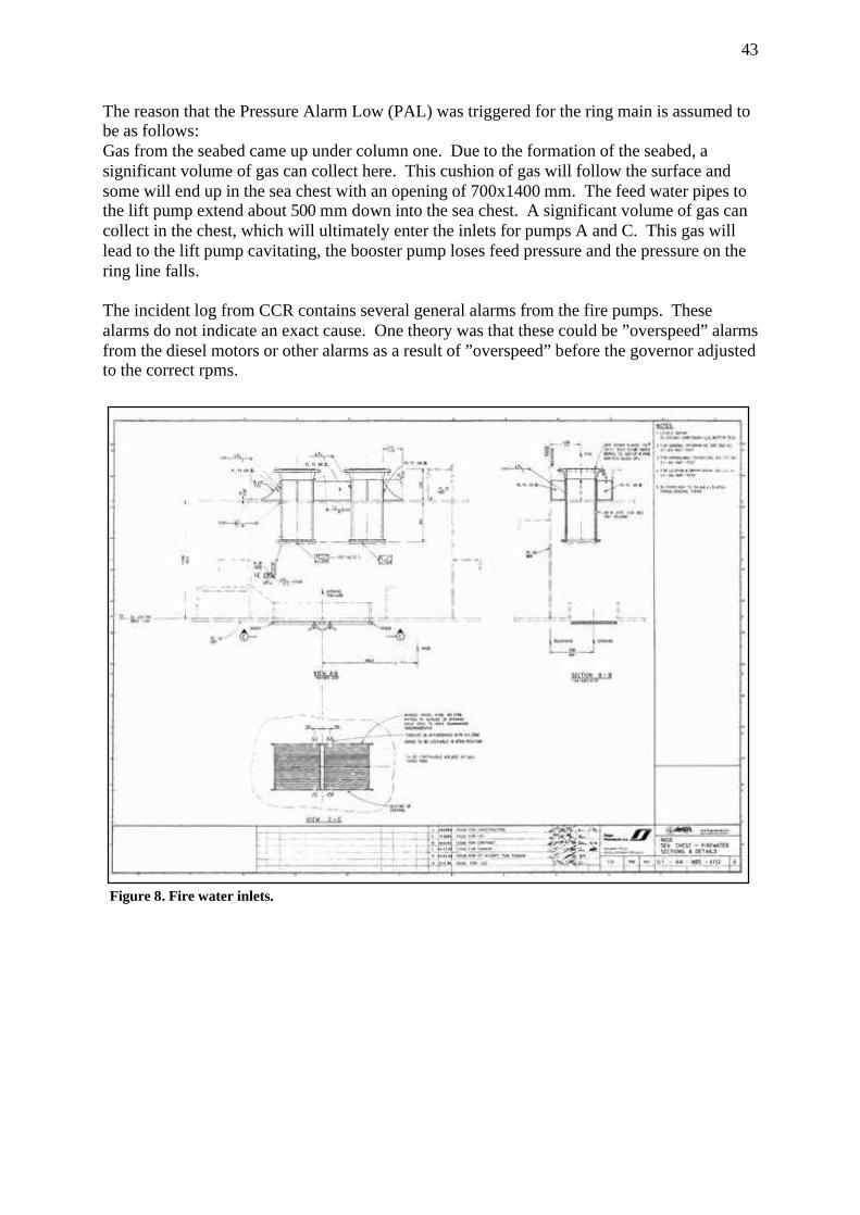
43
The reason that the Pressure Alarm Low (PAL) was triggered for the ring main is assumed to be as follows: Gas from the seabed came up under column one. Due to the formation of the seabed, a significant volume of gas can collect here. This cushion of gas will follow the surface and some will end up in the sea chest with an opening of 700x1400 mm. The feed water pipes to the lift pump extend about 500 mm down into the sea chest. A significant volume of gas can collect in the chest, which will ultimately enter the inlets for pumps A and C. This gas will lead to the lift pump cavitating, the booster pump loses feed pressure and the pressure on the ring line falls. The incident log from CCR contains several general alarms from the fire pumps. These alarms do not indicate an exact cause. One theory was that these could be ”overspeed” alarms from the diesel motors or other alarms as a result of ”overspeed” before the governor adjusted to the correct rpms.
Figure 8. Fire water inlets.
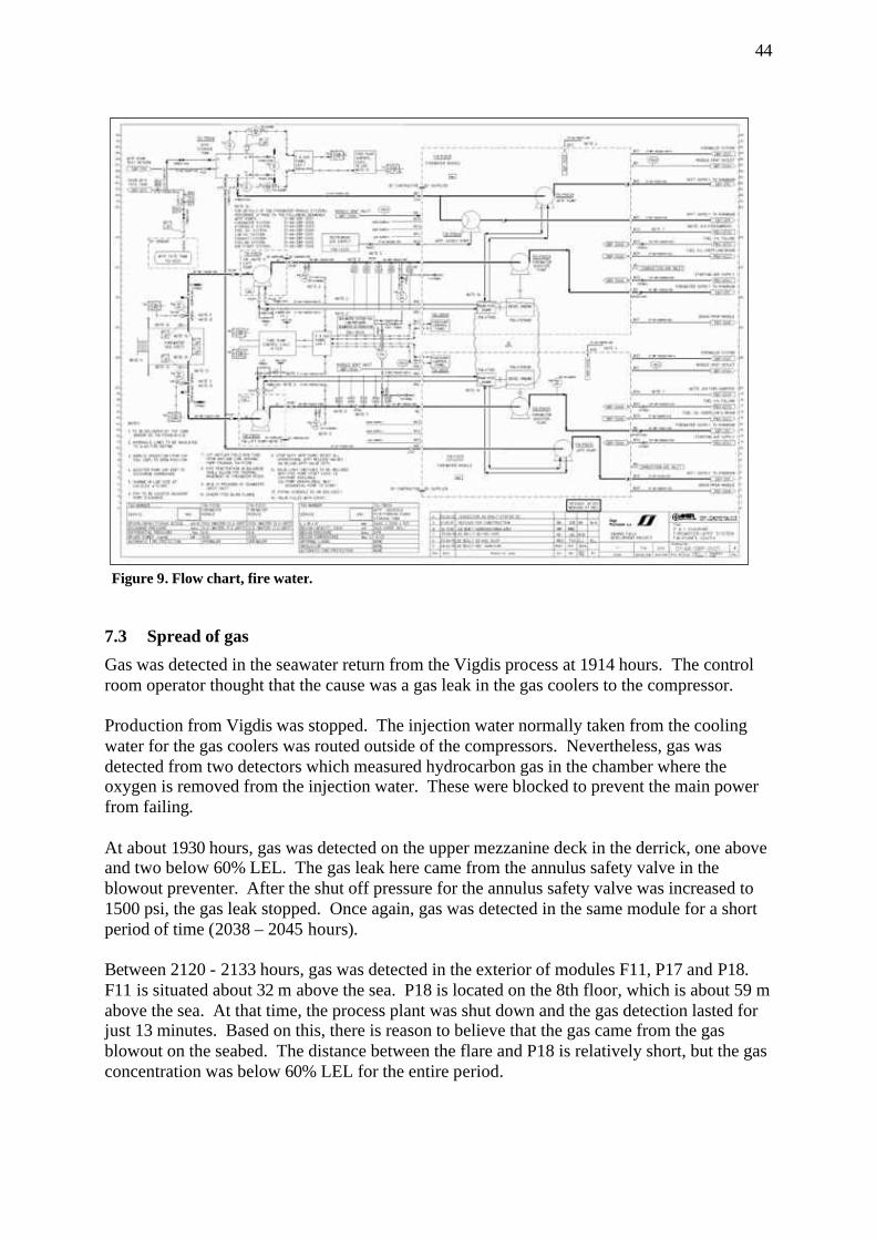
44
7.3 Spread of gas Gas was detected in the seawater return from the Vigdis process at 1914 hours. The control room operator thought that the cause was a gas leak in the gas coolers to the compressor. Production from Vigdis was stopped. The injection water normally taken from the cooling water for the gas coolers was routed outside of the compressors. Nevertheless, gas was detected from two detectors which measured hydrocarbon gas in the chamber where the oxygen is removed from the injection water. These were blocked to prevent the main power from failing. At about 1930 hours, gas was detected on the upper mezzanine deck in the derrick, one above and two below 60% LEL. The gas leak here came from the annulus safety valve in the blowout preventer. After the shut off pressure for the annulus safety valve was increased to 1500 psi, the gas leak stopped. Once again, gas was detected in the same module for a short period of time (2038 – 2045 hours). Between 2120 - 2133 hours, gas was detected in the exterior of modules F11, P17 and P18. F11 is situated about 32 m above the sea. P18 is located on the 8th floor, which is about 59 m above the sea. At that time, the process plant was shut down and the gas detection lasted for just 13 minutes. Based on this, there is reason to believe that the gas came from the gas blowout on the seabed. The distance between the flare and P18 is relatively short, but the gas concentration was below 60% LEL for the entire period.
Figure 9. Flow chart, fire water.
45
7.4 Effect of reduced power supply The power supply was normal up until the Emergency Shut Down (ESD 2) was activated. The main power was stopped in connection with the emergency shut down. The two emergency power generators started automatically. Main power amounts to a total of 82 MW (3 x 20 MW and a cable from Snorre B carrying 22 MW). After the emergency shut down, available power was supplied from two emergency generators, in a total amount of 4 MW. The cable from Snorre B was also disconnected. This reduction of power supply led to some practical problems, such as:
• The capacity of the mud pumps was reduced to 1/6 of normal, and all operations in the drilling area took significantly longer than normal. This complicated implementation of an effective well control operation.
• All ventilation systems stopped. • Rooms protected with overpressure/underpressure lost their overpressure/
underpressure. (In the event of gas outside such rooms, the equipment in the room is disconnected).
• Reduction to one air compressor powered by the emergency generators. In addition, the emergency air compressor in Module D45 was started manually.
Main power was restarted around midnight, which was considered to be a risky operation. After an overall evaluation, including emphasis on the fact that no gas was detected on the facility after 2133 hours, the main power was restored. The following areas were then powered up:
• Drilling area • Auxiliary equipment area • Living quarters module
For the living quarters module, the air intake was turned so that it took in air above the roof of the living quarters module. In Uninterruptible Power Supply (UPS) room F11, recirculation of air was run in the room. The recirculation system in the UPS room in F51 did not work. Here the doors were opened and personnel kept watch.
7.5 Flaring and depressurization The pipeline that leads the gas from the knock-out drum to the flare is purged with nitrogen during normal operations. This prevents air from entering the pipe and thus creating an explosive mixture of gas/air. Nitrogen is produced in a separate plant on the facility. In addition, there is a pilot flame that burns continuously at the top of the flare boom. This will ignite combustible gases that might come out of the pipeline from the knock-out drum. This happens during situations such as depressurization of pipelines and the process plant. In this incident, depressurization of the gas compressors started automatically when PAS 3.4 was triggered at 1935 hours. Manual depressurization was implemented 25 minutes after NAS 2 was activated at 2150 hours. The flare could not be extinguished, because there was not enough nitrogen on board. There was some nitrogen to extinguish the flame, but not enough to cool the tip of the flare. This would have led to immediate self-ignition when HC gases again moved up the flare. It took a
46
long time before the flame was so small that the flare could be extinguished without a danger of self-ignition. The flare on SNA burned during the incident, and according to the Snorre CCR log, it was confirmed as being extinguished at 0315 hours. The depressurization started with Vigdis. Ten minutes later, manual depressurization of the gas export riser from Snorre B (SNB) commenced. This pipeline was depressurized from SNB, but due to problems with a valve on the seabed, only the pipeline from SNB was depressurized down to this valve. The rest of the pipeline was left standing with pressure up to the emergency shut down valve on SNA. Depressurization of the gas export pipeline to Statfjord A started from Statfjord A at 2207 hours. Two minutes later, depressurization of the gas export line on SNA also got underway. The process plant on SNA started depressurization at 2217 hours. During the course of the incident, the flaring was considered to be a potential source of ignition for the gas from the sea. Consideration was given to "cold flaring", but without main power, there was not nitrogen available to extinguish and cool down the flare. It was also uncertain whether the nitrogen plant would be able to deliver sufficient volumes of nitrogen for this purpose.
7.6 Danger of loss of stability and buoyancy With regard to buoyancy and stability, this was followed up by a different group from the PSA. The investigation group was kept informed regarding the status. Here we have only included factors related to the actual blowout. The incident occurred during good weather conditions. We have not assessed possible additional consequences if the incident had happened during a storm.
7.6.1 Loss of tension leg through uplift of the foundations Personnel who were evacuated expressed concern about the buoyancy. If one foundation had started to move so that the tension legs lost their moorings, it is possible that the SNA would have gone down. The SNA facility is designed to withstand the loss of two of four wires in one leg, but not all of them in one corner. The emergency response management on board ensured that the tension in each of the legs was monitored from the central control room. This remained unchanged throughout the entire blowout. Afterwards, however, it was ascertained that there had been a minor change in the tension of one or more tension legs (Statoil: Evaluation of measured tension balance errors during the gas blowout). Subsequent surveys of the seabed show a crater on the west side of the well template (hole 10) measuring 8 m x 3 m, as well as two craters with diameters of 2.5-3 m (hole 4 and hole east), see Figure 10. In addition, several smaller craters have been noted in the direction towards the northwestern foundation. The closest crater was approx. 30 cm from the wall of the foundation, while the crater with a diameter of 3 m is situated on the east side, i.e. above the well path. These craters indicate great force. The depth of the craters may be all the way down to the site of the leak. The foundation of the tension legs consist of three cylindrical concrete cylinders welded together. The diameter of the cylinders is 17 m and they have been driven 12-13 m down into
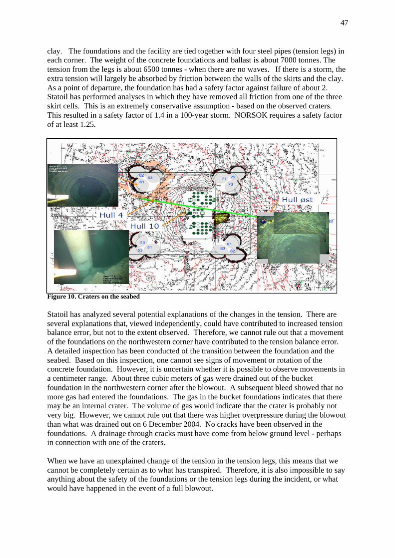
47
clay. The foundations and the facility are tied together with four steel pipes (tension legs) in each corner. The weight of the concrete foundations and ballast is about 7000 tonnes. The tension from the legs is about 6500 tonnes - when there are no waves. If there is a storm, the extra tension will largely be absorbed by friction between the walls of the skirts and the clay. As a point of departure, the foundation has had a safety factor against failure of about 2. Statoil has performed analyses in which they have removed all friction from one of the three skirt cells. This is an extremely conservative assumption - based on the observed craters. This resulted in a safety factor of 1.4 in a 100-year storm. NORSOK requires a safety factor of at least 1.25.
Figure 10. Craters on the seabed Statoil has analyzed several potential explanations of the changes in the tension. There are several explanations that, viewed independently, could have contributed to increased tension balance error, but not to the extent observed. Therefore, we cannot rule out that a movement of the foundations on the northwestern corner have contributed to the tension balance error. A detailed inspection has been conducted of the transition between the foundation and the seabed. Based on this inspection, one cannot see signs of movement or rotation of the concrete foundation. However, it is uncertain whether it is possible to observe movements in a centimeter range. About three cubic meters of gas were drained out of the bucket foundation in the northwestern corner after the blowout. A subsequent bleed showed that no more gas had entered the foundations. The gas in the bucket foundations indicates that there may be an internal crater. The volume of gas would indicate that the crater is probably not very big. However, we cannot rule out that there was higher overpressure during the blowout than what was drained out on 6 December 2004. No cracks have been observed in the foundations. A drainage through cracks must have come from below ground level - perhaps in connection with one of the craters. When we have an unexplained change of the tension in the tension legs, this means that we cannot be completely certain as to what has transpired. Therefore, it is also impossible to say anything about the safety of the foundations or the tension legs during the incident, or what would have happened in the event of a full blowout.
48
7.6.2 Loss of buoyancy of the hull in connection with upward flow of gas Models of gas emissions under water show that huge emissions of gas are required before the percentage of gas on the surface becomes dangerous. At water depths of 300 meters, the gas will spread out and only parts of the gas will reach the surface of the sea close to the facility. The extent of the gas on the surface will depend on factors such as the strength of the sea currents. As regards the danger of loss of buoyancy and stability on loosely moored facilities, studies by Sintef and observations indicate that the flow will result in a "fountain effect" that pushes facilities/vessels up and away from the area (ref. surveys and experience on Jotun, Åsgard and West Vanguard). However, this is not so simple for a tension leg facility like the SNA. The SNA will not be lifted up. If the SNA was pulled out, the tension legs would then help pull the facility back towards normal position. The facility would then move until equilibrium was achieved between the forces that would push it out (the gas stream) and the tension legs, which would pull it in again. In our opinion, increased tension in the tension legs as a result of the gas flow (when the dynamic link is greater than the reduction in density) would be just as likely a scenario as loss of buoyancy.
8 OTHER STUDIES
The investigation group's mandate calls for the group to identify the need for assistance, separate studies and the use of consultants.
8.1 Need for additional studies The following studies are being considered to further elucidate the causal relations of the incident.
• Pressure response, well operations and during well control situation for this incident • Casing wear / Well design / Well barriers • Increased buoyancy / fountain effect from the gas stream • Loss of / reduced buoyancy due to gas bubbles • Gas under the bucket foundations under various design conditions • Excavation of and craters in the bucket foundations; • Loss of suction under the bucket foundations in the event of cracking or damage.
9 ABBREVIATIONS
AR Activity requirement B&B Drilling and wells BOP Blow out preventer CCR Central Control Room HAZOP hazard and operability study (Risk analysis) LEL Lower Explosion Limit mMD meters Measured Depth
49
MTO Man - Technology - Organization causes (investigation methodology) NAS Emergency Shut Down System PA Public Announcement PAS Process shut down system POB Personnel On Board PSA Petroleum Safety Authority Norway RCC Rescue Coordination Center RESU subsurface groupReservoir recovery ROV Remote operated vehicle RUH Reporting of undesirable incident s.g. Specific gravity SNA Snorre A SN-RE Snorre result unit UPA Subsea production facility UPS Uninterruptible power supply WBM Water Based Mud WR Work recommendation WD Work description
10 APPENDICES
Appendix 1 MTO Diagram Appendix 2 Overview of documents Appendix 3 Interview subjects

50
Appendix 1 MTO Diagram
51
Appendix 2 Overview of documents Document log in connection with investigation of the incident on Snorre 34/7-P31-A 1. Item 1994/5054 -1, Well program 3417-P-31, Saga Petroleum a.s. 2. Item 1994/5054-4, Final Well Report 34/7-P-31 Saga Petroleum a.s. 3. Item 1994/5430-1, Well program 34/7-P-31A Saga Petroleum a.s. 4. Item 1994/5430-2, Change in drilling program of 20 December 1994 5. Item 1994/5430-4, Updated pages of drilling program of 29 December 1994 6. Item 1994/5430-8, Completion report of 15 June 1995 7. Item 1994/5430-9, Information on temporary isolation of 21 August 1995 8. Item 1994/5430-10, Updated well drawing of 25 August 1995 9. Item 1994/5430-11, Final well report Snorre TLP of 16 October 1995 10. Item 1994/5430-12, Updated well drawing of 4 December 1995 11. Item 1994/5430-13, Updated well drawing of 14 February 1996 12. Snorre A Slot Recovery Program 34/7-P-31 A, RA-Snorre-00219, November 2004 13. Snorre A-P-31 A Pull completion & prepare for side-track, Statoil 14. Snorre A-P-31 A Slot Recovery Operation – Schematics 15. Snorre Field Development Project, Geotechnical design premises S1-CC-YSD -0300 rev 0 16. Subject: Stability in the blowout 17. TLP Drilling Riser System 18. Drilling 60 Days Schedule – Week 48, 60d Schedule – SN Drilling and well action. Plan 19. Statoil governing document APP V Snorre A Emergency preparedness organization, WR1480,
version 1.01, valid from 4 February 2003 20. Organization chart, Operation Norway. Odfjell Drilling rev. 1 November 2004 21. Organization chart, UPN TO, Statoil, Last modified 29 November 2004 22. Risk assessment: P-31A – Retrieve 7 5/8’’ scab liner, updated 25 November 2004 23. Risk assessment: P-31 A – Drop 5 ½’’ tubing/ 4’’ straddle, updated 25 November 2004 24. Drawing – Snorre, NOC tension reinforcement 25. Drawing – General drawings well, well area, with manifold systems 26. WR 0442 ”Planning of Drilling & Well Operations” 27. AR03, Drilling, well and production activities 28. WR0536 Requirements to well fluids and related equipment 29. WR0221 Hand-over of wells, plus supplement "Supplement to Hand-over of wells” Snorre SNA 30. WR0530 Well Control – well interventions 31. WR0436 Drilling and completion operations 32. Incident Log, Alarm List 1 33. Incident Log, Alarm List 2 (omitted, included in Doc. 32) 34. POB list, Personnel on board when the incident occurred, 28 November 2004, received 3
December 2004 35. Journal transcript, Normand Mjølne, 1 December 2004, received 3 December 2004 36. Log from Ocean Knarr, journal excerpt for Sunday, 28 November 2004, received 3 December
2004 37. Experiences with gas blowout in well P 31. SNA OIM 38. E-mail from SNA drilling supervisor with info on response to inquiries to land organization.
About 7 5/8 liner through BOP/well barriers (Excerpt of WR0436) 39. WD0609 Well work in Snorre reservoir 40. Emergency response log, 2nd line Sandsli (Statoil) 41. E-mail from Statoil's regulatory coordinator, with Log from 2nd and 3rd line and central control
room log. 42. USIT/CBL - log from 18 March 1995 Schlumberger MAXIS 500 Field log (2CDs) 43. Checklist alarm /exercise Snorre platform (checklist for notification) 44. Helicopter information Snorre TLP 45. Baker Hughes INTEQ Mud log P-31A 27 November - 2 December 2004 46. Odfjell Drilling “Driller's Golden Rules” of 12 June 2003
52
47. Exemption Synergi No. 36064 for well 34/7-P-26 48. E-mail from SNA safety supervisor: Power point presentation with visualization of gas leak,
evacuation and well fighting 49. Notes from program engineer (notebook with relevant papers from the program engineer) 50. Cementing problems. Doc id RA 95-191/SBB Saga Petroleum AS 51. Gas flow report, Unintended flow of gas/diesel RUH 283229 52. E-mail from SNA construction manager re: low pressure in fire water 53. Statoil's investigation report with appendices (doc 2240-61) no print-out 54. Detailed program for Snorre 34/7-P-31 A - Signed interim procedure pull string 55. E-mail: Reply from program engineer to drilling supervisor SNA of 23 November 2004 56. Pictures of action board SNA 28-29 November 2004 (doc. no. 2240-17) 57. Safety supervisor's notes in connection with "Well P-31 out of control” 58. ROV film Oceaneering 59. Video log Oceaneering 60. Snorre A RESU transcript from MIS (Goal management in Statoil) 61. E-mail from SNA safety supervisor: Experience from SNA lifeboat captain 62. E-mail to JAN/PSA of 29 November 2004: Application for extended safety zone 63. Position descriptions a) RESU manager (Snorre) b) RESU unit manager (Snorre A) c) Drilling operations supervisor d) Drilling supervisor e) Lead drilling and well engineers f) Drilling engineers 64. WR0011 ”Exemptions, improvement and non-conformities” Procedure for handling non-
conformities 65. Report from internal audit Snorre RESU in 2003 (conducted by process owner B&B) 66. Report from internal audit Snorre RESU in June 2004 (conducted by process owner B&B) 67. Position description, operations engineer 68. ”Snorre CCR log”. (Pages 165-168)

53
Appendix 3 Interview subjects (Exempt from publication)


![YOUNGER EDDAS OF SNORRE STURLESON.heathengods.com/library/prose_edda/BlackwellProseEdda.pdf · 2007. 12. 15. · THE YOUNGER EDDAS OF STURLESON. THE DELUDING OF GYLFI. GEFJON'S PLOUGHING.[125]](https://img.dokumen.tips/doc/110x75/61225bdda07d564e784d2154/younger-eddas-of-snorre-2007-12-15-the-younger-eddas-of-sturleson-the-deluding.jpg)