Embed Size (px)
Citation preview

Investigation of Fatigue Crack Growth under
Pure Mode-I and Mixed Mode
Mr. Naresh M. Kalsaria Student, ME-CAD/CAM,
Department of mechanical engineering,
Shree S ’ad Vidya Mandal Institute of Technology,
Bharuch, Gujarat, India
Mr. Chetan S. Jadav Assistant Professor,
Department of mechanical engineering,
Shree S ’ad Vidya Mandal Institute of Technology,
Bharuch, Gujarat, India
Abstract— It is very difficult to find out the exact failure and
fracture mechanism in complex devices. An attempt is made to
predict the fatigue crack growth using finite element analysis to
design a body against fatigue failure. In the present study, Pure
Mode-I and Mixed Mode fatigue crack are analyzed and
experimented by using simple fixture which assembles the
specimen to machine. Fatigue crack growth test in Mixed Mode
carried out for several load ratio on IS 2062 Grade A (E-250)
with 5 mm thickness. The tests were performed in standard
Servo-hydraulic Machine. The fatigue crack path obtained by
ABAQUS software was compared with experimental data.
Based on experimental and simulation work, it is found that as
inclination angle of crack increases, it requires more load for
initiation of the crack so it will increases the fatigue life.
Keywords—Mixed-mode Loading, Fatigue Crack growth rate,
Fatigue Crack Path
I. INTRODUCTION
Fatigue crack growth is the most common failure
mechanism in mechanical structure or component since they
are usually subjected to cyclic loads.
In the past, many investigators have carried out research on
sub critical propagation in metallic material. This was
primarily motivated by need of fatigue crack growth rate data
for their reduction of services live for structure subjected to
cyclic stresses, especially for structure that contained
fabrication imperfection. The study of fatigue crack
propagation examines how fatigue grows under cyclic load
[12].
The majority of the fatigue crack growth is usually performed
under mode-I loading condition. In many practical cases are
not normal to the maximum principal stress condition
prevails at the tip of such crack. This type of loading is very
commonly encountered when crack deflection occurs during
crack growth [10].
Many ship-building components, marine structure, turbine
shaft, and railways track etc have complex parts which are
often subjected to combined loading such as bending, torsion,
and tension. These parts always go under variable loads so if
there is crack in the material; it will be mixed mode fatigue
crack [11].
Many different specimen geometries have been used to
produce different combination of mixed-mode loading under
different test condition, in the real situation defects/cracks
which is present in the structure or components are not
necessarily in mode of opening. They may be in the mixed
condition such as mode (I+II), mode (I+III), or Mode
(I+II+III). The need for adopting new methods of damage
assessment incorporating the effect of mode of loading is
being increasingly recognized. Therefore, suitable FCG rate
(Paris Type) law is require predicting the life of the
component or structure under mixed mode loading [1].
Fatigue life has been considered to be composed of
three phases:-
1) Crack Initiation
2) Stable Crack Propagation
3) Final Failure (Rapid Fracture)
A. TYPES OF FATIGUE
There are mainly three commonly recognized forms of
fatigue:-
High Cycle Fatigue (HCF)
Low Cycle fatigue (LCF)
Thermal Mechanical Fatigue (TMF)
High Cycle Fatigue (HCF):- HCF is characterized by low
amplitude high frequency elastic strain. An example would
be an aero-foil Subjected to repeated bending. One source of
this bending occurs as a compressor or turbine blade passes
behind a stator vane. When the blades emerge into the gas it
is bent by high velocity gas pressure. Change in rotor speed
change the frequency of blade loading [4].
Low Cycle Fatigue (LCF):- LCF is the mode of material
degradation when plastic strains. For example if we pull the
beam of the tuning fork apart until they are permanently bent
we have imparted one half of an LCF [4].
Thermal Mechanical Fatigue (TMP):- In the case of TMF
(present in turbine blades, vanes and other hot section
components) large temperature changes result in significant
by thermal expansion and contraction and therefore
significant by thermal expansion and contraction. This strain
are reinforced or countered by mechanical strains associated
with centrifugal loads as engine speed changes. The
combination of these events causes material degradation due
to TMF [4].
International Journal of Engineering Research & Technology (IJERT)
ISSN: 2278-0181
www.ijert.orgIJERTV4IS050849
( This work is licensed under a Creative Commons Attribution 4.0 International License.)
Vol. 4 Issue 05, May-2015
765

B.DIFFERENT MODE FOR CRACK LOADING
There are mainly three mode of the Crack Loading
Mode-I: - This mode of loading knows as crack opening
Mode or Tensile. The crack surface moves directly apart. It
is most common type mode encounter in most of
engineering design.
Mode-II: - This mode knows as in plane shear mode. Where
the crack surface slides over one another in a perpendicular
to leading edge of the crack.
Mode-III: - This mode knows as out of the plane shear mode.
Where the crack surface slides over one another in a
perpendicular to leading edge of the crack.
Fig:-1 Three Different mode of Crack Loading
II. LITERATURE REVIEW
M. Nani Babu had work done on the evaluation of FCG
behavior of SS316L (N) under mixed mode loading
condition. The FCG data for mixed mode have been
compare with pure mode-I. The crack length measurement
was carried out using a suitably calibrated direct current
potential (DCPD) system. They concluded that when the
loading angle is increase the fatigue crack growth
decrease. At loading all three models appear successful
[1].
Rohinkumar I. Patel and Chetan Jadav had been presented
the investigated of the fatigue crack growth rate of thin
plate. For find out crack growth path under the constant
amplitude loading. Further FEA analysis is done by XFEM
based algorithm available in the finite element code
ABAQUS is explored with respect to its performance in
estimating crack growth Paths [2].
H.A. Richard had an overview about theories, experiments
and simulation of crack and crack growth under mixed
loading condition. They have been described some concept
and theories for two dimensional and three dimensional
crack in mixed mode situation. Experiments for 3D mixed
mode problems are very difficult to perform. Based on the
theoretically and experimentally results are compared. For
crack growth simulation three dimensional programs
ADAPCRACKD used [3].
Nirepesh vikaram and Raghuvir Kumar had been focused
on crack propagation in fatigue and its numerical analysis
using Fem published since 19th
century and identified new
research lines. Based on the literature review they
conclude that the fatigue crack growth rate equation
expressed in term of the stress intensity factor range K
deepened on the R-ratio. They observed that some
researcher have found that U is a function R only, and is
independent of other parameters for a material. Specimen
geometry and material properties are found to affect crack
growth rate. Nowadays also crack closure was still
considered to be the leading mechanism to arrive at
effective in stress range [4].
Rahman Seifi and Naser Omidvar had been focused on the
fatigue crack growth affected by some parameters such as
inclination angle, pre-crack length, load ratio and
thickness. The crack growth path, fracture surface and
stress intensity factor along crack front are studied by the
numerically and experimentally. Based upon the
experimental work and numerical calculation found that
FEM will be accurate for study of mixed mode fatigue
crack growth. Fatigue lives increase by increasing the
crack angle and decreasing the pre crack length. The stress
intensity factor for all modes increases when the length of
pre-crack increases and by increasing the thickness and
loads ratio, the SIF values decreases for all modes [5].
Pukar T. Sanjay and Pathak Sunil had focused on the
capability and limitation for predicting the crack
propagation trajectory and the stress intensity factor value
under linear elastic fracture analysis. In this work the main
purpose of serving optimum design of structure against
fatigue failure and the fatigue crack path. Circular hole in
rectangular plate and double notched plate were consider
under mode-I loading using and adaptive mesh finite
element strategy. Finally they concluded numerical finite
element analysis with displacement exploration method
have been successfully employed for linear fracture
mechanics problem [6].
Lichun Bian and Farid Taheri had been observed the crack
initiation and propagation in rectangular and theoretically.
Based on the different criteria, a detailed analysis of
fatigue crack initiation and propagation under mixed mode
loading condition as commonly encountered in
encountered in engineering structure. They consider that
the Z-criterion is effective and offers acceptable estimation
in predicting the mixed mode fatigue crack propagation
[7].
Ki-Jeong Seo was investigate on the fatigue crack growth
with/without a circular micro defect under the mixed mode
International Journal of Engineering Research & Technology (IJERT)
ISSN: 2278-0181
www.ijert.orgIJERTV4IS050849
( This work is licensed under a Creative Commons Attribution 4.0 International License.)
Vol. 4 Issue 05, May-2015
766
loading condition is through experiments and analyzed by
linear elastic finite element (FE) analysis. In this work
simulated crack path observed through experiment. In this
studied three loading angle and two cases of the sample
with circular micro defect are selected. Based on the
experimental work, they concluded that the crack growth
rate increases when the crack entre in to micro-defect. On
the other side when the crack does not entre the micro
defect, the effective rang of stress intensity factor can be a
better parameter for explaining the crack growth rate [8].
J.M. Alegre was work done on the modeling of crack
propagation through a finite element mesh under mixed
mode condition and the effect of mesh size in the crack
path estimate also analyzed. The effect of initial crack
angle on the experiment results showed that development
of the crack propagation [9].
Luca Susmel and David Taylor had done work on the non-
propagating crack were generated under different Mode-I
and mode-II stress components. They concluded that crack
length tended increase as the mode-II contribution to
fatigue damage increased. They used linear elastic stress
analysis, are useful tool for the prediction of fatigue limit
under mixed mode in phase loading condition [10].
L.P. Borrego was presented work on the correlation of the
equalient value of effective stress intensity factor with
crack growth rate. They have been concluded when load
direction modified the fatigue crack growth rate direction
change immediately from the initial notch orientation.
Under the mixed mode loading condition the crack closure
increase compare to mode-I loading condition. From the
experiment they have been concluded that the lower crack
closure level are obtain by the elastic-plastic finite element
analysis relatively to measure value at high load direction
angle mainly due to roughness induced closure [11].
M. Sander and H.A. Richard gave an idea about fatigue
crack growth under variable amplitude loading in real
structure is modeled using elastic-plastic finite element
analysis. Based on the numerical and simulation study it
can be concluded that the crack closure is very important
factor for the fatigue crack growth. By a mixed mode
overload the crack deformation become asymmetrical and
smaller [12].
III. EXPERIMENTAL AND FINITE ELEMENT ANALYSIS
Modeling was done with Cre-o and analysis was
carried out using ABAQUS, a commercially available FE
analysis programed. The material used in this study was one
of commercial-grade hot-rolled Mild steel (IS 2062 Grade-A
E-250) which is popularly used in Boiler, Furnaces and
Automobile parts. Physical parameters of plate, material
properties and Chemical composition of material are given
below.
A. Physical parameters of component
Table:-1
1. Length (mm) 115
2. Width (mm) 50
3. Thickness (mm) 5
4. Length of Crack (mm) 15
5. Thickness of Pre-Crack (mm) 0.36
B. Material properties of IS 2062 Grade-A (E-250)
Table:-2
Yield strength (MPa) 250
Elongation 23
Poisson’s ratio 0.30
Tensile Strength (MPa) 410
C. Chemical composition of IS 2062 Grade-A (E-250)
Table:-3
C % Mn % S % P % Si % CEV %
0.149 0.148 1.034 0.021 0.012 0.328
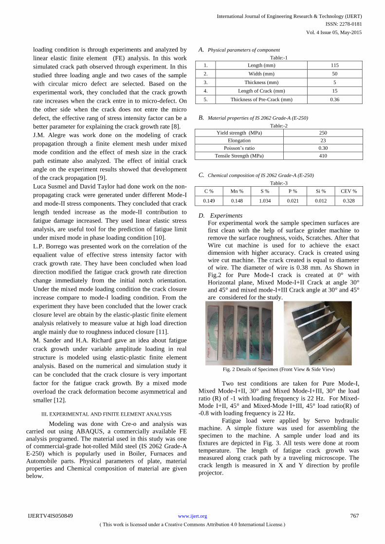
D. Experiments
For experimental work the sample specimen surfaces are
first clean with the help of surface grinder machine to
remove the surface roughness, voids, Scratches. After that
Wire cut machine is used for to achieve the exact
dimension with higher accuracy. Crack is created using
wire cut machine. The crack created is equal to diameter
of wire. The diameter of wire is 0.38 mm. As Shown in
Fig.2 for Pure Mode-I crack is created at 0° with
Horizontal plane, Mixed Mode-I+II Crack at angle 30°
and 45° and mixed mode-I+III Crack angle at 30° and 45°
are considered for the study.
Fig. 2 Details of Specimen (Front View & Side View)
Two test conditions are taken for Pure Mode-I,
Mixed Mode-I+II, 30° and Mixed Mode-I+III, 30° the load
ratio (R) of -1 with loading frequency is 22 Hz. For Mixed-
Mode I+II, 45° and Mixed-Mode I+III, 45° load ratio(R) of
-0.8 with loading frequency is 22 Hz.
Fatigue load were applied by Servo hydraulic
machine. A simple fixture was used for assembling the
specimen to the machine. A sample under load and its
fixtures are depicted in Fig. 3. All tests were done at room
temperature. The length of fatigue crack growth was
measured along crack path by a traveling microscope. The
crack length is measured in X and Y direction by profile
projector.
International Journal of Engineering Research & Technology (IJERT)
ISSN: 2278-0181
www.ijert.orgIJERTV4IS050849
( This work is licensed under a Creative Commons Attribution 4.0 International License.)
Vol. 4 Issue 05, May-2015
767

Fig. 3 A sample with proper fixture before test and during test
E. Finite element Analysis
A commercial FE analysis program ABAQUS is used for
the computation of fatigue crack path. First, Model of plate
with different modes is created using Cre-o software.
ABAQUS software is used for analyzing different condition
to get accurate results.
Fig. 4 Meshed View of plate for Mixed Mode-I+II, 30°
As shown in Fig.4 by increasing the number of elements, the
fatigue path gets more accurate. In figure demonstrates a
meshed blade with 12860 elements generated.
III. RESULTS AND ANALYSIS
In below figures, the comparison between the crack
paths obtained by the experimental and FE analysis is shown
for all cases are considered for carrying work.
Fig.:- (a) For pure Mode-I after failure
Fig.:- (b) For Mixed Mode-I+II, 30° after failure
Fig.:- (c) For Mixed Mode-I+II, 45°
Fig.:- (d) For Mixed Mode-I+III, 30° after failure
Fig.:- (e) For Mixed Mode-I+III, 45° after failure
International Journal of Engineering Research & Technology (IJERT)
ISSN: 2278-0181
www.ijert.orgIJERTV4IS050849
( This work is licensed under a Creative Commons Attribution 4.0 International License.)
Vol. 4 Issue 05, May-2015
768

Fig.:-(f) Crack growth incrases for Mode-I
Fig.:-(g) Contours deform shape for Mode-I
Fig.:- (h) Crack path for Mixed Mode-I+II, 30°
Fig.:- (i) Crack path for Mixed Mode-I+II, 45°
Fig.:- (j) Crack path for Mixed Mode-I+III, 30°
Fig.:- (k) Crack path for Mixed Mode-I+III, 4
A. Compare results of Experimental Vs. FEA Crack Length
Below graph shows the fatigue crack length on Y axis
versus crack length on X axis. It is compare experimental
data versus simulation data. In which the blue line
indicate experimental data and red line indicate
simulation data. The result shows these lines are all most
identical but having some negligible amount of
difference.
Fig. 5 Graphical Representation for Mode-I
International Journal of Engineering Research & Technology (IJERT)
ISSN: 2278-0181
www.ijert.orgIJERTV4IS050849
( This work is licensed under a Creative Commons Attribution 4.0 International License.)
Vol. 4 Issue 05, May-2015
769

Fig. 6 Graphical Representation for Mixed Mode-I+II, 30°
Fig. 7 Graphical Representation for Mode-I+II, 45°
Fig. 9 shows Compressions of the simulation data Vs
experimental data. Experimental data taken as average both
side cracks on plate.
Fig. 8 Graphical Representation for Mode-I+III, 30°
Fig. 9 Graphical Representation for Mode-I+III, 45°
B. Compare Fatigue Number of cycle Vs Crack Length
Below graph shows the comparison between Number of
Cycle versus crack length. Compare Mode-I with Mixed
Mode-I+II, 30° and Mixed Mode-I+II, 45°. For mixed
Mode-I+II, 45° Load ratio is -0.8. A result shows that
when any part under Mixed Mode and having more
inclination angles with load direction it requires more
number of cycles for crack initiation and complete failure
of component.
Fig. 10 Graphical represntation for Pure Mode-I with Mixed Mode-I+II,
30° and Mixed Mode-I+II, 45°
Fig. 11 Graphical represntation for Pure Mode-I with Mixed Mode-I+III, 30°
and Mixed Mode-I+III, 45°
International Journal of Engineering Research & Technology (IJERT)
ISSN: 2278-0181
www.ijert.orgIJERTV4IS050849
( This work is licensed under a Creative Commons Attribution 4.0 International License.)
Vol. 4 Issue 05, May-2015
770
CONCLUSION
In this study, Fatigue crack Growth and fatigue path of IS
2062 Grade-A (E-250) is investigated through experiment
and simulation. The CAD model was created in Cre-o and
FEA is carried out using ABAQUS. Compare the
experimental results with Simulation results. On the Bases
upon these results, the fatigue crack growth life increases by
increasing of a crack angle. As the number of cycle increases
and as the crack length reaches near to the middle-portion of
the plate, mode of failure changes from Mixed-mode-I+II to
pure mode-I. In the Pure Mode-I load Condition; the crack
path is nearly perpendicular to load direction. The Cracks
Paths follows the Zigzag way from initiation of crack to
complete failure of plate.
ACKNOWLEDGMENT
The authors would like to thanks Principal, H.O.D and
teaching staff of Mechanical Engineering Department for
providing their valuable time, guidance and support to carry
out this work.
REFERENCES
1. M. nani Babu, S. Venugopal, and G. Sasikala, “Evaluation of fatigue
crack growth behavior of SS316LN Mixed Mode Loading (Mode I & II),” Procedia Engineering 86 (2014) 639-644.
2. Rohinkumar I. Patel, and Mr. Chetan Jadav, “Fatigue analysis of crack
growth rate and path in aluminum alloy 2024-T3 under mixed mode loading,” International Journal Of Engineering Development and
Research, volume-2, ISSN:2321-9939, 2014.
3. H.A. Richard, B.Schramm, and N.-H. Schirmeisen, “Crack on Mixed mode Loading- Theories, Experiments, Simulation,” International
Journal of Fatigue 62 (2014) 93-103.
4. Nirpesh Vikaram, Raghuvir Kumar, “Review: - Fatigue crack growth under Mixed Mode I+III loading,” International Journal of Scientific &
Engineering Research, Volume 4, Issue4, April-2013.
5. Rahman Seifi, and Naser omidvar, “Fatigue crack growth under Mixed Mode I+III loading,” Marine Structure 34 (2013) 1-15.
6. Pukar T. Sanjay, Pathak Sunil, “Aspect of Finite Element Analysis
Methods for Prediction of fatigue Crack Growth rate,” Research Journal of Recent Sciences, ISSN 2277-2502, Vol.1 (2), 85-91,
Feb.2012.
7. Lichun Bian, and Farid Taheri, "A proposed maximum ratio criterion applied to mixed mode fatigue crack growth of a hot-rolled steel plate
with circular micro defect,” International Journal of Fatigue 32 (200)
1190-1199. 8. Ki-Jeong Seo, Byoung-Ho Choi, Jeong-Moo Lee, and Seung-mam
shin, “Investigation of the mixed-mode fatigue crack growth of a hot-
rolled steel plate with circular micro-defect,” International Journal of Fatigue 32 (2010) 1190-1199.
9. J.M. Alegre, I.I. Cuesta, “Some aspect about the crack growth FEM
simulation under mixed-mode loading,” International Journal of Fatigue 32 (2009) 1090-1095.
10. Luca Susmel, and David Taylor, “Non-Propagating cracks and high-
cycle fatigue failure in sharply notched specimens under in-phase Mode I and Mode II,” Engineering Failure Analysis 14 (2007) 681-876.
11. L.P. Borrego, F.V. Antunes, J.M. Ferreira, “Mixed-mode fatigue crack
growth behavior in Aluminum alloy,” International Journal of Fatigue 28(2004) 905-913.
12. M. Sander, H.A. Richard, “Finite element analysis of fatigue crack
growth with interspersed mode-I and Mixed mode over loads,” International Journal of Fatigue 25 (2003) 521-531.
International Journal of Engineering Research & Technology (IJERT)
ISSN: 2278-0181
www.ijert.orgIJERTV4IS050849
( This work is licensed under a Creative Commons Attribution 4.0 International License.)
Vol. 4 Issue 05, May-2015
771