Embed Size (px)
Citation preview
International Journal of Mechanical Engineering and Applications 2016; 4(3): 109-114
http://www.sciencepublishinggroup.com/j/ijmea
doi: 10.11648/j.ijmea.20160403.12
ISSN: 2330-023X (Print); ISSN: 2330-0248 (Online)
Investigation of Effects of Tool Geometry Parameters on Cutting Forces, Temperature and Tool Wear in Turning Using Finite Element Method and Taguchi’s Technique
Le Hieu Giang, Mai Duc Dai, Pham Minh Duc
Faculty of Mechanical Engineering, University of Technology and Education, Hochiminh City, Vietnam
Email address:
[email protected] (P. M. Duc)
To cite this article: Le Hieu Giang, Mai Duc Dai, Pham Minh Duc. Investigation of Effects of Tool Geometry Parameters on Cutting Forces, Temperature and
Tool Wear in Turning Using Finite Element Method and Taguchi’s Technique. International Journal of Mechanical Engineering and
Applications. Vol. 4, No. 3, 2016, pp. 109-114. doi: 10.11648/j.ijmea.20160403.12
Received: April 25, 2016; Accepted: May 19, 2016; Published: June 6, 2016
Abstract: Turning is one of the most widely metal cutting methods. Machines, tool geometry and machining parameters are
the main factors influencing machining quality and efficiency. So there is a lot of research on it. This paper studies on the
influence of the geometrical parameters of the tool including: back rake angle (BR), side rake angle (SR) and side cutting-edge
angle (SCEA) on cutting forces, temperature and tool wear in turning using FEM (by Deform 3D finite element simulation
software) and Taguchi’s technique (by Minitab16 statistical software) is used to design the experiment and to analyze output
quality characteristics from simulation results. And the optimum tool geometry parameters are given.
Keywords: FEM, FEA, BR, SR, SCEA, Deform 3D, Taguchi Method, S/N Ratio
1. Introduction
Turning is a method of machining by cutting in which the
workpiece carries out the main rotary motion while the tool
performs the linear motion. The process is used for the
external and internal turning of surfaces [1].
Fig. 1. Schematic diagram of turning operation and cutting forces.
The forces impacting on the cutting tool during machining
process are named cutting forces. They influence the life of
the tool, the machined work piece’s dimensional accuracy
and quality of the surface.
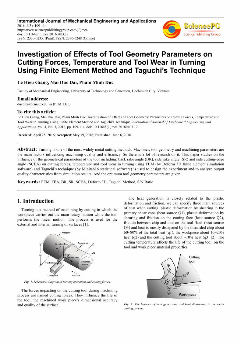
The heat generation is closely related to the plastic
deformation and friction, we can specify three main sources
of heat when cutting, plastic deformation by shearing in the
primary shear zone (heat source Q1), plastic deformation by
shearing and friction on the cutting face (heat source Q2),
friction between chip and tool on the tool flank (heat source
Q3) and heat is mostly dissipated by the discarded chip about
60~80% of the total heat (q1), the workpiece about 10~20%
heat (q2) and the cutting tool about ~10% heat (q3) [2]. The
cutting temperature affects the life of the cutting tool, on the
tool and work piece material properties.
Fig. 2. The balance of heat generation and heat dissipation in the metal
cutting process.

110 Le Hieu Giang et al.: Investigation of Effects of Tool Geometry Parameters on Cutting Forces, Temperature and Tool
Wear in Turning Using Finite Element Method and Taguchi’s Technique
The wear of tool influences the machined work piece’s
dimensional accuracy and quality of the surface.
Therefore, the main objective of this research is the study of
the influence of the geometric parameters of the tool on the
cutting forces, temperature and tool wear in turning to improve
the tool geometry parameters. The input quality characteristics
of simulation analysis are shown in the tables below.
The workpiece material used for the metal cutting
simulation is AISI 1045 steel, a medium carbon, medium
tensile steel. It has very good machinability, reasonable
weldability. Typical engineering applications of AISI 1045
steel are as gears, shafts, axles, bolts, studs and machine parts.
Table 1. The tool geometry parameters and its levels.
Tool geometry parameters Level 1 Level 2 Level 3 Level 4
SCEA (°) 0 15 30 45
BR (°) -5 -7 -9 -11
SR (°) -5 -7 -9 -11
Table 2. The machining parameters.
Cutting speed(m/min) Feed rate(mm/rev) Depth of cut(mm)
103.2 0.16 2
Table 3. Mechanical and thermal properties of AISI 1045 carbon steel.
Density
(g.cm-3)
Poisson
ratio
Elasticity
(GPa)
Thermal conductivity
(W.m-1oK-1)
Specific heat
(J.kg-1.K-1)
Thermal expansion
(µm.m-1 K-1)
Hardness
(HB)
7.87 0.29 212 41.7 450 11.9 170
The material for cutting tool insert is uncoated cemented carbide, which has a good hot hardness, wear resistance and
strength for metal cutting operations.
Table 4. Mechanical and thermal properties of tungsten carbide insert.
Density
(g.cm-3)
Poisson
ratio
Elasticity
(GPa)
Thermal conductivity
(W.m-1K-1)
Specific heat
(J.kg-1.K-1)
Thermal expansion
(µm.m-1°C -1)
Hardness
(HB)
15 0.25 650 59 15 5 1433
2. Finite Element Method (FEM)
In recent years, the finite element method (FEM) is the
most popular method of simulation and finite element
analysis (FEA) has become the main tool for simulating
metal cutting processes. Because FEA requires less time and
cost as well as it provides detailed results such as the cutting
force, stress, strain, strain rate, tool wear and temperature of
the metal cutting process. There are some popular finite
element softwares for simulation of cutting process such as
Ansys, Deform 3D, Abaqus, etc. In this paper, the FEM
software Deform 3D with updated Lagrangian formulation
combined with automatic remeshing techniques [3] is used to
simulate turning process. In this approach, there is no need
for a chip separation criterion, making it is highly effective in
simulating metal cutting process [4]. The important factor in
the metal cutting simulation is modelling the process
properly in order to obtain true results. This software
includes several key models as: the material constitutive
model; tool wear model; friction model and thermal model.
And the most important one is the material constitutive
model. The metal cutting process is the large strain, high
strain rate and high temperature process. And Johnson-Cook
material model (1) is favored as well in studies of problems
like that.
�� = [A + B( �) ][1 + Cln � ������ ��][1 − � ����
�������
] (1)
Where � � = equivalent stress, � = equivalent plastic strain,
� � = equivalent plastic strain rate, � � � = initial reference plastic
strain rate, T = operating temperature, To = room
temperature, Tm = the melting temperature, A = initial yield
stress, B = strain hardening coefficient, n = strain hardening
index, C = strain rate dependency coefficient, and m =
thermal softening index.
Tool wear calculation with Usui model as shown in eq (2):
� = !" #(�$%)&' (2)
Where p = interface pressure, V = sliding velocity, T =
interface temperature (in degrees absolute), dt = time
increment, a, b = experimentally calibrated coefficients.
Table 5. Boundary conditions.
Shear friction
coeff.
Interface heat
transfer coeff. Convection coeff.
Environment
temperature
0.5 100 (N/smm°C) 0.02 20°C
The tool is meshed with 45.000 tetrahedron elements,
while the number of elements in the workpiece is kept at
20 % of feed rate. Simulation steps are 16000 and data are
saved every 25 steps.
3. Taguchi Method
The Taguchi method is a powerful tool to design
optimization for quality. This method uses a special design of
orthogonal array (OA) to study the quality characteristics
with a minimal number of experiments [5], and signal-to-
noise ratios (S/N) are used to evaluate the performance
characteristics.

International Journal of Mechanical Engineering and Applications 2016; 4(3): 109-114 111
Minimum experiments = 1+ (#factors x (#levels-1)) (3)
For Taguchi method, there are 3 types of the signal-to-
noise ratio.
Smaller-is-the-better: (/* = −10,�- �. ∑ 012 13. � (4)
Larger-is-the-better: (/* = −10,�- 4. ∑ .
567 13. 8 (5)
Nominal-is-the-best: (/* = 10,�- 4 5�9:7
8 (6)
The Taguchi method applied in this study, the input
parameters includes 3 factors: back rake angle (BR), side
rake angle (SR) and side cutting-edge angle (SCEA) with 4
levels.
Minimum experiments = 1 + [(L − 1) P] = 1 + [(4 − 1)3] = 10 ≈ L16.
And the output parameters of the simulation analysis are
cutting forces, temperature and tool wear, so we will select
the first criterion (smaller is the better).
Table 6. The L16 inner orthogonal array.
Trial no Side cutting- edge angle (SCEA) (°) Back rake angle (BR) (°) Side rake angle (SR) (°)
1 0 -5 -5
2 0 -7 -7
3 0 -9 -9
4 0 -11 -11
5 15 -5 -7
6 15 -7 -5
7 15 -9 -11
8 15 -11 -9
9 30 -5 -9
10 30 -7 -11
11 30 -9 -5
12 30 -11 -7
13 45 -5 -11
14 45 -7 -9
15 45 -9 -7
16 45 -11 -5
This setup allows the testing of all 3 factors with 4 levels without having to run 64 (=43)
4. Simulation Results and Discussion
4.1. Numerical Results
Based on the L16 inner orthogonal array, finite element analysis (FEA) is conducted to investigate effects of tool geometry
parameters: SCEA, BR and SR on cutting forces, temperature and tool wear in turning. The results are shown in Table 7.
Table 7. The output quality characteristics of simulation analysis.
Trial no Tool-chip interface temp (°C) Wear depth (mm) Cutting forces (N)
Fx Fy Fz F resultant
1 682 1.15E-7 173 960 168 989
2 690 1.19E-7 209 971 206 1014
3 737 1.46E-7 314 1304 314 1377
4 772 1.23E-7 364 1302 389 1406
5 686 1.18E-7 209 1049 233 1094
6 695 1.34E-7 184 1104 271 1151
7 729 1.35E-7 329 1217 390 1319
8 720 1.35E-7 288 1192 409 1292
9 679 1.11E-7 171 802 218 848
10 700 1.24E-7 224 954 339 1036
11 674 1.13E-7 127 792 236 836
12 696 1.13E-7 159 826 295 891
13 679 0.93E-7 150 751 254 806
14 694 1.07E-7 139 832 297 894
15 685 0.96E-7 120 796 273 824
16 683 0.95E-7 101 745 268 798
Based on the results in Table 7, when the side rake angle
and the back rake angle decrease from -5° to -11°, the
temperature on the tool-chip interface and the cutting force
increase from 682°C to 772°C and from 989 N to 1406 N,
respectively. This is fully agreeable with theory and the
previous studies by Stephenson et al. [6], Gunay et al. [7],

112 Le Hieu Giang et al.: Investigation of Effects of Tool Geometry Parameters on Cutting Forces, Temperature and Tool
Wear in Turning Using Finite Element Method and Taguchi’s Technique
Haci Saglam et al. [8], Cerenitti [9] and Sabri [10]. Because
the rake angles decrease, it causes more the contact area and
friction between the rake face and the chip as well as the
chips flow more difficult across the rake face (chip jamming)
as the rake angles decrease, then it causes more the
temperature at the tool-chip interface during cutting process
and the cutting force is bigger.
Using Minitab software to analysis the results from the
simulation, showed in Table 8 and Fig. 3.
Table 8. The combined S/N ratio of the output quality characteristics.
Trial no Tool-chip interface temp (°C) Wear depth (mm) Cutting forces (N) Combined S/N ratio
Fx Fy Fz F resultant
1 682 1.15E-7 173 960 168 989 -56.7731
2 690 1.19E-7 209 971 206 1014 -56.9624
3 737 1.46E-7 314 1304 314 1377 -59.1014
4 772 1.23E-7 364 1302 389 1406 -59.3329
5 686 1.18E-7 209 1049 233 1094 -57.4493
6 695 1.34E-7 184 1104 271 1151 -57.8004
7 729 1.35E-7 329 1217 390 1319 -58.7913
8 720 1.35E-7 288 1192 409 1292 -58.6286
9 679 1.11E-7 171 802 218 848 -55.9481
10 700 1.24E-7 224 954 339 1036 -57.1692
11 674 1.13E-7 127 792 236 836 -55.8477
12 696 1.13E-7 159 826 295 891 -56.2951
13 679 0.93E-7 150 751 254 806 -55.6847
14 694 1.07E-7 139 832 297 894 -56.3038
15 685 0.96E-7 120 796 273 824 -55.8186
16 683 0.95E-7 101 745 268 798 -55.6557
Fig. 3. Main effects plot for S/N ratios.
From Table 8 and Fig. 3, the optimum tool geometry parameters are SCEA=45°, BR= -5° and SR= -5o.
Furthermore, an analysis of variance (ANOVA) is performed to see which process parameters are significant [11]. The
ANOVA is given in Table 9.
Table 9. ANOVA for S/N ratio.
Source DF Seq SS Adj SS Adj MS F P % Contribution
SCEA 3 16.6686 16.6686 5.5562 29.70 0.001 67.11
BR 3 2.5333 2.5333 0.8444 4.51 0.056 10.20
SR 3 4.5150 4.5150 1.5050 8.04 0.016 18.18
Residual error 6 1.1226 1.1226 0.1871
Total 15 24.8396

International Journal of Mechanical Engineering and Applications 2016; 4(3): 109-114 113
From the ANOVA: SCEA has the largest effect on the output quality characteristics with 67.11%, SR with 18.18% and BR
has the smallest effect on the output quality characteristics with 10.20%.
With the identified optimum tool geometry parameters, a validation simulation analysis is performed.
Table 10. The output quality characteristics of simulation analysis with the identified optimum tool geometry parameter.
Trial no Tool-chip interface temp (°C) Wear depth (mm) Cutting forces (N)
Fx Fy Fz F resultant
1 655 0.86E-7 86 696 176 723
Fig. 4. The generated temperature in machining process.
Fig. 5. The wear of tool in machining process.
a. Feed force
b. Main cutting force
c. Radial force
Fig. 6. The generated cutting forces during the cutting simulation analysis.
4.2. Comparison Between Experimental and Numerical
Results
The simulation result obtained were validated by
comparison with appropriate tool-work thermocouple
measurements provided in Ref [12]. The cutting process
simulation parameters were taken same conditions used in the
reference experiment, i.e. cutting speeds of 103.2, 206.4 and
330 m/min, feed rate of 0.16 mm/rev, depth of cut of 2 mm,
AISI 1045 steel workpiece and tungsten carbide tool material
as well as the tool’s geometrical features. The comparison
between measured and computed values of the average tool–
chip interface temperature is presented in Fig. 7 [13].

114 Le Hieu Giang et al.: Investigation of Effects of Tool Geometry Parameters on Cutting Forces, Temperature and Tool
Wear in Turning Using Finite Element Method and Taguchi’s Technique
Fig. 7. Comparison between measured and computed tool-chip interface
temperatures.
It shows good agreement between experimental and
simulation values for the three selected cutting speeds with
the percentage error of 2.3, 5.3, and 3.6 % for speeds 103.2,
206.4, and 330 m/min respectively.
5. Conclusion
From the simulation results, it is concluded that:
When the side rake and back rake angles decrease from -5°
to -11°, the temperature in the machining process and the
cutting force increase from 682°C to 772°C and from 989 N
to 1406 N, respectively.
The identified optimum tool geometry parameters are
SCEA=45°, BR= -5° and SR= -5°. The SCEA has the largest
effect on the output quality characteristics with 67.11%, SR
with 18.18% and BR has the smallest effect on the output
quality characteristics with 10.20%.
All of the results are agreeable with theory and some
simulations and experiments in references.
References
[1] Hassan Abdel, Gawad El-Hofy. Fundamentals of machining processes: conventional and nonconventional processes. CRC press, 2006.
[2] Valery Marinov. Manufacturing processes for metal products. Kendall Hunt Publishing Company, 2010.
[3] T. Ozel, I. Llanos, J. Soriano And P. J. Arrazola. 3D finite element modelling of chip formation process for machining inconel 718: comparison of fe software predictions. Machining Science and Technology. 15, (2011), 21-46.
[4] Tugrul O¨ zel. The influence of friction models on finite element simulations of machining. International Journal of Machine Tools & Manufacture, 46 (2006) 518–530.
[5] N. Senthilkumar, T. Tamizharasan. Effect of tool geometry in turning aisi 1045 steel: experimental investigation and fem analysis. Arab J Sci Eng (2014) 39, 4963–4975.
[6] Stephenson, A. A., & Agapiou, J. S. Metal cutting theory and practice. Marcel Dekker. Inc, New York, 1996.
[7] Gunay, M., Korkut, I. & Seker, U. Experimental investigation of the effect of cutting tool rake angle on main cutting force. Journal of Material Processing Technology, 166, 2005, 44–49.
[8] Haci Saglam, Faruk Unsacar, Suleyman Yaldiz. Investigation of the effect of rake angle and approaching angle on main cutting force and tool tip temperature. International Journal of Machine Tools & Manufacture, 46 (2006), 132–141.
[9] Cerenitti, E., Fallbohmer, P. & Altan, T. Application of 2d fem to chip formation in orthogonal cutting. Journal of Materials Processing Technology, 59, 1996, 169–180.
[10] Sabri Ozturk. Slip-line metal cutting model with negative rake angle, Journal of the Brazilian Society of Mechanical Sciences and Engineering, vol.34 (2012).
[11] W. H. Yang, Y. S. Tarng. Design optimization of cutting parameters for turning operations based on the Taguchi method. Journal of Material Processing Technology, 84(1998) 122-129.
[12] W. Grzesik, P. Nies³ony. FEM–based thermal modelling of the cutting process using power law temperature dependent concept. International Scientific Journal, Volume 29 Issue 2February 2008, 105-108.
[13] W. Grzesik, M. Bartoszuk, P. Nieslony. Finite element modelling of temperature distribution in the cutting zone in turning processes with differently coated tools. Journal of Materials Processing Technology 164–165 (2005), 1204–1211.
[14] Corina Constantin, Sorin Mihai Croitoru, George Constantin, Claudiu Florinel Bisu. 3D fem analysis of cutting processes. Advances In Visualization, Imaging And Simulation.
[15] Shufeng Sun1,A, Pingping Wang1,B, Xin Wu1,C, Sen Lin1,D. NC turning process parameters optimization based on simulation software. Applied Mechanics And Materials Vols. 271-272 (2013), 452-456.
[16] Ruan Hongyan1, A, Yan Hua1, Lu Shubin1, Liu Huixia1, Wang Xiao1. The investigation of tool wear in metal machiningusing finite element method. Key Engineering Materials Vols 407-408 (2009), 395-399.