Embed Size (px)
Citation preview
INVESTIGATION OF CORROSION AND OTHER DETERIORATION EFFECTS IN HIGHWAY BRIDGE COMPONENTS USING
NONDESTRUCTIVE TESTING TECHNOLOGY OF ACOUSTIC EMISSION
Final Report
Vadivel Jagasivamani
Research Assistant Professor School of Engineering and Technology
Hampton University Hampton, VA 23668
757-727-5583 [email protected]
March 2014
Eastern Seaboard Intermodal Transportation Applications Center (ESITAC)
Hampton University, Hampton, VA 23668
1
DISCLAIMER The contents of this report reflect the views of the authors, who are responsible for the facts and the accuracy of the information presented herein. This document is disseminated under the sponsorship of the Department of Transportation University Transportation Centers Program, in the interest of information exchange. The U.S. Government assumes no liability for the contents or use thereof.
2
INVESTIGATION OF CORROSION AND OTHER DETERIORATION EFFECTS IN HIGHWAY BRIDGE COMPONENTS USING
NONDESTRUCTIVE TESTING TECHNOLOGY OF ACOUSTIC EMISSION
Table of Contents
ACKNOWLEDGEMENT ........................................................................................................................................ 2 EXECUTIVE SUMMARY ....................................................................................................................................... 3 INTRODUCTION.................................................................................................................................................... 4 OBJECTIVES ........................................................................................................................................................... 5 LITERATURE SURVEY......................................................................................................................................... 6 MEASUREMENT OF AE .............................................................................................................................................................7 RISE TIME....................................................................................................................................................................................8 ACOUSTIC ENERGY.....................................................................................................................................................................8 RESISTIVITY TESTING ...............................................................................................................................................................8 SELECTION OF STEEL BARS FOR REINFORCEMENT........................................................................................................... 10
REFERENCES: ......................................................................................................................................................10 MEASUREMENT EFFORTS ...............................................................................................................................12 BRIDGE UNDER TEST.............................................................................................................................................................. 12 AE INSTRUMENTATION ......................................................................................................................................................... 12 SENSOR INSTALLATION ......................................................................................................................................................... 13 RESISTIVITY MEASUREMENT................................................................................................................................................ 14
RESULTS AND DISCUSSION.............................................................................................................................14 AE MEASUREMENT................................................................................................................................................................. 14 RESISTIVITY MEASUREMENT................................................................................................................................................ 14
SUMMARY.............................................................................................................................................................18
ACKNOWLEDGEMENT The author acknowledges the support extended by VDOT’s District Structure and Bridge Engineering Department and its research arm, the Virginia Center of Transportation Innovation and Research (VCTIR) to investigate corrosion and other damages in concrete columns of Highway Bridge using acoustic emission method. The author is grateful to the technical advice and support given by Dr. Stephen R. Sharp, Research scientist, VCTIR and Mr. Shannon M. Ternes, District Structure & Bridge Safety Engineer, VDOT, Hampton Roads District, in carrying out the work. Extended support provided by Hampton University’s Eastern Seaboard Intermodal Transportation Applications Center (ESITAC) is gratefully acknowledged.
3
INVESTIGATION OF CORROSION AND OTHER DETERIORATION EFFECTS IN HIGHWAY BRIDGE COMPONENTS USING
NONDESTRUCTIVE TESTING TECHNOLOGY OF ACOUSTIC EMISSION
Executive Summary Virginia Department of Transportation (VDOT) carries out periodical evaluation of the damages and deterioration in aging highway bridges and performs maintenance, rehabilitation and repair (MR&R) to prolong their useful life. The process of identifying the deterioration, locating the defects and identifying the means of preventing further damages is time consuming and in most cases the process is of subjective in nature. There are possibilities of human error in assessing the status of such damages. Better methods of testing the bridges are needed to perform these operations efficiently and effectively. In-service diagnostic methods for the evaluation of corrosion steel-reinforced concrete structures are useful to reduce the maintenance costs and to ensure safety. Acoustic Emission (AE) monitoring is one of the most promising methods to monitor the deterioration of the structure. There are several NDT methods to complement AE monitoring. It is essential to support the results of AE tests, using other techniques too, to improve the reliability of test results. Resistivity measurement on the surface of concrete is identified as one of the useful methods to improve the reliability of testing for corrosion. This research effort focuses on testing Highway Bridge in the Denbigh Blvd., crossing I-64, for studies of corrosion related damages in the concrete columns, using AE method. With a permanent installation of AE monitoring facility the integrity of the structural members can be monitored continuously, as the damages take place, thereby maintenance work can be carried out in time. In addition to AE method, resistivity measurements in the columns have been carried out to evaluate the usefulness of such tests.
4
INVESTIGATION OF CORROSION AND OTHER DETERIORATION EFFECTS IN HIGHWAY BRIDGE COMPONENTS USING
NONDESTRUCTIVE TESTING TECHNOLOGY OF ACOUSTIC EMISSION
Introduction Highway Bridges are a vital part of transportation system. Steel and concrete are used as important structural materials in the construction of bridges. The annual cost of corrosion damages in Transportation Industry amounts to $29.7 billion out of which the damage in highway bridges amount to $ 8.3 billions, in 2002 (1). Virginia Department of Transportation (VDOT) carries out periodical evaluation of the damages and deterioration in highway bridges and carries out maintenance, rehabilitation and repair (MR&R) to ensure safety and to prolong their useful life. Visual inspection is the most commonly used method of detecting corrosion. Electrochemical measurements and resistivity method are sometimes used to determine the vulnerability of concrete structures to corrosion. The process of identifying the deterioration is time consuming and in most cases the process is of subjective in nature. There are possibilities of human error in assessing the status of such damages. Better methods of testing the bridges are needed to perform these operations efficiently and effectively. In-service diagnosis methods for corrosion damage evaluation of steel-reinforced concrete structures in bridges are useful to reduce the maintenance costs and to ensure safety and reliability.
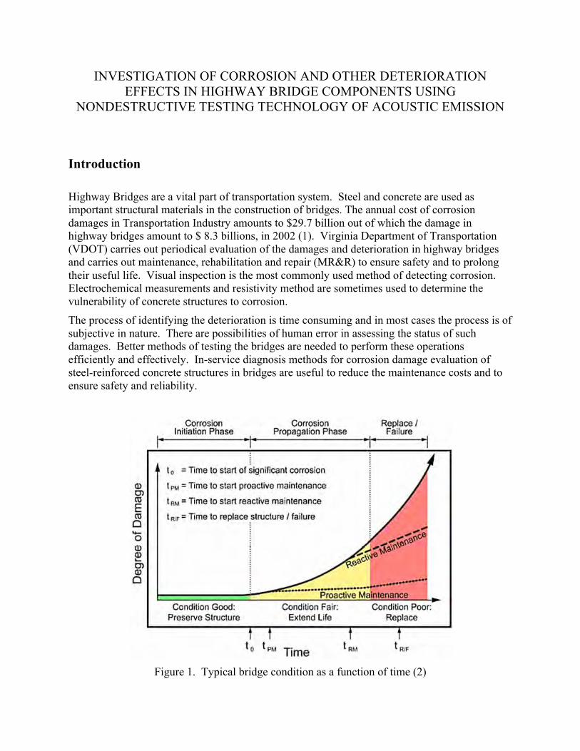
Figure 1. Typical bridge condition as a function of time (2)
5
The process of corrosion in concrete structures involves several stages. Acoustic Emission (AE) monitoring is one of the most promising methods of monitoring the deterioration of the structure at different stages of deterioration. AE technique can be adopted to forewarn the maintenance team and to carryout repair work in a timely manner, thus saving the cost of repair and in prolonging the life of structures. Figure 1 shows the different stages of corrosion damages and indicates the importance of attending the maintenance at early stages (2).
The most appropriate NDT technique suitable for testing vary among bridges, since not all bridges are designed and constructed in the same way. In most cases it may be essential to optimize the NDT technique to meet the requirements of each bridge structure. R&D efforts that continually evaluate the effectiveness of different NDT techniques, in collaboration with the maintenance group is very useful in developing and implementing the optimum methods of ensuring the integrity of bridge structures.
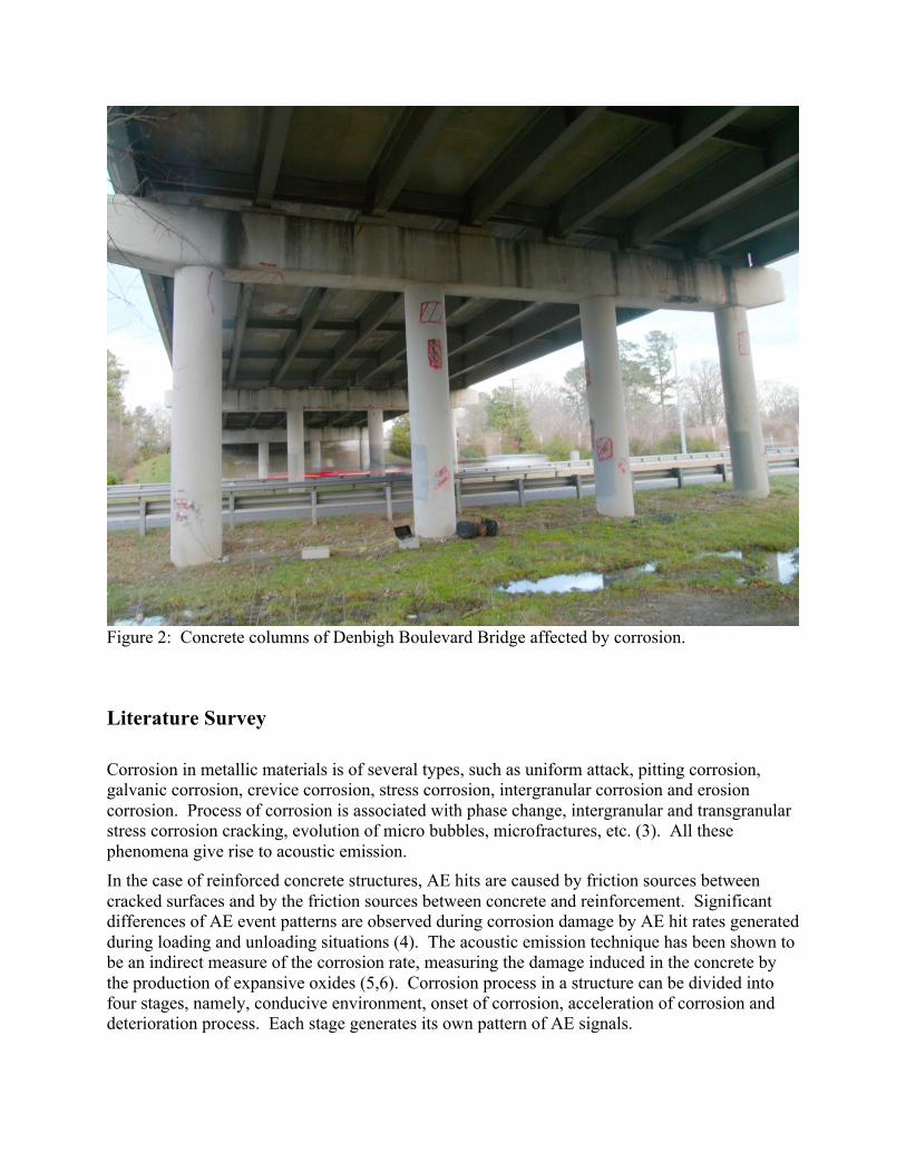
Objectives This research effort focuses on testing Highway Bridge in the Denbigh Boulevard, crossing I-64, for studies of corrosion related damages in the concrete columns, using AE method. AE signals arise from various sources, such as ambient noise and vibrations, vehicle and train movements, propagation of crack and corrosion activities. It becomes difficult to eliminate the unwanted parts of the signals and to identify the signals that arise from corrosion activities. The corrosion damages in the columns are clearly visible. Also, fine hairline cracks on the concrete surface are seen in many parts of the concrete structure. AE method of detecting the onset of corrosion and propagation of damage is useful, since it is possible to reveal the onset of corrosion activities at very early stages that provide enough time to carry out remedial measures. In the current research work, the usefulness of AE technology in identifying the corrosion activities at the midst of several disturbing unrelated emissions of acoustic signals is being studied. In addition to the AE method, usefulness of resistivity measurements in the columns is also considered, to predict the possibilities of the occurrence of corrosion in reinforced concrete structures, exposed to severe environments. Figure 2 shows the picture of concrete columns affected by corrosion in the reinforced steels.
6
Figure 2: Concrete columns of Denbigh Boulevard Bridge affected by corrosion.
Literature Survey Corrosion in metallic materials is of several types, such as uniform attack, pitting corrosion, galvanic corrosion, crevice corrosion, stress corrosion, intergranular corrosion and erosion corrosion. Process of corrosion is associated with phase change, intergranular and transgranular stress corrosion cracking, evolution of micro bubbles, microfractures, etc. (3). All these phenomena give rise to acoustic emission. In the case of reinforced concrete structures, AE hits are caused by friction sources between cracked surfaces and by the friction sources between concrete and reinforcement. Significant differences of AE event patterns are observed during corrosion damage by AE hit rates generated during loading and unloading situations (4). The acoustic emission technique has been shown to be an indirect measure of the corrosion rate, measuring the damage induced in the concrete by the production of expansive oxides (5,6). Corrosion process in a structure can be divided into four stages, namely, conducive environment, onset of corrosion, acceleration of corrosion and deterioration process. Each stage generates its own pattern of AE signals.
7
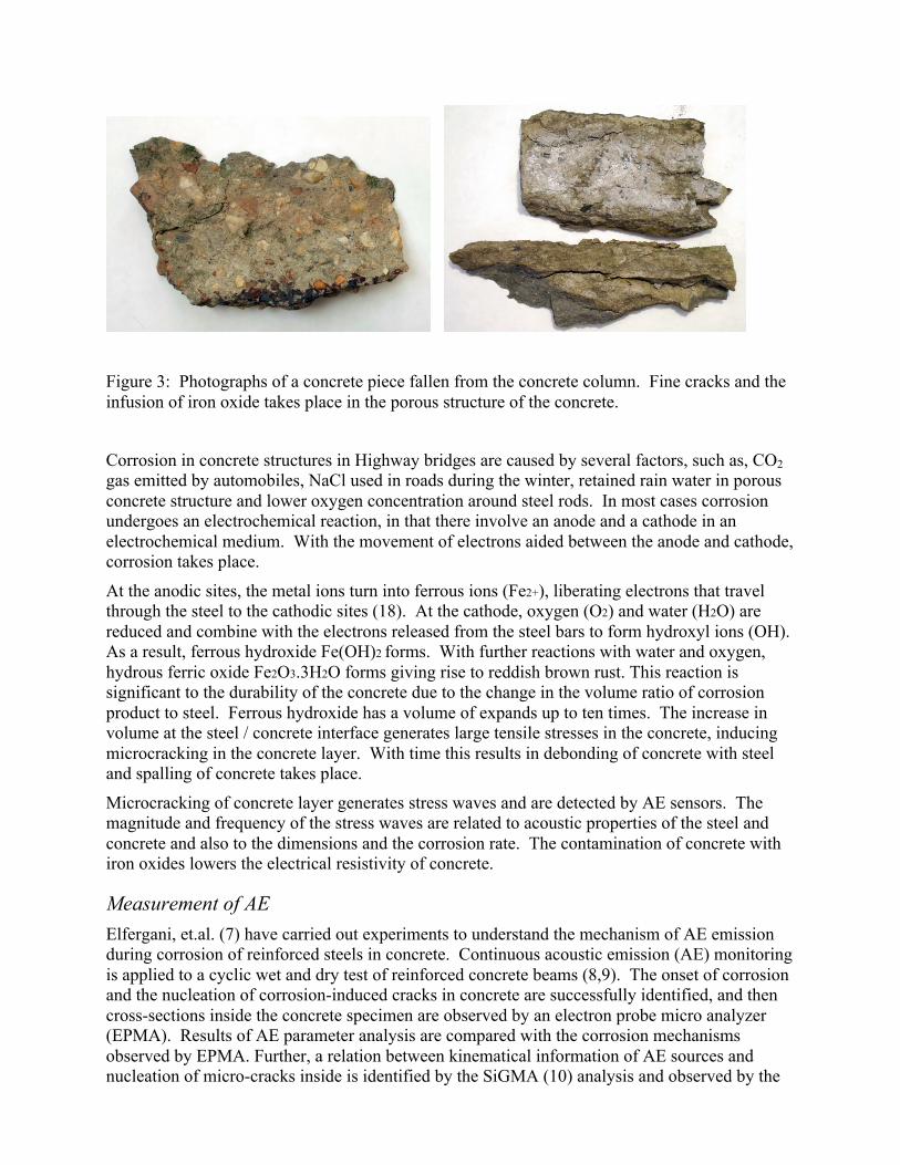
Figure 3: Photographs of a concrete piece fallen from the concrete column. Fine cracks and the infusion of iron oxide takes place in the porous structure of the concrete.
Corrosion in concrete structures in Highway bridges are caused by several factors, such as, CO2 gas emitted by automobiles, NaCl used in roads during the winter, retained rain water in porous concrete structure and lower oxygen concentration around steel rods. In most cases corrosion undergoes an electrochemical reaction, in that there involve an anode and a cathode in an electrochemical medium. With the movement of electrons aided between the anode and cathode, corrosion takes place.
At the anodic sites, the metal ions turn into ferrous ions (Fe2+), liberating electrons that travel through the steel to the cathodic sites (18). At the cathode, oxygen (O2) and water (H2O) are reduced and combine with the electrons released from the steel bars to form hydroxyl ions (OH). As a result, ferrous hydroxide Fe(OH)2 forms. With further reactions with water and oxygen, hydrous ferric oxide Fe2O3.3H2O forms giving rise to reddish brown rust. This reaction is significant to the durability of the concrete due to the change in the volume ratio of corrosion product to steel. Ferrous hydroxide has a volume of expands up to ten times. The increase in volume at the steel / concrete interface generates large tensile stresses in the concrete, inducing microcracking in the concrete layer. With time this results in debonding of concrete with steel and spalling of concrete takes place.
Microcracking of concrete layer generates stress waves and are detected by AE sensors. The magnitude and frequency of the stress waves are related to acoustic properties of the steel and concrete and also to the dimensions and the corrosion rate. The contamination of concrete with iron oxides lowers the electrical resistivity of concrete.
Measurement of AE Elfergani, et.al. (7) have carried out experiments to understand the mechanism of AE emission during corrosion of reinforced steels in concrete. Continuous acoustic emission (AE) monitoring is applied to a cyclic wet and dry test of reinforced concrete beams (8,9). The onset of corrosion and the nucleation of corrosion-induced cracks in concrete are successfully identified, and then cross-sections inside the concrete specimen are observed by an electron probe micro analyzer (EPMA). Results of AE parameter analysis are compared with the corrosion mechanisms observed by EPMA. Further, a relation between kinematical information of AE sources and nucleation of micro-cracks inside is identified by the SiGMA (10) analysis and observed by the
8
stereomicroscope. From these results, AE is found to be a promising technique to quantitatively evaluate the corrosion process in concrete due to expansion of corrosion products, at an early stage, is demonstrated. AE method has been used successfully in testing for corrosion in tank bottoms. A digital AE system, mDiSP with a 4-channel board (Physical Acoustics Corporation Ltd.) and 150 kHz AE sensor of a narrow band was used for acquisition of AE signals. An AE sensor was set on the top surface of the specimen. The AE propagation distance is kept short and the attenuation of AE waves during propagation are kept to a minimum. A 150 kHz sensor provides high receiving sensitivity in the range of 30 - 200 kHz. Rate of hits was used along with peak frequency of the FFT and RMS value were analyzed to monitor the corrosion (11).
Regarding the detection of corrosion in concrete columns, there are additional constraints. There is a need to exclude the emissions due to other external factors. Characteristics of the acoustic emission signals produced during the corrosion in reinforced concrete have been studied using waveform parameter analysis. Energy analysis and the frequency spectrum analysis for each waveform are found to be more significant of AE emissions during the corrosion activity (12).
Rise time Jones and Friesel, (13), have reported that in monitoring for the stress-corrosion cracking, use of rise time along with event rate, and amplitude could be used to discriminate among valid and invalid events. Ohtsu et.al (14) have reported that the measurement of rise time/amplitude (RA) and average frequency was successfully adopted to monitor tensile cracks generated due to expansion of corrosive products.
Acoustic energy AE signals recorded over a 24-h period were converted into energy per second (15). Even though the parameter was an indicative of the corrosion activity, the AE energy per hour between successive days was found to be irregular. At low corrosion rates the duration of monitoring will significantly influence the accuracy of detection. Due to the irregular nature of the emission, only a couple of high-energy AE hits are required to distort the data collected within a 24-h period. The total AE energy recorded over a finite period can only indicate an approximate range of corrosion activity. Due to the low corrosion rate, only a relatively small number of processes occur within each 24-h period, consequently the variations in energy that occur naturally between each microfracture are not averaged out hence distorting the cumulative values. It is evident that the temperature and hence time of year, has apparently little influence on the ability of AE to detect corrosion of steel in concrete. Whilst the maximum energy per second increases at higher temperatures there is no clear relationship between temperature and AE Energy.
Resistivity testing Concrete is a porous material that absorbs moisture; it allows the infusion of salt and carbon-di-oxide to takes place and the concrete structure becomes vulnerable to corrosion. Very porous
9
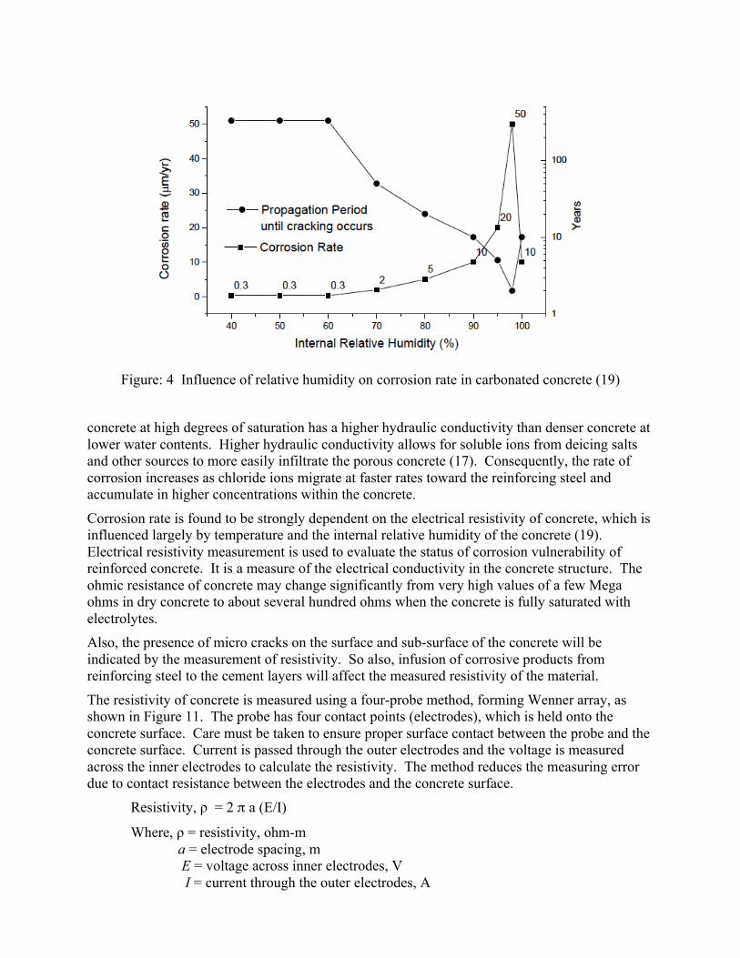
Figure: 4 Influence of relative humidity on corrosion rate in carbonated concrete (19)
concrete at high degrees of saturation has a higher hydraulic conductivity than denser concrete at lower water contents. Higher hydraulic conductivity allows for soluble ions from deicing salts and other sources to more easily infiltrate the porous concrete (17). Consequently, the rate of corrosion increases as chloride ions migrate at faster rates toward the reinforcing steel and accumulate in higher concentrations within the concrete.
Corrosion rate is found to be strongly dependent on the electrical resistivity of concrete, which is influenced largely by temperature and the internal relative humidity of the concrete (19). Electrical resistivity measurement is used to evaluate the status of corrosion vulnerability of reinforced concrete. It is a measure of the electrical conductivity in the concrete structure. The ohmic resistance of concrete may change significantly from very high values of a few Mega ohms in dry concrete to about several hundred ohms when the concrete is fully saturated with electrolytes. Also, the presence of micro cracks on the surface and sub-surface of the concrete will be indicated by the measurement of resistivity. So also, infusion of corrosive products from reinforcing steel to the cement layers will affect the measured resistivity of the material.
The resistivity of concrete is measured using a four-probe method, forming Wenner array, as shown in Figure 11. The probe has four contact points (electrodes), which is held onto the concrete surface. Care must be taken to ensure proper surface contact between the probe and the concrete surface. Current is passed through the outer electrodes and the voltage is measured across the inner electrodes to calculate the resistivity. The method reduces the measuring error due to contact resistance between the electrodes and the concrete surface.
Resistivity, ρ = 2 π a (E/I)
Where, ρ = resistivity, ohm-m a = electrode spacing, m E = voltage across inner electrodes, V I = current through the outer electrodes, A
10
Tests have been performed to investigate the resistivity of concrete in various conditions (9). Moist concrete typically shows a resistivity of 100 ohm-m, while oven-dried concrete exhibits a resistivity of 240 Mohm-m. Corrosion is almost certain to occur when resistivity measurements are less than 50 ohm-m. When resistivity measurements are between 50 and 120 ohm-m, corrosion is probable. The corrosion is unlikely to occur when resistivity measurements are in excess of 120 ohm-m. Corrosion is unlikely to occur when the resistivity exceeds 200 ohm-m. In addition, the study states that resistivity values between 50 and 100 ohm-m are needed to induce corrosion. Reduced resistivity may occur due to the absorbed electrolytes in the porous and moist concrete giving rise to an increased chloride ion concentration in the vicinity of the steel reinforcement.
While resistivity testing shows promise as an effective non-destructive method, there are no well-established standard to which measurements can be compared with. That is, although numerous suggestions have been reported, a consensus has not yet been reached regarding appropriate threshold resistivity values. Further research is needed to establish levels of resistivity that are reliably linked to corrosion potential and occurrence. Another deficiency is that the resistivity of concrete is most sensitive to near-surface conditions rather than to conditions in the vicinity of the reinforcement. Therefore, resistivity testing cannot be used as a primary testing method; it can, however, be used to provide information to supplement other testing methods.
Selection of steel bars for reinforcement Studies have been carried out to evaluate the use of various corrosion resistant steel bars in the construction of new bridges. Research study carried out by Stephen Sharp and Audrey Moruza of Virginia Transportation Research Council, evaluated the cost of placement of epoxy-coated reinforcing steel with corrosion-resistant reinforcing steel, MMFX2 (20). A field research using both these types of steels indicated that the epoxy coated steels demand special care in installation to avoid the damage of the coated surface during the transportation and installation and as a result corrosion-resistant steels are preferred. The corrosion resistant steels get passivated and are more immune to corrosion.
References:
1. “Corrosion costs and preventive strategies in the United Stages”, NACE International, Houston, TX, (www.nace.org), 2002
2. “Corrosion control plan for bridges”, white paper by NACE International, Houston, TX, (www.nace.org) 2012
3. Ono, K., “Acoustic emission in materials research – A review”, J. Acoustic emission, Vol 29, (2011), p 284-308
4. Yoon, D.J., and Park, P., “Assessment of crack activity by acoustic emission in concrete structures”, Asia-Pacific conference on NDT, Auckland, New Zealand, Nov 2006
5. Helier, C.J., “Handbook of Nondestructive Evaluation”, Chapter 10, McGraw-Hill, (2001)
6. Masatoshi Tanaka and Masayasu Ohtsu, “Monitoring Corrosion Damage in Reinforced Concrete by Acoustic Emission”, Graduate School of Science and Technology, Kumamoto University, JAPAN

11
7. Hisham A. Elfergani, Rhys Pullin, Karen M. Holford, “Damage assessment of corrosion in prestressed concrete by acoustic emission” Construction and Building Materials, Vol. 40, (2013), pp 925-933
8. Yuma Kawasaki, Tomoyo Wakuda, Tomoe Kobarai, Masayasu Ohtsu, “Corrosion mechanisms in reinforced concrete by acoustic emission”, Construction and Building Materials, Vol. 48, (2013), pp 1240-1247
9. Ritter, S. and Molander, A., “Corrosion monitoring in nuclear systems: research and applications”, European Federation of Corrosion Publications, No. 56, 2010
10. Mondoringin, M., et.al., “AE-SiGMA analysis in Brazilian Test of concrete”, Concrete Research Letters, Vol. 2 (3), Sep 2011
11. Sosoon Park, et. Al., “Development of AE Monitoring Method for Corrosion Damage of the Bottom Plate in Oil Storage Tank on the Neutral Sand under Loading”, Materials Transaction, Vol. 47, No. 4, (2006), pp 1240-1246
12. Dongsheng Li, Suikun Ding and Yuan Tao, "Acoustic emission monitor and evaluation method of steel corrosion damage for reinforced concrete", Proc. SPIE 7984, Health Monitoring of Structural and Biological Systems, April 2011
13. Jones, R.H. and Friesel, M.A., “Using acoustic emission to monitor stress-corrosion cracking, JOM, 1990, p 12.
14. Ohtsu, M., Tomoda, Y and Suzuki, T., “Damage evaluation and corrosion detection in concrete by acoustic emission”, Kumamoto University, Kumamoto, Japan.
15. Richard Lyons, Matthew Ing and Simon Austin, “Influence of diurnal and seasonal temperature variations on the detection of corrosion in reinforced concrete by acoustic emission”, Corrosion Science 47 (2005), pp 413–433
16. Breysse, D., “Nondestructive assessment of concrete structures: usual combinations of technique”, Non-destructive assessment of concrete structures: Reliability and limits of single and combined techniques, Springer 2012, p 1-16
17. Lataste, J.F., “Electrical Resistivity Measurement”, Non-destructive assessment of concrete structures: Reliability and limits of single and combined techniques, Springer 2012, p 77-85
18. Ing, M.J., et.al., “Risk-based investigation of steel reinforcement corrosion using theAeCORR technique”, Loughborough’s Institutional Repository, http://creativecommons.org/licenses/by-nc-nd/2.5/
19. Bentur, A., Diamond, S., Berke, N.S., “Steel corrosion in concrete”, London: Chapman & Hall. , 1997
20 Sharp, S.R., Moruza, A.K., “Field Comparison of the Installation and Cost of Placement of Epoxy-Coated and MMFX 2 Steel Deck Reinforcement: Establishing a Baseline for Future Deck Monitoring”, Final Report VTRC 09-R9, http://www.virginiadot.org/vtrc/main/online_reports/pdf/09-r9.pdf, (2009)
12
Measurement Efforts
Bridge under test Bridge on I-64 at the Denbigh Boulevard in Newport News, Virginia was chosen for studies in applying acoustic emission method to detect corrosion damage. This bridge (Virginia Structure No. 2222, Federal Structure ID 20727) built in 1965 and reconstructed in 1977 crosses over I-64 and the CSX Railway. Annual average daily traffic at Denbigh Blvd in 2010 is 28,000 vehicles per day; the truck percentage is 1%. The bridge is 864 feet long and 60 feet wide.
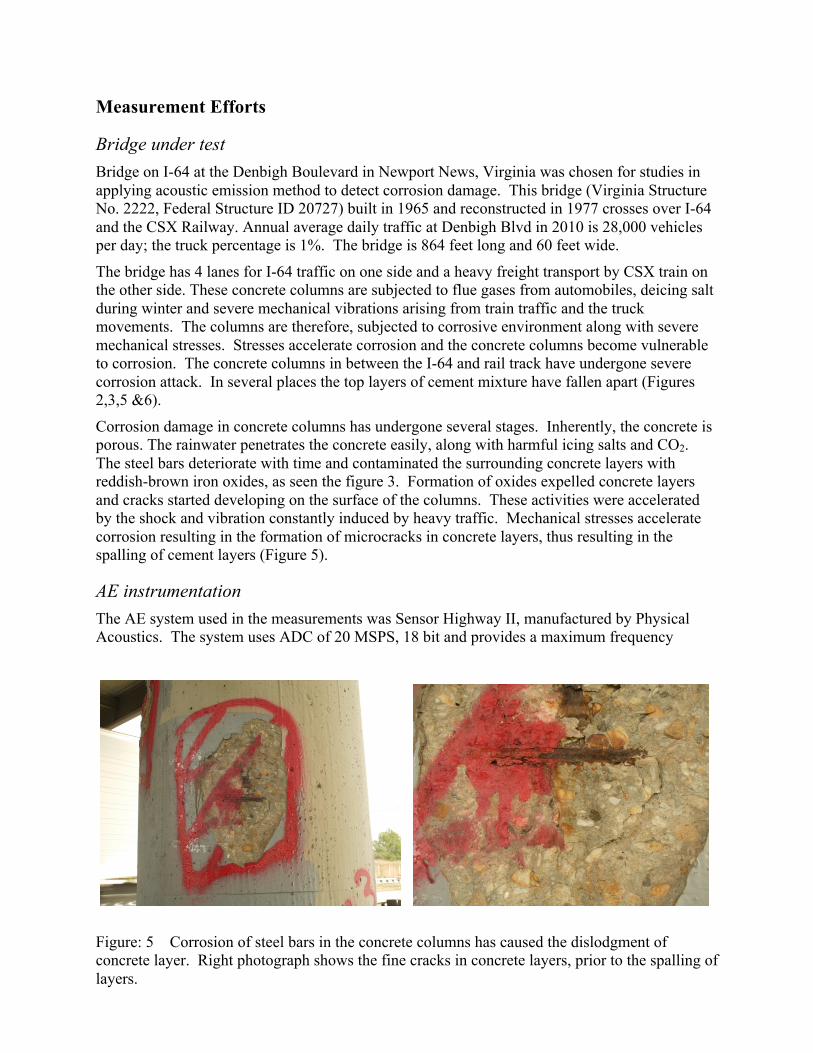
The bridge has 4 lanes for I-64 traffic on one side and a heavy freight transport by CSX train on the other side. These concrete columns are subjected to flue gases from automobiles, deicing salt during winter and severe mechanical vibrations arising from train traffic and the truck movements. The columns are therefore, subjected to corrosive environment along with severe mechanical stresses. Stresses accelerate corrosion and the concrete columns become vulnerable to corrosion. The concrete columns in between the I-64 and rail track have undergone severe corrosion attack. In several places the top layers of cement mixture have fallen apart (Figures 2,3,5 &6).
Corrosion damage in concrete columns has undergone several stages. Inherently, the concrete is porous. The rainwater penetrates the concrete easily, along with harmful icing salts and CO2. The steel bars deteriorate with time and contaminated the surrounding concrete layers with reddish-brown iron oxides, as seen the figure 3. Formation of oxides expelled concrete layers and cracks started developing on the surface of the columns. These activities were accelerated by the shock and vibration constantly induced by heavy traffic. Mechanical stresses accelerate corrosion resulting in the formation of microcracks in concrete layers, thus resulting in the spalling of cement layers (Figure 5).
AE instrumentation The AE system used in the measurements was Sensor Highway II, manufactured by Physical Acoustics. The system uses ADC of 20 MSPS, 18 bit and provides a maximum frequency
Figure: 5 Corrosion of steel bars in the concrete columns has caused the dislodgment of concrete layer. Right photograph shows the fine cracks in concrete layers, prior to the spalling of layers.
13
response of 1 MHz. AE instrument uses a threshold level setting to ignore the low level signals that are insignificant to the investigation. The selection of threshold level was set based onseveral factors, such as the sensitivity of the sensor system and the ambient noise. One of the main criteria for the selection of threshold level is the ambient noise. Raising the threshold level to a higher value will result in loosing some of the useful data. Most of the ambient noises are at lower frequencies of less than 50 kHz, so also unwanted signals induced by mechanical shocks and vibration are at lower frequencies. Selecting the sensors with frequency responses above 100 kHz will cut down most of the ambient noises. In these measurements AE probes manufactured by Physical Acoustics are employed. The current work used two kinds of probes, namely, resonance probes with built-in preamplifier of 26 dB and a center frequency of 150 kHz and wide band probes, model WD, with a frequency response ranging from 125 kHz to 1000 kHz. The WD probe is a differential sensor; a preamplifier with a gain setting of 40 dB was used with WD sensor.
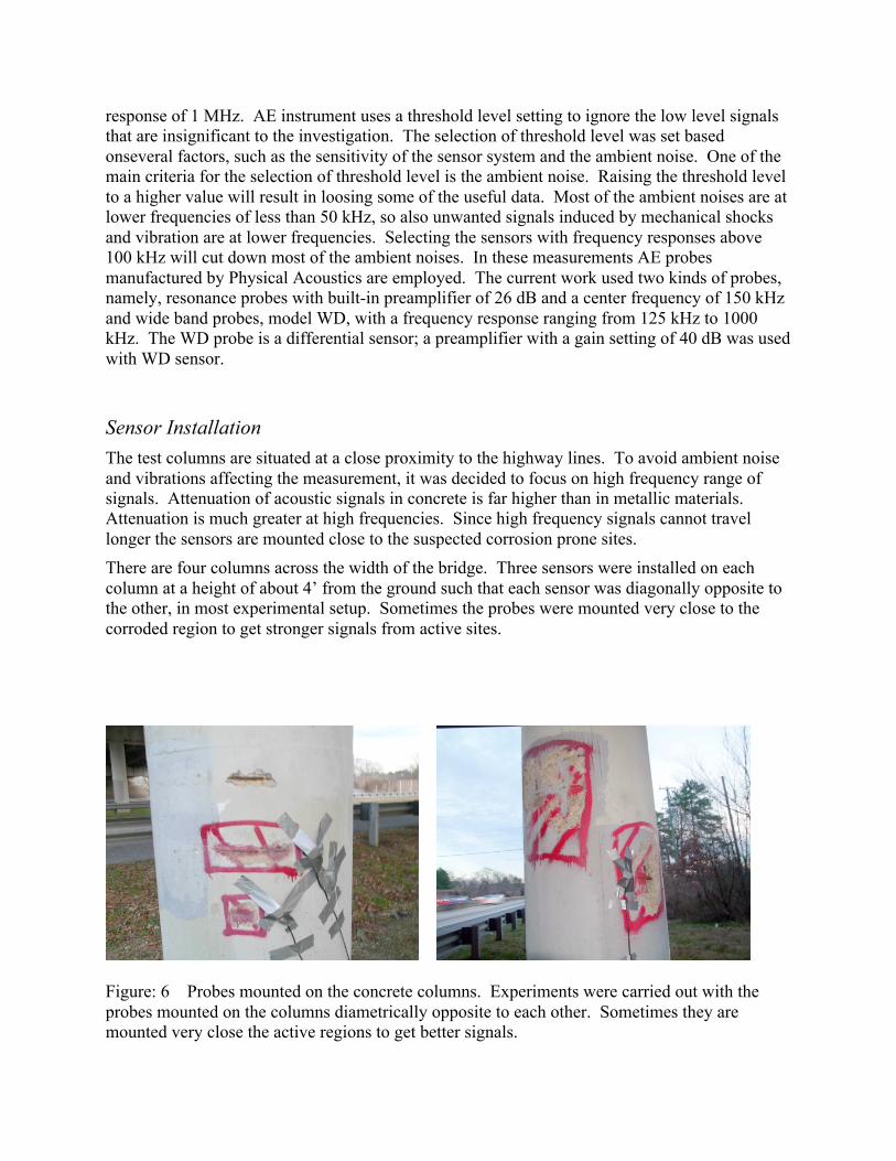
Sensor Installation The test columns are situated at a close proximity to the highway lines. To avoid ambient noise and vibrations affecting the measurement, it was decided to focus on high frequency range of signals. Attenuation of acoustic signals in concrete is far higher than in metallic materials. Attenuation is much greater at high frequencies. Since high frequency signals cannot travel longer the sensors are mounted close to the suspected corrosion prone sites. There are four columns across the width of the bridge. Three sensors were installed on each column at a height of about 4’ from the ground such that each sensor was diagonally opposite to the other, in most experimental setup. Sometimes the probes were mounted very close to the corroded region to get stronger signals from active sites.
Figure: 6 Probes mounted on the concrete columns. Experiments were carried out with the probes mounted on the columns diametrically opposite to each other. Sometimes they are mounted very close the active regions to get better signals.

14
Measurements were carried out over a period of 4 hours each day, under different environmental conditions. Acoustic emission is a transient phenomenon. Waveform of the transient signal can be availed from the measuring instrument. However, to carry out the interpretation easily, the waveform is quantized into various AE parameters such as Rise time, Counts, Energy, Duration, Amplitude, Average frequency, RMS voltage, etc. Depending upon the nature of the event that generates AE signal, it is necessary to correctly identify the most appropriate parameter to interpret the data meaningfully.
Resistivity measurement Resistivity measurements were carried out using Wenner array probe (Figure 11). The measurement carried out over a surface of the concrete is indicative of the moisture level and absorbed salt level in the concrete structure. However, the resistivity is highly dependent on the relative humidity and therefore measured values are not found to be consistent over a period of time. Also, the contact resistance between the measuring probe and the concrete surface poses a problem in achieving consistent measurement, especially when the surface is coated with protective coatings. With all these limitations, the resistivity measurement is a reliable indication of the vulnerability of structure to corrosion.
Results and discussion
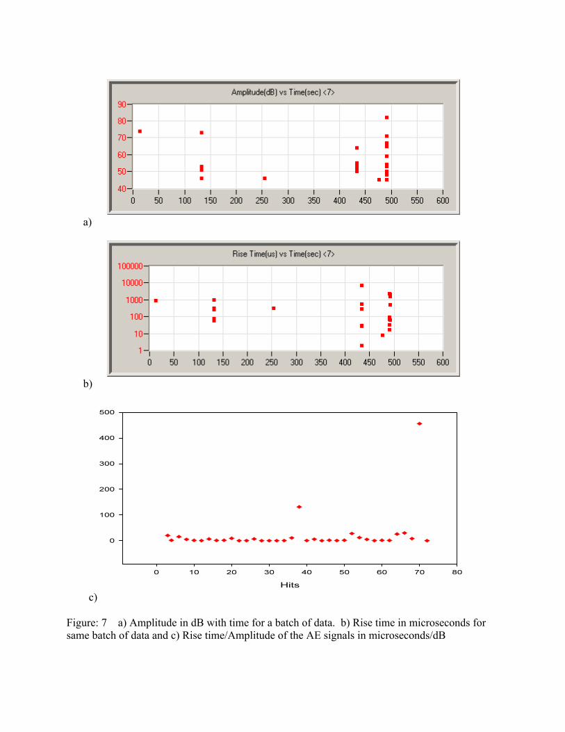
AE measurement In each of measurement task, hundreds of data points were collected. About 95% of the data points collected arose from unwanted sources, probably from the moving heavy vehicles. It becomes necessary to come up with a technique to exclude such unwanted signals. None of the AE parameters that were readily available from the measuring instrument was fully satisfactory, to exclude emission from mechanical vibrations and other noises. Parameters like amplitude and rise-time, exported from the instrument are shown in the figure 7a and 7b. Figure 7C shows the plot between RA and hits, where RA = Rise-time/amplitude. The graph identifies two data points distinctly to have higher RA value. On analyzing the waveforms of such data with higher amounts of RA, it is found that they represent typical signals expected from corrosion activities.
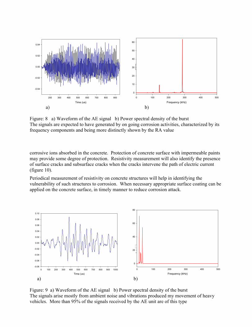
Figure 8a and 8b shows waveform and power spectral density from one of the data points with high RA value. Figure 9a and 9b shows waveform and power spectral density from one of the data points with a low RA value. Apparently the data point shown in figure 9 is due to severe vibration of the column caused by a moving heavy truck or a train. Thus there are two distinct characteristics of signals from corrosion sites, namely RA value and power spectral density. Thus, these two parameters can be applied to extract useful signals when AE technology is employed for long-term surveillance of corrosion activities in concrete structures.
Resistivity measurement Resistivity measurement on concrete surface is highly dependent on relative humidity in the atmosphere. With higher humidity levels, moisture penetrates concrete surface and exhibit lower resistivity. Absorbed salts and carbon-di-oxides make the resistance dependency on moisture level more pronounced. With any given humidity level it is observed that regions of concrete where resistivity is found to be low indicates greater vulnerability to corrosion than in regions of higher resistivity. This apparently due to the fact that resistivity is an indication of the amount of
15
a)
b)
c) Figure: 7 a) Amplitude in dB with time for a batch of data. b) Rise time in microseconds for same batch of data and c) Rise time/Amplitude of the AE signals in microseconds/dB
16
a) b)
Figure: 8 a) Waveform of the AE signal b) Power spectral density of the burst The signals are expected to have generated by on going corrosion activities, characterized by its frequency components and being more distinctly shown by the RA value corrosive ions absorbed in the concrete. Protection of concrete surface with impermeable paints may provide some degree of protection. Resistivity measurement will also identify the presence of surface cracks and subsurface cracks when the cracks intervene the path of electric current (figure 10). Periodical measurement of resistivity on concrete structures will help in identifying the vulnerability of such structures to corrosion. When necessary appropriate surface coating can be applied on the concrete surface, in timely manner to reduce corrosion attack.
a) b)
Figure: 9 a) Waveform of the AE signal b) Power spectral density of the burst The signals arise mostly from ambient noise and vibrations produced my movement of heavy vehicles. More than 95% of the signals received by the AE unit are of this type
17
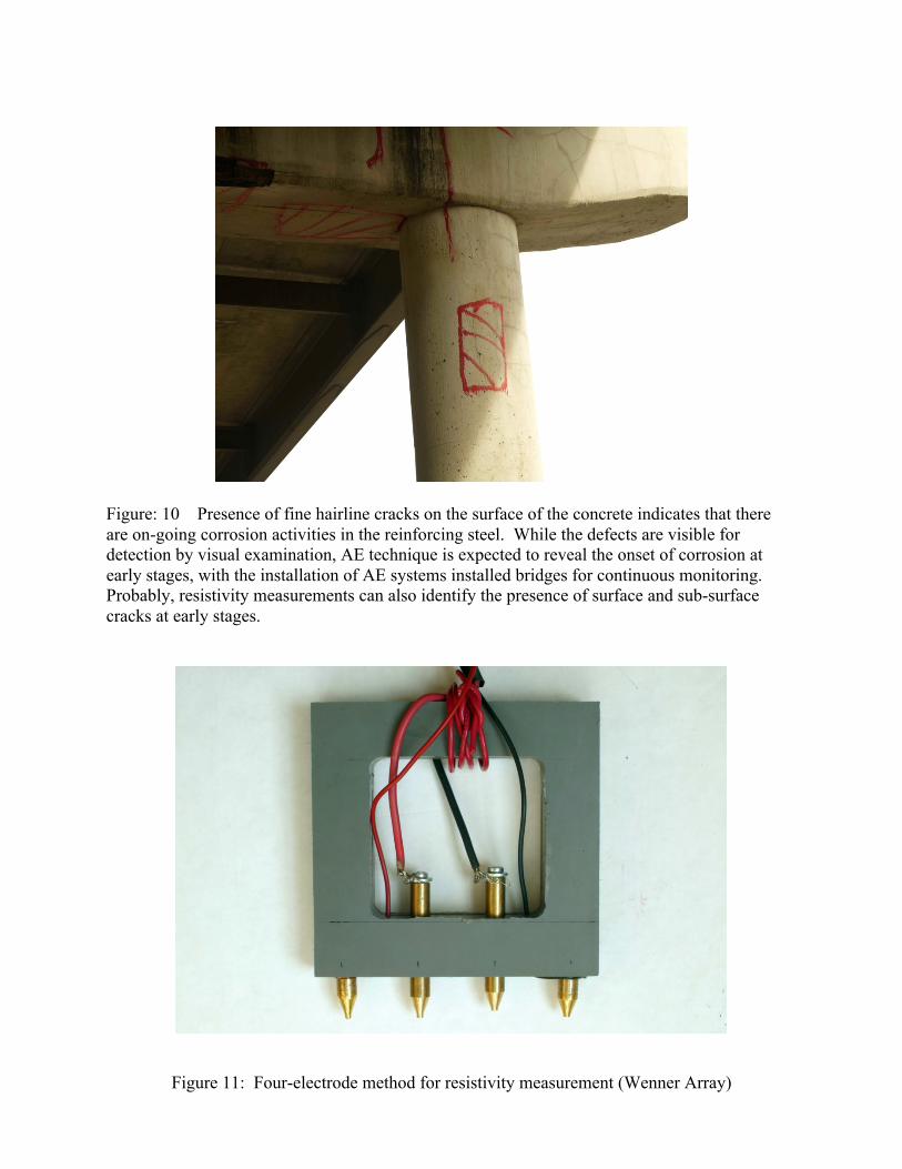
Figure: 10 Presence of fine hairline cracks on the surface of the concrete indicates that there are on-going corrosion activities in the reinforcing steel. While the defects are visible for detection by visual examination, AE technique is expected to reveal the onset of corrosion at early stages, with the installation of AE systems installed bridges for continuous monitoring. Probably, resistivity measurements can also identify the presence of surface and sub-surface cracks at early stages.
Figure 11: Four-electrode method for resistivity measurement (Wenner Array)

18
Summary It is well known that the AE technology is useful in detecting corrosion activities in structures. In storage tanks the AE technology is commonly implemented for the evaluation of corrosion activities. In implementing AE technology in bridges there are concerns. There are several disturbing ambient and unwanted signals that will interfere with the useful signals. Better methods of identifying the signals that arise due to corrosion are to be constantly evolved. Careful judgment has to be applied in selecting the sensor spots and positioning the sensors in concrete structures. Concrete poses additional problems compared to steel structures, in that, the concrete structures attenuate the signals greatly, which demand that more number of sensors need to be used. Commercially manufactured AE systems provide several useful parameters for analyses of data. It is up to the end users to identify the most relevant parameter for interpretation of the nature of event that generated acoustic emission. In current research efforts it was identified that the two parameters namely the Rise time/amplitude (RA) and the Power spectral data are useful in bringing out corrosion signals among other signals.
Permanent installation of AE systems in corrosion prone areas will pre-warn the occurrence of corrosion damages at early stages so as to carry out timely implementation of remedial efforts. Periodical measurement of resistivity on concrete structures will help in identifying the presence of fine surface and sub-surface cracks in concrete and the infusion of corrosive media in concrete. Resistivity measurement alone cannot provide the status of integrity of concrete structures, but it will complement the test results from AE monitoring in assessing the status. Thus the vulnerability to corrosion can be identified using the two NDT techniques. When necessary appropriate surface coating or localized repair work can be carried out on the concrete surface, in timely manner to reduce corrosion attack.