Embed Size (px)
Citation preview

� � ����
�
���������������� ���������
����������
�
�������� ���������������
��� �����������������������������
�
�
�
� �
������
������������������������������
����������������������
�������������������
�����������
�
�
������������� �����������
� ���������
� !����� ���
� �� �����������
�

DT024 YEAR 4 GROUP ASSIGNMENT TUNING OF A VIBRATION ABSORBER FOR A SDOF SYSTEM
�
� � ��
�
�
Table of Contents
Section Page
1 Introduction……………………………………………………………….. 2
2 Damping in Structures………………………………............................ 3
3 Background Theory……………………………………………………… 11
4 Theoretical Modelling using MatLab® Software………………………. 15
5 Experimental Verification of Theory…………………………………… 22
6 Conclusions………………………………………………………………. 28
7 References and Bibliography…………………………………………... 29
�����
�
�

DT024 YEAR 4 GROUP ASSIGNMENT TUNING OF A VIBRATION ABSORBER FOR A SDOF SYSTEM
�
� � ��
Introduction
With the first invention of suspension systems on horse-drawn carriages in the 19th century in the form of leaf springs, greater comfort was available to the passengers and greater control to the driver. Damping of the springs was virtually non-existent, except for frictional energy losses between the leafs of the springs. Common building design also suffers from the same unawareness. Many buildings have been designed and built with no supplementary damping systems included, and therefore have only their own frictional damping properties due to their construction to dissipate vibrational energy that may result from wind, impact or earthquake forces. Not long into the last century, automobile designers recognized the need to damp out the movements of car suspension systems to improve comfort and handling, leading to the invention of shock absorbing struts, or shock absorbers. Their invention has led to the development of all manner of damping and vibration absorbing systems for use in design of machinery, furniture and structures.
Structural engineering has learned from the automobile industry. It is now apparent that the performance of structures is also highly sensitive to damping, therefore it can no longer be left to chance that a structure is adequately stiff and strong enough to resist movement and vibrations.
Many tall and overhanging structures are susceptible to vibrations. Mostly these are structures with low natural damping in combination with mostly rather low natural frequency. Skyscrapers and long bridges are susceptible to resonance created by high winds and seismic activity. In order to mitigate the resonance effect, it is important to build large dampers into their design to interrupt the resonant waves. If these devices are not in place, buildings and bridges can be shaken to the ground, as is witnessed anytime an earthquake happens.

DT024 YEAR 4 GROUP ASSIGNMENT TUNING OF A VIBRATION ABSORBER FOR A SDOF SYSTEM
�
� � ��
1. Damping in Structures
Dampers are used in machines that we likely use every day, including car suspension systems and clothes washing machines. A damping system in a building is much larger and is also designed to absorb the violent shocks of an earthquake.
Fig 1 – Modes of vibration in structures
The size of the dampers depends on the size of the building. Although the structure will have some natural damping, it is sometimes necessary to add damping systems, called Supplementary Damping Systems (SDS) There are broadly four main types of SDS:
• Passive - This is an uncontrolled damper, which requires no input power to operate. They are simple and generally low in cost but unable to adapt to changing needs.
• Active - Active dampers are force generators that actively push on the structure to counteract a disturbance. They are fully controllable and require a great deal of power.
• Semi-Active - Combines features of passive and active damping. Rather than push on the structure they counteract motion with a controlled resistive force to reduce motion. They are fully controllable yet require little input power. Unlike active devices they do not have the potential to go out of control and destabilize the structure.
• Impact - Granular materials are used to improve the damping of vibrating structures.

DT024 YEAR 4 GROUP ASSIGNMENT TUNING OF A VIBRATION ABSORBER FOR A SDOF SYSTEM
�
� � ��
These can be categorized into one of two forms:
1. Distributed Damping Systems
Many small dampers distributed along a structure. Typical in suspension bridges. Distributed Damping Systems need to be located in areas of greatest relative movement between structural elements, where these locations depend highly upon the structural system. These types of systems typically take the following forms:
o Viscoelastic materials to dissipate energy that is placed within multiple structural connections.
o Cross-bracing that incorporates fluid or viscoelastic elements to dissipate energy in multiple frame locations.
o Outrigger, column, or shear-wall systems that incorporate hydraulic or viscoelastic
elements to dissipate energy.
2. Mass Damping Systems
The most effective location for a Mass Damping System (TSD, TLCD, TMD, or AMD) is close to the area of peak amplitude of vibration, which is typically near the top of the building or at the outermost point of an overhanging structure. Some types of Mass Damping Systems include:
o Tuned Sloshing Damper (TSD) - A specifically shaped tank of water incorporating engineered baffles to dissipate energy can be effective in two lateral axes simultaneously. Water can also be used for other purposes in the building.
o Tuned Liquid Column Damper (TLCD) - A U-shaped tank of water incorporating
adjustable gates for dissipating energy is effective in one axis only. Water can be used for other purposes in the building.
o Simple Pendulum Tuned Mass Damper (TMD) - A mass, typically steel or concrete, suspended on cables, tuned to be effective in two axes simultaneously, incorporates hydraulic cylinders to dissipate energy.
o Coupled Pendulum Tuned Mass Damper (TMD)—Two masses—typically steel or concrete—suspended on a combination of cables and struts to minimize vertical height requirements, is tuned to be effective in two axes simultaneously, and incorporates hydraulic cylinders to dissipate energy.
o Active Mass Damper (AMD)—This is a special case of a Mass Damping System that reacts to the building motion in real time. It is mechanically similar in general layout to the

DT024 YEAR 4 GROUP ASSIGNMENT TUNING OF A VIBRATION ABSORBER FOR A SDOF SYSTEM
�
� � ��
TMDs described above, but with the distinction of having a drive mechanism instead of energy dissipaters. Computer control based on building motion sensor input and power are required.
Base Isolation (Distributed:Passive)
Base isolation, which consists of isolating the structure from its foundations, is a very common form of passive control. Bearing pads are placed between structure and foundations, resulting in enhancing the energy absorption capacity of the structure, as well as giving it extra flexibility in order to lengthen its natural period of vibration. The result is an isolation effect, thereby reducing floor acceleration. Types of bearing pads include lead rubber bearings, high damping rubber bearings, elastomeric bearings, viscoelastic bearings and sliding friction bearings. These methods have found great merit is designing for seizmic activity, with examples in China, the United States, Japan and New Zealand all performing satisfactorily, and reducing ground forces being transferred into the structure by as much as two thirds in some cases.
Fig 2 – A structure with base isolation

DT024 YEAR 4 GROUP ASSIGNMENT TUNING OF A VIBRATION ABSORBER FOR A SDOF SYSTEM
�
� � ��
Fig. 3 - Elastomeric Bearing
MR Fluid Dampers (Distributed:Semi-Active)
Magnetorheological fluid (MR) dampers are semi-active devices that change their damping level by varying the amount of current supplied to an internal electromagnet that controls the flow of MR fluid. Inside the MR fluid damper, an electromagnetic coil is wrapped around three sections of the piston. Approximately 5 liters of MR fluid is used to fill the damper's main chamber. During an earthquake, sensors attached to the building will signal the computer to supply the dampers with an electrical charge. This electrical charge then magnetizes the coil, turning the MR fluid from a liquid to a near-solid.
Fig. 4 – An MR fluid damper
Now, the electromagnet will likely pulse as the vibrations ripple through the building. This vibration will cause the MR fluid to change from liquid to solid thousands of times per second, and may cause the temperature of the fluid to rise. A thermal expansion accumulator is fixed to the top of the damper housing to allow for the expansion of the fluid as it heats up. This accumulator prevents a dangerous rise in pressure as the fluid expands.

DT024 YEAR 4 GROUP ASSIGNMENT TUNING OF A VIBRATION ABSORBER FOR A SDOF SYSTEM
�
� � ��
Fig. 5 - A building with MR fluid dampers to protect against earthquakes
Depending on the size of the building, there could be an array of possibly hundreds of dampers. Each damper would sit on the floor and be attached to the chevron braces that are welded into a steel cross beam. As the building begins to shake, the dampers would move back and forth to compensate for the vibration of the shock. When it's magnetized, the MR fluid increases the amount of force that the dampers can exert.
Tuned Mass Dampers (Mass:Passive)
A tuned mass damper (TMD), also known as an active mass damper (AMD) or harmonic absorber, is a device mounted in structures (also used in power transmission towers and cars) to prevent discomfort, damage, or outright structural failure caused by vibration. The force of wind against tall buildings can cause the top of skyscrapers to move more than a metre. This motion can be in the form of swaying or twisting, and can cause the upper floors of such buildings to move. Certain angles of wind and aerodynamic properties of a building can accentuate the movement and cause motion sickness in people.
Tuned mass dampers stabilize against violent motion caused by harmonic vibration. A tuned damper balances the vibration of a system with comparatively lightweight components so that the worst-case vibrations are less intense. Typically, the dampers are huge concrete blocks or steel bodies mounted in skyscrapers or other structures, and moved in opposition to the resonance frequency oscillations of the structure by means of springs, fluid or pendulums. Unwanted vibration may be caused by environmental forces acting on a structure, such as wind or earthquake, or by a seemingly innocuous vibration source causing resonance that may be destructive, unpleasant or simply inconvenient.
The seismic waves caused by an earthquake will make buildings sway and oscillate in various ways depending on the frequency and direction of ground motion, and the height and construction of the building. Seismic activity can cause excessive oscillations of the building which may lead to structural failure. To enhance the building's seismic performance, a proper building design is performed engaging various seismic vibration control technologies.
Fig. 6 - A schematic of a simple spring–mass–damper system used to demonstrate the tuned mass damper system.
A TMD is connected to the structure (bridge, chimney, etc.) at the location where a significant or the biggest vibration is occurring. The device consists of a moving mass, springs and a damping element. The TMD should be placed at the location of the greatest vibration, as then the efficiency is granted to be highest possible with lowest effort. For instance in case the main system with certain

DT024 YEAR 4 GROUP ASSIGNMENT TUNING OF A VIBRATION ABSORBER FOR A SDOF SYSTEM
�
� � �
characteristics (mass = m1, stiffness = k1, natural damping = d1) will vibrate under certain circumstances, a TMD with certain characteristics (mass = m2, stiffness = k2, natural damping = d2) will be firmly set onto this main system. Between main system and the TMD mass a spring element and a damping element is arranged to adapt the TMD in a way, that it is mitigating and partially accommodating the vibrations of the main system.
Main system:
m1= kinetic equivalent mass of structure [kg]
k1 = stiffness coefficient [N/m]
d1 = damping coefficient [N/m/s=Ns/m]
y1 = y1 (t) displacement of m1[m]
F = F(t) = external influence force acting onto m1
TMD:
m2 = moving/swinging mass of TMD [kg]
k2 = stiffness coefficient [N/m]
d2 = damping coefficient [N/m/s=Ns/m]
y2 = y2 (t) displacement of m2 [m]
The absolute displacement y2 of the TMD mass is of less practical
interest compared to the relative displacement of m2 to m1:
z2 = y2 – y1

DT024 YEAR 4 GROUP ASSIGNMENT TUNING OF A VIBRATION ABSORBER FOR A SDOF SYSTEM
�
� � �
Fig. 7 – Responses of a system with and without tuned mass damping
The main system will react with a harmonic vibration – after a short transient phase - if an external harmonic force F = F (t) = F · sin�t is acting and the main system is vibrating stationary with the natural frequency �. In case the main system is not fitted with a TMD, it is reacting with severe vibrations if the exiting frequency of the external force is correlating with the structural natural frequency, which is called resonance. The coupling of a TMD to a main system with mass m2, while considering certain rules for the optimal TMD dimensioning – spring stiffness (k2) and damping (d2) – results in much less reactions of the main system. The mitigation of the vibration of the main system results from counteracting displacements of the damper mass (m2), the frequency adaptation of the springs and the simultaneous damping supplied by the special damping element.
Vibration Absorbers (Mass:Passive)
As stated earlier, lightly damped inertial appendages, known as vibration absorbers, are effective vibration absorption devices. They are mainly used to cancel the structural vibration caused by a single frequency disturbance. To study the vibration cancelation effect of this type of passive vibration absorption device, we attach a vibration absorber to a Single Degree of Freedom, or SDOF (spring-mass-dashpot) system resembling a flexible structure subject to the disturbance force F. Combination of the structure and the vibration absorber results in a 2 Degree of Freedom (2DOF) system shown in Figure 5. Note that similar to a TMD, a vibration absorber adds an additional degree of freedom to the structure it is appended to. The equation of motion of the system is shown in Fig. 6.
�
Fig. 8 – A simple vibration absorber model
�
�Equation 1��
�

DT024 YEAR 4 GROUP ASSIGNMENT TUNING OF A VIBRATION ABSORBER FOR A SDOF SYSTEM
�
� � � �
In the absence of damping element in the appendage of Figure 6, i.e., c2=0, three of the entries of the damping matrix of Equation 1 become zeros resulting in a pair of imaginary zeros in the transfer function mapping the disturbance force F to the structural displacement x1. The location of this zero is on the imaginary axis of the s plane at (k2/m2)
0.5 which is the natural frequency of the appendage. When k2 and m2 are selected (appendage is tuned) to match this natural frequency to the disturbance frequency, the structural vibration will be attenuated at that frequency. This is the inner-working of a vibration absorber which is in fact a TMD with negligible damping. Vibration absorbers are used primarily for alleviating the forced vibration response of (not adding damping to) the structure.

DT024 YEAR 4 GROUP ASSIGNMENT TUNING OF A VIBRATION ABSORBER FOR A SDOF SYSTEM
�
� � ���
2. Background Theory
Basic Single Degree of Freedom (SDOF) System Theory
To best understand the theory of tuned mass damping, the basic theory of single degree of freedom systems must be addressed first. A single degree of freedom system is basically a system which only moves along one axis. This is easily modelled using a mass hanging from a spring. When the mass is set in motion vertically by raising it and then dropping it, or stretching it down and releasing it only oscillates up and down.
Fig. 9 SDOF system
Equations of Motion:
As can be seen from the sketch above the forces on the system can be resolved in direction to produce the equation of motion for a single degree of freedom system.
Fapplied = Fstiffness + Fdamping + Finertia
Fapplied = The force applied to the mass = F(t)
Fstiffness= The force imparted by the stiffness of the spring on the system = k
Fdamping= The damping force which is directly proportional to velocity = c
Finertia = The inertial force which is directly proportional to acceleration = m
The force equation can now be manipulated as follows
F(t)= k + c + m

DT024 YEAR 4 GROUP ASSIGNMENT TUNING OF A VIBRATION ABSORBER FOR A SDOF SYSTEM
�
� � ���
Where k is the stiffness of the spring, c is a constant proportional to damping and m is the mass at the end of the spring. The term u denotes the displacement and the dots denote the derivatives of displacement i.e. velocity and acceleration.
For the purpose of our experiment we analyzed an undamped free vibrating system. The motion equations were altered to show that because there was no damping and no applied force the motion equation was,
k + m
Tuned Mass Damper Theory
In essence a tuned mass damper is a vibration absorber. When excessive vibration occurs in a system the displacements (amplitude) can become large and have a violent effect on the system. The absorber properties such as its mass and natural frequency are altered to reduce the amplitude of the primary system. The effect of a simple vibration absorber can be seen in this problem from beards
Sample Problem
A machine tool of mass 3000kg has a large resonance vibration in the vertical direction at 120Hz. To control this resonance an undamped vibration absorber of 600kg is fitted, tuned to 120Hz. Find the frequency range in which the amplitude of the machine is with the absorber fitted than without.
If (u) with absorber = (u) without absorber
Multiplying out and putting
Where circular frequency and natural frequency
Therefore
This simple problem shows that vibrations in a system can be reduced by adding a mass with a tuned frequency.
Employed Theory
For this assignment the system we analyzed was an undamped free vibration system. The system was set in motion by raising the mass above its equilibrium position. The final system is composed of a primary system which is the large mass( M1) and spring with stiffness (K1). The secondary system which is the tuned mass has a mass of (M2) and a spring of stiffness (M2).
DT024 YEAR 4 GROUP ASSIGNMENT TUNING OF A VIBRATION ABSORBER FOR A SDOF SYSTEM
�
� � ���
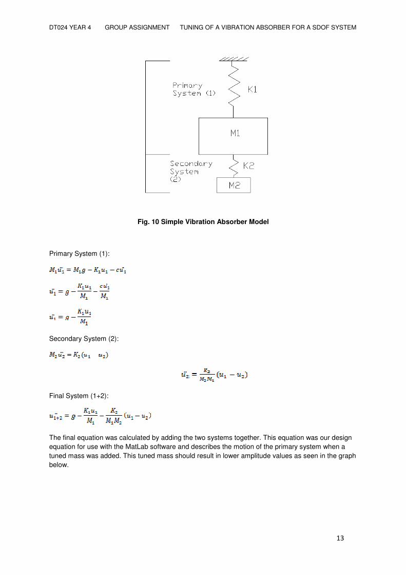
Fig. 10 Simple Vibration Absorber Model
Primary System (1):
Secondary System (2):
Final System (1+2):
The final equation was calculated by adding the two systems together. This equation was our design equation for use with the MatLab software and describes the motion of the primary system when a tuned mass was added. This tuned mass should result in lower amplitude values as seen in the graph below.

DT024 YEAR 4 GROUP ASSIGNMENT TUNING OF A VIBRATION ABSORBER FOR A SDOF SYSTEM
�
� � ���
Fig. 11 Tuned Mass Vibration Absorber Graph

DT024 YEAR 4 GROUP ASSIGNMENT TUNING OF A VIBRATION ABSORBER FOR A SDOF SYSTEM
�
� � ���
3. Theoretical Modelling using MatLab® Software
�
The objective of the report is to investigate the behaviour of a first order system to a varying amount of vibration absorption using a vibration absorber. This system is only used when a particularly large resonance exists, as added dampers only reduce vibration of the structure as opposed to eliminated. A vibration absorber is simply spring body system that is added to the system; that ‘parameters of the absorber are chosen so that the amplitude of the vibration of the structure is greatly reduced, or even eliminated, at a frequency’ which is usually chosen to be close to the original large resonance. (Ref 1)
The author will analyse the displacement of the primary system as time progresses, i.e. 5 second period. Then author will add the vibration absorber to the primary system and analyse the new displacements of the primary structure as time progresses. After this is done the author will change the value of the secondary mass, m, to show how tuning it affects the displacements over time.
Damping outside of the vibration absorber will be neglected for simplicity of comparison between systems.
The system was tuned using the K1/M1=K2/M2 to get the correctly tuned mass.
The issue of tuning the mass to a specific frequency now arises.
�
�
Fig. 12 Simple Vibration Absorber Model
This system model will be now modelled on MatLab®, (the second row of notation will be used in MatLab®)
M = m1 = mass of primary system
K = k1= stiffness of primary spring (N/m)
k= k2 = stiffness of vibration absorber spring (N/m)
m = m1 = tuned mass of primary system
X =y1 = deflection of primary system

DT024 YEAR 4 GROUP ASSIGNMENT TUNING OF A VIBRATION ABSORBER FOR A SDOF SYSTEM
�
� � ���
x= y2 = deflection of secondary system
Using the ‘receptance’ technique, which makes for more convenient analysis, we split the system into sub-systems A and B as shown in the Fig. 11 (rotated 90o anticlockwise for space)
Fig. 13 Sub-systems A and B
Firstly the author will analyse the primary system;
Primary System
Fig. 14 Primary System
MatLab® notation;
The equation of motion (assuming y is positive and neglecting damping) is: My’’ = mg – ky
Rearranging the equation we get: y’’ = g – k1/m1*y
The author will use p instead of y for the displacement of primary system.
These equations can be written as first order differential equations by making the following substitution: p1 = y and p2 = y’
Using this we can now create a simple program that will allow us to calculate the displacement and velocity of the spring with time using MatLab®. The program is as follows:
function dpdt = mck32(t,p) m1=10; k=300; dpdt= [p(2);9.81 -(k/mass)*p(1)]; �

DT024 YEAR 4 GROUP ASSIGNMENT TUNING OF A VIBRATION ABSORBER FOR A SDOF SYSTEM
�
� � ���
We will now define this as a m-file, i.e. an equation which can be referenced in MatLab®.
We save this as an m-file in MatLab® called ‘mck32’, i.e. the author’s 32nd attempt. We now go to matlab and call this program in the function ODE45. This function will perform the actual calculation using the variable of time (t) and primary displacement (p). This function is executed using the code below:
[t,p] = ode45(@mck32, [0 5], [0 0])
When this is entered MatLab® runs the calculation within the program. It calculates the displacement and velocity of the mass with time. We plot this to show the result:
Fig. 15 Time History Graph
With velocity in green and displacement in blue
This graph gives the free undamped vibration of the primary system;
Let values of the results function dp/dt = a global function so it can accessed by the next ode45 equation, this is to form a loop.
Secondary system addition
In this step we add the vibration absorber to the primary system.

DT024 YEAR 4 GROUP ASSIGNMENT TUNING OF A VIBRATION ABSORBER FOR A SDOF SYSTEM
�
� � ��
Fig. 16 Primary and Secondary Systems
This gives the formulae:
P1 = displacement of primary system
P1-Yb = displacement of secondary system
For the vibration absorber alone,
Y’’ = k2/M2(p1-y)
Adding this to the equation of the primary system gives;
y’’ = g – k1/m1*P1 – k2/M1(P1-yb/M2)
this in MatLab® code gives;
function dydt = mck33(t,y) globalp; m1=10; k1=300; m2=2.5; k2=75; dydt= [y(2);9.81 - (k1/m1)*y(1)-(k2/m2*m1)*y(1)+(k2/m2*m1)*p(2)];
By adding the
function dydt = mck33(t,y) globalp; m1=10; k1=300; m2=2.5; k2=75; dydt= [y(2);9.81 - (k1/m1)*y(1)-(k2/m2*m1)*y(1)+(k2/m2*m1)*p(2)];�

DT024 YEAR 4 GROUP ASSIGNMENT TUNING OF A VIBRATION ABSORBER FOR A SDOF SYSTEM
�
� � ��
Fig. 17 Free tuned mass vibration of the system
This is the free tune mass damped vibration of the ‘complete’ system.
It can be seen from this graph that the amplitude is greatly reduced while the frequency is nearly halved; i.e. there is almost a minimum frequency with the absorber when it would have been a max frequency without.
Plotting the total masses (i.e. m1+m2 in primary system) with just the primary spring will give a graph like this; as expected the amplitude is far higher, due to the lack of spring between the masses, than simply the original mass.
Fig. 18 Plot of masses with primary spring alone

DT024 YEAR 4 GROUP ASSIGNMENT TUNING OF A VIBRATION ABSORBER FOR A SDOF SYSTEM
�
� � � �
Finally we wish to see how the above plotted values will vary with changing damping values.
This is done by altering the value of the damping in the original program ‘mck33’ altering the mass m1 in both the positive and negative direction. Each time the calculation is done we save the values of displacement and velocity into a blank matrix, we then use MatLab®‘s own surface plot function to show the result.
Fig. 19 MatLab® surface plot
This is not from MatLab® as when the author tried to perform the surface plot function the computer froze or the MatLab® program closed down. This is however what the plot should look like for displacements. This graph can be used to verify damping. (Ref3)
Fig. 20 End view of the 3D graph (Ref3)
Fig. 21 Effect of absorber damping on system (c=� ‘undampened’ and c=0 ‘vibration absorbed’). Disregard p curve-unrelated.

DT024 YEAR 4 GROUP ASSIGNMENT TUNING OF A VIBRATION ABSORBER FOR A SDOF SYSTEM
�
� � ���
From these graphs we can see that the response of the primary system can be minimised over a wide range of exciting frequencies by choosing the value of m2 carefully. This shows tune mass dampening to be a viable solution were resonance is concerned.
Fig. 22 Microsoft Excel® secondary system m2 mass calculator

DT024 YEAR 4 GROUP ASSIGNMENT TUNING OF A VIBRATION ABSORBER FOR A SDOF SYSTEM
�
� � ���
4. Experimental Verification of Theory
�
Test procedures:
The stiffness of the elastic bands was found by applying loads to the end of the band and recording the displacements produced. The damp out times of the primary and combined primary and secondary systems were recorded for a range of values of applied m2 masses centred on the calculated optimal tuned mass value.
�
1. Stiffnesses
�
���
���������� ��������� ��������������� ��� ������!!�����
� � "���� � �
" �� "���� "�� " ��� ��"�������
" �� "��� "� � " �� � "�����
" � "�� "���� " ��� �"������
"��� �"����� "���� " ��� ��"����
Table 1
�
�
�
Fig. 23
�

DT024 YEAR 4 GROUP ASSIGNMENT TUNING OF A VIBRATION ABSORBER FOR A SDOF SYSTEM
�
� � ���
�
�
�
� � ��� � �
�����
����� ��������� ��������������� ��� ������!!�����
� � "� �� � �
" �� "���� "���� " �� �"���
" �� "��� "���� " ��� ��" ������
" � "�� "���� " �� �" ��
"��� �"����� "���� " ��� ��"� �
Table 2
�
�
�
Fig. 24
�
Fig. 20 SDOF system
�
�
�
�
DT024 YEAR 4 GROUP ASSIGNMENT TUNING OF A VIBRATION ABSORBER FOR A SDOF SYSTEM
�
� � ���
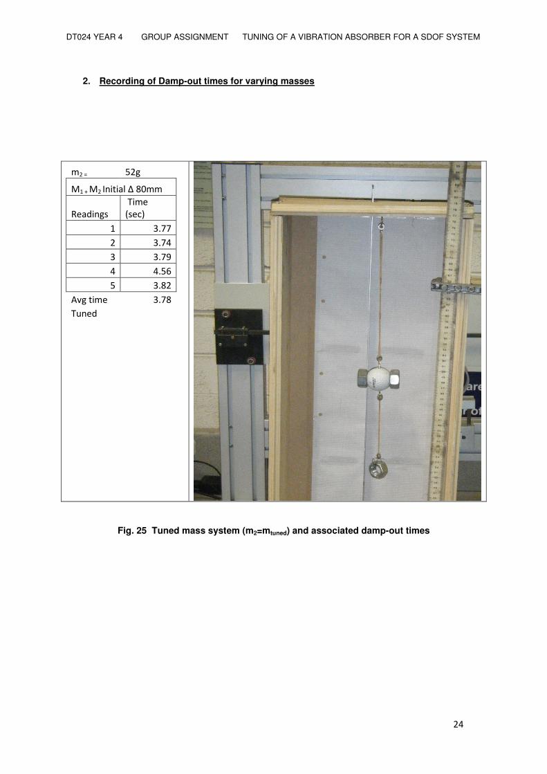
2. Recording of Damp-out times for varying masses
#��$� ����
���%����&��������� ##�
'������!�
�(�#���
�!����
�� �"���
�� �"���
�� �"��
�� �"���
�� �"��
)*����#�� �"��
(+���� ��
��
Fig. 25 Tuned mass system (m2=mtuned) and associated damp-out times

DT024 YEAR 4 GROUP ASSIGNMENT TUNING OF A VIBRATION ABSORBER FOR A SDOF SYSTEM
�
� � ���
#��$� ����
���%����&���������
##�
'������!�
�(�#���
�!����
�� �" ��
�� �"��
�� �"���
�� �"���
�� �"��
)*����#�� �"���
� ��
��
Fig. 26 m2>mtuned and associated damp-out times
�
�
�
�
�

DT024 YEAR 4 GROUP ASSIGNMENT TUNING OF A VIBRATION ABSORBER FOR A SDOF SYSTEM
�
� � ���
�
#��$� ����
���%����&���������
##�
'������!�
�(�#���
�!����
�� �"���
�� �"���
�� �"���
�� �"���
�� �"��
)*����#�� �"� ���
,-����.�/-��#�������+�����/��.�0+����1�
Fig. 27 m2<mtuned and associated damp-out times
�
Fig. 28 Plot of differing m2 values versus damp-out time. The calculated optimum tuned mass m2 value (52g) clearly reduces vibrations most.
(-�!��.�/-�!-�2 !��-����-��*�3.������.�!/��!��2 ��-��-���+����#�!!�-�!��-���.����!��*�3.������
!+//.�!!���4��!��5/�����"�6 -����-��#����#�!!�2 �!����.��!�����������-��!������.1�!1!��#���+!�����
�.����.�*�3.��������5������/.�#�.1�!1!��#�������!���.�!+����-����#����.��-��!1!��#������#�����.�!��
2 �!����.��!��"�6 -����-��#�����#�!!�2 �!����.��!�����������-�.��2 �!����������.����.�*�3.������
.�!/��!���.�#��-��/.�#�.1�!1!��#������-�.���.���-����#����.��-��!1!��#������#�����.�!��2 �!�
�.����.��-����-���+����#�!!�!1!��#"��(-���+����#�!!��-�.���.����+!�!��-�����!��.�!/��!���.�#��-��
!1!��#4������3!�.3!��-��#�!���#�+���������.�1��.�#��-��/.�#�.1�!1!��#"�

DT024 YEAR 4 GROUP ASSIGNMENT TUNING OF A VIBRATION ABSORBER FOR A SDOF SYSTEM
�
� � ���
5. Conclusions
It is clear that the vibrational response of a system can be altered by appending one or more secondary vibrating systems to it. In this case, we attached a small vibrating mass secondary system to a primary single degree of freedom system. Maximum primary system response is achieved by matching the frequency of the secondary system with the natural frequency of the first. This excites the primary system response, and is said to be in a state of resonance. Experimental results found that a secondary system mass value of about 72g will cause this to occur. In real structures this may give rise to dangerous conditions.
Conversely, minimum primary system response is achieved by a secondary system mass value of approximately 52g being attached to the primary system. The amplitudes of the two systems oppose each other resulting in a net amplitude much less than the primary system natural amplitude. The effect of ‘tuning’ the secondary system mass value in this way is such that the vibrational response of the primary system is minimised. Simulation of these effects is a relatively straightforward affair with software like mathcad, and shows that theory can quite accurately predict the necessary tuned parameters.
In real structures with long overhangs or very tall buildings, the introduction of damping systems to counteract wind, impact and earthquake effects, assures the safety and comfort of the occupants as well as the stability and strength of the structure. This is especially crucial in more recent times when designs of slender lightweight structures are more popular than ever.

DT024 YEAR 4 GROUP ASSIGNMENT TUNING OF A VIBRATION ABSORBER FOR A SDOF SYSTEM
�
� � ��
6. References
1. Beards, C.F., (1983) Structural Vibration Analysis. Ellis Horwood, Chichester.
2. Biran, A.; Breiner, M., (2002) MatLab For Engineers 6, Pearson, London.
3. Stroscher. PowerPoint presentation. Online. www14.informatik.tu muenchen.de/konferenzen/ Jass06/courses/4/Stroscher/Stroscher.ppt
Bibliography
Beards, C.F., (1996) Structural Vibration – Analysis and Damping. Arnold, London.
Clough, R. W.; Penzien, J., (1975) Dynamics of Structures. McGraw-Hill, New York.
‘How Smart Structures Will Work’. How Stuff Works. Online. http://science.howstuff works.com/smart-structure2.htm
‘Tuned Mass Dampers’, pdf. Maurer Publications. Online.http://www.maurer.co.uk/ noise_reduction.cfm
‘Tuned Mass Damper’, en.wikipedia.org.Online.http://en.wikipedia.org /wiki/Tuned_mass_damper