Embed Size (px)
Citation preview

24 www.paintsquare.comJ P C L A p r i l 2 0 0 9
his article is the second part of a report on a nationallyfunded project on the performance testing of different
corrosion protection methods for offshore wind towers undersite and laboratory conditions. Part 1, published in the April 2008
JPCL, reported on the rationale behind, and setting up of, the testprogram. The present article discusses the test results.
BackgroundTesting was conducted for performance of coatings in the underwater,intermediate, and splash zones. Six coating systems were tested,although not all systems were tested in all three zones. The coatings wereapplied over steel blast cleaned with steel grit and in accordance with ISO8504-2. Uncoated steel with cathodic protection was also tested. Thesystems tested are shown in the box on the opposite page.
Editor’s Note: This article is the secondpart of the authors’ report on testingcoating performance on offshore wind towers. The first part,“Investigating Corrosion Protection of Offshore Wind Towers,” waspublished in the April 2008 JPCL (pp. 30–43) and won SSPC’shighest editorial honor, the Outstanding Paper Award, which wasannounced at PACE 2009, held February 15-18, 2009, in NewOrleans. (See also “Awards” story, pp. 57–59, of this issue.)Part 1 described the rationale behind the authors’ testprogram as well as its setup. In addition toappearing in the print edition of the April2008 JPCL, Part 1 can also be accessed inthe online edition of the April 2008 JPCL, found in the “Publications”section of JPCL’s electronic home, www.paintsquare.com. Part 3of the report will be published in an upcoming issue of JPCL.
TInvestigating Corrosion Protection of Offshore Wind Towers
Part 2: Results of the Site TestsInvestigating Corrosion Protection of Offshore Wind Towers
Part 2: Results of the Site Tests
Therefore, results of fouling assessmentmay to some extent depend on the sea-son.The samples in this study were
Fouling and Biological GrowthFouling on offshore structures is a well-known phenomenon. In the sector of off-shore gas and oil extraction, variousstudies have been performed.1,2,3 Somestudies on the fouling on offshore windenergy towers have also beenreported.4,5,6
The type and quantity of foulingspecies will depend on certain environ-mental conditions, namely, temperature,water composition, and the kinematics ofthe water. Nutrient concentration, in par-ticular, is affected by the season.3
25
By Andreas W. Momber, Ph.D.,
Muehlhan AG, Hamburg, Germany;
Peter Plagemann, Ph.D.,
Volkmar Stenzel, Ph.D.,
Fraunhofer Institute for
Manufacturing and Applied Materials
Research, Bremen, Germany; and
Michael Schneider, Ph.D.,
Fraunhofer Institute for Ceramic
Technologies and Systems,
Dresden, Germany
released in the summer season (July).Some environmental conditions applyingto the test site are listed in Table 1.Fouling can affect the corrosion of
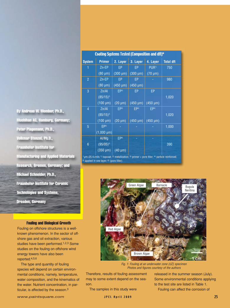
Coating Systems Tested (Composition and dft)*
System
1
2
3
4
5
6
Primer
Zn-EP
(80 µm)
Zn-EP
(80 µm)
Zn/Al
(85/15)2)
(100 µm)
Zn/Al
(85/15)2)
(100 µm)
EP5)
(1,000 µm)
Al/Mg
(95/05)2)
(350 µm)
2. Layer
EP
(300 µm)
EP
(450 µm)
EP3)
(20 µm)
EP3)
(20 µm)
-
EP6)
(40 µm)
3. Layer
EP
(300 µm)
EP
(450 µm)
EP
(450 µm)
EP4)
(450 µm)
-
-
4. Layer
PUR1)
(70 µm)
-
EP
(450 µm)
EP4)
(450 µm)
-
-
Total dft
750
980
1,020
1,020
1,000
390
*µm÷25.4=mils 1) topcoat; 2) metallization; 3) primer + pore filler; 4) particle reinforced;5) applied in one layer; 6) (pore filler)
Fig. 1: Fouling at an underwater zone (UZ) specimenPhotos and figures courtesy of the authors
Green Algae Barnacle BugulaNeritina
Red Algae
Brown Algae
J P C L A p r i l 2 0 0 9www.paintsquare.com
steel in several ways: creation of areas oftrapped water; oxygen concentrationcells; sites for aerobic bacteria; removalof metal.7 It is, however, not clear if foul-ing and marine growth can affect the per-formance of protective coatings.
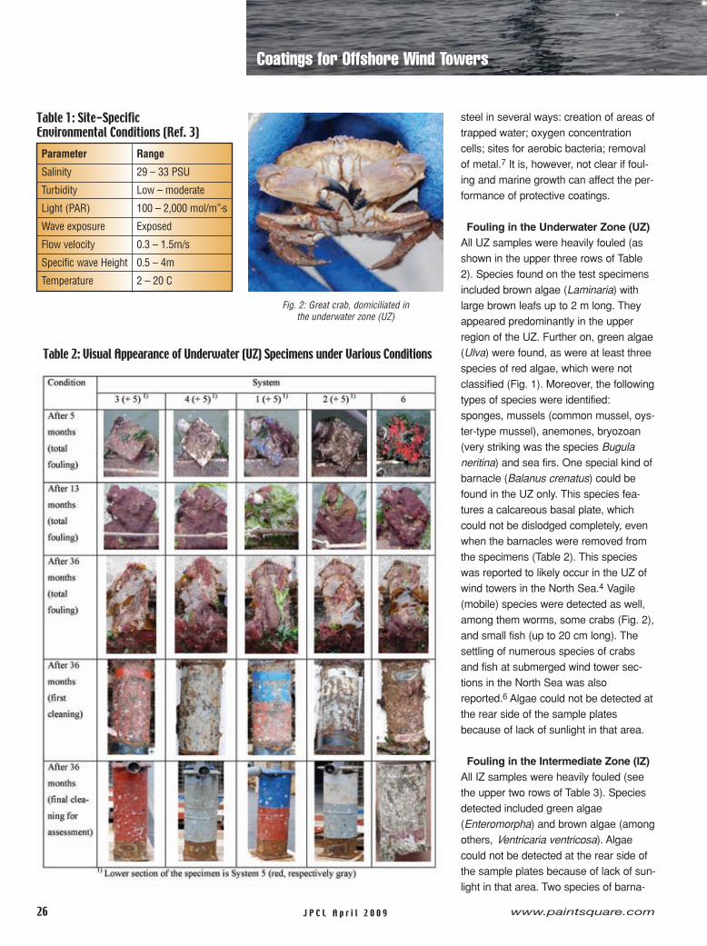
Fouling in the Underwater Zone (UZ)All UZ samples were heavily fouled (asshown in the upper three rows of Table2). Species found on the test specimensincluded brown algae (Laminaria) withlarge brown leafs up to 2 m long. Theyappeared predominantly in the upperregion of the UZ. Further on, green algae(Ulva) were found, as were at least threespecies of red algae, which were notclassified (Fig. 1). Moreover, the followingtypes of species were identified:sponges, mussels (common mussel, oys-ter-type mussel), anemones, bryozoan(very striking was the species Bugulaneritina) and sea firs. One special kind ofbarnacle (Balanus crenatus) could befound in the UZ only. This species fea-tures a calcareous basal plate, whichcould not be dislodged completely, evenwhen the barnacles were removed fromthe specimens (Table 2). This specieswas reported to likely occur in the UZ ofwind towers in the North Sea.4 Vagile(mobile) species were detected as well,among them worms, some crabs (Fig. 2),and small fish (up to 20 cm long). Thesettling of numerous species of crabsand fish at submerged wind tower sec-tions in the North Sea was alsoreported.6 Algae could not be detected atthe rear side of the sample platesbecause of lack of sunlight in that area.
Fouling in the Intermediate Zone (IZ)All IZ samples were heavily fouled (seethe upper two rows of Table 3). Speciesdetected included green algae(Enteromorpha) and brown algae (amongothers, Ventricaria ventricosa). Algaecould not be detected at the rear side ofthe sample plates because of lack of sun-light in that area. Two species of barna-
26 www.paintsquare.comJ P C L A p r i l 2 0 0 9
Coatings for Offshore Wind Towers
Parameter Range
Salinity 29 – 33 PSU
Turbidity Low – moderate
Light (PAR) 100 – 2,000 mol/m”•s
Wave exposure Exposed
Flow velocity 0.3 – 1.5m/s
Specific wave Height 0.5 – 4m
Temperature 2 – 20 C
Table 1: Site-SpecificEnvironmental Conditions (Ref. 3)
Table 2: Visual Appearance of Underwater (UZ) Specimens under Various Conditions
Fig. 2: Great crab, domiciliated inthe underwater zone (UZ)
J P C L A p r i l 2 0 0 9 27www.paintsquare.com
fouling, whereas the sample 1b was asheavily fouled as the systems with anEP-based upper coat. It was noted, how-ever, that the rear areas of the panelswere much less populated compared tothe front. Basically, only barnacles set-tled in the rear areas (row 4, Table 3),most likely because of the lack of UVlight.
Coating Performancein the Underwater Zone
Performance after 5 and 13 MonthsThe samples were assessed after 5months and after 13 months. Results ofthese surveys are reported elsewhere.8,9
The results obtained after 13 months arebriefly recapitulated here. A striking, andrather unexpected, feature was heavyfouling on the underwater samples(upper two rows, Table 2). The foulingconsisted of small barnacles and a darkbiofilm (algae, sponges). The severity ofthe fouling differed notably. The samplewith System 6 showed the most severefouling; it was almost completely cov-ered with barnacles. System 5 exhibitedthe least severe coverage with barnaclesbut was covered extensively withbiofilms. The coating performance couldnot be assessed in detail. At a few smallareas, the fouling was carefullyremoved, and the coatings were visuallyinspected. No signs of deterioration weredetected.
Performance after 36 MonthsThe samples were mechanically cleanedwith a wood scraper and subsequenthigh-pressure water washing to visuallyassess the conditions of the coatings(Table 2).System 3 showed slight delamination
at the front after cleaning, perhaps dueto mechanical damage and subsequentdeterioration. The steel/primer interfaceexhibited initial delamination. System 4did not show any damage to thesurface. Slight initial delamination atthe steel/primer interface was noted.
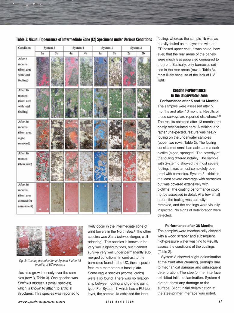
Table 3: Visual Appearance of Intermediate Zone (IZ) Specimens under Various Conditions
Fig. 3: Coating delamination at System 5 after 36months of UZ exposure
cles also grew intensely over the sam-ples (row 3, Table 3). One species wasElminius modestus (small species),which is known to attach to artificialstructures. This species was reported to
likely occur in the intermediate zone ofwind towers in the North Sea.4 The otherspecies was Semi balanus (larger, well-adhering). This species is known to bevery well aligned to tides, but it cannotsurvive very well under permanently sub-merged conditions. In contrast to thebarnacles found in the UZ, these speciesfeature a membranous basal plate.Some vagile species (worms, crabs)were also found. There was no relation-ship between fouling and generic painttype. For System 1, which has a PU toplayer, the sample 1a exhibited the least
Syst
emCo
atin
gge
nera
l(b
liste
rs,d
efec
ts)
Coat
ing
atw
eld
seam
1)
Dela
min
atio
nst
eel/
prim
erDe
lam
inat
ion
prim
er/t
opco
atAd
hesi
on(p
ull-o
ffte
st)2
)
28 www.paintsquare.comJ P C L A p r i l 2 0 0 9
20340 for newly applied coatings forimmersion service.13 On the otherhand, only System 1 showed fracturesin the coating system alone, not in thesteel-primer interface.The internal areas, originally filled
with seawater, were inspected as well.They showed signs of oxidation, but, ingeneral, the corrosion was not severe,and pitting was not detected. Signs ofmore severe oxidation were recognizedalong a stripe that ran exactly alongthe weld seam (see image for System4, Table 4). This feature was interestingbecause the weld seam was attachedonly to the external surface.Metallurgical changes in the steel, orig-inating from the welding process, mighthave caused this phenomenon.The results of the assessment pro-
cedure are listed in Table 5, whichshows that they did not allow for a reli-able ranking of the systems in terms ofcoating performance (except for
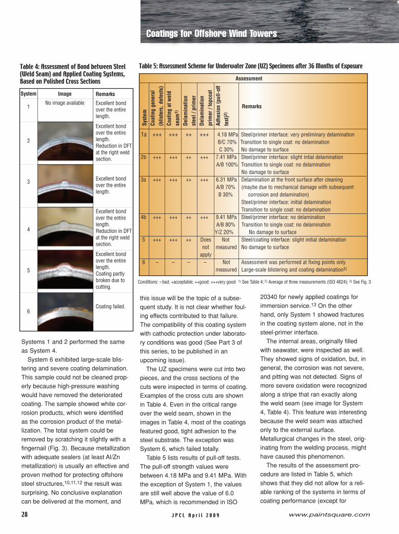
Table 4: Assessment of Bond between Steel(Weld Seam) and Applied Coating Systems,Based on Polished Cross Sections
1a +++ +++ ++ +++ 4.18 MPa Steel/primer interface: very preliminary delaminationB/C 70% Transition to single coat: no delaminationC 30% No damage to surface
2b +++ +++ ++ +++ 7.41 MPa Steel/primer interface: slight intial delaminationA/B 100% Transition to single coat: no delamination
No damage to surface3a +++ +++ ++ +++ 6.31 MPa Delamination at the front surface after cleaning
A/B 70% (maybe due to mechanical damage with subsequentB 30% corrosion and delamination)
Steel/primer interface: initial delaminationTransition to single coat: no delamination
4b +++ +++ ++ +++ 9.41 MPa Steel/primer interface: no delaminationA/B 80% Transition to single coat: no delaminationY/Z 20% No damage to surface
5 +++ +++ ++ Does Not Steel/coating interface: slight initial delaminationnot measured No damage to surfaceapply
6 – – – – Not Assessment was performed at fixing points onlymeasured Large-scale blistering and coating delamination3)
Assessment
Remarks
Table 5: Assessment Scheme for Underwater Zone (UZ) Specimens after 36 Months of Exposure
Systems 1 and 2 performed the sameas System 4.System 6 exhibited large-scale blis-
tering and severe coating delamination.This sample could not be cleaned prop-erly because high-pressure washingwould have removed the deterioratedcoating. The sample showed white cor-rosion products, which were identifiedas the corrosion product of the metal-lization. The total system could beremoved by scratching it slightly with afingernail (Fig. 3). Because metallizationwith adequate sealers (at least Al/Znmetallization) is usually an effective andproven method for protecting offshoresteel structures,10,11,12 the result wassurprising. No conclusive explanationcan be delivered at the moment, and
this issue will be the topic of a subse-quent study. It is not clear whether foul-ing effects contributed to that failure.The compatibility of this coating systemwith cathodic protection under laborato-ry conditions was good (See Part 3 ofthis series, to be published in anupcoming issue).The UZ specimens were cut into two
pieces, and the cross sections of thecuts were inspected in terms of coating.Examples of the cross cuts are shownin Table 4. Even in the critical rangeover the weld seam, shown in theimages in Table 4, most of the coatingsfeatured good, tight adhesion to thesteel substrate. The exception wasSystem 6, which failed totally.Table 5 lists results of pull-off tests.
The pull-off strength values werebetween 4.18 MPa and 9.41 MPa. Withthe exception of System 1, the valuesare still well above the value of 6.0MPa, which is recommended in ISO
Conditions: –bad; +acceptable; ++good; +++very good 1) See Table 4; 2) Average of three measurements (ISO 4624); 3) See Fig. 3
System
1
2
3
4
5
6
Remarks
Excellent bondover the entirelength.
Excellent bondover the entirelength.Reduction in DFTat the right weldsection.
Excellent bondover the entirelength.
Excellent bondover the entirelength.Reduction in DFTat the right weldsection.
Excellent bondover the entirelength.Coating partlybroken due tocutting.
Coating failed.
Image
No image available
Coatings for Offshore Wind Towers
J P C L A p r i l 2 0 0 9 29www.paintsquare.com
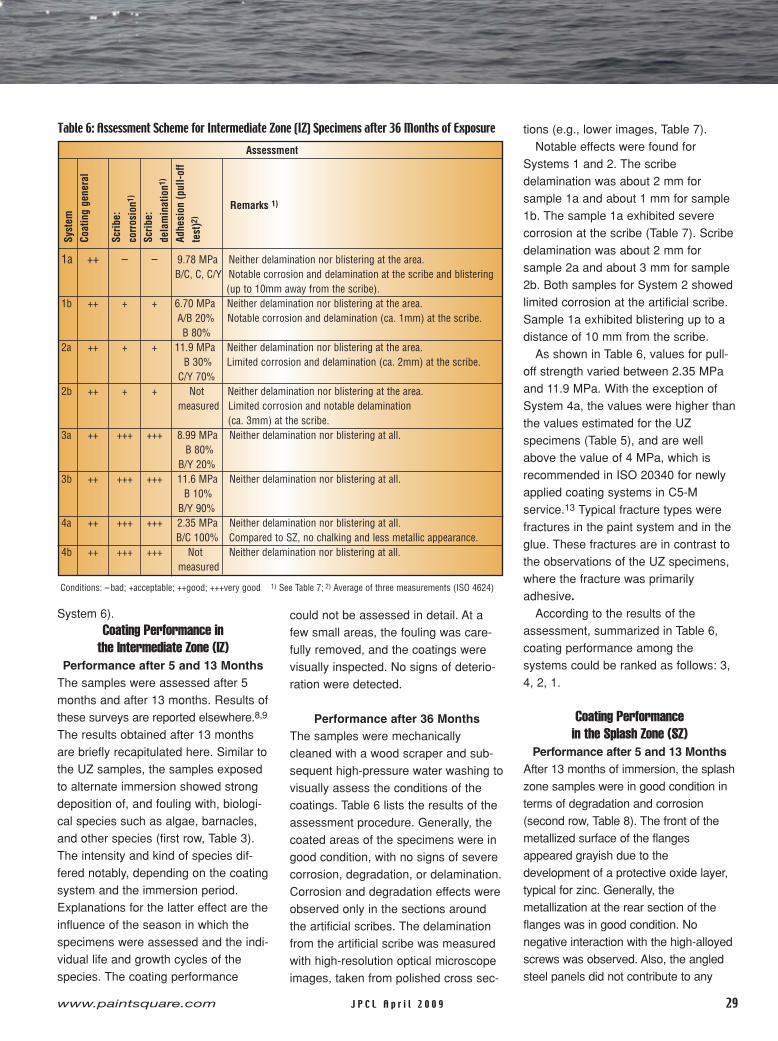
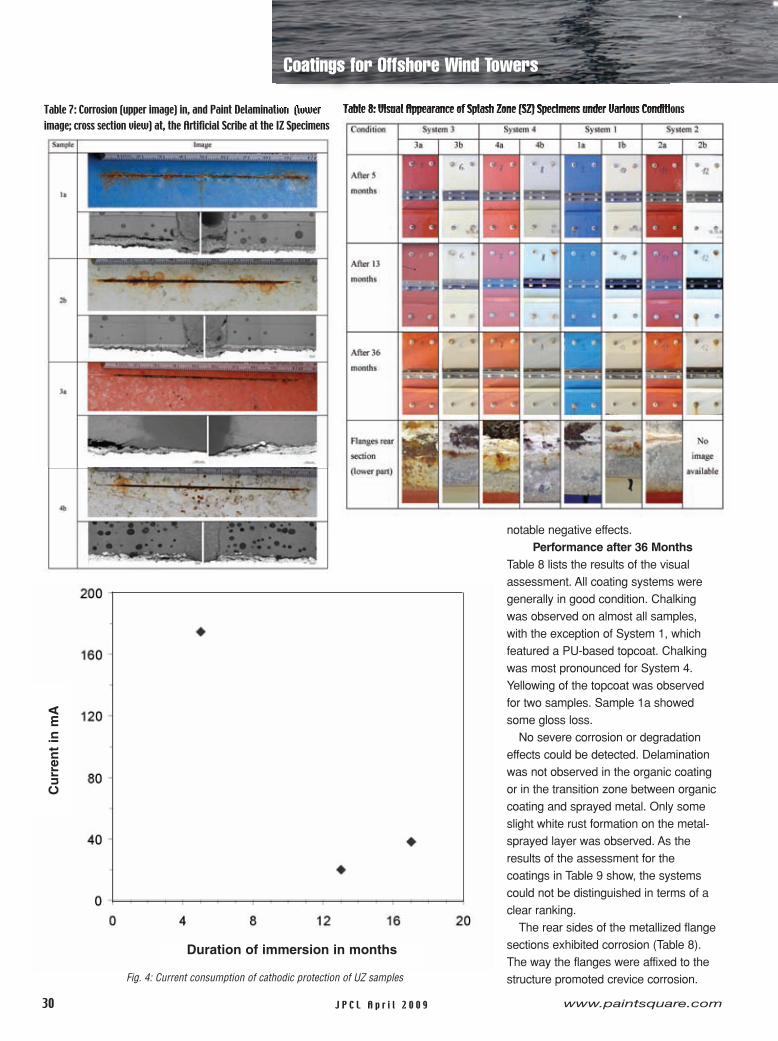
tions (e.g., lower images, Table 7).Notable effects were found for
Systems 1 and 2. The scribedelamination was about 2 mm forsample 1a and about 1 mm for sample1b. The sample 1a exhibited severecorrosion at the scribe (Table 7). Scribedelamination was about 2 mm forsample 2a and about 3 mm for sample2b. Both samples for System 2 showedlimited corrosion at the artificial scribe.Sample 1a exhibited blistering up to adistance of 10 mm from the scribe.As shown in Table 6, values for pull-
off strength varied between 2.35 MPaand 11.9 MPa. With the exception ofSystem 4a, the values were higher thanthe values estimated for the UZspecimens (Table 5), and are wellabove the value of 4 MPa, which isrecommended in ISO 20340 for newlyapplied coating systems in C5-Mservice.13 Typical fracture types werefractures in the paint system and in theglue. These fractures are in contrast tothe observations of the UZ specimens,where the fracture was primarilyadhesive.According to the results of the
assessment, summarized in Table 6,coating performance among thesystems could be ranked as follows: 3,4, 2, 1.
Coating Performancein the Splash Zone (SZ)
Performance after 5 and 13 MonthsAfter 13 months of immersion, the splashzone samples were in good condition interms of degradation and corrosion(second row, Table 8). The front of themetallized surface of the flangesappeared grayish due to thedevelopment of a protective oxide layer,typical for zinc. Generally, themetallization at the rear section of theflanges was in good condition. Nonegative interaction with the high-alloyedscrews was observed. Also, the angledsteel panels did not contribute to any
Syst
emCo
atin
gge
nera
l
Scrib
e:co
rros
ion1
)
Scrib
e:de
lam
inat
ion1
)
Adhe
sion
(pul
l-off
test
)2)
1a ++ – – 9.78 MPa Neither delamination nor blistering at the area.B/C, C, C/Y Notable corrosion and delamination at the scribe and blistering
(up to 10mm away from the scribe).1b ++ + + 6.70 MPa Neither delamination nor blistering at the area.
A/B 20% Notable corrosion and delamination (ca. 1mm) at the scribe.B 80%
2a ++ + + 11.9 MPa Neither delamination nor blistering at the area.B 30% Limited corrosion and delamination (ca. 2mm) at the scribe.C/Y 70%
2b ++ + + Not Neither delamination nor blistering at the area.measured Limited corrosion and notable delamination
(ca. 3mm) at the scribe.3a ++ +++ +++ 8.99 MPa Neither delamination nor blistering at all.
B 80%B/Y 20%
3b ++ +++ +++ 11.6 MPa Neither delamination nor blistering at all.B 10%B/Y 90%
4a ++ +++ +++ 2.35 MPa Neither delamination nor blistering at all.B/C 100% Compared to SZ, no chalking and less metallic appearance.
4b ++ +++ +++ Not Neither delamination nor blistering at all.measured
Assessment
Remarks 1)
Table 6: Assessment Scheme for Intermediate Zone (IZ) Specimens after 36 Months of Exposure
Conditions: –bad; +acceptable; ++good; +++very good 1) See Table 7; 2) Average of three measurements (ISO 4624)
System 6).Coating Performance inthe Intermediate Zone (IZ)
Performance after 5 and 13 MonthsThe samples were assessed after 5months and after 13 months. Results ofthese surveys are reported elsewhere.8,9
The results obtained after 13 monthsare briefly recapitulated here. Similar tothe UZ samples, the samples exposedto alternate immersion showed strongdeposition of, and fouling with, biologi-cal species such as algae, barnacles,and other species (first row, Table 3).The intensity and kind of species dif-fered notably, depending on the coatingsystem and the immersion period.Explanations for the latter effect are theinfluence of the season in which thespecimens were assessed and the indi-vidual life and growth cycles of thespecies. The coating performance
could not be assessed in detail. At afew small areas, the fouling was care-fully removed, and the coatings werevisually inspected. No signs of deterio-ration were detected.
Performance after 36 MonthsThe samples were mechanicallycleaned with a wood scraper and sub-sequent high-pressure water washing tovisually assess the conditions of thecoatings. Table 6 lists the results of theassessment procedure. Generally, thecoated areas of the specimens were ingood condition, with no signs of severecorrosion, degradation, or delamination.Corrosion and degradation effects wereobserved only in the sections aroundthe artificial scribes. The delaminationfrom the artificial scribe was measuredwith high-resolution optical microscopeimages, taken from polished cross sec-
30 www.paintsquare.comJ P C L A p r i l 2 0 0 9
notable negative effects.Performance after 36 Months
Table 8 lists the results of the visualassessment. All coating systems weregenerally in good condition. Chalkingwas observed on almost all samples,with the exception of System 1, whichfeatured a PU-based topcoat. Chalkingwas most pronounced for System 4.Yellowing of the topcoat was observedfor two samples. Sample 1a showedsome gloss loss.No severe corrosion or degradation
effects could be detected. Delaminationwas not observed in the organic coatingor in the transition zone between organiccoating and sprayed metal. Only someslight white rust formation on the metal-sprayed layer was observed. As theresults of the assessment for thecoatings in Table 9 show, the systemscould not be distinguished in terms of aclear ranking.The rear sides of the metallized flange
sections exhibited corrosion (Table 8).The way the flanges were affixed to thestructure promoted crevice corrosion.
Table 7: Corrosion (upper image) in, and Paint Delamination (lowerimage; cross section view) at, the Artificial Scribe at the IZ Specimens
Table 8: Visual Appearance of Splash Zone (SZ) Specimens under Various Conditions
Fig. 4: Current consumption of cathodic protection of UZ samples
Coatings for Offshore Wind TowersC
urr
entin
mA
Duration of immersion in months

J P C L A p r i l 2 0 0 9 31www.paintsquare.com
1-800-448-3835 • www.defelsko.comOgdensburg, New York USAPhone: +1-315-393-4450 • Email: [email protected] Measure of Quality
PosiTest® Pull-Off Adhesion Tester� New electronically controlledhydraulic pump automaticallyapplies smooth and continuouspressure
� Test with the simple push of a button. No twisting, pumping or cranking. No valvesto close, needles to reset, orscales to adjust
� User-selectable pull rates ensure compliance with international test methods
AT Manual Also available
Measures adhesion of coatings to metal, wood, concrete and other rigid substrates –revolutionary self-alignment feature and pull rate indicator Automatic
Model
NEWNEWAutomatic
Model
4090 Highway 49Glen Ullin, ND [email protected]
Phone: 800-584-7524701-348-3610
Fax: 701-348-3615www.abrasivesinc.com
Abrasives Incorporated produces Black MagicTM coal slagfor all your Blasting, Construction, Filtration & Golf Course needs
Clickour
Reader
e-Cardatpaintsquare.com
/ricClick
ourR
eadere-Card
atpaintsquare.com/ric

32 www.paintsquare.comJ P C L A p r i l 2 0 0 9
The corrosion was mainly characterizedby the formation of white rust, but theformation of red rust on the substratewas also observed at places. It could beshown that the amount of corrosiondepended on the location on the flangesand on the system. Critical areas werethe slits between the individual flangesections, across from the weld seams,where the most severe corrosion wasobserved at all specimens. Again, crevicecorrosion might have caused thisphenomenon. Corrosion was alwaysmore severe at the lower part of theflange, where thick, loose layers of whiterust as well as partial red rust developed(Table 8, lowest row). The two abuttingfaces with inserted nuts did not showsevere corrosion. Slight white rustformation was observed at places.The AISI 304 steel screws showed
good compatibility with the metal-sprayedlayers. The boreholes for the screwswere usually in good condition, althoughwhite rust formation occurred at a fewlocations. Grommets and screw nutswere in good condition.
Cathodic Protectionof Uncoated Sections
Figure 4 shows results from the
cathodic protection measurements.During the first months, the sampleremained unprotected for technicalreasons. The current had rather highvalues, which may have been causedby initial corrosion of the unprotectedsamples. After the cathodic protectionwas introduced, the value for thecurrent dropped, and it seemed to beconstant for the entire exposure phase.Coverage by fouling and the precipitateof alkaline earth salts are two probablereasons for the continuously low valuesfor the protective current. Unfortunately,
part of the cathodic protection devicewas destroyed due to heavy wave loadafter 17 months, and it did not workproperly. Therefore, the cathodicprotection failed, and the uncoatedsections of the specimens started tocorrode.The uncoated sections featured two
layers of corrosion products (Fig. 5).The layer next to the steel was a black,loosely adherent layer, which wasidentified as Fe-oxide, more specifically,Fe-hydroxide with a low oxidationnumber. The top layer was the typicalred rust, also loosely adherent. Figure 6provides an SEM image and an EDXspectrum taken from the externalcorroded wall of the uncoated sectionof an UZ specimen. It can be seen thatthe rust was already cracked. Cracklengths ranged from 0.25 to 1.5 mm.Rust flakes were partly separated andonly loosely adhering to the steel. Thehoneycomb structure in the far rightregion of the photograph is residue offouling, and may be the origin of Si andpartly of S and Na, occurring in the
Syst
emCo
atin
g
Zinc
met
aliz
atio
nfro
ntse
ctio
nof
flang
eSc
rew
s
Flan
gear
eas
Zinc
met
aliz
atio
nre
arse
ctio
nof
flang
e1)
1a +++ +++ +++ ++ – Gloss lossNo chalking
1b ++ +++ +++ ++ – Yellowing of the coatingGood adhesion in the range of paint chippings
2a ++ +++ +++ ++ – Slight chalking2b +++ +++ +++ ++ – No chalking; slight yellowing
Good adhesion in the range of paint chippings3a ++ +++ +++ ++ – Slight chalking3b ++ +++ +++ ++ – Slight chalking4a ++ +++ +++ ++ – Notable chalking4b ++ +++ +++ ++ – Notable chalking
Assessment
Remarks
Table 9: Assessment Scheme for Splash Zone (SZ) Specimens after 36 Months of Exposure
Conditions: –bad; +acceptable; ++good; +++very good 1) See lower two rows in Table 8
Fig. 5: Unprotected section of a UZ specimen after36 months of exposure
Fig. 6: SEM image (upper image; image width: 5mm) and EDX plot (lower diagram) of the corrodedexternal wall of UZ specimen 2 after 36 months
exposure
Coatings for Offshore Wind Towers

With our beneficial re-use of coal combustion
by-products, we provide a value added service
and a solution to the issue of site waste
removal for all major utility plants in the United
States. Instead of throwing the coal by-product
away, burying it or dumping it in a landfill, Reed
Minerals recycles it to produce the original
BLACK BEAUTY® abrasives, a "green"
product for the marketplace.
Tough love for your surfaces.
Reed Minerals is one of America’s
original green companies, recycling
coal combustion by-products as a
service to utility plants since the 1930’s.
A fast cutting, low dusting, hard-core abrasiveblaster. Tough enough to get the job done... whilegentle on the environmentand your health.
1-888-REEDMIN www.blackbeautyabrasive.com
BLACK
Click our Reader e-Card at paintsquare.com/ric
it’s the new GREEN
R

JPCL34 www.paintsquare.comJ P C L A p r i l 2 0 0 9
EDX spectrum. The Fe-peaks in thespectrum originate from the corrosionproducts formed at the surface. Theelements Al, Cl, Ca, Mg, S, and Na areconstituents of the seawater.
Summary• Fouling did not seem to affect thecorrosion protection performance of thecoating systems. From the point of viewof effects on the habitat in the vicinity ofthe towers, fouling in the UZ and the IZmay become an issue in running off-shore wind energy towers in the NorthSea.• The results of the long-term site testsgave the following ranking of the protec-tion capability of the coating systems: 3,4, 2, 1. Thus, Zn/Al metallization,followed by two intermediate layers ofEP-based paint, is a good choice. Theassessment is based mainly on theresults obtained from the artificiallydamaged IZ samples.• In the SZ, the flange connection was acritical structural part in terms ofcorrosion. Notable crevice corrosionwas observed at places. Therefore, asuitable sealant between abutting facesmay be considered for additionalprotection against corrosion.• The corrosion zones showed no effecton the performance of the coatingsystems. In contrast to plain steel, whichshowed accelerated corrosion in the SZof offshore structures,14,15 the coatingsperformed equally well, as long as theundamaged areas of the samples wereconsidered.• Mechanical damage to the coatinginitiates paint delamination andcorrosion. A recommended coatingsystem, therefore, should be either veryresistant to impact or able tocompensate for corrosion of the steel.• Cathodic protection of uncoatedsections in the UZ is an interestingalternative to passive coating systems.
AcknowledgementThe classification of the biological fouling
was performed by Dr. Maja Wiegemann,Alfred-Wegner Institute for Polar andMarine Research, Bremerhaven,Germany.
References1. A. Wolfson, G. van Blaricom,N. Davis, G.S. Lewbel, “The marinelife on an offshore oil platform,”Marine Ecology, Vol. 1, pp. 81-89(1979).
2. P. Whomersley, G.B. Picken,“Long-term dynamics of foulingcommunities found on offshoreinstallations in the North Sea,” J. ofthe Marine Biological Assn. of theUK, Vol. 83, pp. 897-901 (2003).
3. B.H. Buck, C.M. Buchholz, “The offshore-rig: a new system design forthe open ocean aquaculture ofmacroalgae,” J. of Appl. Phycology,Vol. 16, pp. 355-368 (2004).
4. K. Hiscock, H. Tayler-Walters, H.Jones, “High level environmentalscreening study for offshore windfarm developments – marine habitatsand species project,” Project ReportW/35/00632/00/00, AEA Technology,Harwell, UK (2002).
5. J. Birklund, A.H. Petersen,“Development of the foulingcommunity on turbine foundationsand scour protections in Nysted offshore wind farm,” Survey Report,Energi E2 A/S, Copenhagen,Denmark (2004).
6. R. Frederiksen, M. Bech, S.B.Leonhard, “Hard bottom substratemonitoring Horns Rev offshore windfarm,” Survey Report No. 1, ElsamEngineering A/S, Fredericia,Denmark (2004).
7. R.G. Edyvean, “The influence ofmarine macrofouling on corrosion,”Bioextraction and Biodeterioration ofMetals (Eds.: C.C. Gaylarde, H.A.Videla), Cambridge University Press,pp. 169-196 (1995).
8. M. Schneider, V. Stenzel, A.W.Momber, “VergleichendeUntersuchungen von
Korrosionsschutzkonzepten fürOffshore-Windenergieanlagen,” Proc.Workshop Korrelation von Labortestsmit Praxisbedingungen im schwerenKorrosionsschutz, DECHEMA,Frankfurt, pp. 81-97 (2005).
9. A.W. Momber, V. Stenzel, P.Plagemann, M. Schneider,“Combined field-laboratory studies oncorrosion protection conceptions foroffshore wind energy towers,” Proc.4th International Symposium onProtective Coatings, Mumbai,pp. 62-70 (2006).
10. M. Cornago, “Improving performanceusing thermal spray coatings for offshore structures,” Protect. CoatingsEurope, Vol. 4, No. 9, pp. 28-32(1999).
11. Li, Y., Liu, J., Duan, J., Hou, B.,“Thermally sprayed aluminium andzinc coatings for tidal zone cathodicprotection of offshore platform pilelegs,” Materials Perform., Vol. 45, No.12, pp. 16-19 (2006).
12. K.P. Fischer, W.H. Thomason, T.Rosbrook, J. Murali, “Performancehistory of thermal sprayed aluminiumcoatings in offshore service,”Materials Perform., Vol. 34, No. 4,pp. 27-35 (1995).
13. ISO 20340, “Performancerequirements for protective paintsystems for offshore and relatedstructures,” International Organisationfor Standardisation, Geneve (2005).
14. M. Smith, C. Bowley, L. Williams, “Insitu protection of splash zones,”Materials Perform., Vol. 41, No. 10,pp. 30-33 (2002).
15. P. Ault, “The use of coatings forcorrosion control on offshore oilstructures,” Protect. Coatings Europe,Vol. 11, No. 4, pp. 42-46 (2006).
The authors can be contactedthrough Dr. Andreas Momber,[email protected]
Coatings for Offshore Wind Towers
Subscribe on our newsletter “New Dimensions”on our website: www.acotec.beE-mail us: [email protected] us: +32(0) 53 83 86 60
• Universal docking system
• No port disturbance
• Easy, safe and dry access
• Detailed Steel / Corrosion inspection
• Repair works + corrosionprotection
• System requires no divers
A modified 2-component epoxycoating
25 years claim-free success!
50 years of anticipated vitality
Environmentally friendly, solvent-free
Applied in 1 layer up to 1000 µµm
Cures and hardens, even in contact with water
Curing at low temperatures and relative highhumidity
Very high adhesion strength
Resistance against MIC, salts, chemicals, oils
10 year Insurance warranty
Pr
oven Solution
against
ALWC
and MIC
Click our Reader e-Card at paintsquare.com/ric