Embed Size (px)
Citation preview
Investigating the Hydroelectric Generator: Clean, Powerful Alternative Energy
Eric Heimark 2nd Semester Research Project
Applied Science Research
Throughout 2nd semester of 12th grade, the theory, efficiency, and practicality of hydroelectric alternative energy were investigated by Eric Heimark, an Applied Science Research student. A proof of concept hydroelectric generator was designed and built in order to demonstrate micro-hydroelectric energy production and a larger high quality hydroelectric generator was built to demonstrate scalability. The hydroelectric generators employed turbines attached to a generator rotor. As high-pressure water turned the turbine and rotor around a stationary stator, an electromotive force, and therefore an electric current, was produced inside the generators. The micro-hydroelectric system was shown to consistently produce electricity and the superior hydroelectric generator was revealed to produce upwards of 70 watts, sufficiently large enough for a myriad of real-world applications like lighting bulbs and charging a Razr battery in roughly 2.5 hours.

Heimark 2
I. Motivation and History
Water wheels have been used for thousands of years for irrigation, perhaps up to 500
years before the Common Era. Waterpower was first used though for grinding corn
around 100 years BCE [9]. The type of water wheel used
depended on how fast the stream or river flowed. There
were three types of water wheels: overshot, undershot
and horizontal. Overshot were used for slow moving
water and undershot wheels were used in fast-moving
water in order to turn wheels that could be connected to
heavy machinery in factories [9]. In contrast, horizontal water wheels, which also
required fast-moving water, were used to grind grain into flour. As a result of these three
types of water wheels, early factories concentrated along rivers and other water sources in
order to produce trade goods (see right) [9]. With the advent of steam turbines and the
onset of the industrial revolution, however, waterwheels became obsolete and factories
no longer required a nearby water source to produce mechanical energy [1].
Despite the demise of water wheels, water-driven systems spread dramatically
near the turn of the 20th century when Lester Allan Pelton developed the modern impulse
water turbine. This modern turbine, developed in 1878 and patented in 1879,
revolutionized water turbines by developing a double bucket design, which exhausted the
water to the side, eliminating energy loss of the earlier water wheels that exhausted water
back against the center of the wheel [8]. This turbine, later coined “the Pelton Turbine” in
Lester Pelton’s honor, was attached to a dynamo to produce hydroelectric power and give
birth to a new era of alternative energy [8]. Hydroelectricity, or electricity produced
through the force or energy of moving water that has been captured for a useful purpose,
has spread rapidly since Pelton’s time, but the double bucket Pelton turbine and basic
design (i.e. a Pelton turbine attached to a generator/dynamo) remains unchanged [4].
Hydroelectric power now accounts for nearly a fifth of the world’s total energy
production and over three-fifths of the energy produced from renewable sources of
energy; more than 2,000 hydroelectric power plants operate within the United States
alone and such plants produce the energy equivalent of billions of oil barrels [4].
Hydroelectric generation is effective because it is cheap to operate, produces little waste

Heimark 3
(no carbon dioxide emissions or pollution), plants require little capital, and hydroelectric
plants have longer economic lives than fuel-based plants. Hydroelectric energy is an
invaluable energy source because it operates extremely efficiently and is relatively
immune to rising oil costs. For that reason, many nations
have commissioned large-scale hydroelectric projects
like Hoover Dam. The Chinese are currently building
the largest hydroelectric power station in the world, the
Three Gorges Dam, which will cost over $23 billion
dollars but is expected to cover costs after (only) 10
years of full operation [6]. Each of the 32 generators in the Three Gorge Dam weighs
about 6000 tons and is designed to produce at least 700 MW of power, which is enough
to power 350,000 households (see left) [9]. Moreover, modern hydroelectric systems are
at present being developed in many rural communities and mountainous regions where
power plants are not available, such as the Patagonia region of Argentina and the
Australian outback [5].
Considering the vast potential of hydroelectric power and countless said
hydroelectric projects built over the past few years or now under
development, a decision was made that investigating this area of
scientific research would be revealing and exciting. The
pressing energy crisis – with oil prices well over $100 a barrel –
has made demand for hydroelectric systems skyrocket, and I
wanted to see just how feasible hydroelectric systems really
were for combating the looming energy shortage. Many have
criticized alternative energy alternatives like solar energy and
corn-based ethanol for requiring far more input energy than net output but I wanted to see
if that also held true for hydro-based systems. In other words, I wanted to investigate the
main so-called “advantage” of hydroelectric systems: that high-flowing water from a
river could actually be transformed into useable, real-world energy using a relatively
simple double bucket Pelton turbine (see right) [8].
However, that is not to say that even if I were to show that hydroelectric systems
work very efficiently that hydroelectric plants have no “disadvantages.” Most notably,

Heimark 4
hydroelectric plants have been recorded to interfere with salmon populations by
mitigating access to upstream spawning grounds [4]. Consequently, modern hydroelectric
plants are installed with salmon gates in order to allow salmon to swim upstream.
Moreover, the introduction of hydroelectric power plant dams changes both the upstream
and downstream river environments [4]. Water exiting a turbine usually contains very
little suspended sediment, often leading to loss of riverbanks further downstream. Water
temperature often is slightly higher after exiting the hydroelectric generator than before it
entered and this temperature fluctuation may endanger species [7]. Finally, the
construction of hydroelectric dams raises overall water level, decreasing the available
habitat for land-based animals, and forcing the destruction of homes and other structures
(in addition to population relocation) [1].

Heimark 5
II. Theory of Operation
Hydroelectric General Theory
Hydropower plants capture energy from water and then convert that energy into
electricity. In hydroelectric plants, water flowing through a constructed dam (or
sometimes just through a waterwheel) turns a turbine, which in-turn rotates a generator
[7]. The generator produces electricity that may be captured for everyday usage.
There are a variety of different components to a hydroelectric generate. First,
hydroelectric dams (see right) are built to hold
water back and create a large reservoir [1].
Intake gates on the dam open and gravity pulls
the water through a pipeline known as the
penstock that leads to the turbine, building up
pressure as the water travels. The water then
approaches a turbine (usually with curved
blades), which is attached to a generator using
a shaft. A series of magnets in-turn rotate inside the generator, moving past copper coils.
This creates changing magnetic flux and hence an electrical current [2]. The electricity is
then converted to a higher-voltage using a transformer and carried to homes through
power lines. The used (output) water is carried out through pipelines called tailraces and
reenters the water downstream. The electricity created varies with the force of the water
pushing the turbines (as determined by how far the water falls before hitting the turbines)
and the amount of water hitting the turbines.
So how exactly do the generators work in particular? Generators are based on the
theory of electromagnetic induction [3]. As the turbine spins, the turbine rotates a series
of large electromagnets (known as the rotor). The rotor spins next to a stationary part of
the generator known as the stator, which is a series of coils of copper wire. The wires are
arranged in such a way to ensure that the flux constantly changes throughout the turns
and the magnetic field creates an electric current.
Faraday’s law of induction, or simply, the law of electromagnetic induction, is a
fundamental law of electrodynamics. Faraday’s law states that the induced electromotive
force (in volts) in a closed loop of wire is directly proportional to the time rate of change

Heimark 6
of magnetic flux (a measure of quantity of magnetism) throughout the loop [2]. In other
words, moving an electromagnetic near a conductor like a metal wire will “induce” a
voltage in that conductor. This is mathematically:
EMF = - N * d!/dt
N = number of turns of conductive wire
! = magnetic flux through a single loop
EMF = electromotive force (in volts)
Hence tripling the number of turns of conductive wire or moving the magnets
three times as fast will produce three times the amount of electromotive force (i.e. three
times the voltage) in the conductive wire.
Particular Application of Theory:
The particular generators that I have built utilize a stationary stator that hold loops of
conductive wire and a rotor that is attached to rare earth magnets. A hydro turbine is
connected to the rotor such that as water moves the hydro turbine it also will rotate the
rotor. Consequently, as the hydro turbine and rotor move while the stator remains
stationary, a voltage is produced in the loops of conductive wire as modeled by Faraday’s
law of induction. According to Ohm’s Law (V = I * R), voltage V and current I are
directly proportional, so as the EMF (voltage) is produced in the loops of conductive wire
a current will also be produced [3].
The primary difference (if any) between my smaller proof of concept
hydroelectric generator and superior hydroelectric generator is that my micro-
hydroelectric generator has a homemade rotor and stator while my superior hydroelectric
generator has a rotor and stator contained within a professional generator. The advantage
to purchasing a professional rather than building my own generator is that the loops of
wire and magnets are precisely machined so that the generator can contain more loops of
wire and more magnets closer together. In other words, my superior hydroelectric
generator and proof of concept hydroelectric generator are (for theoretical purposes)
essentially the same except that the parts in the superior hydroelectric are much more
professionally built and therefore it works more efficiently.

Heimark 7
A secondary difference between my smaller proof of concept hydroelectric
generator and superior hydroelectric generator is a difference in turbine design. My
superior hydroelectric generator uses a double bucket Pelton Turbine design to deflect
water to the side and hence increase turbine speed. In contrast, my proof of concept
hydroelectric design uses the more outdated and less efficient design of water exhaustion
back towards the center of the Pelton wheel. Once again, though, this will only affect the
efficiency of the two generators but not the physical reasons behind energy production in
the units.
The currents and voltages produced in both generators are directly proportional to
the speeds at which the armatures spin, the number of loops, and the strengths of the
magnetic field (i.e. the magnetic fluxes of the rare earth magnets). Since the hydro
turbines control the rotor speed, increasing the amount of water supplied to rotate the
hydro turbines will increase the strength of voltage and current produced (or vice versa).
Moreover, since the loops of electromagnetic wire are directly proportional to the EMF,
increasing the number of loops in the stators will also increase the strength of voltages
and currents produced. Finally, increasing the strengths of the rare earth magnets will
also result in a greater changing magnetic fluxes and hence magnify overall electrical
outputs in the two units.
The current generated in the conductive wires will be AC, alternating current, not
DC, direct current, in both designs. Polarity of the voltage across the wire coils reverses
as opposite poles of the rotating magnets pass by; the magnets in the generator and in my
homemade design are setup alternating in N-S-N-S orientation so that the polarity is
constantly reversing/changing. Connected to a load, this reversing voltage polarity will
create a reversing current direction in the circuit. Hence if the rotor is spun more quickly,
the alternating voltage and current will switch directions more often in a given amount of
time.
Theoretically, a commutator could be attached to my homemade product or
superior product to convert this AC current to DC but – considering that household
objects employ AC – it makes little sense to use a commutator on either product. If I were
to attach any external device to regulate electricity, a computerized regulator that ensures

Heimark 8
a constant voltage and current output regardless of whether the turbine spikes for a few
seconds, would likely be most helpful.

Heimark 9
III. Design
CAD Proof of Concept Model
(Front View)
(Overhead View)
(Turbine View)

Heimark 10
(Electrical Generator View)
(Scaled Dimensions View)
Actual Proof of Concept Model
(Front View)

Heimark 11
Proof of Concept Design
For my proof of concept design, simple materials were used to create an electric
generator. A turbine was created out of spoon ends and a cork; a shaft was created from a
!” thick wood piece; a generator was made from rare earth magnets and wire; and a base
was created from a water carton. The wire was wrapped into four main loops and glued to
the side of the water carton (see above). In contrast, four rare earth magnets were glued in
N-S-N-S alternating orientation to a cardboard piece, which in-turn was glued to the
wooden shaft. Consequently, the wire acted as the stator (i.e. the stationary part of an
electric generator) and the rare earth magnets functioned as the rotor (i.e. the rotating part
of an electric motor).
When the turbine was hit by water from a faucet, the turbine turned the wooden
shaft (and hence the rotor). The rotating rare earth magnets on the rotor then produced a
changing magnetic flux and hence an EMF/voltage. A voltage was expected according to
hydroelectric theory but it was still extremely rewarding to see that indeed a water
impulse could create electric power.

Heimark 12
CAD Final Model
(Front View)
(Angle View)

Heimark 13
(Overhead View)
(Side View)
(Scaled Dimensions View)
Heimark 14
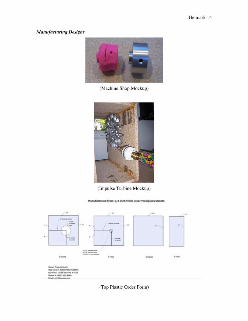
Manufacturing Designs
(Machine Shop Mockup)
(Impulse Turbine Mockup)
(Tap Plastic Order Form)

Heimark 15
Actual Final Model
(Front View)
(Turbine Close-up)
(Side View)

Heimark 16
Final Design
The final design was built with more consideration and attention to detail in order to
minimize resistance and improve overall efficiency.
In contrast to the flat spoons of the earlier proof of concept model, a double
bucket Pelton turbine was purchased from Austria in order to deflect water to the sides
and consequently improve turbine speed. This Pelton turbine was attached to the shaft of
an American Ametek generator; a professionally built generator was substituted for the
homemade generator in order to improve overall output. In order to attach the Pelton
turbine to the turbine, dimensions were taken, a mockup attachment that used screws was
created out of Playdoh (see above), and then a machine shop was used to manufacture the
part.
A cage was then built to house the generator and turbine. First, a mockup was
created out of wood (see above) in order to determine the optimal height for the hose
input; a variety of heights were tried on the wooden mockup using water and a voltmeter
and the optimal height was then determined (i.e. the height at which voltage was
maximized). After creating the mockup and determining the optimal height, dimensions
were taken and a detailed order form was created for tap plastics (see above). Upon the
receipt of the cut plastics, the plastics were attached using plastic cement. Finally, a hole
was drilled so that the hose input, which consisted of a water hose attachment on one end
and a water nozzle on the other end, could be attached to the cage.
After completion of the generator, a water hose could be easily attached to the
generator and the generator could therefore easily produce electricity. Like in the earlier
proof of concept model, the impulse from the water would turn the turbine (which in-turn
would turn the generator) and electricity would be produced.

Heimark 17
Video Final Generator
(YouTube Video Screenshot)
A video of the operational electric motor is available online via YouTube. Please type
http://www.youtube.com/watch?v=sDVQaul_w7/ or http://youtube.com/user/ASRjunkie/
into your web browser.

Heimark 18
IV. Results
Proof of Concept Hydroelectric Generator
(Oscilloscope Electrical Wave Results)
Generator Explanation:
In order to measure the electrical energy produced by the generator model, I employed an
oscilloscope. The oscilloscope graphed a wave, as shown above, based upon the period
and voltage of the electrical output produced by the model. I then utilized the
oscilloscope’s scale to determine the period and voltage of the generator model.
Moreover, I used an ohmmeter to find the resistance of the electrical generator. With
these results and Ohm’s Law (V= I * R), I was able to calculate the current produced. I
could also calculate the power produced using the physics formula for instantaneous
electrical power (P = I * V).
Specifications Sheet:
Peak-To-Peak Height 90 mV
Wave Amplitude 45 mV
Wave Period 20 ms
Wave Frequency 50 Hz
Resistance 11.5 !
Current 0.2 mA
Electrical Power 90 µW

Heimark 19
Calculations:
amplitude = 1/2 * peak to peak = 1/2* 90 mV = 45 mV
frequency = 1/period = 1/(20 * 10^-3 s) = 50 Hz
current I = V/R = (20*10^-3 V)/ 11.5 != 0.2 mA
power = I * V = V^2/R = I^2 * R = (45 * 10^-3 V) * (2 * 10^-3 A) = 90 µW

Heimark 20
Final Hydroelectric Generator
Generator Explanation:
I performed experiments to determine the electrical energy produced by the generator and
its ability to charge a cell phone.
However, I ran into a couple of serious problems. First, the current and voltage in
the Ametek generator are not constant: the produced current and voltage fluctuates with
the strength of the water input (i.e. more water pressure produces more current and more
voltage). Moreover, the electric generator from Ametek has a maximum rating at 38V
even though my hydroelectric generator was able to produce above that voltage when
water hit it.
These problems could have been remedied easily if I had extra funds. Devices that
can accurately measure and/or regulate water pressure are available that cost hundreds (or
thousands) of dollars, money that I did not have available for my experiment. Moreover, I
could purchase a more expensive Ametek generator with a higher rating in order to avoid
overheating. With said equipment, it would have been possible to do several more
experiments with my project.
Considering that I ran out of funding, I used alternative means to avoid these
barriers. First, the highest water pressure available on my hose was used to measure the
electrical energy produced by the generator. The water pressure was held constant at the
maximum pressure while taking measurements for current and voltage in order to ensure
that the values did not fluctuate. Second, because charging a cell phone requires
considerable time (i.e. enough time so that the voltage rating comes into effect if I don’t
want the generator to overheat), the water pressure was set such that approximately 38-
40V was produced before the cell phone was attached.
In order to measure the electrical energy produced by the generator model and
take measurements while charging the cell phone, a combined ammeter/voltmeter was
employed. The ammeter/voltmeter was hooked up in parallel to take voltage
measurements and series to measure current, as required.

Heimark 21
(i) Measuring the Hydroelectric Generator’s Electrical Power
Before any experiments were conducted to measure the hydroelectric generator’s power,
the highest pressure available was set on my hose. Then the resistance of the generator
was taken without significant load (i.e. without a resistor added) in experiment subset
“A”. The current and voltage were measured with the ammeter/voltmeter at that pressure
and resistance. Second, load was added by adding 45 ! of resistance to the circuit in
experiment subset “B”. The current and voltage were then measured again with the
ammeter/voltmeter across the resistors and compared to the original values. The results
were:
Total ResistanceB 47.9 !
Total CurrentB 0.94 A
Total Voltage
DropB 57.2 V
Total PowerB 54 J/s
Figure 1:Measuring the power of the hydroelectric generator. Please note that because
they were series circuits, theoretically: the total current was constant in each resistor;
the resistance was the sum of all resistors; and the total voltage supplied by the battery
was equal to the total voltage drop across the circuit. Moreover, power is equivalent to
the current * voltage.
As shown in Figure 1, it was discovered that the hydroelectric generator produces
upwards of 70 watts of power. However, the power varies with the amount of load (as
well as pressure of the input water). Because the generator still produced significant
power under load, the hydroelectric seems to be capable of handling small electrical
devices.
Total ResistanceA 3.1 !
Total CurrentA 1.36 A
Total Voltage
DropA 56.4 V
Total PowerA 76 J/s

Heimark 22
(ii) Charging a Motorola Razr
Charging my cell phone was also attempted as a scientific experiment. Rather than try to
create my own output, the battery charger was hooked up directly in series to the
hydroelectric generator. In other words, each of the two prongs on the cell phone
transformer that normally would go into a wall was hooked up directly in the circuit.
According to the back of the battery charger, the charger operates when the input
voltage is from 100 – 240 V and the current is 0.3 A (i.e. the power is at least 30 Watts)
and outputs 5 V and 550 mA. Because this voltage is above my capacity, it may seem
impossible for the charger to work directly in series. Surprisingly, the input range appears
to be a recommended range rather than limiting factor; the transformer seems to work
perfectly well below this stated range. Hence hooking up the transformer to my circuit
was still able to charge the battery.
In order to avoid a voltage over the rated threshold (38 V) for a sustained period
of time, the water pressure was changed until approximately 40 V of electricity was
produced. The phone was then attached in series and the current and voltage was
monitored over time. The voltage and current were taken every 15 minutes while the
phone charged. As shown in figure 3, the phone was determined to be charged when the
phone said “charge complete” and still charging when it read “charging battery.” The
results were:
Time (min) Voltage (V) Current (A)
0 38.6 V 0.02 A
15 38.3 V 0.03 A
30 38.5 V 0.01 A
45 37.8 V 0.02 A
60 38.9 V 0.02 A
75 38.5 V 0.02 A
90 38.5 V 0.01 A
105 38.2 V 0.03 A
120 38.6 V 0.01 A
135 38.1 V 0.01 A
Heimark 23
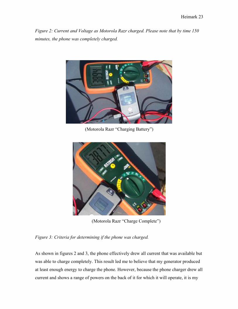
Figure 2: Current and Voltage as Motorola Razr charged. Please note that by time 150
minutes, the phone was completely charged.
(Motorola Razr “Charging Battery”)
(Motorola Razr “Charge Complete”)
Figure 3: Criteria for determining if the phone was charged.
As shown in figures 2 and 3, the phone effectively drew all current that was available but
was able to charge completely. This result led me to believe that my generator produced
at least enough energy to charge the phone. However, because the phone charger drew all
current and shows a range of powers on the back of it for which it will operate, it is my

Heimark 24
conclusion that the phone charger is designed to draw as much current as possible within
its working range in order to charge faster. Hence the phone may charge but the phone
charger takes away all current from the circuit while it charges.
To support my conclusion, the transformer wires were split and tested. The actual
current output on the other end of the transformer was measured to be 363 mA instead of
the labeled 550 mA and 5.07 V instead of 5.0 V. Consequently, because the current was
less than the stated value and the voltage was as stated, it made sense that the voltage
drawn by the cell phone was correct but that the phone continued to try to draw more
input current. Moreover, this discrepancy largely explained the difference in charge-time
between a wall socket (roughly 1.5 hours charge time) and my hydroelectric generator
(measured to be approximately 2.5 hours charge time): because my hydroelectric
generator output less current than a wall socket, it took a proportionally longer amount of
time to charge.

Heimark 25
VI. Conclusion
Through this project, two hydroelectric generators were created that operated quietly,
effectively, and continually. It was shown that water energy may be transformed into
exploitable electric energy using a generator with a rotor and stator. Furthermore, it was
demonstrated that micro to mid-size hydroelectric systems hold great promise in rural
areas where other sources of energy are limited. Systems such as my own system can
produce enough electricity to power small devices and slightly bigger hydroelectric
systems might even have sufficient capacity to handle small villages.
The project as a whole was a great success. Both systems produced electricity,
and the larger system produced far more power than anticipated. According to several
Internet sources, large professional wind-based systems for sale produce slightly fewer
than 200 watts. Based on that relative scale, I am very satisfied with my results of slightly
less than 100 watts (i.e. roughly 75 watts) and my charging time of 2.5 hours. All that
would be required to adapt my system to one’s home is to find a water collection source
where water can build-up or already has high pressure (e.g. collecting rainwater from
your roof or water from your shower). Then one could power lights, cell phones, and
many other devices.
Some experimental errors arose in determining my power output and charging
time and numerous technical errors based upon the accuracy of my equipment. For
instance, the water pressure was never exactly consistent (it is after all a garden hose).
The circuit was also forced to be broken and reconnected every time to switch between
measuring current/voltage even while the phone was being charged. And finally, the
resistors that I used tended to overheat and therefore probably lost some energy to outside
sources (because heat is energy). However, despite these problems, I was still able to
form some sort of conclusion about how much power my device could reasonably output
and what that power could be used for.
Rather than errors with what was performed, my main regrets are experiments
that I was unable to perform due to limited equipment. For instance, because there was no
equipment available that actually measured pressure (I bought something but it didn’t
work effectively), a graph of efficiency or pressure vs. voltage/current was unable to be

Heimark 26
made. Moreover, I was unable to regulate water pressure using professional equipment.
There is some hope that I will be able to perform such experiments in the future at a
college laboratory.
Despite my errors and regrets, my project clearly conveyed the vast implications
of hydroelectric power. Hydroelectric power is already in widespread use due to its
efficacy, but micro hydro systems like my own are becoming ever more popular. Perhaps
one day we won’t just see hydroelectric systems in large government dams: they will
placed in our bathrooms, rainwater gutters, and rivers near our home to provide clean,
powerful electrical energy!

Heimark 27
Bibliography
[1]Rowand Design. “Alternator and Generator Theory.” http://www.rowand.net/. Accessed 4 March 2008. [2]Georgia State University. "Faraday’s Law.” http://hyperphysics.phyastr.gsu.edu/. Accessed 4 March 2008. [3]Tony R. Kuphaldt. Design Science. "Alternating Current." http://www.allaboutcircuits.com/. Accessed 4 March 2008. [4]Edwards, Brian K. The Economics of Hydroelectric Power. N.p.: Edward Elgar, October 2003. [5]ThinkQuest. "Energy Matters: Theory Behind Hydroelectric Power." http://library.thinkquest.org/. Accessed 4 Feb. 2008. [6]BBC. “Three Gorges Dam.” http://www.bbc.co.uk/. Accessed 1 Feb. 2008. [7]"USGS." Hydroelectric Power. US Department of the Interior. http://ga.water.usgs.gov/. Accessed 4 Feb. 2008 [8]“Lester Allan Pelton.” http://www.vermilionohio.org/. Accessed 1 May 2008. [9]“Water wheel.” http://www.silkroadandbeyond.co.uk/images/. Accessed 1 May 2008.