Embed Size (px)
Citation preview

RECon Line
Inverters for Renewable Energies
Power Supply SystemPower Electronics & Automation
FRIEM S.p.A. - Via Edison, 120090 Segrate - Milano - Italy
Tel.: +39 02 87235350 Fax: +39 02 [email protected]
ISO 9001-2008STANDARD
02/2016

FRIEM, leaders in
the fieldToday FRIEM is a group of companies
specialized in electromechanical equipment,
able to provide the best solutions in Industrial,
Traction and Renewable Energies applications.
Content
String InvertersRECon S
Central InvertersRECon Central Inverters
Central Inverters USRECon Central Inverters US
RECon StationRST-RECon Station
AccessoriesSTR-String Box RMS-RECon Monitoring System
Management SystemRECon GC - Generator ControlRECon OGS OFF-GRID Inverter Control
Service and Maintenance
12
34
5
6
12
16
28
32
38
44

In its various facilities FRIEM designs, manufactures and delivers all over the WorldHigh Power Rectifiers and Inverters to meet all of their customers needs.
• AC/DC High Power Rectifiers
• DC/DC High Power Converters
• DC/AC High Power Inverters
• AC/AC High Power Converters
For all the Main Applications
Renewable EnergiesInverters for Photovoltaic plants and Wind turbines
Chemicals ProductionRectifiers and Power Converters for Chlorine, Caustic soda, Chlorate, Hypocloride, Hypochlorine
PolySilicon ProductionPower Supply for CVD Reactors and TET Converters
Heating and GraphitisationRectifiers for Graphite refining furnaces and heating processes
Traction ApplicationRectifiers and Power converters for main DC line Substations
DC Arc Furnaces and Plasma TorchRectifiers and Power Supply for Steel DC Arc Furnaces and Plasma Torch, for stainlesssteel and alloys
Metal refiningRectifiers for Aluminium and Zinc smelters, Copper, Nickel, Lead, Iridium, Indium refineries
3
Know howContinuous investment in research and development
With continuous investment in research and development, FRIEM is leader in Diode, Thyristor or IGBT type High Power Converters, applying the most advanced technologies and electronics.
Our StoryFounded in 1950 to design and manufacture High Power Converters, FRIEM continued to develop its know-how in energy conversion for industrial and traction applications.
In 1956 FRIEM produced and installed its first 50kA Rectifier Unit for application in Chlor-Alkali industry.At the absolute forefront in technology, in the early 60’s FRIEM was able to manufacture units rated up to 110kA and to design the first high current Thyristor Rectifier.
Service continuity required by the Electrochemical Industry oriented FRIEM’s design towards absolutereliability; quality, safety, latest international standards have always been the base for the design anddevelopment of our Equipment.
In the early 70’s when FRIEM started the production of Rectifier Units for traction application. With the support of its Partners, FRIEM provides complete Substations Systems with all the main equipment and services.
In 1984 FRIEM was able to design and start-up its first Power Supply for a PolySilicon CVD Reactor. Nowadays FRIEM has hundreds of units in service all over the World supplying all the different types of CVD Reactors.
In 2009 FRIEM started the production of the RECon Line, a complete line of Inverters for the renewable energies (Photovoltaic Plants and Wind Turbines), becoming one of the main manufacturer in Italy and in the World.
In 2015 has been introduced the RECon HV Line, the 1,500V DC Inverter for the next generation of PV Solar plants.
The new requirements of energy efficiency and cost reduction drove FRIEM to present in 2015 the RECon Line, an IGBT Inverter that allows to recover the energy generated by the train during the braking phase (usually in Subway or Tramway).
2

FRIEM Headquarters
Production Sites (Inverter)
Market Presence
4
5
6
1,2
3. FRIEM, Brasil 5. FRIEM S.A., South Africa 6. L&T, India4. AKTIF, Turkey
5
WorldwideServing the Market with a wider range of products and solutions
COET S.r.l. Founded in 1962 for the production of LV and MV disconnector switches, COET operates nowadays in two main sectors, Industry and Traction, being one of the leading companies for the supply of equipment for Traction Substations. COET joined FRIEM Group in 2008: a new experienced management with the clear and ambitious target to grow the company in the direct export - mainly in Traction field - reaching worldwide the same leader position held in Italy for decades.
AKTIF Elektroteknik The company was established to manufacture Switchgears and Kiosks in 1981. In 2008 merged to Aktif Group as Aktif Elektroteknik (AET) and then became an international co. after significant participation of FRIEM in 2009. AET operates with its 30 years of manufacturing experience, modernized machinery line, ever increasing know-how, experienced Turkish and Italian R&D teams, quality products type tested by the leading accredited European laboratories and the vision of new ideas to meet with the future expectations.
In 2012 FRIEM started to broaden its own production founding FRIEM Conversores Ltd based in San Paolo (Brazil) and then, in 2014, FRIEM South Africa based in Cape Town. As a result, customers can rely on the quality and performance of FRIEM’s products, with the advantage of a local production and after-sales assistance. To address these important requirements in the Indian market, FRIEM signed in 2014 a License agreement with L&T - C&A (Larsen and Toubro Control and Automation) for the local production and distribution of the RECon Line Inverters in India.This represents for FRIEM a further step towards its continuously growing international expansion and an outstanding accomplishment in the field of Industrial and Renewable energy Inverters.
The strategy of making FRIEM’s local presence stronger also counts nowadays with offices and representatives in more than 20 Countries all over the World.
3
1. FRIEM, Italy 2. COET, Italy
4
FRIEM GROUP

T = 25 degC, Irr. (rated %) = 25.0, 50.0, 75.0, 100
4
3.5
3
2.5
2
1.5
1
0.5
0
Curr
ent (
A)
0 5 10 15 20 25Voltage (V)
2000
1800
1600
1400
1200
1000
800
600
400
200
0
Pow
er (W
)
0 50 100 150 200 250 300 350Tension (V)
Maximum
Maximum
Maximum Power Point TrackingThe Characteristics of photovoltaic panels are not stable, in fact they vary in function of weather conditions and solar irradiation.
The purpose of the MPPT System is to follow the maximum power point for any photovoltaic module.Analyzing the V-P solar panel characteristic, it can be noticed that, when environmental conditions change(partial shading of the panels), there exists different absolute and relative maximum power points.
The MPPT controls the voltage, current and power of the photovoltaic field and generates the Reference Current for the Current Regulator of the Inverter to achieve the greatest possible power harvest.The MPPT algorithm sample the output of the photovoltaic panel, to obtain the Maximum Power for any given environmental condition.The calculated voltage at which the photovoltaic panel should work is based on the voltage measurement of the panel and from the supplied Power.
The two most common methods to execute the MPPT algorithm are: - Incremental Conductance (IncCon).- Perturb and Observe (P&O).
The RECon Line Inverters use both algorithms.
Initial FV CharacteristicFinal FV CharacteristicMPPT FV Characteristic
7
Our SolutionsTailor made solutions for your needs
FRIEM has developed a complete line of high power Solar Inverters for small and big plants, residential, commercial and utility scale.
RECon LineThe RECon Line concept is derived from the long experience FRIEM has achieved in Power Conversion and in the use of all kind of semiconductors.
The Line has been developed following FRIEM’s traditional concept of reliability, efficiency and modularity devoted to high flexibility and easy maintenance.
All the models can be either used as single units or combined in parallel to reach the requested power.The different models of RECon Line Inverters are available in three main versions:
RECon SSingle Phase and Three Phase String Inverters.Especially designed mainly for commercial and residential use, both indoor and outdoor.
RECon Central Inverters - Non residential Three-phase Central Inverter with external LV/MV transformer. Thanks to the wide range of models, they can be employed in medium and large photovoltaic fields.
RECon RST Line - Utility Scale Complete turn-key solution for utility scale photovoltaic plants.
The RECon Line Inverters offer: • Modular draw-out and Compact Design for
configuration flexibility, space saving and fast installation. • Parallel Modules or Independent Modules
Configurations. • Easy Maintenance thanks to the completely
withdrawable Power Section. • The Digital Regulator FRIEM DRP-6Ph Type allows
the fully automated Control and Protection of the Inverter itself and offers the availability of: - Single or Multiple MPPT management. - Real Time and Recorded Measurements. - Event Recording, Load Profile and Oscyllography. - Internal Canbus Communication Protocol for I/O management (temperature, irradiation and wind speed sensors). - Programmable Output Relays, Digital Inputs and Outputs. - Comprehensive self diagnostic - not just memory checksums - periodically tests the entire regulator. • A Touch Screen Operator Panel for easy access to
Measurements and Setting Parameters of one or more Inverters and of the PV Field, equipped with: - Front Face USB Serial Comm. Port for Local Interface. - Second Serial RS485 Comm. Port. - RS232/Modem Comm. Port. - Ethernet Serial Comm. Port. • A Standard Modbus TCP/IP communication protocols. • Conformance to IEC Standards and CE Directive;
UL-CSA listed. • ISO 9001: 2008 Certified Quality System.
6

Inverter Applicable StandardsMV Connection2004/108/EC EMC - Electromagnetic Compatibility2006/95/ECLow Voltage DirectiveSafetyEN-62109-1 : 2010-12Safety for Power Converter for use in Photovoltaic Power Systems-General RequirementsEN-62109-2 : 2012-04Safety of Power Converter for use in Photovoltaic Power Systems-Particular Requirements for InvertersIEC60730-1Automatic electrical controls for household and similar use- Part 1General requirementsSemiconductor convertorIEC 60146 - 1 - 1: 2009 - 06Semiconductor convertorsGeneral requirements and line commutated convertors- Part 1.1Specifications of basic requirementsEN 60146-1-3: 1997 - 09Semiconductor convertorsGeneral requirements and line commutated convertors- Part 1.3Specifications of basic requirementsElectrical energy production systemCEI 11-20: 2000 + V1: 2004Electrical energy production system and uninterruptablepower systems connected to I and II class networkDistribution HV - MV NetworkCEI 0-16: 2012-12 ED.III var.1Reference technical rules for the connection of activeand passive consumers to the HV and MV electricalnetworks of distribution CompanySAGC2.6South African Grid Code ver. 2.6Ordinul Nr.30 din 17.05.2013 Technical condition for connection to public electrical grids of photovoltaic power plantsPEAERC Rules and Regulation on Thailand’s Solar Rooftop Programme. The requirements on Grid Connection of Provincial Electricity Authority.EMCImmunità / ImmunityEN 61000 - 6 - 2: 2005Electromagnetic compatibility (EMC) - Part 6-2Generic standards - Immunity for industrial environmentsEmissionEN 61000 - 6 - 4: 2007Electromagnetic compatibility (EMC) - Part 6-4Generic standards - Emission standard for industrialenvironments
EUROPEAN EFFICIENCY EVALUATIONIEC 61683: 1999-11Photovoltaic Systems - Power Conditioner- Procedure for measuring efficiencyIEC 62116: 2014 (ed.2.0)Utility-interconnected photovoltaic inverters- Test procedure of islanding prevention measures.
LV ConnectionThe same as MV except CEI 0-16 and EmissionEN 61000-6-4EmissionEN 61000 - 6 - 3: 2007-11Electromagnetic compatibility (EMC) - Part 6-3Generic standards - Emission standard for residential, commercial and light-industrial environments
RECon 30 L/H - USUL1741Inverter, Converter, Controllers and Interconnection SystemEquipment for use with Distributed Energy ResourcesIEEE 1547Standard for Interconnecting Distributed Resourcewith Electrical Power SystemCSA C.22.2 No. 107.1-01General Use Power SupplyANSI.C84.1-1995 (R2005)Electrical Power System and Equipment-Voltage Rating (60 Hertz)NEMA 250Enclosures for Electrical Equipment (1000V Maximum)NFPA 70 National Electrical Code 2011CEC Guideline for the use of the Performance Test Protocol for Evaluating Inverters Used in Grid-Connected Photovoltaic Systems
RECon S1 and S3Distribution LV networkCEI 0-21: 2012-12 + V1 2012-12Reference technical rules for the connection of activeand passive users to the LV electrical UtilitiesVDE-AR-N 4105:2011-08Reference technical rules for the connection of activeand passive users to the LV electrical UtilitiesNRS 097-2-1:2010Grid Interconnection of embedded generationPart 2: Small-scale embedded generation - Section 1: utility interface.
9
Output Efficiency CurveThe graph here below shows the efficiency load curve of the RECon-line Inverters.The efficiency reaches not only very high absolute values (ηmax 99,7% @ 0,9 Pn), but also stays above 98%, starting from the 20% of the load, granting a high EURO efficiency.
OutputEfficiencyatOperatingVoltage CECOutputEfficiency
110,0%
100,0%
90,0%
80,0%
70,0%
60,0%
50,0%
100
95
85
80
75
70
Out
put E
ffici
ency
Out
put E
ffici
ency
0,0 20,0 40,0 60,0 80,0 100,0 120,0 0% 10% 20% 30% 40% 50% 60% 70% 80% 90% 100%
Rated Load % Rated Load %
Maximum Output Efficiency
99,3%*
EURO Output Efficiency
98,8%*
CEC Output Efficiency
99%**
No-load loss 35W
Stand-by loss 50W
When an efficiency value has been guaranteed, the tolerance of this value shall be within the value at rated conditions indicated below:-0,2 x (1-η) x h (%)(h=guaranteed efficiency)
* referred to the RECon 30H Line** referred to the RECon 2.30H1 Line
8

5
3
4
RECon Management System p.38
RST RECon Station - Utility Scale p.28
Accessories p.32
RECon GC RECon OGC
RST Line252 - 4400 kWp
STR - String Box RMS - Remote Monitoring System
11
Our Products
1
2
RECon S: String Inverters p.12
RECon Central Inverters - Non residential p.16
RECon Central Inverters US - Non residential
RECon S1 2.5-5 kW AC
RECon 30L/30H/30L1/30H1 LineSingle module up to 6 modules
RECon 30L 100-600 kW ACRECon 30L1 125-750 kW ACRECon 30H 150-900 kW ACRECon 30H1@330V 167-1002 kW ACRECon 30H1@375V 193-1155 kW ACRECon 30H1@400V 204-1227 kW AC
RECon 30L/30H/30L1/30H1 US LineSingle module up to 6 modules
RECon 30L 100-600 kW ACRECon 30H 150-900 kW ACRECon 30H1@330V 167-1002 kW AC
RECon 2.30H/2.30H1 LineSingle module up to 3 modules
RECon 2.30H 300-900 kW ACRECon 2.30H1@330V 334-1002 kW ACRECon 2.30H1@375V 385-1155 kW ACRECon 2.30H1@400V 409-1227 kW AC
RECon 2.30H/2.30H1 US LineSingle module up to 3 modules
RECon 2.30H1@400V 409-1227 kW AC
RECon S3 10-20 kW AC
10

The “string inverters” have been developed to complete our range of products, granting a wide range of Inverters (from 2.5kW to 20kW).
Our RECon S String Inverters are available in two different models Single Phase (S1) and Three Phase (S3).
The RECon S Line has been especially designed mainly for commercial and residential use, both indoor and outdoor. The Inverters include a communication port RS485 Modbus and Bluetooth on request. Display data is simple and clear and available in different languages. Also the setting of the parameters is simple thanks to the 4-button keypad.
All the different models of the RECon - S have been tested and certified according to VDE and IEC standards.
1
RECo
n S
- Str
ing
Inve
rter
s
13
String InvertersRECon S
12
RECon S3 10 12 15 20
Input (DC) Max. input power DC kWp 10.35 12.45 15.55 20.6 Max. input voltage in open circuit V 1000 Max. input current A 20 MPPT range V 250-800 330-800 380-800 450-800 Number of MPPT trackers - 2
Output (AC) Rated output power AC kW 10 12 15 20 Rated output voltage V 400 Frequency Hz 50 / 60 Max. output power A 15 18 22 29 Total harmonic distortion % < 3 Efficiency Maximum efficiency % 98 98 98 98.2 EURO Efficiency % 97.3 97.3 97.4 97.5
Mechanical details Dimension (WxHxD) mm 550x650x250 550x650x250 550x650x250 550x650x250 Weight kg 45 45 50 55 Protection class - IP 65 Temperature Operating temperature range °C . -25 ÷ + 60
General data Night consumption W < 1 DC connections - MC4 AC connection - Plug Noise dB < 50
Interfaces Local user interface - Graphic display Communication - RS485 Modbus / Bluetooth (optional)
Standards & certifications EMC - Yes CE conformity - Yes Standard warranty - 10 Years Standards - VDE 4105 / NRS 097-2-1
RECon S3 Line
15
RECon S1 2.5 3 3.6 4 4.6 5
Input (DC) Max. input power DC kWp 2.7 3.2 3.8 4.3 4.8 5.2 Max. input voltage in open circuit V 500 550 600 550 600 550 Max. input current A 13.5 15 15 15 15 15 MPPT range V 180-400 200-480 200-480 200-480 200-480 200-480 Number of MPPT trackers - 2
Output (AC) Rated output power AC kW 2.5 3 3.6 4 4.6 5 Rated output voltage V 230 Frequency Hz 50 / 60 Max. output power A 12.5 16 18 21 23 25 Total harmonic distortion % < 3
Efficiency Maximum efficiency % 96.7 97 97 97.5 97.5 97.5 EURO Efficiency % 95.5 96 96 97 97 97
Mechanical details Dimension (WxHxD) mm 380x498x145 398x485x187 398x485x187 398x485x187 398x485x187 398x485x187 Weight kg 15 23.5 23.5 23.5 23.5 23.5 Protection class - IP 65
Temperature Operating temperature range °C . -25 ÷ + 60
General data Night consumption W < 0,2 DC connections - MC4 AC connection - Plug Noise dB < 30
Interfaces Local user interface - Touch screen display Communication - RS485 Modbus / Bluetooth (optional) Standards & certifications EMC - Yes CE conformity - Yes Standard warranty - 7 Years Standards - VDE 4105 / CEI 0-21 / NRS 097-2-1
RECon S1 Line
14

The Central Inverters are the first born and represent the flagship of RECon Line.
The line has been developed following FRIEM’s traditional concepts of reliability, efficiency and modularity, devoted to high flexibility and easy maintenance.
Our RECon Central Inverters have modular and compact design; they can be used as single unit or combined in parallel to reach the requested power. From one single module up to six modules, starting from 100kWp up to 1470kWp, with 100% independent operation of each module.
Thanks to the modularity, each Inverter can manage more than one independent subfield with different irradiation and exposition, with multiple MPPTs (up to 6 MPPTs for MW A.C.).
Fully automated Regulation performing, Control and Protection, highest conversion efficiency, standard Modbus-RTU communication protocols and a touch screen operator panel, are definitively value added features.
With 20 years life design, and industrial design suitable for hard environments, FRIEM’s Inverters ensure easy maintenance and quick replacement of the main components, granting the possibility of easy onsite maintenance and simplified spare parts management. The complete Removable Inverter Board can be replaced in only 1 hour, ensuring full reliability and continuity of production.
All the different models of the RECon Line have been tested and certified according to IEC Standards and CE Directive, UL and CEC.
All the RECon Line Central Inverters are available in “US Version”, especially made for US Market.
2
RECo
n - C
entr
al In
vert
ers
17
Central InvertersRECon
16

RECon 30L1 125 250 375 500 625 750
Input (DC) Suggested peak power kWp 156 313 469 625 781 938 Rated input current A 325 650 975 1300 1625 1950 Max. input voltage in open circuit V 800 MPPT range V 392 - 680 Number of MPPT trackers - 1 2 3 4 5 6
Output (AC) Rated output voltage V 250 Frequency Hz 50 / 60 Rated power kW 125 250 375 500 625 750 Rated Apparent power kVA 132 264 396 528 660 792 Rated current A 295 590 885 1180 1475 1770 Power factor - rated - > 0,99 at rated power (0,9 Lead to 0,9 Lag) Total harmonic distortion % < 3
Auxiliary power Auxiliary supply from UPS V 230 (110 US-Line) Auxiliary supply voltage range V 195 - 253 (106 - 126 US-Line) Standby consumption W 50 100 150 200 250 300
Efficiency Maximum efficiency % 99 EURO Efficiency % 98.1 CEC Efficiency % 98
Mechanical details Dimension (WxHxD) mm 550x2200x800 1100x2200x800 1650x2200x800 2200x2200x800 2750x2200x800 3300x2200x800
Weight kg 500 1000 1500 2000 2500 3000 Protection class - IP 20
Temperature Operating temperature range °C . -10°C/ + 55°C (*)
Protection and monitoring Array grounding configuration - Negative grounded / Positive grounded / Floating Array ground fault protection - Isolation monitor
Interfaces Local user interface - Touch screen display String-Box communication port - RS485 Modbus PC communication port - RS232 - RS485 - USB Remote communication port - Ethernet
Standards & certifications Product standard - 2004/108/EC - 2006/95/EC - CEI EN 62109-1 (2010) - CEI EN 62109-2 (2012) - IEC60730 (2010)
Grid requirements - CEI 0-16 ED. III (2012) - IEC62116 - SAGC2.6 - IEEE1547 (2003) - IEEE1547.1 (2005): Thailand; Brazil
EMC - EN 61000 - 6 - 2 / EN 61000 - 6 - 4 / FCC Euro Efficiency - IEC 61683: 1999-11 Power management functions - LVRT, Power factor Control, Grid Fault Support, Power / Frequency Control and Ramp Rate
*no de-rating up to 45°C ; 1,5% de-rating per degree in temperature from 45°
RECon 30L1 Line
19
RECon 30L/30L-US 100 200 300 400 500 600
Input (DC) Suggested peak power kWp 125 250 375 500 625 750 Rated input current A 325 650 975 1300 1625 1950 Max. input voltage in open circuit V 700 MPPT range V 325 - 680 Number of MPPT trackers - 1 2 3 4 5 6
Output (AC) Rated output voltage V 200 Frequency Hz 50 / 60 Rated power kW 100 200 300 400 500 600 Rated Apparent power kVA 105 210 315 420 525 630 Rated current A 295 590 885 1180 1475 1770 Power factor - rated - > 0,99 at rated power (0,9 Lead to 0,9 Lag) Total harmonic distortion % < 3
Auxiliary power Auxiliary supply from UPS V 230 (110 US-Line) Auxiliary supply voltage range V 195 - 253 (106 - 126 US-Line) Standby consumption W 50 100 150 200 250 300
Efficiency Maximum efficiency % 99 EURO Efficiency % 98.1 CEC Efficiency % 98
Mechanical details Dimension (WxHxD) mm 550x2200x800 1100x2200x800 1650x2200x800 2200x2200x800 2750x2200x800 3300x2200x800
Dimension (WxHxD) US-Line mm 590x2282x1208 1140x2282x1208 1690x2282x1208 2240x2282x1208 2790x2282x1208 3340x2282x1208
Weight kg 500 1000 1500 2000 2500 3000 Protection class - IP 20 / NEMA 3R
Temperature Operating temperature range °C . -10°C/ + 55°C (*)
Protection and monitoring Array grounding configuration - Negative grounded / Positive grounded / Floating Array ground fault protection - Isolation monitor
Interfaces Local user interface - Touch screen display String-Box communication port - RS485 Modbus PC communication port - RS232 - RS485 - USB Remote communication port - Ethernet
Standards & certifications Product standard - 2004/108/EC - 2006/95/EC - CEI EN 62109-1 (2010) - CEI EN 62109-2 (2012) - IEC60730 (2010) - UL1741 (2010) - CSA C22.2 No. 107.1-01 (2011)
Grid requirements - CEI 0-16 ED. III (2012) - IEC62116 - SAGC2.6 - IEEE1547 (2003) - IEEE1547.1 (2005): Thailand; Brazil
EMC - EN 61000 - 6 - 2 / EN 61000 - 6 - 4 / FCC Euro Efficiency - IEC 61683: 1999-11 Power management functions - LVRT, Power factor Control, Grid Fault Support, Power / Frequency Control and Ramp Rate
*no de-rating up to 45°C ; 1,5% de-rating per degree in temperature from 45°
RECon 30L/30L-US Line
18

RECon 30H1 167 334 501 668 835 1002
Input (DC) Suggested peak power kWp 202 404 606 808 1010 1212 Rated input current A 325 650 975 1300 1625 1950 Max. input voltage in open circuit V 1000 MPPT range V 518 - 885 Number of MPPT trackers - 1 2 3 4 5 6
Output (AC) Rated output voltage V 330 Frequency Hz 50 / 60 Rated power kW 167 334 501 668 835 1002 Rated Apparent power kVA 176 352 527 703 879 1055 Rated current A 295 590 885 1180 1475 1770 Power factor - rated - > 0,99 at rated power (0,9 Lead to 0,9 Lag) Total harmonic distortion % < 3
Auxiliary power Auxiliary supply from UPS V 230 Auxiliary supply voltage range V 195 - 253 Standby consumption W 50 100 150 200 250 300
Efficiency Maximum efficiency % 99.3 EURO Efficiency % 98.7 CEC Efficiency % 98
Mechanical details Dimension (WxHxD) mm 550x2200x800 1100x2200x800 1650x2200x800 2200x2200x800 2750x2200x800 3300x2200x800
Weight kg 500 1000 1500 2000 2500 3000 Protection class - IP 20
Temperature Operating temperature range °C . -10°C/ + 55°C (*)
Protection and monitoring Array grounding configuration - Negative grounded / Positive grounded / Floating Array ground fault protection - Isolation monitor
Interfaces Local user interface - Touch screen display String-Box communication port - RS485 Modbus PC communication port - RS232 - RS485 - USB Remote communication port - Ethernet
Standards & certifications Product standard - 2004/108/EC - 2006/95/EC - CEI EN 62109-1 (2010) - CEI EN 62109-2 (2012) - IEC60730 (2010)
Grid requirements - CEI 0-16 ED. III (2012) - IEC62116 - SAGC2.6 - IEEE1547 (2003) - IEEE1547.1 (2005): Thailand; Brazil
EMC - EN 61000 - 6 - 2 / EN 61000 - 6 - 4 / FCC Euro Efficiency - IEC 61683: 1999-11 Power management functions - LVRT, Power factor Control, Grid Fault Support, Power / Frequency Control and Ramp Rate
*no de-rating up to 45°C ; 1,5% de-rating per degree in temperature from 45°
RECon 30H1 Line
21
RECon 30H/30H-US 150 300 450 600 750 900
Input (DC) Suggested peak power kWp 188 375 563 750 938 1125 Rated input current A 325 650 975 1300 1625 1950 Max. input voltage in open circuit V 900 MPPT range V 480 - 885 Number of MPPT trackers - 1 2 3 4 5 6
Output (AC) Rated output voltage V 300 Frequency Hz 50 / 60 Rated power kW 150 300 450 600 750 900 Rated Apparent power kVA 158 316 474 632 789 947 Rated current A 295 590 885 1180 1475 1770 Power factor - rated - > 0,99 at rated power (0,9 Lead to 0,9 Lag) Total harmonic distortion % < 3
Auxiliary power Auxiliary supply from UPS V 230 Auxiliary supply voltage range V 195 - 253 Standby consumption W 50 100 150 200 250 300
Efficiency Maximum efficiency % 99.3 EURO Efficiency % 98.7 CEC Efficiency % 98
Mechanical details Dimension (WxHxD) mm 550x2200x800 1100x2200x800 1650x2200x800 2200x2200x800 2750x2200x800 3300x2200x800
Dimension (WxHxD) US-Line mm 590x2282x1208 1140x2282x1208 1690x2282x1208 2240x2282x1208 2790x2282x1208 3340x2282x1208
Weight kg 500 1000 1500 2000 2500 3000 Protection class - IP 20 / NEMA 3R
Temperature Operating temperature range °C . -10°C/ + 55°C (*)
Protection and monitoring Array grounding configuration - Negative grounded / Positive grounded / Floating Array ground fault protection - Isolation monitor
Interfaces Local user interface - Touch screen display String-Box communication port - RS485 Modbus PC communication port - RS232 - RS485 - USB Remote communication port - Ethernet
Standards & certifications Product standard - 2004/108/EC - 2006/95/EC - CEI EN 62109-1 (2010) - CEI EN 62109-2 (2012) - IEC60730 (2010) - UL1741 (2010) - UL1998 (2008) - CSA C22.2 No. 107.1-01 (2011)
Grid requirements - CEI 0-16 ED. III (2012) - IEC62116 - SAGC2.6 - IEEE1547 (2003) - IEEE1547.1 (2005): Thailand; Brazil
EMC - EN 61000 - 6 - 2 / EN 61000 - 6 - 4 / FCC Euro Efficiency - IEC 61683: 1999-11 Power management functions - LVRT, Power factor Control, Grid Fault Support, Power / Frequency Control and Ramp Rate
*no de-rating up to 45°C ; 1,5% de-rating per degree in temperature from 45°
RECon 30H/30H-US Line
20

RECon 30H1 @ 400V 204 409 613 817 1021 1227
Input (DC) Suggested peak power kWp 245 490 735 980 1225 1470 Rated input current A 325 650 975 1300 1625 1950 Max. input voltage in open circuit V 1000 MPPT range V 610 - 885 Number of MPPT trackers - 1 2 3 4 5 6
Output (AC) Rated output voltage V 400 Frequency Hz 50 / 60 Rated power kW 204.5 409 613.5 818 1022.5 1227 Rated Apparent power kVA 215 431 646 861 1076 1292 Rated current A 295 590 885 1180 1475 1770 Power factor - rated - > 0,99 at rated power (0,9 Lead to 0,9 Lag) Total harmonic distortion % < 3
Auxiliary power Auxiliary supply from UPS V 230 Auxiliary supply voltage range V 195 - 253 Standby consumption W 50 100 150 200 250 300
Efficiency Maximum efficiency % 99.3 EURO Efficiency % 98.7 CEC Efficiency % 98
Mechanical details Dimension (WxHxD) mm 550x2200x800 1100x2200x800 1650x2200x800 2200x2200x800 2750x2200x800 3300x2200x800
Weight kg 500 1000 1500 2000 2500 3000 Protection class - IP 20
Temperature Operating temperature range °C . -10°C/ + 55°C (*)
Protection and monitoring Array grounding configuration - Negative grounded / Positive grounded / Floating Array ground fault protection - Isolation monitor
Interfaces Local user interface - Touch screen display String-Box communication port - RS485 Modbus PC communication port - RS232 - RS485 - USB Remote communication port - Ethernet
Standards & certifications Product standard - 2004/108/EC - 2006/95/EC - CEI EN 62109-1 (2010) - CEI EN 62109-2 (2012) - IEC60730 (2010)
Grid requirements - CEI 0-16 ED. III (2012) - IEC62116 - SAGC2.6 - IEEE1547 (2003) - IEEE1547.1 (2005) EMC - EN 61000 - 6 - 2 / EN 61000 - 6 - 4 / FCC Euro Efficiency - IEC 61683: 1999-11 Power management functions - LVRT, Power factor Control, Grid Fault Support, Power / Frequency Control and Ramp Rate
*no de-rating up to 45°C ; 1,5% de-rating per degree in temperature from 45°
RECon 30H1 Line @ 400V
23
RECon 30H1 @ 375V 193 385 578 770 963 1155
Input (DC) Suggested peak power kWp 241 481 723 963 1204 1444 Rated input current A 325 650 975 1300 1625 1950 Max. input voltage in open circuit V 1000 MPPT range V 565 - 885 Number of MPPT trackers - 1 2 3 4 5 6
Output (AC) Rated output voltage V 375 Frequency Hz 50 / 60 Rated power kW 191.5 383 574.5 766 957.5 1149 Rated Apparent power kVA 202 403 605 806 1008 1209 Rated current A 295 590 885 1180 1475 1770 Power factor - rated - > 0,99 at rated power (0,9 Lead to 0,9 Lag) Total harmonic distortion % < 3
Auxiliary power Auxiliary supply from UPS V 230 Auxiliary supply voltage range V 195 - 253 Standby consumption W 50 100 150 200 250 300
Efficiency Maximum efficiency % 99.3 EURO Efficiency % 98.7 CEC Efficiency % 98
Mechanical details Dimension (WxHxD) mm 550x2200x800 1100x2200x800 1650x2200x800 2200x2200x800 2750x2200x800 3300x2200x800
Weight kg 500 1000 1500 2000 2500 3000 Protection class - IP 20
Temperature Operating temperature range °C . -10°C/ + 55°C (*)
Protection and monitoring Array grounding configuration - Negative grounded / Positive grounded / Floating Array ground fault protection - Isolation monitor
Interfaces Local user interface - Touch screen display String-Box communication port - RS485 Modbus PC communication port - RS232 - RS485 - USB Remote communication port - Ethernet
Standards & certifications Product standard - 2004/108/EC - 2006/95/EC - CEI EN 62109-1 (2010) - CEI EN 62109-2 (2012) - IEC60730 (2010)
Grid requirements - CEI 0-16 ED. III (2012) - IEC62116 - SAGC2.6 - IEEE1547 (2003) - IEEE1547.1 (2005) EMC - EN 61000 - 6 - 2 / EN 61000 - 6 - 4 / FCC Euro Efficiency - IEC 61683: 1999-11 Power management functions - LVRT, Power factor Control, Grid Fault Support, Power / Frequency Control and Ramp Rate
*no de-rating up to 45°C ; 1,5% de-rating per degree in temperature from 45°
RECon 30H1 Line @ 375V
22

RECon 2.30H1 334 668 1002
Input (DC) Suggested peak power kWp 404 808 1212 Rated input current A 650 1300 1950 Max. input voltage in open circuit V 1000 MPPT range V 518 - 885 Number of MPPT trackers - 1 2 3
Output (AC) Rated output voltage V 330 Frequency Hz 50 / 60 Rated power kW 334 668 1002 Rated Apparent power kVA 352 703 1055 Rated current A 590 1180 1770 Power factor - rated - > 0,99 at rated power (0,9 Lead to 0,9 Lag) Total harmonic distortion % < 3 Auxiliary power Auxiliary supply from UPS V 230 Auxiliary supply voltage range V 195 - 253 Standby consumption W 50 100 150
Efficiency Maximum efficiency % 99.2 EURO Efficiency % 98.8 CEC Efficiency % 99 Mechanical details Dimension (WxHxD) mm 1100x2200x800 2200x2200x800 3300x2200x800
Weight kg 750 1500 2250 Protection class - IP 20
Temperature Operating temperature range °C . -10°C/ + 55°C (*)
Protection and monitoring Array grounding configuration - Negative grounded / Positive grounded / Floating Array ground fault protection - Isolation monitor
Interfaces Local user interface - Touch screen display String-Box communication port - RS485 Modbus PC communication port - RS232 - RS485 - USB Remote communication port - Ethernet
Standards & certifications Product standard - 2004/108/EC - 2006/95/EC - CEI EN 62109-1 (2010) - CEI EN 62109-2 (2012) - IEC60730 (2010)
Grid requirements - CEI 0-16 ED. III (2012) - IEC62116 - SAGC2.6 - IEEE1547 (2003) - IEEE1547.1 (2005): Thailand; Brazil
EMC - EN 61000 - 6 - 2 / EN 61000 - 6 - 4 / FCC Euro Efficiency - IEC 61683: 1999-11 Power management functions - LVRT, Power factor Control, Grid Fault Support, Power / Frequency Control and Ramp Rate
*no de-rating up to 45°C ; 1,5% de-rating per degree in temperature from 45°
RECon 2.30H1 Line
25
RECon 2.30H 300 600 900
Input (DC) Suggested peak power kWp 362 724 1086 Rated input current A 650 1300 1950 Max. input voltage in open circuit V 900 MPPT range V 480 - 885 Number of MPPT trackers - 1 2 3
Output (AC) Rated output voltage V 300 Frequency Hz 50 / 60 Rated power kW 300 600 900 Rated Apparent power kVA 316 632 947 Rated current A 590 1180 1770 Power factor - rated - > 0,99 at rated power (0,9 Lead to 0,9 Lag) Total harmonic distortion % < 3
Auxiliary power Auxiliary supply from UPS V 230 Auxiliary supply voltage range V 195 - 253 Standby consumption W 50 100 150
Efficiency Maximum efficiency % 99.2 EURO Efficiency % 98.8 CEC Efficiency % 99 Mechanical details Dimension (WxHxD) mm 1100x2200x800 2200x2200x800 3300x2200x800
Weight kg 750 1500 2250 Protection class - IP 20
Temperature Operating temperature range °C . -10°C/ + 55°C (*)
Protection and monitoring Array grounding configuration - Negative grounded / Positive grounded / Floating Array ground fault protection - Isolation monitor
Interfaces Local user interface - Touch screen display String-Box communication port - RS485 Modbus PC communication port - RS232 - RS485 - USB Remote communication port - Ethernet
Standards & certifications Product standard - 2004/108/EC - 2006/95/EC - CEI EN 62109-1 (2010) - CEI EN 62109-2 (2012) - IEC60730 (2010)
Grid requirements - CEI 0-16 ED. III (2012) - IEC62116 - SAGC2.6 - IEEE1547 (2003) - IEEE1547.1 (2005): Thailand; Brazil
EMC - EN 61000 - 6 - 2 / EN 61000 - 6 - 4 / FCC Euro Efficiency - IEC 61683: 1999-11 Power management functions - LVRT, Power factor Control, Grid Fault Support, Power / Frequency Control and Ramp Rate
*no de-rating up to 45°C ; 1,5% de-rating per degree in temperature from 45°
RECon 2.30H Line
24
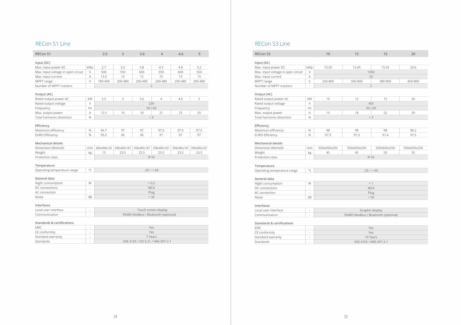
RECon 2.30H1 @ 400V 409 818 999** 1227
Input (DC) Suggested peak power kWp 490 980 1225 1470 Rated input current A 650 1300 1625 1950 Max. input voltage in open circuit V 1000 MPPT range V 610 - 885 Number of MPPT trackers - 1 2 3 3
Output (AC) Rated output voltage V 400 Frequency Hz 50 / 60 Rated power kW 409 818 999 1227 Rated Apparent power kVA 431 861 999 1292 Rated current A 590 1180 1475 1770 Power factor - rated - > 0,99 at rated power (0,9 Lead to 0,9 Lag) Total harmonic distortion % < 3 Auxiliary power Auxiliary supply from UPS V 230 Auxiliary supply voltage range V 195 - 253 Standby consumption W 50 100 125 150
Efficiency Maximum efficiency % 99.2 EURO Efficiency % 98.8 CEC Efficiency % 99 Mechanical details Dimension (WxHxD) mm 1100x2200x800 2200x2200x800 2750x2200x800 3300x2200x800
Weight kg 750 1500 1875 2250 Protection class - IP 20
Temperature Operating temperature range °C . -10°C/ + 55°C (*)
Protection and monitoring Array grounding configuration - Negative grounded / Positive grounded / Floating Array ground fault protection - Isolation monitor
Interfaces Local user interface - Touch screen display String-Box communication port - RS485 Modbus PC communication port - RS232 - RS485 - USB Remote communication port - Ethernet
Standards & certifications Product standard - 2004/108/EC - 2006/95/EC - CEI EN 62109-1 (2010) - CEI EN 62109-2 (2012) - IEC60730 (2010)
Grid requirements - CEI 0-16 ED. III (2012) - IEC62116 - SAGC2.6 - IEEE1547 (2003) - IEEE1547.1 (2005) EMC - EN 61000 - 6 - 2 / EN 61000 - 6 - 4 / FCC Euro Efficiency - IEC 61683: 1999-11 Power management functions - LVRT, Power factor Control, Grid Fault Support, Power / Frequency Control and Ramp Rate
*no de-rating up to 45°C ; 1,5% de-rating per degree in temperature from 45°** available only for Turkish market
RECon 2.30H1 Line @ 400V
27
RECon 2.30H1 @ 375V 385 770 1155
Input (DC) Suggested peak power kWp 490 980 1470 Rated input current A 650 1300 1950 Max. input voltage in open circuit V 1000 MPPT range V 565 - 885 Number of MPPT trackers - 1 2 3
Output (AC) Rated output voltage V 375 Frequency Hz 50 / 60 Rated power kW 383 766 1149 Rated Apparent power kVA 403 806 1209 Rated current A 590 1180 1770 Power factor - rated - > 0,99 at rated power (0,9 Lead to 0,9 Lag) Total harmonic distortion % < 3 Auxiliary power Auxiliary supply from UPS V 230 Auxiliary supply voltage range V 195 - 253 Standby consumption W 50 100 150
Efficiency Maximum efficiency % 99.2 EURO Efficiency % 98.8 CEC Efficiency % 99 Mechanical details Dimension (WxHxD) mm 1100x2200x800 2200x2200x800 3300x2200x800
Weight kg 750 1500 2250 Protection class - IP 20
Temperature Operating temperature range °C . -10°C/ + 55°C (*)
Protection and monitoring Array grounding configuration - Negative grounded / Positive grounded / Floating Array ground fault protection - Isolation monitor
Interfaces Local user interface - Touch screen display String-Box communication port - RS485 Modbus PC communication port - RS232 - RS485 - USB Remote communication port - Ethernet
Standards & certifications Product standard - 2004/108/EC - 2006/95/EC - CEI EN 62109-1 (2010) - CEI EN 62109-2 (2012) - IEC60730 (2010)
Grid requirements - CEI 0-16 ED. III (2012) - IEC62116 - SAGC2.6 - IEEE1547 (2003) - IEEE1547.1 (2005) EMC - EN 61000 - 6 - 2 / EN 61000 - 6 - 4 / FCC Euro Efficiency - IEC 61683: 1999-11 Power management functions - LVRT, Power factor Control, Grid Fault Support, Power / Frequency Control and Ramp Rate
*no de-rating up to 45°C ; 1,5% de-rating per degree in temperature from 45°
RECon 2.30H1 Line @ 375V
26

Concrete Monoblock Kiosk and Metal Container for Photovoltaic systems
RECon Station (RST-xxx) is a monoblock kiosk made from vibrate reinforced concrete or metal container, designed to contain all the components necessary for the connection of photovoltaic systems to the Grid, up to 4,4 MWp.The RST represents a “plug & play” solution already assembled and tested in the factory. It is ready to be transported and installed on-site, connected through the string boxes to the PV panels, then connected to the grid.
This pre-assembled solution reduces the costs of engineering, transportation and on-site installation.Thanks to its reduced dimension and weight, it is not necessary to provide oversize transportation.The internal floating floor allows simplified maintenance and cabling of inverters and equipment inside the kiosk.As option the RST can be provided with an industrial air conditioning system, which grants full capacity in harsh operating conditions.The operating temperatures of components are preserved within the rated and optimal value therefore granting the longest life expectancy, with great benefit to the production continuity and reliability.
3
RST
- REC
on S
tatio
n
29
RECon StationRST
28

Main Features
• Power from 250 to 3850kWac • Protection degree IP54/NEMA 3R • Compact design • Plug & Play Solution • Forced air cooling • Available up to 36kW • Operating Temperature Range: from -20°C to +55°C • Relative Humidity: 0-95% • Installation Altitude: 3000m above sea level
(for altitudes Higher than 1000m please contact us)
Optional Equipment
In addition to the standard equipment, the RECon Station can be supplied with the following options: • UPS for auxiliary services • Fire detection system • Anti-rodent system • Instrusion detection system • Energy meter with GSM system for remote metering • Meteo station • External lighting system • DC parallel fuses
Protection and Equipment
• Internal lighting: 4x72W fluorescent lamps • Emergency lighting: 4x36W fluorescent lamps • Auxiliary power outlet: 1x230V • Safety interlocks: AREL security lock for MV
transformer compartment door • Fire safety: kit 5kg Co2 fire extinguisher • MV safety kit: Class 3 insulated gloves
and Insulated footboard • Safety kit: first aid kit and signals • Reverse polarity • Output short-circuits and overloads • DC breaker with door control • AC thermal-magnetic breaker with door control • DC and AC voltage surge suppressor • Anti-islanding monitoring system
Electrical Protection
• Reverse polarity • Short-circuit and overloads • DC breaker • AC thermal magnetic breaker • DC and AC voltage surge arresters • Anti-islanding monitoring system • Insulation control • Emergency disconnection button
31
RECon Station
Concrete Metal Container and Monoblock Kiosk for Photovoltaic systems.
30
Inverter
Multi-MPPT or master/slave modular Inverter
MV Switchgear
Circuit breaker or switch disconnector
MV Transformer
High efficiency oil or cast resin transformer up to 36 kV
Auxiliary Cubicle
Auxiliary services. Switchgear and monitoring system

4
Acce
ssor
ies
FRIEM has developed a full line of accessories to allow its’ customers to complete the system with quality and reliable equipment like:
• RMS: RECon Monitoring System • Remote operation and SCADA • String Current monitoring • PV Plant Monitoring Software
All the accessories have been designed according to the highest standards of reliability and safety.
33
Accessories
32

STR - String Box
Electrical Characteristics Number of current inputs 8 up to 36 DC Maximum Voltage 1000Vcc DC Maximum Output Current 128÷384Acc Short Circuit Maximum Current 192÷512Acc DC fuses (positive pole) 10,3 x 38 mm 12÷15Acc - 1kVcc DC fuses (negative pole) 10,3 x 38 mm 12÷15Acc - 1kVcc (optional) Withdrawable fuse holder Yes AUX power supply 230 Vca ± 10%
Standard DC devices 1000V Surge arrestor with microswitch Yes Output (Inverter side) Disconnector Switch, 4 poles in s.c. (2NAO + 2NC aux.contacts), rated 1000V dc - 315÷400A dc Current Opening Coil Optional Low Voltage Opening Coil Optional Reverse Current protection with diode Optional
Standard AC devices String Current measurement 8 - 36 DC Isolator status Yes String Fault alarm Yes Surge arrestor trip Yes Temperature module 1÷2 Irradiation module 1÷2 Dimensions: (l x p x h)mm 760x380x230mm (18 inputs) Weight STR-8, 12, 16, 18 23 kg
35
STR - String Box
A complete device for parallel connection and monitoring of the strings for photovoltaic generator.
FRIEM string box enables the parallel connection up to 36 inputs through a disconnecting switch, are connected to the Inverter.The string box has also an overvoltage protection device. The continuous measurement of the current for each string, of the irradiation and temperature of the panels (through dedicated sensors), allows a complete check of the operation of the solar modules.
A transmission of measures and of protection’s status through serial communication with the inverters are integrated in the monitoring system.The cover of the string box is realized in strong, weatherproof, polyester laminated glass with IP65 protection degree suitable for indoor and protected outdoor installation.
34
Models Available
Model Description
• STR-n .F String Box with n Current Input + Fuses on both Poles
• STR-n .D String Box with n Current Input + Diodes
• STR-n .C String Box with n Current Input + Fast-On Connectors
• STR-n .BI String Box with n Current Input + Shunt Release
• STR-n .BV String Box with n Current Input + U/V Release
• STR-n .A String Box with n Current Input + Self powered
• STR-n .S String Box with n Current Input without Current Measurement
n= number of inputs string box 8,12,16,18, 36.Note: All the options can be combined when ordered.

Here below are listed the main services included in the annual subscription:• Possibility of collection and recording of the
plant data• Easy customizable generation of SMS and/or
e-mails in case of alarms• Alarm and measurement recording• Display of report tables and trend of data• Efficiency forecast• Optimization of the plants assistanceOther devices (energy measuring instruments, MV cabinet, surveillance and alarm systems etc.) can be connected through interface RS232/485, digital input and USB ports.
The RMS system is provided with a RJ45 communication port that allows the connection to the LAN system or to a router connected to the web. Besides is possibleto use a GSM integrated modem in the Data logger (SIM card for internet connection excluded).
The RMS system can be equipped with the following communication models: • Ethernet Interface (standard).• Modbus RS232 Interface for RECon Inverter
(standard).• WI-FI Interface (optional).• GPRS Interface (optional) SIM excluded.• I/O Interface (optional).
37
http://friem.portalesolare.com
RMS - RECon Monitoring System
FRIEM offers a complete system for the remote control and supervision of photovoltaic systems from 33kWp to multi MWp.
Thanks to a web application the user can access a dedicated web portal to monitor the system performances.The web portal shows data in real time, with diagrams and tables, information on measures and also data elaboration.An annual fee foresees the log-in to the dedicated web portal, which records the data on a server
hosted into a web farm, equipped with air conditioning, UPS back up, power supply and alarm security system.The annual fee includes maintenance and updating of the software installed for the management of the data and the web pages. FRIEM’s technical staff is available in real time in case of need and to guide the user.
RMS - RECon Monitoring System
Technical Characteristics Number of current inputs 8 up to 36 Memory 1 GB DDR2 667 MHz Ethernet LAN 1 x 10/100/1000 Mbps Serial Interfaces 2 x RS-232 port, 1 x RS-232/422/485 port USB Interfaces 6 x USB 2.0 Storage SSD CompactFlash socket for type I/II Power Input Votage 12 V Minimum Power Input 12 V, 1.12 A Power Adapter AC to DC, DC 12 V/3.0 A, 36 W (optional) Power Consumption 12W Construction Aluminum housing Mounting Desk/wall-mounting Dimensions (WxHxD) 264.5 mm x 69.2 mm x 137.25 mm Weight 2 kg Operating Temperature -20 - 60° C Storage Temperature -40 - 85° C Relative Humidity 95% @ 40° C (non-condensing) EMC CE/FCC Class A, CCC, BSMI Safety Certifications UL, CCC, BSMI
36

In the new Photovoltaic systems, off-grid and grid-tied, the inverter must be coordinated with other source of energy (Diesel or Gas Generator, etc.).For this purpose FRIEM has developed the GC and OGS, flexible control systems that allows the Solar PV energy to be integrated and maximized according to the requirements of the whole plant.
Our systems have been developed to allow the RECon Line Inverters to work in parallel with one or more emergency generators, batteries and etc. in any condition of the grid. It is particularly efficient in those countries where power outages are very frequent and allows not only to save generator fuel and maintenance costs but also to have a higher power continuity and a better exploitation of the PV plant.
The complete functionalities (load power measurement, acquisition of the generator and main switches statuses, master communication controller to the RECon Line Inverters) are realized in a small box, suitable for outdoor installation, equipped with a touch display for configuration, diagnostic and measures.
5
RECo
n - M
anag
emen
t Sys
tem
39
Management SystemRECon
38

RECon-GC Generator Control System
Electrical Characteristics Number of Current Inputs 3 from external CTs Primary Current Measuring Range (per each input) 0 ÷ 9.999 A Secondary Current Measuring Range (per each input) 0 ÷ 5 A Current Measurement Accuracy 0,2% Permanent / Intermittent Overload 6 A / 10 In for 1sec Number of Voltage Inputs 1 Direct Direct Voltage Measuring Range (between phases) 50 ÷ 500 VAC Direct Voltage Measuring Range (between phase and neutral) 28 ÷ 289 VAC Voltage Measurement Accuracy 0,2% Permanent Overload 800 VAC Auxiliary Power Supply 230 VAC ± 15% Number of Digital Inputs / Outputs 6 / 2
Measurements and Parameters Available on Operator Panel Current and Voltage Measurement Yes Active Power and Power Factor Measurement Yes (0,5% Accuracy) Active and Reactive Energy Measurement Yes (Class 0,5S and 2 Accuracy) Generator C/B Status Yes Number and Rated Power of Generators Yes Minimum Generator Power Threshold Yes
Serial Communication Serial Communication Protocol and Port ModBus/RTU on RS-485 Baud Rate 38400 Data Bit 8 Selectable Modbus Address Yes Data Numerical Format unsigned 16bit Note: All the measurements available on the Operator Panel are also available on the serial communication port
Mechanical Characteristics Overall Dimensions and Mounting mm 300x400x1000 (wxdxh), weight kg 6,3 Note: Available in both metallic or fiber-glass case execution
41
RECon GC - Generator Control
The RECon-GC has been developed to allow the RECon line Inverters to work in parallel with one or more Emergency Generators when the main electrical grid is off. It is particularly efficient in those countries where power outages and/or programmed Load Shedding are very frequent and allows not only to save generator fuel and maintenance costs but also to have a higher power continuity and a better exploitation of the PV plant.
The system measures the power generated by the Gen Set and automatically regulates the power production of the solar inverter in order to minimize the fuel consumption and continuously supply all the loads.Beside other components the system is also constituted of an operator panel, a digital I/O expansion board and an energy meter.
All the real-time measurements are displayed on the Operator Panel and can be transmitted via a RS-485 Serial Communication line with a Standard Modbus RTU Communication Protocol.Through the Operator Panel it is also possible to set the system parameters like:• Number of Generators• Rated Generator Power• Minimum Generator Power threshold
The Recon-GC is assembled in a metallic case (optional fiberglass).
AC
ACDC
MODBUS
POWER MEASUREAND SIGNAL STATUS
AC
AC
RECon Line Inverter
RECon GC
40

RECon-OGS OFF-GRID Inverter Control System
Electrical Characteristics Number of Current Inputs 6 from external CTs Primary Current Measuring Range (per each input) 0 ÷ 9.999 A Secondary Current Measuring Range (per each input) 0 ÷ 5 A Current Measurement Accuracy 0,2% Permanent / Intermittent Overload 6 A / 10 In for 1sec Number of Voltage Inputs 2 Direct Direct Voltage Measuring Range (between phases) 50 ÷ 500 VAC Direct Voltage Measuring Range (between phase and neutral) 28 ÷ 289 VAC Voltage Measurement Accuracy 0,2% Permanent Overload 800 VAC Auxiliary Power Supply 230 VAC ± 15% Number of Digital Inputs / Outputs 12 / 06
Measurements and Parameters Available on Operator Panel Current and Voltage Measurement Yes Active Power and Power Factor Measurement Yes (0,5% Accuracy) Active and Reactive Energy Measurement Yes (Class 0,5S and 2 Accuracy) Storage System Energy Measurement Yes (Class 0,5S Accuracy) Generator C/B Status Yes Number and Rated Power of Generators Yes Minimum Generator Power Threshold Yes Storage System Rated Power Yes
Serial Communication Serial Communication Protocol and Port ModBus/RTU on RS-485 Baud Rate 38400 Data Bit 8 Selectable Modbus Address Yes Data Numerical Format unsigned 16bit Note: All the measurements available on the Operator Panel are also available on the serial communication port
Mechanical Characteristics Overall Dimensions and Mounting mm 300x400x1000 (wxdxh), weight kg 10 Note: Available in both metallic or fiber-glass case execution
43
RECon OGS OFF - GRID Inverter Control
The OFF-GRID Inverter Control System RECon-OGS has been developed to allow the RECon line Inverters to switch automatically from the ON-GRID to the OFF-GRID operation mode when the main electrical grid is off. When the inverter is operating in OFF-GRID Mode, the RECon-OGS can:• Automatically regulate the inverter output power
to supply • The loads or send commands to either start the
Emergency • Gen Set or to switch off the secondary loads
(Load Shedding) in case the Inverter power is not enough.
• Automatically regulate the inverter output power to work in parallel with one or more Emergency Generators.
• Automatically regulate the inverter output power to work in parallel with an Energy storage system.
AC
ACDC
DC AC
RECon Hy Line
RECon Line
(optional)
AC
AC
RECon Line Inverter
RECon GCMODBUS
POWER MEASUREAND SIGNAL STATUS
POWER MEASUREAND SIGNAL STATUS
It is particularly efficient in those countries where power outages and/or programmed Load-Shedding is very frequent and allows not only to save generator fuel and maintenance costs but also to have a higher power continuity and a better exploitation of the PV plant.Beside other components the system is also constituted of an operator panel, digital I/O expansion boards and energy meters.
All the real-time measurements are displayed on the Operator Panel and can be transmitted via a RS-485 Serial Communication line with a Standard Modbus RTU Communication Protocol. Through the Operator Panel it is also possible to set the system parameters like:• Number of Generators • Rated Generator Power • Minimum Generator Power threshold• Load-Shedding program
The Recon-OGS is assembled in a metallic case (optional fiberglass).
42

Since the early fifties, when FRIEM started to design and produce High Power Converters for all Industrial Application, continuity of production has always been FRIEM’s main focus.
For this reason, beside designing and producing to the highest quality, FRIEM also developed an After-Sales Service and Assistance Organization, to provide a better and quick solution to different plant necessities. This means to operate immediately on a plant in case of fault, but also keep a record of each customer’s machine, in order to provide the right original spare part, or in case of obsolescence, to provide the most efficient technical and economical alternative.
6
Serv
ice
and
Mai
nten
ance
45
Service and Maintenance
44

Before the Equipment’s
Supply
During Operation
On-SiteSupport
Service
Our process:
Before the Equipment’s’ Supply
• Technical support for the best plant solution• Complete Spare-Parts List During Installation• System Installation Supervision• Pre-Commissioning and Commissioning of the System• Start-Up of the System
During Operation
• Remote and technical support via phone, e-mail and web connection• Remote monitoring of the equipment• On site analysis and measurement• Upgrade and retrofitting• Genuine Spare Parts• Training of plant’s personnel
On-site Support
• A team of more than 30 technicians in more than 10 Countries all over the world, guarantee their presence within the first 24 hours from the customer call.
47
Continuity of production has always been our main focus
46
With its vast organization throughout the territory and a knowhow deriving from over 65 years’ experience in high power converters, FRIEM is the ideal and most reliable technical partner to accompany the customer step by step during design, start-up, maintenance and the running of plant or applications.
In this perspective the technical assistance services available to customers are many:
Prompt intervention, professionalism, safety and a wide-ranging network of specialized technical centers: these are the strong points of FRIEM’s service.
The professionalism that has distinguished it for years, together with a global presence, have transformed FRIEM into a highly customer service oriented company, with a dense network of partners to supply the right kind of assistance anywhere.
Installation and start-up Dedicated Spare Parts stock for the contract duration
Maintenance contract Remote supervision
Warranty Extension contract Training
After-sales service


Power Supply SystemPower Electronics & Automation
FRIEM S.p.A. - Via Edison, 120090 Segrate - Milano - Italy
Tel.: +39 02 87235350 Fax: +39 02 [email protected]
ISO 9001-2008STANDARD
02/2016