Embed Size (px)
Citation preview
1
Hitachi IES Co., Ltd.
Inverter MODBUS RTU Driver
1 System Configuration....................................................................................................... 3
2 External Device Selection ................................................................................................ 6
3 Communication Settings .................................................................................................. 7
4 Setup Items .................................................................................................................... 17
5 Cable Diagrams ............................................................................................................. 21
6 Supported Devices......................................................................................................... 35
7 Device Code and Address Code.................................................................................... 38
8 Error Messages.............................................................................................................. 39
Inverter MODBUS RTU Driver
GP-Pro EX Device/PLC Connection Manual 2
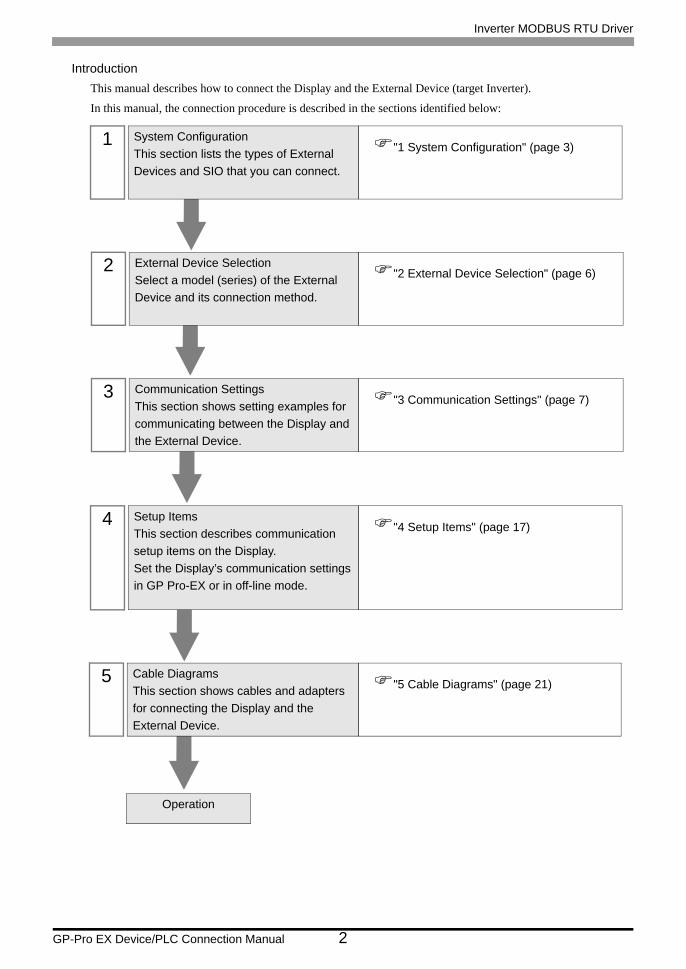
IntroductionThis manual describes how to connect the Display and the External Device (target Inverter).
In this manual, the connection procedure is described in the sections identified below:
1 System ConfigurationThis section lists the types of External Devices and SIO that you can connect.
"1 System Configuration" (page 3)
2 External Device SelectionSelect a model (series) of the External Device and its connection method.
"2 External Device Selection" (page 6)
3 Communication SettingsThis section shows setting examples for communicating between the Display and the External Device.
"3 Communication Settings" (page 7)
4 Setup ItemsThis section describes communication setup items on the Display.Set the Display’s communication settings in GP Pro-EX or in off-line mode.
"4 Setup Items" (page 17)
5 Cable DiagramsThis section shows cables and adapters for connecting the Display and the External Device.
"5 Cable Diagrams" (page 21)
Operation

Inverter MODBUS RTU Driver
GP-Pro EX Device/PLC Connection Manual 3
1 System Configuration
The following table lists system configurations for connecting Hitachi IES Co., Ltd. External Devices and the
Display.
Connection Configuration• 1:1 Connection
• 1:n Connection (when using either COM1 or COM2)
Series Inverter*1
*1 is not added as an option. differs depending on the option.
Link I/F SIO Type Setting Example Cable Diagram
X200 X200- F Serial port connector on the inverter
RS-422/485(2 wire)
"Setting Example 1" (page 7)
" Cable Diagram 1" (page 21)
SJ700 SJ700- F F RS485 port on the inverter
RS-422/485(2 wire)
"Setting Example 2" (page 9)
" Cable Diagram 2" (page 28)
SJ700-2 SJ700- F F2 RS485 port on the inverter
RS-422/485(2 wire)
"Setting Example 3" (page 11)
" Cable Diagram 2" (page 28)
SJ200 SJ200- F Serial port connector on the inverter
RS-422/485(2 wire)
"Setting Example 4" (page 13)
" Cable Diagram 1" (page 21)
L200 L200- F Serial port connector on the inverter
RS-422/485(2 wire)
"Setting Example 5" (page 15)
" Cable Diagram 1" (page 21)
DisplayExternal Device
Display
External Device External Device External Device
Maximum number of External Devices: 16

Inverter MODBUS RTU Driver
GP-Pro EX Device/PLC Connection Manual 4
IPC COM PortWhen connecting IPC with an External Device, the COM port used depends on the series and SIO type. Please
refer to the IPC manual for details.
Usable port
DIP switch setting: RS-232C
SeriesUsable port
RS-232C RS-422/485 (4 wire) RS-422/485 (2 wire)
PS-2000B COM1*1 , COM2, COM3*1, COM4
*1 The RI/5V can be switched. Use the IPC’s switch to change if necessary.
- -
PS-3450A, PS-3451A COM1, COM2*1*2 COM2*1*2 COM2*1*2
PS-3650A, PS-3651A COM1*1 - -
PS-3700A (Pentium®4-M)PS-3710A
COM1*1, COM2*1, COM3*2 , COM4
*2 Set up the SIO type with the DIP switch. Please set up as follows according to SIO type to be used.
COM3*2 COM3*2
PS-3711A COM1*1, COM2*2 COM2*2 COM2*2
PL-3000B, PL-3600T,PL-3600K, PL-3700T,PL-3700K, PL-3900T
COM1*1*2, COM2*1, COM3, COM4 COM1*1*2 COM1*1*2
DIP switch Setting Description
1 OFF*1
*1 When using PS-3450A and PS-3451A, turn ON the set value.
Reserved (always OFF)
2 OFFSIO type: RS-232C
3 OFF
4 OFF Output mode of SD (TXD) data: Always output
5 OFF Terminal resistance (220Ω) insertion to SD (TXD): None
6 OFF Terminal resistance (220Ω) insertion to RD (RXD): None
7 OFF Short-circuit of SDA (TXA) and RDA (RXA): Not available
8 OFF Short-circuit of SDB (TXB) and RDB (RXB): Not available
9 OFFRS (RTS) Auto control mode: Disabled
10 OFF

Inverter MODBUS RTU Driver
GP-Pro EX Device/PLC Connection Manual 5
DIP switch setting: RS-422/485 (4 wire)
DIP switch setting: RS-422/485 (2 wire)
DIP switch Setting Description
1 OFF Reserved (always OFF)
2 ONSIO type: RS-422/485
3 ON
4 OFF Output mode of SD (TXD) data: Always output
5 OFF Terminal resistance (220Ω) insertion to SD (TXD): None
6 OFF Terminal resistance (220Ω) insertion to RD (RXD): None
7 OFF Short-circuit of SDA (TXA) and RDA (RXA): Not available
8 OFF Short-circuit of SDB (TXB) and RDB (RXB): Not available
9 OFFRS (RTS) Auto control mode: Disabled
10 OFF
DIP switch Setting Description
1 OFF Reserved (always OFF)
2 ONSIO type: RS-422/485
3 ON
4 OFF Output mode of SD (TXD) data: Always output
5 OFF Terminal resistance (220Ω) insertion to SD (TXD): None
6 OFF Terminal resistance (220Ω) insertion to RD (RXD): None
7 ON Short-circuit of SDA (TXA) and RDA (RXA): Available
8 ON Short-circuit of SDB (TXB) and RDB (RXB): Available
9 ONRS (RTS) Auto control mode: Enabled
10 ON

Inverter MODBUS RTU Driver
GP-Pro EX Device/PLC Connection Manual 6
2 External Device Selection
Select the External Device to be connected to the Display.
Setup Items Setup Description
Maker Select the maker of the External Device to be connected. Select "Hitachi IES Co., Ltd.".
Series
Select a model (series) of the External Device to be connected and connection method. Select "Inverter MODBUS RTU".In System configuration, check to make sure the external device to which you are connecting is supported in "Inverter MODBUS RTU".
"1 System Configuration" (page 3)
Use System Area Not available in this driver.
Port Select the Display port to be connected to the External Device.
Inverter MODBUS RTU Driver
GP-Pro EX Device/PLC Connection Manual 7
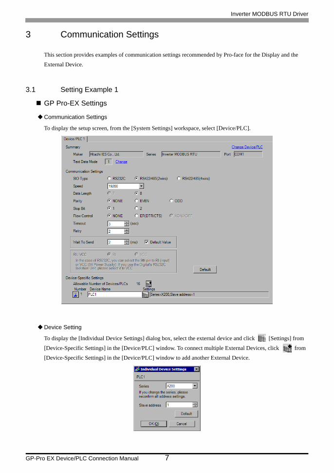
3 Communication Settings
This section provides examples of communication settings recommended by Pro-face for the Display and the
External Device.
3.1 Setting Example 1
GP Pro-EX Settings
Communication Settings
To display the setup screen, from the [System Settings] workspace, select [Device/PLC].
Device Setting
To display the [Individual Device Settings] dialog box, select the external device and click [Settings] from
[Device-Specific Settings] in the [Device/PLC] window. To connect multiple External Devices, click from
[Device-Specific Settings] in the [Device/PLC] window to add another External Device.

Inverter MODBUS RTU Driver
GP-Pro EX Device/PLC Connection Manual 8
External Device SettingsFor External Device communication settings, use the FUNC key, Up key, Down key, and STR key located in the
keypad of the External Device.
Refer to your External Device manual for details.
1 Set OPE/485 switch to "485" position.
2 Turn ON the External Device.
3 Press FUNC key.
4 Press and hold Down key to display [C---].
5 Press FUNC key.
6 Press Up key to display the setting function code.
7 Press FUNC key.
8 Press Up key or Down key to select the setting value.
9 Press STR key.
10 Reboot the External Device.
Setting Value
Function Code Setting Value Setup Description
C070 03 Selection of OPE/ModBus
C071 06 Communication speed selection
C072 1. Node allocation
C074 00 Communication parity selection
C075 1 Communication stop bit selection
C076 02 Communication error select
C077 0.00 Communication error time-out
C078 0. Communication wait time
A001 03 Frequency source setting
A002 03 Run command source setting

Inverter MODBUS RTU Driver
GP-Pro EX Device/PLC Connection Manual 9
3.2 Setting Example 2
GP Pro-EX Settings
Communication Settings
To display the setup screen, from the [System Settings] workspace, select [Device/PLC].
Device Setting
To display the [Individual Device Settings] dialog box, select the external device and click [Settings] from
[Device-Specific Settings] in the [Device/PLC] window. To connect multiple External Devices, click from
[Device-Specific Settings] in the [Device/PLC] window to add another External Device.

Inverter MODBUS RTU Driver
GP-Pro EX Device/PLC Connection Manual 10
External Device SettingsFor External Device communication settings, use the FUNC key, Up key, Down key, and STR key located in the
keypad of the External Device.
Refer to your External Device manual for details.
1 Turn ON the External Device.
2 Press FUNC key for 3 seconds or longer.
3 Press FUNC key to display [d001].
4 Press and hold Down key to display [C---].
5 Press FUNC key.
6 Press Up key to display the setting function code.
7 Press FUNC key.
8 Press Up key or Down key to select the setting value.
9 Press STR key.
10 Reboot the External Device.
Setting Value
Function Code Setting Value Setup Description
C071 06 Communication speed selection
C072 1. Node allocation
C073 8 Communication data length selection
C074 00 Communication parity selection
C075 1 Communication stop bit selection
C076 02 Selection of operation after communication error
C077 0.00 Communication trip limit time setting
C078 0. Communication wait time
C079 01 Communication mode selection
A001 03 Frequency source setting
A002 03 Run command source setting

Inverter MODBUS RTU Driver
GP-Pro EX Device/PLC Connection Manual 11
3.3 Setting Example 3
GP Pro-EX Settings
Communication Settings
To display the setup screen, from the [System Settings] workspace, select [Device/PLC].
Device Setting
To display the [Individual Device Settings] dialog box, select the external device and click [Settings] from
[Device-Specific Settings] in the [Device/PLC] window. To connect multiple External Devices, click from
[Device-Specific Settings] in the [Device/PLC] window to add another External Device.

Inverter MODBUS RTU Driver
GP-Pro EX Device/PLC Connection Manual 12
External Device SettingsFor External Device communication settings, use the FUNC key, Up key, Down key, and STR key located in the
keypad of the External Device.
Refer to your External Device manual for details.
1 Turn ON the External Device.
2 Press FUNC key for 3 seconds or longer.
3 Press FUNC key to display [d001].
4 Press and hold Down key to display [C---].
5 Press FUNC key.
6 Press Up key to display the setting function code.
7 Press FUNC key.
8 Press Up key or Down key to select the setting value.
9 Press STR key.
10 Reboot the External Device.
Setting Value
Function Code Setting Value Setup Description
C071 06 Communication speed selection
C072 1. Node allocation
C073 8 Communication data length selection
C074 00 Communication parity selection
C075 1 Communication stop bit selection
C076 02 Selection of operation after communication error
C077 0.00 Communication trip limit time setting
C078 0. Communication wait time
C079 01 Communication mode selection
A001 03 Frequency source setting
A002 03 Run command source setting

Inverter MODBUS RTU Driver
GP-Pro EX Device/PLC Connection Manual 13
3.4 Setting Example 4
GP Pro-EX Settings
Communication Settings
To display the setup screen, from the [System Settings] workspace, select [Device/PLC].
Device Setting
To display the [Individual Device Settings] dialog box, select the external device and click [Settings] from
[Device-Specific Settings] in the [Device/PLC] window. To connect multiple External Devices, click from
[Device-Specific Settings] in the [Device/PLC] window to add another External Device.

Inverter MODBUS RTU Driver
GP-Pro EX Device/PLC Connection Manual 14
External Device SettingsFor External Device communication settings, use the FUNC key, Up key, Down key, and STR key located in the
keypad of the External Device.
Refer to your External Device manual for details.
1 Set OPE/485 switch to "485" position.
2 Turn ON the External Device.
3 Press FUNC key.
4 Press and hold Down key to display [C---].
5 Press FUNC key.
6 Press Up key to display the setting function code.
7 Press FUNC key.
8 Press Up key or Down key to select the setting value.
9 Press STR key.
10 Reboot the External Device.
Setting Value
Function Code Setting Value Setup Description
C071 06 Communication speed selection
C072 1. Node allocation
C074 00 Communication parity selection
C075 1 Communication stop bit selection
C078 0. Communication wait time
A001 03 Frequency source setting
A002 03 Run command source setting

Inverter MODBUS RTU Driver
GP-Pro EX Device/PLC Connection Manual 15
3.5 Setting Example 5
GP Pro-EX Settings
Communication Settings
To display the setup screen, from the [System Settings] workspace, select [Device/PLC].
Device Setting
To display the [Individual Device Settings] dialog box, select the external device and click [Settings] from
[Device-Specific Settings] in the [Device/PLC] window. To connect multiple External Devices, click from
[Device-Specific Settings] in the [Device/PLC] window to add another External Device.

Inverter MODBUS RTU Driver
GP-Pro EX Device/PLC Connection Manual 16
External Device SettingsFor External Device communication settings, use the FUNC key, Up key, Down key, and STR key located in the
keypad of the External Device.
Refer to your External Device manual for details.
1 Set OPE/485 switch to "485" position.
2 Turn ON the External Device.
3 Press FUNC key.
4 Press and hold Down key to display [C---].
5 Press FUNC key.
6 Press Up key to display the setting function code.
7 Press FUNC key.
8 Press Up key or Down key to select the setting value.
9 Press STR key.
10 Reboot the External Device.
Setting Value
Function Code Setting Value Setup Description
C071 06 Communication speed selection
C072 1. Node allocation
C074 00 Communication parity selection
C075 1 Communication stop bit selection
C078 0. Communication wait time
A001 03 Frequency source setting
A002 03 Run command source setting

Inverter MODBUS RTU Driver
GP-Pro EX Device/PLC Connection Manual 17
4 Setup Items
Set up the Display’s communication settings in GP Pro-EX or in the Display’s off-line mode.
The setting of each parameter must match that of the External Device.
"3 Communication Settings" (page 7)
4.1 Setup Items in GP Pro-EX
Communication SettingsTo display the setup screen, from the [System Settings] workspace, select [Device/PLC].
Setup Items Setup Description
SIO Type
Select the SIO type to communicate with the External Device.
In the communication settings, set [SIO Type] correctly according to the serial interface specifications of the Display.If you select an SIO type that the serial interface does not support, proper operation cannot be guaranteed.Refer to your Display manual for details on the serial interface specifications.
Speed Select communication speed between the External Device and the Display.
Data Length Display data length.
Parity Select how to check parity.
Stop Bit Select stop bit length.
Continued on the next page.

Inverter MODBUS RTU Driver
GP-Pro EX Device/PLC Connection Manual 18
Device SettingTo display the [Individual Device Settings] dialog box, select the external device and click [Settings] from
[Device-Specific Settings] in the [Device/PLC] window. To connect multiple External Devices, click from
[Device-Specific Settings] in the [Device/PLC] window to add another External Device.
Flow Control Select the communication control method to prevent overflow of transmission and reception data.
Timeout Use an integer from 1 to 127 to enter the time (s) for which the Display waits for the response from the External Device.
Retry In case of no response from the External Device, use an integer from 0 to 255 to enter how many times the Display retransmits the command.
Wait To Send
Use an integer from 0 to 255 to enter standby time (ms) for the Display from receiving packets to transmitting next commands.When the default value check box is selected, the Wait To Send value automatically changes in the formula below by changing each value for Speed/Data Length/Parity/Stop Bit.
Value for the parity setting is shown below. No Parity = 0 Parity Even = 1 Parity Odd = 1
• After changing the Wait To Send value for the project, of which [Default Value] is checked, in the off-line mode, the Wait To Send value will be recalculated when the project is received and communication settings are displayed.
Setup Items Setup Description
Series Select the series of the External Device.
Slave address Use an integer from 1 to 32 to enter the address of the External Device.
Setup Items Setup Description
Wait To Send (ms) =Speed (bps)
3500 x (1 + Data Length + Stop Bit + Parity)

Inverter MODBUS RTU Driver
GP-Pro EX Device/PLC Connection Manual 19
4.2 Setup Items in Off-line Mode
Communication SettingsTo display the setting screen, touch [Device/PLC Settings] from [Peripheral Equipment Settings] in off-line mode.
Touch the External Device you want to set from the displayed list.
• Refer to the Maintenance/Troubleshooting manual for information on how to enter off-line mode or about the operation.Cf. Maintenance/Troubleshooting Manual "2.2 Off-line Mode"
Setup Items Setup Description
SIO Type
Select the SIO type to communicate with the External Device.
In the communication settings, set [SIO Type] correctly according to the serial interface specifications of the Display.If you select an SIO type that the serial interface does not support, proper operation cannot be guaranteed.Refer to your Display manual for details on the serial interface specifications.
Speed Select the communication speed between the External Device and the Display.
Data Length Display data length.
Parity Select how to check parity.
Stop Bit Select stop bit length.
Flow Control Select the communication control method to prevent overflow of transmission and reception data.
Continued on the next page.

Inverter MODBUS RTU Driver
GP-Pro EX Device/PLC Connection Manual 20
Device SettingTo display the setting screen, touch [Device/PLC Settings] from [Peripheral Equipment Settings]. Touch the
External Device you want to set from the displayed list, and touch [Device].
Timeout (s) Use an integer from 1 to 127 to enter the time (s) for which the Display waits for the response from the External Device.
Retry In case of no response from the External Device, use an integer from "0 to 255" to enter how many times the Display retransmits the command.
Wait To Send Use an integer from 0 to 255 to enter standby time (ms) for the Display from receiving packets to transmitting next commands.
Setup Items Setup Description
Device/PLC Name Select the External Device to set. Device name is a title of the External Device set with GP-Pro EX. (Initial value [PLC1])
Series Display the series of the External Device.
Slave address Use an integer from 1 to 32 to enter the address of the External Device.
Setup Items Setup Description
Inverter MODBUS RTU Driver
GP-Pro EX Device/PLC Connection Manual 21
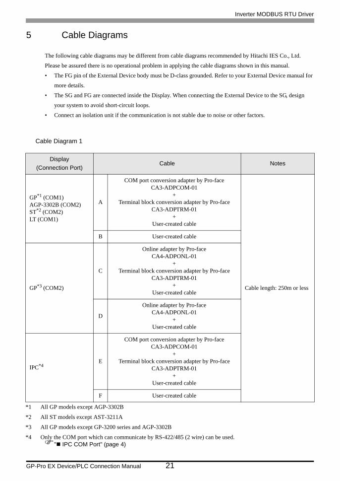
5 Cable Diagrams
The following cable diagrams may be different from cable diagrams recommended by Hitachi IES Co., Ltd.
Please be assured there is no operational problem in applying the cable diagrams shown in this manual.
• The FG pin of the External Device body must be D-class grounded. Refer to your External Device manual for
more details.
• The SG and FG are connected inside the Display. When connecting the External Device to the SG, design
your system to avoid short-circuit loops.
• Connect an isolation unit if the communication is not stable due to noise or other factors.
Cable Diagram 1
Display(Connection Port)
Cable Notes
GP*1 (COM1)AGP-3302B (COM2)ST*2 (COM2)LT (COM1)
*1 All GP models except AGP-3302B
*2 All ST models except AST-3211A
A
COM port conversion adapter by Pro-faceCA3-ADPCOM-01
+Terminal block conversion adapter by Pro-face
CA3-ADPTRM-01+
User-created cable
Cable length: 250m or less
B User-created cable
GP*3 (COM2)
*3 All GP models except GP-3200 series and AGP-3302B
C
Online adapter by Pro-faceCA4-ADPONL-01
+Terminal block conversion adapter by Pro-face
CA3-ADPTRM-01+
User-created cable
D
Online adapter by Pro-faceCA4-ADPONL-01
+User-created cable
IPC*4
*4 Only the COM port which can communicate by RS-422/485 (2 wire) can be used." IPC COM Port" (page 4)
E
COM port conversion adapter by Pro-faceCA3-ADPCOM-01
+Terminal block conversion adapter by Pro-face
CA3-ADPTRM-01+
User-created cable
F User-created cable

Inverter MODBUS RTU Driver
GP-Pro EX Device/PLC Connection Manual 22
A) When using the COM port conversion adapter (CA3-ADPCOM-01), the terminal block conversion adapter
(CA3-ADPTRM-01) by Pro-face, and a user-created cable
• 1:1 Connection
• 1:n Connection
TERM
RDA
RDB
SDA
SDB
SG
FG
Signal name
Display sideTerminal Block
SP
SN
External Device sideRJ45 connector
Signal name
5
6
Pin
CA3-ADPTRM-01CA3-ADPCOM-01
Display
User-created cable
Shield
Terminationresistance200Ω
Terminationresistance
200Ω
SP
SN
External Device sideRJ45 connector
Signal name
5
6
Pin
TERM
RDA
RDB
SDA
SDB
SG
FG
Signal name
Display sideTerminal Block
SP
SN
External Device sideRJ45 connector
Signal name
5
6
Pin
CA3-ADPTRM-01CA3-ADPCOM-01
Display
User-created cable
Shield
Shield Terminationresistance200Ω
Terminationresistance
200Ω
Inverter MODBUS RTU Driver
GP-Pro EX Device/PLC Connection Manual 23
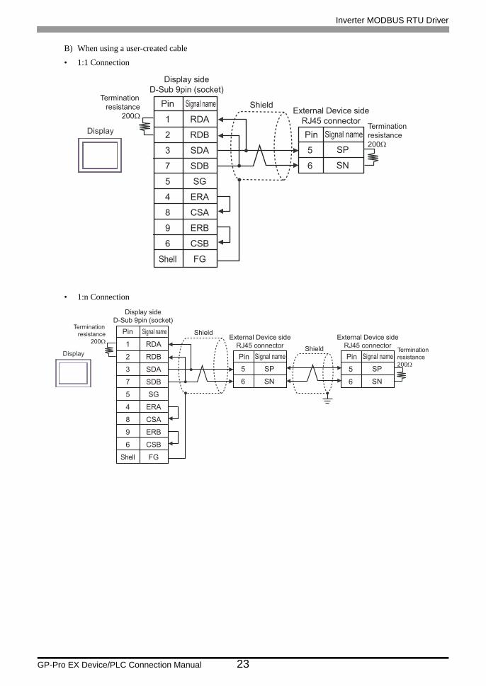
B) When using a user-created cable
• 1:1 Connection
• 1:n Connection
Shield
Display
Signal name
1
2
3
7
5
4
8
9
6
Shell
Pin
Display sideD-Sub 9pin (socket)
RDA
RDB
SDA
SDB
SG
ERA
CSA
ERB
CSB
FG
Terminationresistance
200Ω
SP
SN
External Device sideRJ45 connector
Signal name
5
6
PinTerminationresistance200Ω
Shield
Display
Signal name
1
2
3
7
5
4
8
9
6
Shell
Pin
Display sideD-Sub 9pin (socket)
RDA
RDB
SDA
SDB
SG
ERA
CSA
ERB
CSB
FG
Terminationresistance
200Ω
SP
SN
5
6
External Device sideRJ45 connector
Signal namePinSP
SN
External Device sideRJ45 connector
Signal name
5
6
PinShield Termination
resistance200Ω

Inverter MODBUS RTU Driver
GP-Pro EX Device/PLC Connection Manual 24
C) When using the online adapter (CA4-ADPONL-01), the terminal block conversion adapter
(CA3-ADPTRM-01) by Pro-face, and a user-created cable
• 1:1 Connection
• 1:n Connection
ShieldTerminationresistance
200Ω
Display sideTerminal Block
CA3-ADPTRM-01CA4-ADPONL-01
Display
TERM
RDA
RDB
SDA
SDB
SG
FG
Signal name
User-created cable
SP
SN
External Device sideRJ45 connector
Signal name
5
6
PinTerminationresistance200Ω
Shield
Display sideTerminal Block
CA3-ADPTRM-01CA4-ADPONL-01
DisplayTERM
RDA
RDB
SDA
SDB
SG
FG
Signal name
User-created cable
SP
SN
5
6
External Device sideRJ45 connector
Signal namePinSP
SN
External Device sideRJ45 connector
Signal name
5
6
PinShield Termination
resistance200Ω
Terminationresistance
200Ω
Inverter MODBUS RTU Driver
GP-Pro EX Device/PLC Connection Manual 25
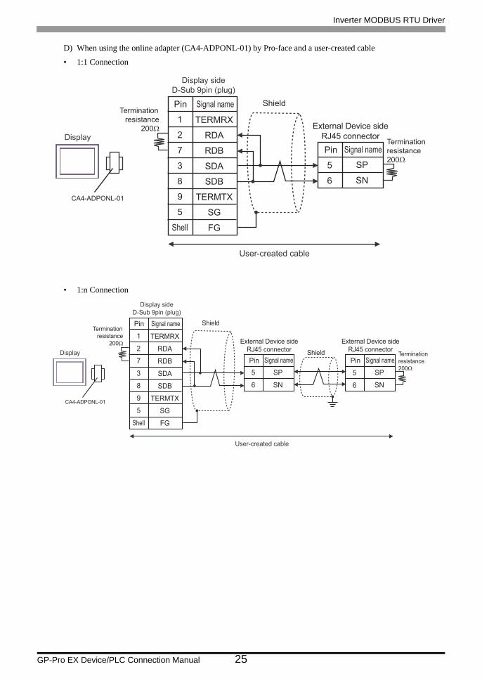
D) When using the online adapter (CA4-ADPONL-01) by Pro-face and a user-created cable
• 1:1 Connection
• 1:n Connection
ShieldTermination
resistance200Ω
CA4-ADPONL-01
Display
Display sideD-Sub 9pin (plug)
TERMRX
RDA
RDB
SDA
SDB
TERMTX
SG
FG
Signal name
1
2
7
3
8
9
5
Shell
Pin
User-created cable
SP
SN
External Device sideRJ45 connector
Signal name
5
6
PinTerminationresistance200Ω
ShieldTermination
resistance200Ω
CA4-ADPONL-01
Display
Display sideD-Sub 9pin (plug)
TERMRX
RDA
RDB
SDA
SDB
TERMTX
SG
FG
Signal name
1
2
7
3
8
9
5
Shell
Pin
User-created cable
SP
SN
5
6
External Device sideRJ45 connector
Signal namePinSP
SN
External Device sideRJ45 connector
Signal name
5
6
PinShield Termination
resistance200Ω

Inverter MODBUS RTU Driver
GP-Pro EX Device/PLC Connection Manual 26
E) When using the COM port conversion adapter (CA3-ADPCOM-01), the terminal block conversion adapter
(CA3-ADPTRM-01) by Pro-face, and a user-created cable
• 1:1 Connection
• 1:n Connection
TERM
RDA
RDB
SDA
SDB
SG
FG
Signal name
External Device sideTerminal Block
CA3-ADPTRM-01CA3-ADPCOM-01
Display
User-created cable
Shield
SP
SN
External Device sideRJ45 connector
Signal name
5
6
PinTerminationresistance200Ω
Terminationresistance
200Ω
TERM
RDA
RDB
SDA
SDB
SG
FG
Signal name
External Device sideTerminal Block
CA3-ADPTRM-01CA3-ADPCOM-01
Display
User-created cable
Shield
SP
SN
5
6
External Device sideRJ45 connector
Signal namePinSP
SN
External Device sideRJ45 connector
Signal name
5
6
PinShield Termination
resistance200Ω
Terminationresistance
200Ω

Inverter MODBUS RTU Driver
GP-Pro EX Device/PLC Connection Manual 27
F) When using a user-created cable
• 1:1 Connection
• 1:n Connection
Shield
Display
Signal name
1
2
3
7
5
4
8
9
6
Shell
Pin
Display sideD-Sub 9pin (socket)
DATA+
DATA-
NC
NC
GND(SG)
ERA
CSA
ERB
CSB
FG
Terminationresistance
200ΩSP
SN
External Device sideRJ45 connector
Signal name
5
6
PinTerminationresistance200Ω
Shield
Display
Signal name
1
2
3
7
5
4
8
9
6
Shell
Pin
Display sideD-Sub 9pin (socket)
DATA+
DATA-
NC
NC
GND(SG)
ERA
CSA
ERB
CSB
FG
Terminationresistance
200ΩSP
SN
5
6
External Device sideRJ45 connector
Signal namePinSP
SN
External Device sideRJ45 connector
Signal name
5
6
PinShield Termination
resistance200Ω

Inverter MODBUS RTU Driver
GP-Pro EX Device/PLC Connection Manual 28
Cable Diagram 2
Display(Connection Port)
Cable Notes
GP*1 (COM1)AGP-3302B (COM2)ST*2 (COM2)LT (COM1)
*1 All GP models except AGP-3302B
*2 All ST models except AST-3211A
A
COM port conversion adapter by Pro-faceCA3-ADPCOM-01
+Terminal block conversion adapter by Pro-face
CA3-ADPTRM-01+
User-created cable
Cable length: 250m or less
B User-created cable
GP*3 (COM2)
*3 All GP models except GP-3200 series and AGP-3302B
C
Online adapter by Pro-faceCA4-ADPONL-01
+Terminal block conversion adapter by Pro-face
CA3-ADPTRM-01+
User-created cable
D
Online adapter by Pro-faceCA4-ADPONL-01
+User-created cable
IPC*4
*4 Only the COM port which can communicate by RS-422/485 (2 wire) can be used." IPC COM Port" (page 4)
E
COM port conversion adapter by Pro-faceCA3-ADPCOM-01
+Terminal block conversion adapter by Pro-face
CA3-ADPTRM-01+
User-created cable
F User-created cable

Inverter MODBUS RTU Driver
GP-Pro EX Device/PLC Connection Manual 29
A) When using the COM port conversion adapter (CA3-ADPCOM-01), the terminal block conversion adapter
(CA3-ADPTRM-01) by Pro-face, and a user-created cable
• 1:1 Connection
• 1:n Connection
• Enable termination resistance by short-circuiting the terminatory External Device’s RP terminal and the terminatory External Device’s SN terminal.
TERM
RDA
RDB
SDA
SDB
SG
FG
Signal name
Display sideTerminal Block
SP
SN
RP
SN
External Device sideTM2 Terminal Block
Signal name
CA3-ADPTRM-01CA3-ADPCOM-01
Display
User-created cable
ShieldTermination
resistance200Ω
SP
SN
RP
SN
External Device sideTM2 Terminal Block
Signal name
TERM
RDA
RDB
SDA
SDB
SG
FG
Signal name
Display sideTerminal Block
SP
SN
RP
SN
External Device sideTM2 Terminal Block
Signal name
CA3-ADPTRM-01CA3-ADPCOM-01
Display
User-created cable
Shield
Shield
Terminationresistance
200Ω
Inverter MODBUS RTU Driver
GP-Pro EX Device/PLC Connection Manual 30
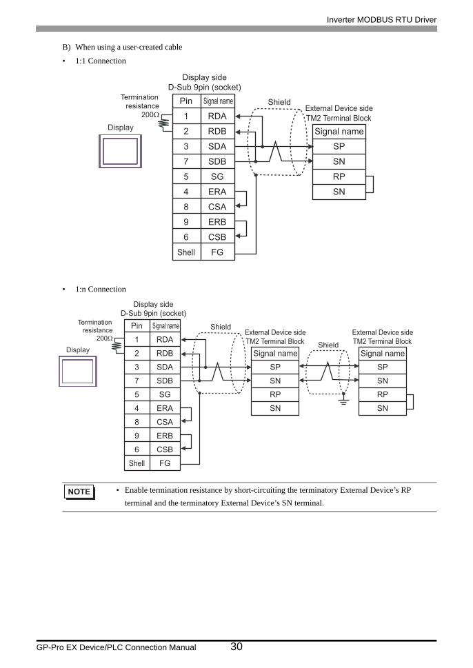
B) When using a user-created cable
• 1:1 Connection
• 1:n Connection
• Enable termination resistance by short-circuiting the terminatory External Device’s RP terminal and the terminatory External Device’s SN terminal.
Shield
Display
Signal name
1
2
3
7
5
4
8
9
6
Shell
Pin
Display sideD-Sub 9pin (socket)
RDA
RDB
SDA
SDB
SG
ERA
CSA
ERB
CSB
FG
Terminationresistance
200Ω
SP
SN
RP
SN
External Device sideTM2 Terminal Block
Signal name
Shield
Display
Signal name
1
2
3
7
5
4
8
9
6
Shell
Pin
Display sideD-Sub 9pin (socket)
RDA
RDB
SDA
SDB
SG
ERA
CSA
ERB
CSB
FG
Terminationresistance
200Ω
SP
SN
RP
SN
External Device sideTM2 Terminal Block
Signal name
SP
SN
RP
SN
External Device sideTM2 Terminal Block
Signal nameShield

Inverter MODBUS RTU Driver
GP-Pro EX Device/PLC Connection Manual 31
C) When using the online adapter (CA4-ADPONL-01), the terminal block conversion adapter
(CA3-ADPTRM-01) by Pro-face and a user-created cable
• 1:1 Connection
• 1:n Connection
• Enable termination resistance by short-circuiting the terminatory External Device’s RP terminal and the terminatory External Device’s SN terminal.
ShieldTerminationresistance
200Ω
Display sideTerminal Block
CA3-ADPTRM-01CA4-ADPONL-01
Display
TERM
RDA
RDB
SDA
SDB
SG
FG
Signal name
User-created cable
SP
SN
RP
SN
External Device sideTM2 Terminal Block
Signal name
Shield
Display sideTerminal Block
CA3-ADPTRM-01CA4-ADPONL-01
Display
TERM
RDA
RDB
SDA
SDB
SG
FG
Signal name
User-created cable
SP
SN
RP
SN
External Device sideTM2 Terminal Block
Signal name
SP
SN
RP
SN
External Device sideTM2 Terminal Block
Signal nameShield
Terminationresistance
200Ω

Inverter MODBUS RTU Driver
GP-Pro EX Device/PLC Connection Manual 32
D) When using the online adapter (CA4-ADPONL-01) by Pro-face and a user-created cable
• 1:1 Connection
• 1:n Connection
• Enable termination resistance by short-circuiting the terminatory External Device’s RP terminal and the terminatory External Device’s SN terminal.
Shield
CA4-ADPONL-01
Display
Display sideD-Sub 9pin (plug)
TERMRX
RDA
RDB
SDA
SDB
TERMTX
SG
FG
Signal name
1
2
7
3
8
9
5
Shell
Pin
User-created cable
SP
SN
RP
SN
External Device sideTM2 Terminal Block
Signal name
Terminationresistance
200Ω
Shield
CA4-ADPONL-01
Display
Display sideD-Sub 9pin (plug)
TERMRX
RDA
RDB
SDA
SDB
TERMTX
SG
FG
Signal name
1
2
7
3
8
9
5
Shell
Pin
User-created cable
SP
SN
RP
SN
External Device sideTM2 Terminal Block
Signal name
SP
SN
RP
SN
External Device sideTM2 Terminal Block
Signal nameShield
Terminationresistance
200Ω

Inverter MODBUS RTU Driver
GP-Pro EX Device/PLC Connection Manual 33
E) When using the COM port conversion adapter (CA3-ADPCOM-01), the terminal block conversion adapter
(CA3-ADPTRM-01) by Pro-face, and a user-created cable
• 1:1 Connection
• 1:n Connection
• Enable termination resistance by short-circuiting the terminatory External Device’s RP terminal and the terminatory External Device’s SN terminal.
TERM
RDA
RDB
SDA
SDB
SG
FG
Signal name
Display sideTerminal Block
CA3-ADPTRM-01CA3-ADPCOM-01
Display
User-created cable
Shield
SP
SN
RP
SN
External Device sideTM2 Terminal Block
Signal nameTermination
resistance200Ω
TERM
RDA
RDB
SDA
SDB
SG
FG
Signal name
Display sideTerminal Block
CA3-ADPTRM-01CA3-ADPCOM-01
Display
User-created cable
Shield
SP
SN
RP
SN
External Device sideTM2 Terminal Block
Signal name
SP
SN
RP
SN
External Device sideTM2 Terminal Block
Signal nameShieldTermination
resistance200Ω

Inverter MODBUS RTU Driver
GP-Pro EX Device/PLC Connection Manual 34
F) When using a user-created cable
• 1:1 Connection
• 1:n Connection
• Enable termination resistance by short-circuiting the terminatory External Device’s RP terminal and the terminatory External Device’s SN terminal.
Shield
Display
Signal name
1
2
3
7
5
4
8
9
6
Shell
Pin
Display sideD-Sub 9pin (socket)
DATA+
DATA-
NC
NC
GND(SG)
ERA
CSA
ERB
CSB
FG
Terminationresistance
200Ω SP
SN
RP
SN
External Device sideTM2 Terminal Block
Signal name
Shield
Display
Signal name
1
2
3
7
5
4
8
9
6
Shell
Pin
Display sideD-Sub 9pin (socket)
DATA+
DATA-
NC
NC
GND(SG)
ERA
CSA
ERB
CSB
FG
Terminationresistance
200Ω SP
SN
RP
SN
External Device sideTM2 Terminal Block
Signal name
SP
SN
RP
SN
External Device sideTM2 Terminal Block
Signal nameShield

Inverter MODBUS RTU Driver
GP-Pro EX Device/PLC Connection Manual 35
6 Supported Devices
The following table shows the range of supported device addresses. Please note that the actually supported range
of the devices varies depending on the External Device to be used. Please check the actual range in the manual of
your External Device.
6.1 X200 series
This address can be specified as system data area.
6.2 SJ700 series
This address can be specified as system data area.
Device Bit Address Word Address 32bits Notes
Coil 00001 - 0001F 00001 *1
*1 Specify only the word address whose last digit is "1" .
Holding register - 40001 - 41544
• Holding register number 0900h is an address for the command (enter command) to write in nonvolatile memory. By writing "1" in 0900h, writing to nonvolatile memory is enabled.
• You can only set the Read Area Size for the system area available to use in the External Device. Please refer to the GP Pro-EX Reference Manual for Read Area Size.Cf. GP Pro-EX Reference Manual "Appendix 1.4 LS Area (Direct Access Method)"
• Refer to the precautions on manual notation for icons in the table.
"Manual Symbols and Terminology"
Device Bit Address Word Address 32bits Notes
Coil 00001 - 0004E 00001 - 00031 *1
*1 Specify only the word address whose last digit is "1".
Holding register - 40001 - 43507
• Holding register number 0900h is an address for the command (enter command) to write in nonvolatile memory. By writing "1" in 0900h, writing to nonvolatile memory is enabled.
• You can only set the Read Area Size for the system area available to use in the External Device. Please refer to the GP Pro-EX Reference Manual for Read Area Size.Cf. GP Pro-EX Reference Manual "Appendix 1.4 LS Area (Direct Access Method)"
• Refer to the precautions on manual notation for icons in the table.
"Manual Symbols and Terminology"

Inverter MODBUS RTU Driver
GP-Pro EX Device/PLC Connection Manual 36
6.3 SJ700-2 series This address can be specified as system data area.
6.4 SJ200 series This address can be specified as system data area.
Device Bit Address Word Address 32bits Notes
Coil 00001 - 00052 00001 - 00041 *1
*1 Specify only the word address whose last digit is "1".
Holding register - 40001 - 43507
• Holding register number 0900h is an address for the command (enter command) to write in nonvolatile memory. By writing "1" in 0900h, writing to nonvolatile memory is enabled.
• You can only set the Read Area Size for the system area available to use in the External Device. Please refer to the GP Pro-EX Reference Manual for Read Area Size.Cf. GP Pro-EX Reference Manual "Appendix 1.4 LS Area (Direct Access Method)"
• Refer to the precautions on manual notation for icons in the table.
"Manual Symbols and Terminology"
Device Bit Address Word Address 32bits Notes
Coil 00000 - 0001F 00000 - 00010
Holding register - 40000 - 40900
• Holding register number 0900h is an address for the command (enter command) to write in nonvolatile memory. By writing "1" in 0900h, writing to nonvolatile memory is enabled.
• You can only set the Read Area Size for the system area available to use in the External Device. Please refer to the GP Pro-EX Reference Manual for Read Area Size.Cf. GP Pro-EX Reference Manual "Appendix 1.4 LS Area (Direct Access Method)"
• Refer to the precautions on manual notation for icons in the table.
"Manual Symbols and Terminology"
Inverter MODBUS RTU Driver
GP-Pro EX Device/PLC Connection Manual 37
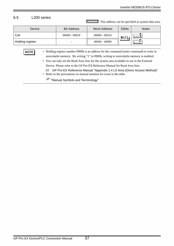
6.5 L200 series This address can be specified as system data area.
Device Bit Address Word Address 32bits Notes
Coil 00000 - 0001F 00000 - 00010
Holding register - 40000 - 40900
• Holding register number 0900h is an address for the command (enter command) to write in nonvolatile memory. By writing "1" in 0900h, writing to nonvolatile memory is enabled.
• You can only set the Read Area Size for the system area available to use in the External Device. Please refer to the GP Pro-EX Reference Manual for Read Area Size.Cf. GP Pro-EX Reference Manual "Appendix 1.4 LS Area (Direct Access Method)"
• Refer to the precautions on manual notation for icons in the table.
"Manual Symbols and Terminology"

Inverter MODBUS RTU Driver
GP-Pro EX Device/PLC Connection Manual 38
7 Device Code and Address Code
Use device codes and address codes when you set "Device Type & Address" for the address type of the data
display or other devices.
7.1 X200 series
7.2 SJ700 series
7.3 SJ700-2 series
7.4 SJ200 series
7.5 L200 series
Device Device NameDevice Code
(HEX)Address Code
Coil 0 0080 Value of (word address -1) divided by 0x10
Holding register 4 0000 Value of (word address - 1)
Device Device NameDevice Code
(HEX)Address Code
Coil 0 0080 Value of (word address -1) divided by 0x10
Holding register 4 0000 Value of (word address - 1)
Device Device NameDevice Code
(HEX)Address Code
Coil 0 0080 Value of (word address -1) divided by 0x10
Holding register 4 0000 Value of (word address - 1)
Device Device NameDevice Code
(HEX)Address Code
Coil 0 0080 Value of word address divided by 0x10
Holding register 4 0000 Word Address
Device Device NameDevice Code
(HEX)Address Code
Coil 0 0080 Value of word address divided by 0x10
Holding register 4 0000 Word Address

Inverter MODBUS RTU Driver
GP-Pro EX Device/PLC Connection Manual 39
8 Error Messages
Error messages are displayed on the Display screen as follows: "No. : Device Name: Error Message (Error
Occurrence Area)". Each description is shown below.
Examples of Error Messages
"RHAA035:PLC1: Error has been responded for device write command (Error Code: 2 [02H])"
Error Codes Unique to External Device
Item Description
No. Error number
Device Name Name of the External Device where an error has occurred. Device/PLC name is the title of the External Device set with GP Pro-EX. (Initial value [PLC1])
Error Message Displays messages related to an error that has occurred.
Error Occurrence Area
Displays the IP address or device address of the External Device where an error has occurred, or error codes received from the External Device.
• IP address is displayed as "IP address (Decimal): MAC address (Hex)".• Device address is displayed as "Address: Device address".• Received error codes are displayed as "Decimal [Hex]".
• Refer to your External Device manual for details on received error codes.• Refer to "When an error is displayed (Error Code List)" in "Maintenance/Troubleshooting
Manual" for details on the error messages common to the driver.
Error Code Description
02h The specified address does not exist.
21h Invalid data is written in the inverter’s holding register.
22h
These specified functions are not available to the inverter:• Attempted to change the content of a register that cannot be changed while the inverter
is in service.• Attempted to use an ENTER command during running (UV).• Attempted to write in a register during tripping (UV).• Attempted to write in a register with software lock enabled.
23h*1
*1 The error code is only supported by X200 series.
Attempted to write in a register with software lock enabled.