Embed Size (px)
Citation preview

3/7/2015
1
LINEAR CIRCUIT ANALYSIS (EED) – U.E.T. TAXILA 07
ENGR. M. MANSOOR ASHRAF
INTRODUCTION
Applying Kirchhoff’s laws to purely resistive circuitsresults in algebraic equations.
While applying laws to RC and RL circuits producesdifferential equations, which are more difficult to solvethan algebraic equations.
The differential equations resulting from analyzing RCand RL circuits are of the first order.
Hence, the circuits are collectively known as first-ordercircuits.
3/7/2015
2
INTRODUCTION
A First-Order Circuit is characterized by a first-orderdifferential equation.
There are two ways to excite the RC and RL circuits.
The first way is by initial conditions of the storageelements in the circuits, so called source-free circuits.
The second way of exciting first order circuits is byindependent sources and these sources will be DCsources.
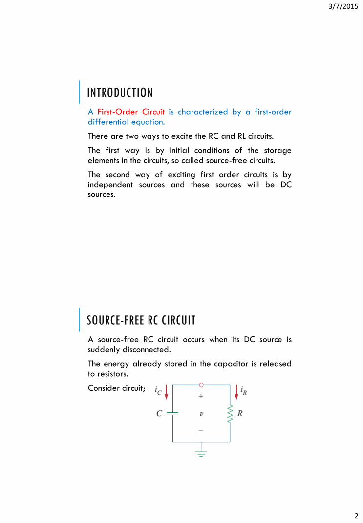
SOURCE-FREE RC CIRCUIT
A source-free RC circuit occurs when its DC source issuddenly disconnected.
The energy already stored in the capacitor is releasedto resistors.
Consider circuit;

3/7/2015
3
SOURCE-FREE RC CIRCUIT
Since capacitor is initially charged and voltage v(t)across capacitor at time t=0 is;
The corresponding value of energy stored;
Applying KCL at top node of circuit;
SOURCE-FREE RC CIRCUIT
By definition;
Putting values;
The first-order differential equation;
3/7/2015
4
SOURCE-FREE RC CIRCUIT
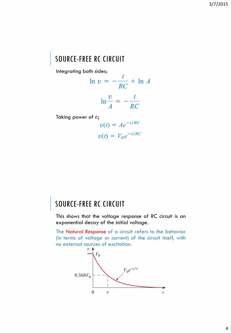
Integrating both sides;
Taking power of e;
SOURCE-FREE RC CIRCUIT
This shows that the voltage response of RC circuit is anexponential decay of the initial voltage.
The Natural Response of a circuit refers to the behavior(in terms of voltage or current) of the circuit itself, withno external sources of excitation.
3/7/2015
5
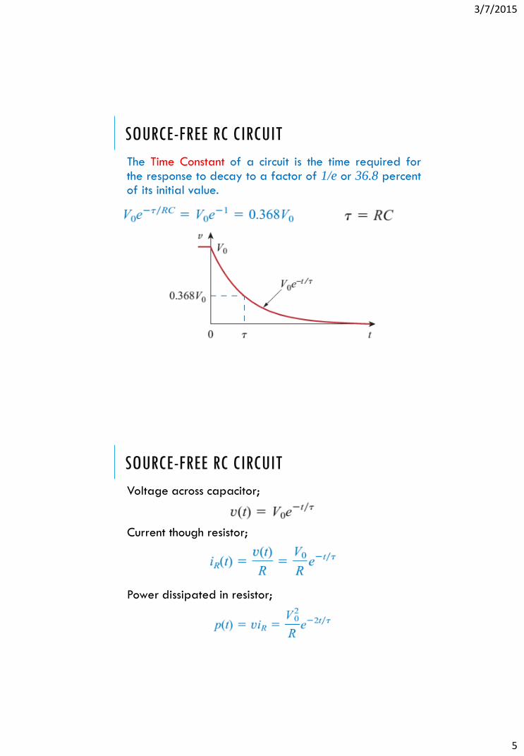
SOURCE-FREE RC CIRCUIT
The Time Constant of a circuit is the time required forthe response to decay to a factor of 1/e or 36.8 percentof its initial value.
SOURCE-FREE RC CIRCUIT
Voltage across capacitor;
Current though resistor;
Power dissipated in resistor;

3/7/2015
6
SOURCE-FREE RC CIRCUIT
Energy absorbed by the resistor;
SOURCE-FREE RC CIRCUIT
3/7/2015
7
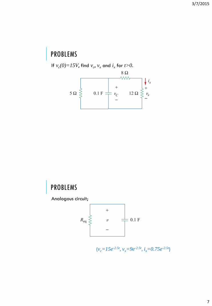
PROBLEMS
If vc(0)=15V, find vc, vx and ix for t>0.
PROBLEMS
Analogous circuit;
(vc=15e-2.5t, vx=9e-2.5t, ix=0.75e-2.5t)

3/7/2015
8
PROBLEMS
The switch in the circuit has been closed for a long time,and it is opened at t=0. Find v(t) for t>0 and initialstored energy?
PROBLEMS
For t<0 the switched is closed;
(Vo=15V)

3/7/2015
9
PROBLEMS
For t>0 the switched is opened;
(v(t)=15e-5t, wc(0)=2.25J)
SOURCE-FREE RL CIRCUIT
A source-free RL circuit occurs when its DC source issuddenly disconnected.
The energy already stored in the inductor is released toresistors.
Consider circuit;

3/7/2015
10
SOURCE-FREE RL CIRCUIT
Since inductor is initially charged and current i(t)through inductor at time t=0 is;
The corresponding value of energy stored;
Applying KVL around the loop;
SOURCE-FREE RL CIRCUIT
By definition;
Putting values;
Rearranging and integrating;

3/7/2015
11
SOURCE-FREE RL CIRCUIT
Integrating both sides;
Taking power of e;
SOURCE-FREE RL CIRCUIT
This shows that the current response of RL circuit is anexponential decay of the initial current.
The Natural Response of a circuit refers to the behavior(in terms of voltage or current) of the circuit itself, withno external sources of excitation.
Time constant; Current through inductor;

3/7/2015
12
SOURCE-FREE RL CIRCUIT
The Time Constant of a circuit is the time required forthe response to decay to a factor of 1/e or 36.8 percentof its initial value.
SOURCE-FREE RL CIRCUIT
Current through inductor;
Voltage across resistor;
Power dissipated in resistor;

3/7/2015
13
SOURCE-FREE RL CIRCUIT
Energy absorbed by the resistor;
PROBLEMS
If i(0)=10A, find i(t) and ix(t) for t>0.

3/7/2015
14
PROBLEMS
Finding equivalent resistance;
(Req=1/3 ohm, i(t)=10e-(2/3)t, ix(t)=1.667e-(2/3)t)
PROBLEMS
The switch in the circuit has been closed for a long time,and it is opened at t=0. Find i(t) for t>0.

3/7/2015
15
PROBLEMS
For t<0 the switched is closed;
(Io=6A)
PROBLEMS
For t>0 the switched is opened;
(i(t)=6e-4t)

3/7/2015
16
PROBLEMS
The switch in the circuit has been opened for a longtime, and it is closed at t=0. Find io, vo and i for t>0.
PROBLEMS
For t<0 the switched is opened;
(io=2A, vo=6V)

3/7/2015
17
PROBLEMS
For t>0 the switched is closed;
(i(t)=2e-t, io(t)=-(2/3)e-t)
PROBLEMS
For all time;

3/7/2015
18
PROBLEMS
Plotting graphs;
SINGULARITY FUNCTIONS
Singularity functions are very useful in circuit analysis.
A basic understanding of singularity functions will helpin understanding the response of first-order circuits to asudden application of independent sources (DC voltageor current).
Singularity Functions are functions that either arediscontinuous or have discontinuous derivatives.
The three most widely used singularity functions in circuitanalysis are, unit step, unit impulse and unit rampfunctions.
3/7/2015
19
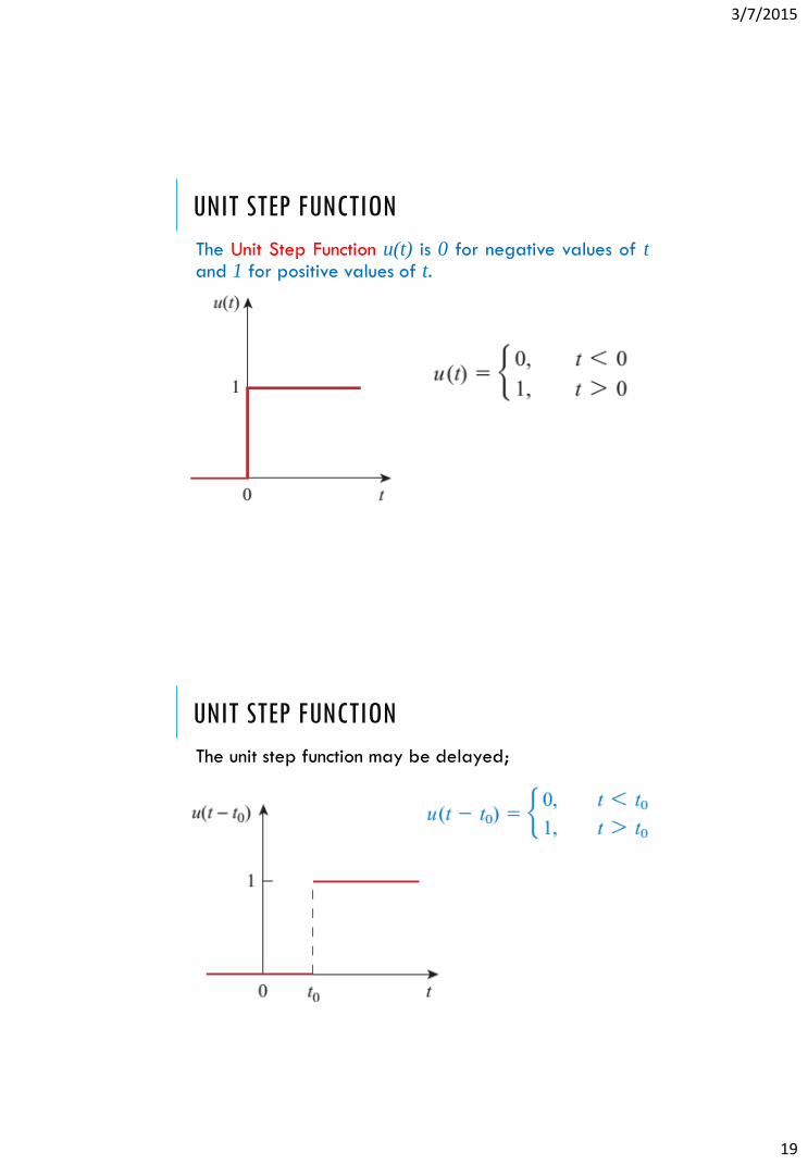
UNIT STEP FUNCTION
The Unit Step Function u(t) is 0 for negative values of tand 1 for positive values of t.
UNIT STEP FUNCTION
The unit step function may be delayed;

3/7/2015
20
UNIT STEP FUNCTION
The unit step function may be advanced;
UNIT STEP FUNCTION
Voltage source may be expressed in terms of unit stepfunction;

3/7/2015
21
UNIT STEP FUNCTION
Current source may be expressed in terms of unit stepfunction;
UNIT IMPULSE FUNCTION
The Unit Impulse Function δ(t) is zero everywhere exceptat t=0, where it is undefined.
The derivative of u(t) is δ(t).

3/7/2015
22
UNIT IMPULSE FUNCTION
Advancing and delaying of impulse function;
UNIT RAMP FUNCTION
The Unit Ramp Function r(t) is zero for negative valuesof t and has a unit slope for positive values of t.
The integral of u(t) is r(t).

3/7/2015
23
UNIT RAMP FUNCTION
Delayed unit ramp function;
UNIT RAMP FUNCTION
Advanced unit ramp function;

3/7/2015
24
SINGULARITY FUNCTIONS
Relationships between different singularity functions;
PROBLEMS
Express the voltage in terms of unit step function andalso calculate its derivative.

3/7/2015
25
PROBLEMS
First and second parts;
PROBLEMS
Derivative of unit step function;

3/7/2015
26
PROBLEMS
Express saw tooth function in terms of singularityfunctions?
PROBLEMS
First;

3/7/2015
27
PROBLEMS
Second;
REFERENCES
Fundamentals of Electric Circuits (4th Edition)
Charles K. Alexander, Matthew N. O. Sadiku
Chapter 07 – First-Order Circuits (7.1 – 7.4)
Exercise Problems: 7.1 – 7.38
Do exercise problem yourself.

3/7/2015
28
STEP RESPONSE OF AN RC CIRCUIT
When the DC source of an RC circuit is suddenlyapplied, the voltage or current source can be modeledas a step function, and the response is known as stepresponse.
The Step Response of a circuit is its behavior when theexcitation is the step function, which may be a voltageor current source.
The step response is the response of the circuit due to asudden application of a DC voltage or current source.
STEP RESPONSE OF AN RC CIRCUIT
Consider circuit;
Voltage across capacitor in intervals;
3/7/2015
29
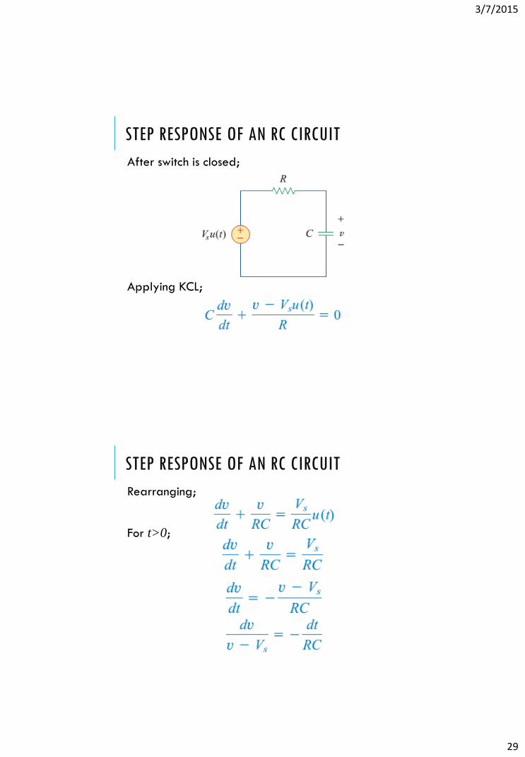
STEP RESPONSE OF AN RC CIRCUIT
After switch is closed;
Applying KCL;
STEP RESPONSE OF AN RC CIRCUIT
Rearranging;
For t>0;

3/7/2015
30
STEP RESPONSE OF AN RC CIRCUIT
Integrating;
Taking exponential;
STEP RESPONSE OF AN RC CIRCUIT
Rearranging;
Voltage across capacitor;
This is complete response of the RC circuit to a suddenapplication of DC source when capacitor is charged.

3/7/2015
31
STEP RESPONSE OF AN RC CIRCUIT
Response of the RC circuit when capacitor is charged;
STEP RESPONSE OF AN RC CIRCUIT
Response of the RC circuit when capacitor is uncharged;

3/7/2015
32
STEP RESPONSE OF AN RC CIRCUIT
Current through capacitor;
STEP RESPONSE OF AN RC CIRCUIT
Complete response of the RC circuit;
Where;

3/7/2015
33
STEP RESPONSE OF AN RC CIRCUIT
The Transient Response is the circuit’s temporaryresponse that will die out with time.
The Steady-State Response is the behavior of the circuita long time after an external excitation is applied.
It may also be expressed as;
Where;
PROBLEMS
The switch has been in position A for a long time. At t=0the switch moves to B. Find v(t) for t>0 and calculate itsvalue at t=1 s and t=4 s.
(v(t)=(30-15e-0.5t), 20.9V, 27.97V)

3/7/2015
34
STEP RESPONSE OF AN RL CIRCUIT
When the DC source of an RL circuit is suddenlyapplied, the voltage or current source can be modeledas a step function, and the response is known as stepresponse.
The Step Response of a circuit is its behavior when theexcitation is the step function, which may be a voltageor current source.
The step response is the response of the circuit due to asudden application of a DC voltage or current source.
STEP RESPONSE OF AN RL CIRCUIT
Consider circuit;
Let the response of RL circuit;

3/7/2015
35
STEP RESPONSE OF AN RL CIRCUIT
Transient response is always a decaying exponential;
The steady state response;
Substituting values;
Inductor’s initial current;
STEP RESPONSE OF AN RL CIRCUIT
At t=0;
Putting value of A, inductor current;
3/7/2015
36
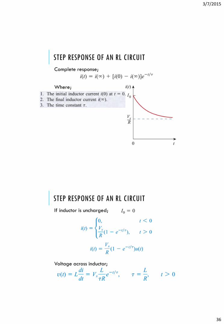
STEP RESPONSE OF AN RL CIRCUIT
Complete response;
Where;
STEP RESPONSE OF AN RL CIRCUIT
If inductor is uncharged;
Voltage across inductor;

3/7/2015
37
STEP RESPONSE OF AN RL CIRCUIT
Voltage across inductor;
PROBLEMS
Find i(t) in the circuit for t>0. Assume that switch hasbeen closed for long time.
(i(t)=(2+3e-15t))

3/7/2015
38
REFERENCES
Fundamentals of Electric Circuits (4th Edition)
Charles K. Alexander, Matthew N. O. Sadiku
Chapter 07 – First-Order Circuits (7.5 – 7.6)
Exercise Problems: 7.39 – 7.65
Do exercise problem yourself.