Embed Size (px)
Citation preview

20th AGATA WeekINFN - Legnaro 16th to 19th September 2019
Introduction to the Phase 2 electronicsV. González
University of Valencia - ETSE

18th AGATA WeekMilano 13th to 15th September 2017
Outline – AGATA Electronics evolution – Known Issues - Guidelines – General Description –Power Distribution – Mechanical Layout – Work Status - Conclusions
Outline
•AGATA Electronics Evolution•Known Issues•Guidelines •General Description•Power Distribution•Mechanical Layout•Work Status•Conclusions
1

Outline – AGATA Electronics Evolution – Known Issues - Guidelines – General Description –Power Distribution – Mechanical Layout – Work Status - Conclusions
AGATA Electronics Evolution
ATCA/Mezzanines
LINCO2
AGATA Electronics Phase 0/Early1 (23 - 25 ch available)
PCIe
AGATA Electronics Advanced Phase 1 (13 ch available)
New production batch of Adv. Phase 1 electronics10 channels + spares
We need to go for 4π AGATA
2
Outline – AGATA Electronics evolution – Known Issues - Guidelines – General Description –Power Distribution – Mechanical Layout – Work Status - Conclusions
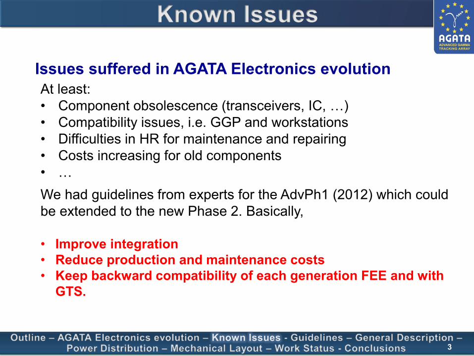
Known Issues
Issues suffered in AGATA Electronics evolutionAt least:• Component obsolescence (transceivers, IC, …)• Compatibility issues, i.e. GGP and workstations• Difficulties in HR for maintenance and repairing• Costs increasing for old components • …We had guidelines from experts for the AdvPh1 (2012) which could be extended to the new Phase 2. Basically,
• Improve integration• Reduce production and maintenance costs• Keep backward compatibility of each generation FEE and with
GTS.
3

Outline – AGATA Electronics evolution – Known Issues - Guidelines – General Description –Power Distribution – Mechanical Layout – Work Status - Conclusions
Important issues• Interface between front end electronics and servers should
not rely on any specific hardware interface.• Simplified and autonomous electronic modules to ease
maintenance and minimize impact of possible rework due to obsolete components in future.
• Highly integrated solution to ease the installation in experimental area.
• Readout based on high bandwidth network technology(up to 10 Gb/s per crystal).
• Stable and scalable architecture of the AGATA BEE&DAQ architecture (for which the necessary performances must be fulfilled from 45 up to 180 crystals)
Guidelines
Objective: to build a scalable and stable Back End Electronics and DAQ (Electronic Data Acquisition) system for AGATA beyond phase 1
4
Outline – AGATA Electronics evolution – Known Issues - Guidelines – General Description –Power Distribution – Mechanical Layout – Work Status - Conclusions
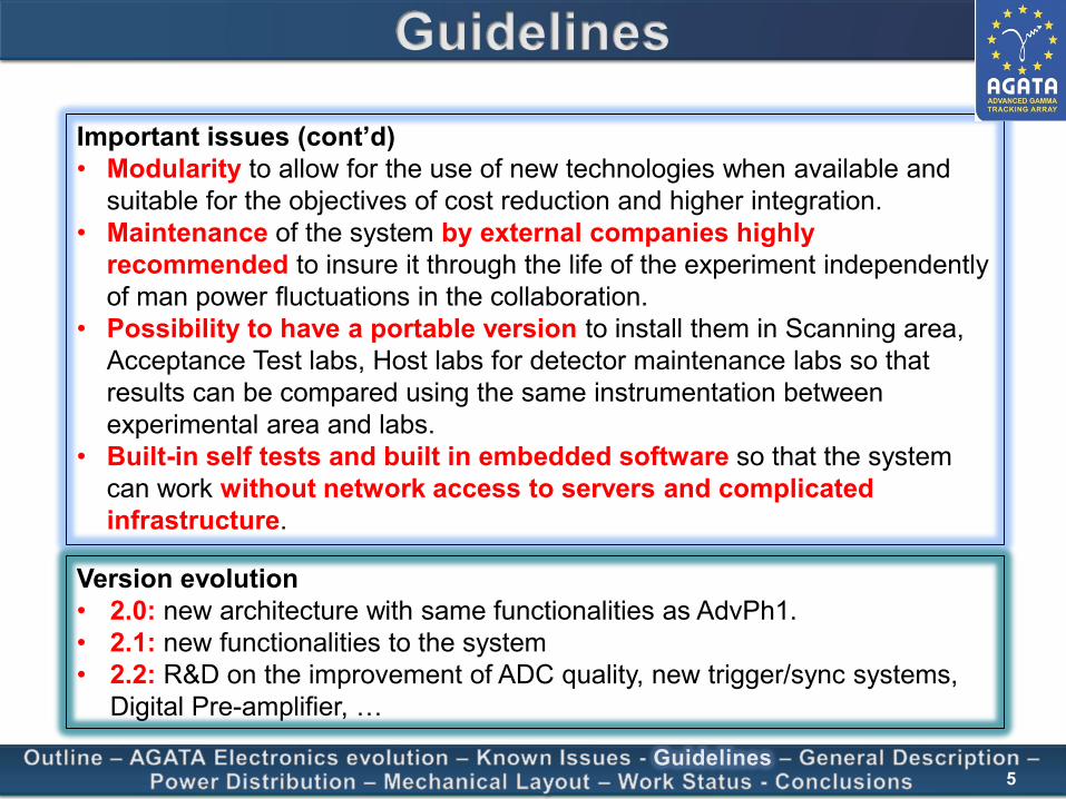
Guidelines
Important issues (cont’d)• Modularity to allow for the use of new technologies when available and
suitable for the objectives of cost reduction and higher integration.• Maintenance of the system by external companies highly
recommended to insure it through the life of the experiment independently of man power fluctuations in the collaboration.
• Possibility to have a portable version to install them in Scanning area, Acceptance Test labs, Host labs for detector maintenance labs so that results can be compared using the same instrumentation between experimental area and labs.
• Built-in self tests and built in embedded software so that the system can work without network access to servers and complicated infrastructure.
Version evolution• 2.0: new architecture with same functionalities as AdvPh1.• 2.1: new functionalities to the system• 2.2: R&D on the improvement of ADC quality, new trigger/sync systems,
Digital Pre-amplifier, …
5

Outline – AGATA Electronics evolution – Known Issues - Guidelines – General Description –Power Distribution – Mechanical Layout – Work Status - Conclusions
PACE system
General DescriptionGeneral Layout
HWIFIC & ETSE, Valencia
CSNSM, OrsayINFN & U. Milano
SWCSNSM, Orsay
FWIPHC, Strasbourg
MonitoringSTFC, Daresbury
• PACE: Processing and Control over Ethernet• IDM: Input Data Mezzanine: aggregates data to
reduce the number of connections from DigiOpt12 to CAP
• CAP: Control and Processing: integrates the Control Card and GGP functionalities
• STARE: Serial Transfer Acquisition Readout over Ethernet: Possible 10 Gb/s Ethernet connection mezzanine. Otherwise integrated in CAP.
• GTSO: GTS leaf mezzanine
6
1:1 Crystal – RO Electronics Ratio

Outline – AGATA Electronics evolution – Known Issues - Guidelines – General Description –Power Distribution – Mechanical Layout – Work Status - Conclusions
General DescriptionPACE Block Diagram Functional Layout
IDM CAP
Main features• SOM module Zynq Ultrascale FPGA.
Compared to GGP Virtex• ~ 3 times more logic cells• ~ 1.5 times more BRAM• ~ 3.8 times more DRAM• ~ 6 times more DSP
• 10 year support from manufacturer (Trenz Electronics)
STARE
Main features• Cooper connection to DigiOPT12• Reduce the number of GTH transceivers• 4:1 channel aggregation TLK10022
Main features• Multiple 10 Gbps Ethernet data output
• Data readout• Monitoring, inspection, …
7
Outline – AGATA Electronics evolution – Known Issues - Guidelines – General Description –Power Distribution – Mechanical Layout – Work Status - Conclusions
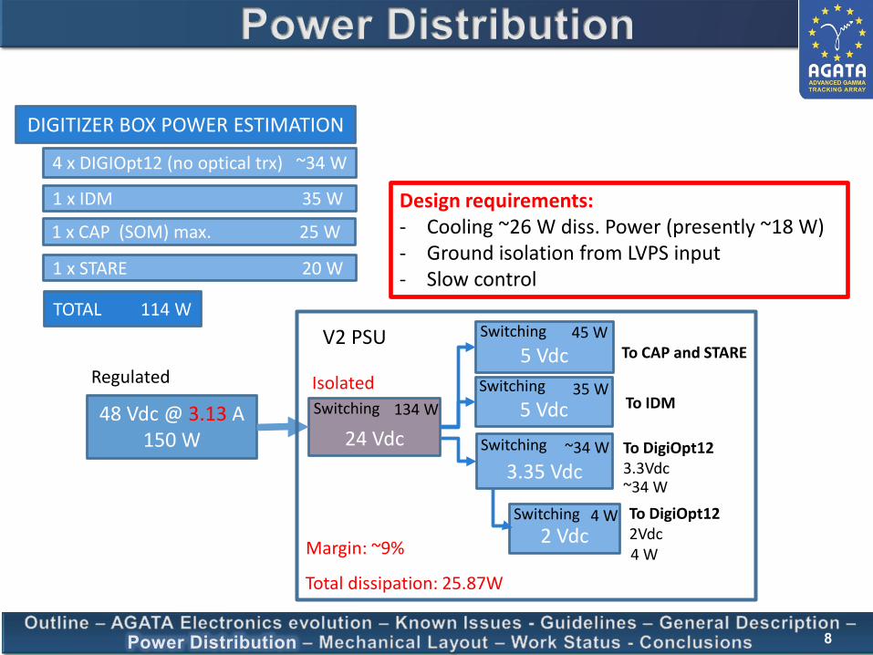
Power Distribution
1 x IDM 35 W
4 x DIGIOpt12 (no optical trx) ~34 W
1 x STARE 20 W
1 x CAP (SOM) max. 25 W
TOTAL 114 W
DIGITIZER BOX POWER ESTIMATION
48 Vdc @ 3.13 A150 W 24 Vdc
5 Vdc
5 Vdc
3.35 Vdc
V2 PSU
Design requirements:- Cooling ~26 W diss. Power (presently ~18 W)- Ground isolation from LVPS input- Slow control
45 W
35 W
~34 W
~34 W
Switching
Total dissipation: 25.87W
2 Vdc4 W
Switching
Switching
Switching
Switching
To CAP and STARE
To IDM
To DigiOpt12 3.3Vdc
To DigiOpt12 2Vdc4 W
134 W
Margin: ~9%
Isolated
8
Regulated

Outline – AGATA Electronics evolution – Known Issues - Guidelines – General Description –Power Distribution – Mechanical Layout – Work Status - Conclusions
Mechanical Layout
Ethernet OutputGTS Connection MDR Inputs
Cooling
Design requirement:- Keep present 3U 19’’ crate
9
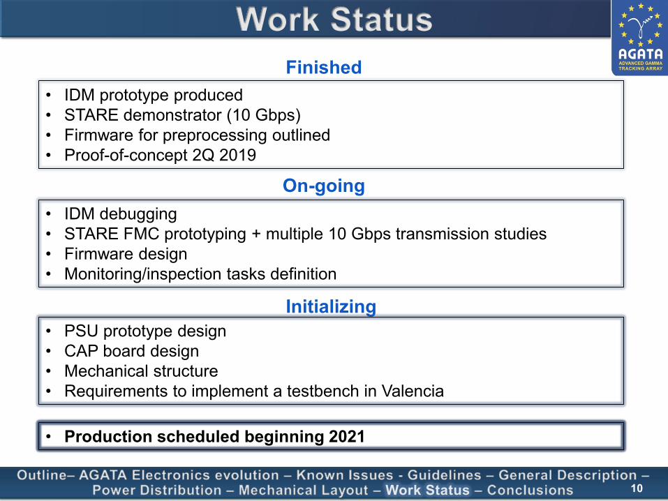
Outline– AGATA Electronics evolution – Known Issues - Guidelines – General Description –Power Distribution – Mechanical Layout – Work Status – Conclusions
Work Status
• IDM prototype produced• STARE demonstrator (10 Gbps)• Firmware for preprocessing outlined • Proof-of-concept 2Q 2019
• Production scheduled beginning 2021
• IDM debugging• STARE FMC prototyping + multiple 10 Gbps transmission studies• Firmware design• Monitoring/inspection tasks definition
• PSU prototype design• CAP board design• Mechanical structure• Requirements to implement a testbench in Valencia
Finished
On-going
Initializing
10

Outline– AGATA Electronics evolution – Known Issues - Guidelines – General Description –Power Distribution – Mechanical Layout - Work Status – Conclusions
Conclusions
• System conceived following the guidelines of experts• Higher integration and compact design• Use of Ethernet readout• More easy maintenance• Modularity• Backward compatibility
• Proof-of-concept test performed
On-going
Works is progressing but we expect a very busy (an successful) 2020!
11

Thank you for your attention