Embed Size (px)
Citation preview

Introduction to Solid Modeling
Martiale G. ZEBAZE KANA

Outline
Background Introduction to Solid Modeling
Solid Model Representation Schemes
Solid Primitives
Operations on Primitives
Hands-on session on Autodesk Fusion 360
Solid Modeling Software
I
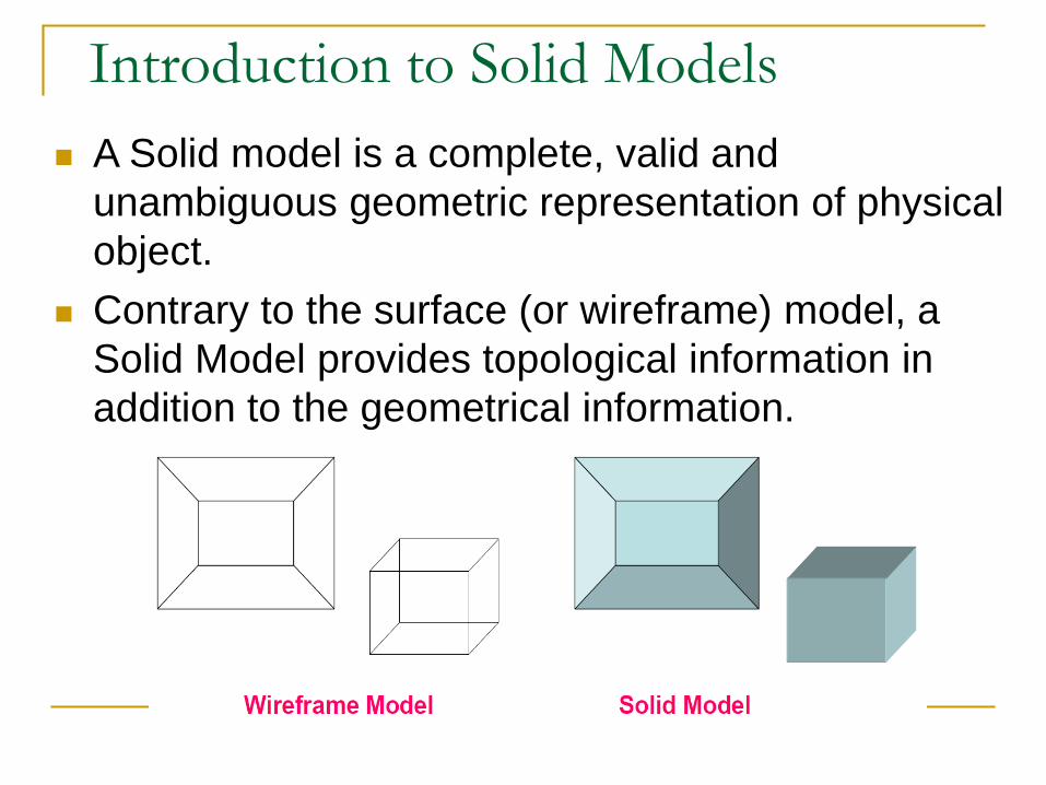
Introduction to Solid Models
A Solid model is a complete, valid and
unambiguous geometric representation of physical
object.
Contrary to the surface (or wireframe) model, a
Solid Model provides topological information in
addition to the geometrical information.

Why Solid Modeling?
Solid modeling provides a solution to the weakness
of wireframe and surface modelling, namely
Ambiguity and incompleteness in the geometric
description in Wireframe /surface modeling
Lack of topological information in wireframe / surface
modeling
Complexity of the modeling process
Precise models of parts and assemblies are created
using solid modeling software
3D solid modeling package allows users to develop full
solid models in a simulated environment for both design
and analysis

Solid Models Analysis automation and integration is possible
only with solid models: has properties such as
weight, moment of inertia, mass.
Solid model consist of geometric and topological
data
Solid Modeling is used by students, designers,
engineers, and other professionals to produce
simple and complex parts, assemblies, and
drawings.
This approach saves time, effort, and money that
would otherwise be spent prototyping the design.

Some Solid Model Representation Schemes
Boundary Representation (B-Rep)
Constructive Solid Geometry (CSG)
Sweeping
Primitive Instancing
3 most popular schemes : B-rep, CSG, Sweeping
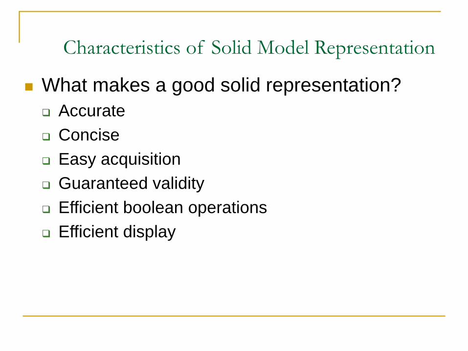
Characteristics of Solid Model Representation
What makes a good solid representation?
Accurate
Concise
Easy acquisition
Guaranteed validity
Efficient boolean operations
Efficient display

Constructive Solid Geometry (CSG)
Objects are represented as a combination of
simpler solid objects (primitives).
The primitives are such as cube, cylinder,
cone, torus, sphere, etc.
Copies or “instances” of these primitive shapes
are created and positioned.
A complete solid model is constructed by
combining these “instances” using set specific,
logic operations (Boolean Operators)

Solid Primitives
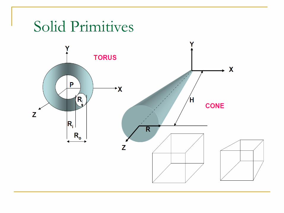
Solid Primitives

CSG – Boolean Operations
Each primitive solid is assumed to be a set of
points, a boolean operation is performed on
point sets and the result is a solid model.
Boolean operation union, intersection and
difference
The relative location and orientation of the two
primitives have to be defined before the
boolean operation can be performed.
Boolean operation can be applied to two solids
other than the primitives.

Boolean Operations: Union
The Boolean Operation “Union” represents the sum of all
points in each of two defined sets - (logical “OR”). Also
referred to as Add, Combine, Join, Merge

Boolean Operations- Difference
The Boolean Operator
“Difference” represents
the points in a source set
minus the points
common to a second set
- (logical “NOT”)
Set must share common
volume,
Also referred to as
subtraction, remove, cut

Boolean Operations: Intersection
The Intersection
Operator refers tothose
points common to each
of two defined sets
(logical “AND”)
Set must share
common volume
Also referred to as
common, conjoin


Components - PARTSA Solid model has some basic components:
➢The first, and most basic element of a solid
model is a Part.
➢Parts consist of primitive geometry and
features such as extrudes, revolutions, lofts,
sweeps, etc.
➢Parts constitute the building blocks for all of
the models created
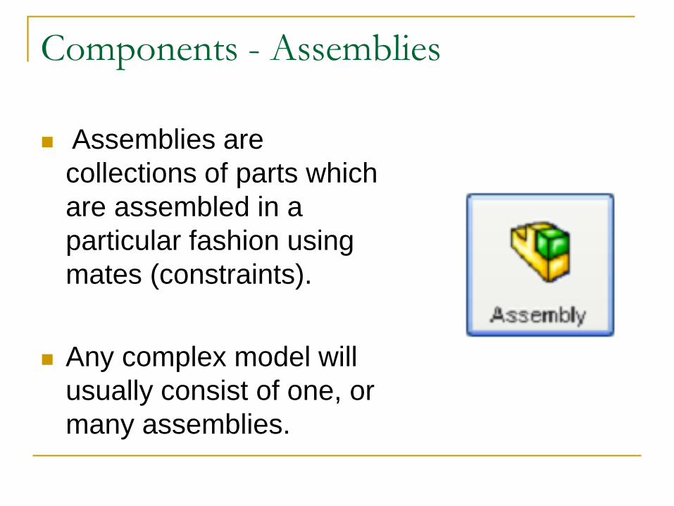
Components - Assemblies
Assemblies are
collections of parts which
are assembled in a
particular fashion using
mates (constraints).
Any complex model will
usually consist of one, or
many assemblies.

Some Solid Modeling Software SolidWorks
Fusion 360
BowlerStudio (Developed at WPI)
3D Studio Max
Maya
Blender
Etc