Embed Size (px)
Citation preview

1© 2015 The MathWorks, Inc.
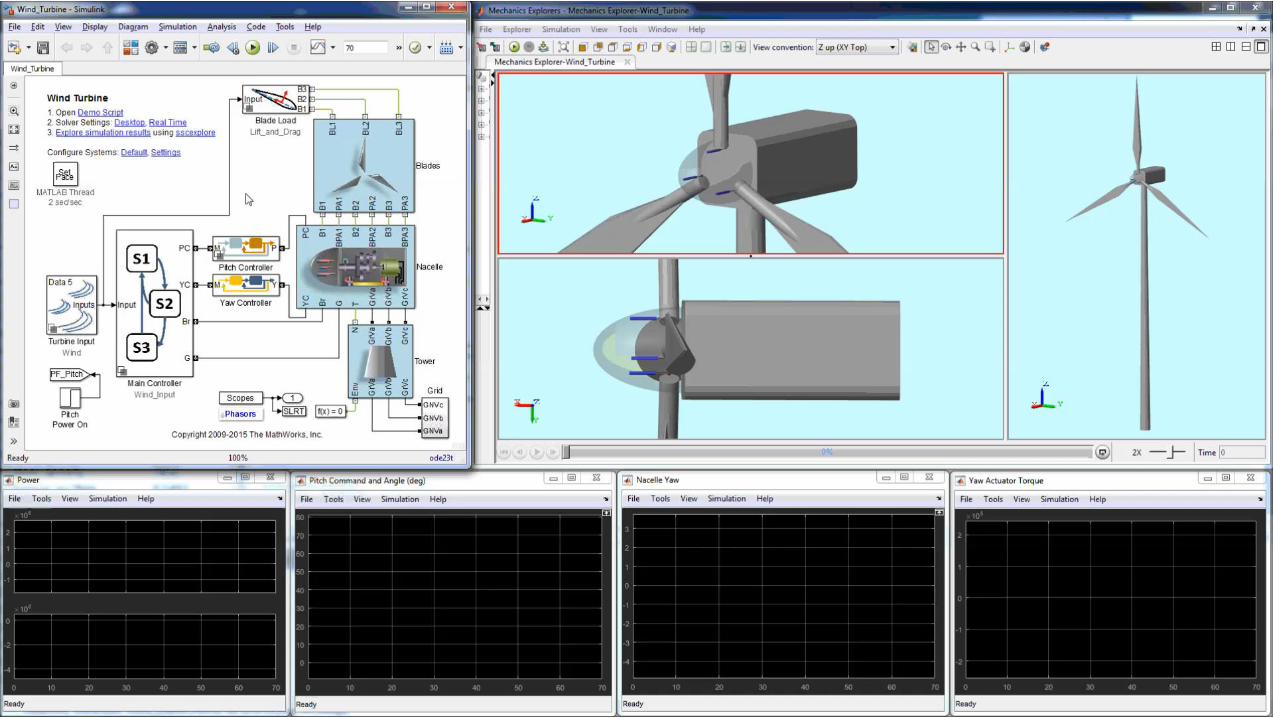
Introduction to Simulink & Stateflow
Jonathan Agg
2

4
Topics we will address this session
▪ Why model a system?
▪ Why use Simulink?
▪ Getting to grips with the basics of Simulink and Stateflow through a worked
example
6
Why model a system?
7
Modelling & Simulation
gives you insight

8
Image credit: McLaren
Image credit: Peter Gronemann | Wikipedia

11
MODEL
Integrate
Create
Import
SIMULATE
Test
Optimize
ConfigureAnalyze and
Document
DEPLOY
Integrate Into
Other Environments
Share Models
Test Controller
12
Why use
Simulink?
13
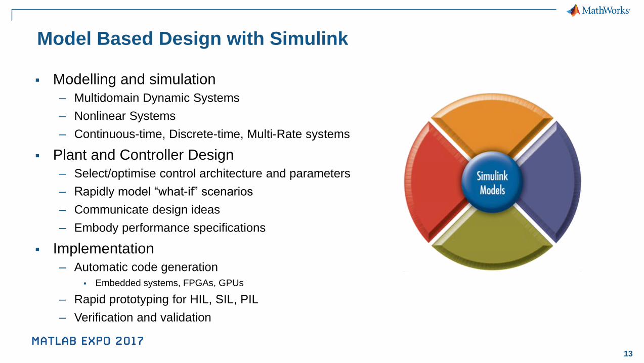
Model Based Design with Simulink
▪ Modelling and simulation
– Multidomain Dynamic Systems
– Nonlinear Systems
– Continuous-time, Discrete-time, Multi-Rate systems
▪ Plant and Controller Design
– Select/optimise control architecture and parameters
– Rapidly model “what-if” scenarios
– Communicate design ideas
– Embody performance specifications
▪ Implementation
– Automatic code generation
▪ Embedded systems, FPGAs, GPUs
– Rapid prototyping for HIL, SIL, PIL
– Verification and validation
14
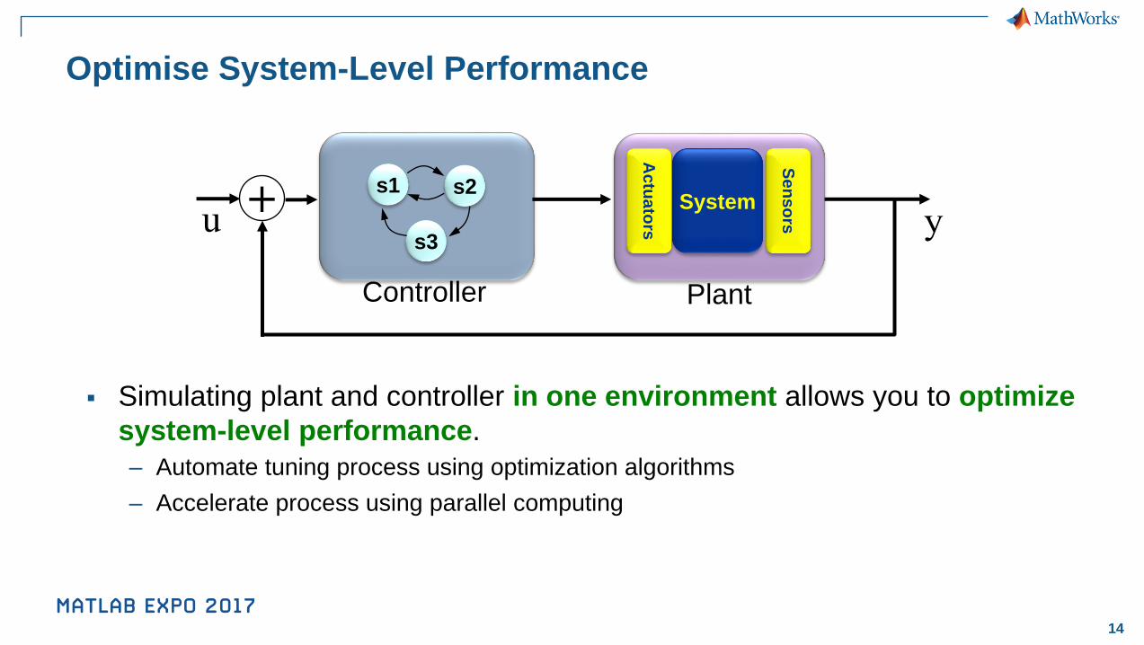
Optimise System-Level Performance
▪ Simulating plant and controller in one environment allows you to optimize
system-level performance.
– Automate tuning process using optimization algorithms
– Accelerate process using parallel computing
Plant
+u y
Controller
s1 s2
s3
System
Actu
ato
rs
Sen
so
rs
15
Plant
Specification
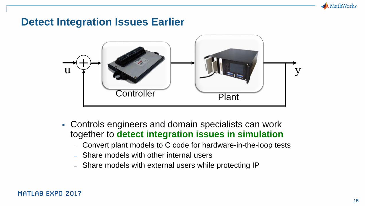
Detect Integration Issues Earlier
Plant
+u y
Controller
s1 s2
s3
▪ Controls engineers and domain specialists can work together to detect integration issues in simulation– Convert plant models to C code for hardware-in-the-loop tests
– Share models with other internal users
– Share models with external users while protecting IP
System
Actu
ato
rs
Sen
so
rs

16
Modelling Approaches
Data-Driven ModellingFirst Principles Modelling
Statistics and Machine
Learning Toolbox
Simscape SystemIdentification
ToolboxSimulink
Design Optimization
Simulink
MATLAB
Tools for Modelling Dynamic Systems
18
Using Simulink &
Stateflow

19
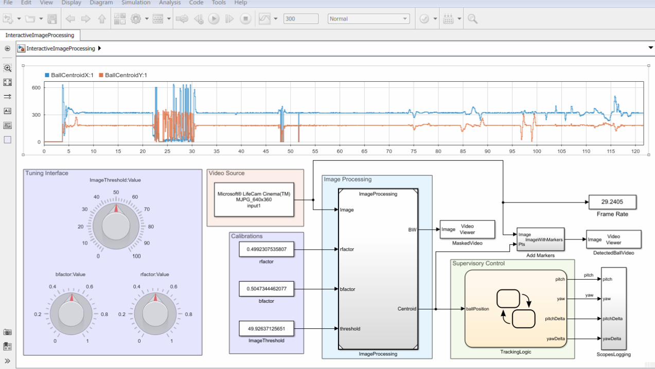
Model-Based Design Application
▪ Rotate a camera to track an object
▪ Computer vision application
▪ Closed-loop motor control
+ +
21

22
What questions do we want to answer?
▪ Can I get the closed loop response I need?
▪ What current will my motor draw during operation?
▪ Does my system still work if component values change?
▪ What if…?

23
Steps in the process
1. Model the motor
2. Model the speed controller
3. Refine the motor model using measured data
4. Model the supervisory logic
5. Validate and integrate the image processing algorithm
6. Deploy the control model to hardware
At each stage: Simulate the model

26
Steps in the process
✓ Model the motor
✓ Model the speed controller
3. Refine the motor model using measured data
4. Model the supervisory logic
5. Validate and integrate the image processing algorithm
6. Deploy the control model to hardware
At each stage: Simulate the model

27
Parameter Estimation

28
Steps in the process
✓ Model the motor
✓ Model the speed controller
✓ Refine the motor model using measured data
4. Model the supervisory logic
5. Validate and integrate the image processing algorithm
6. Deploy the control model to hardware
At each stage: Simulate the model
30
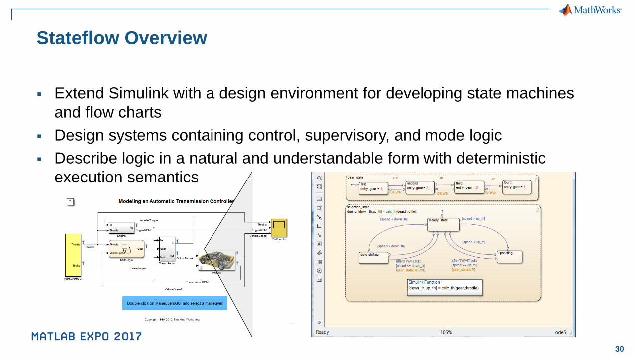
Stateflow Overview
▪ Extend Simulink with a design environment for developing state machines
and flow charts
▪ Design systems containing control, supervisory, and mode logic
▪ Describe logic in a natural and understandable form with deterministic
execution semantics
31
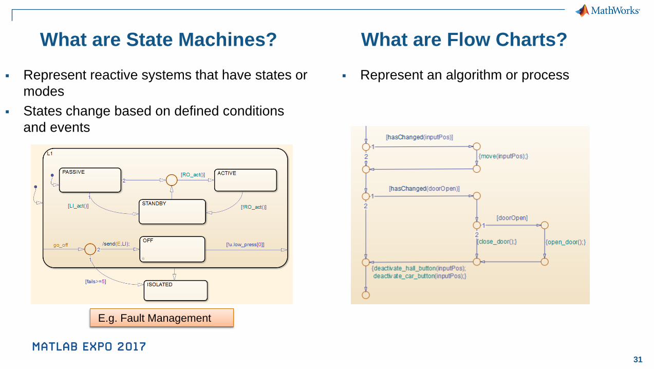
What are State Machines?
▪ Represent an algorithm or process▪ Represent reactive systems that have states or
modes
▪ States change based on defined conditions
and events
What are Flow Charts?
E.g. Fault Management
33
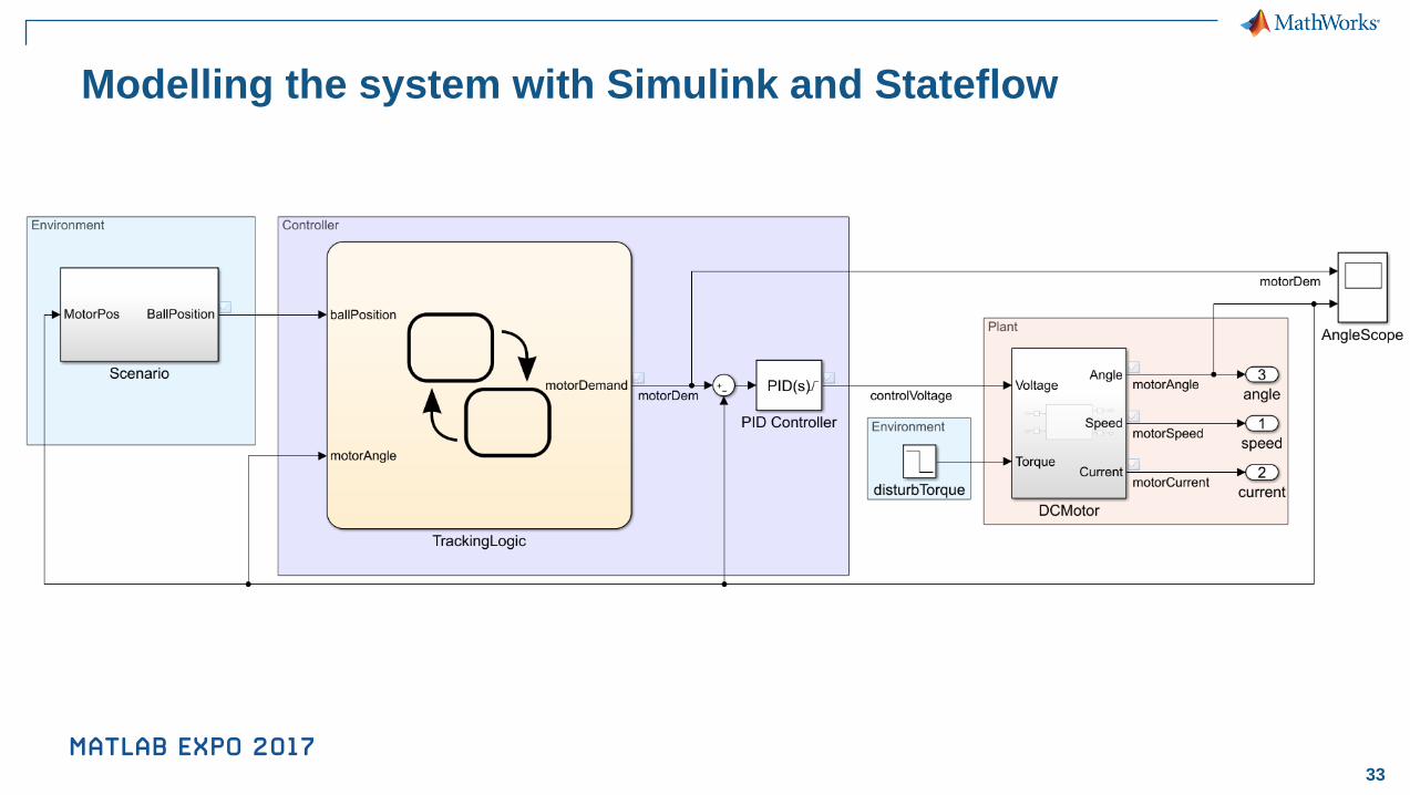
Modelling the system with Simulink and Stateflow

34
Next steps in the process
✓ Model the motor
✓ Model the speed controller
✓ Refine the motor model using measured data
✓ Model the supervisory logic
5. Validate and integrate the image processing algorithm
6. Deploy the control model to hardware
✓ Simulate the model
Visit the
Demo
Stations!

35
Conclusions
▪ Modelling and simulation gives you insight to make smarter decisions,
earlier
▪ Simulink allows you to model the complete system in a single environment
▪ Accelerate your simulation work with the power of MATLAB

36
Solar Impulse Develops Advanced
Solar-Powered Airplane
• Key design decisions
made early
• Vital pilot training
enabled
• Models reused and
shared throughout
development
“Simulations with MATLAB and Simulink were essential to assessing
feasibility and evaluating broad design tradeoffs as well as making
detailed design decisions—like the size of control surfaces and the
vertical tail—that directly affect aircraft dynamics and handling
qualities.”
–Ralph Paul, Solar Impulse