Embed Size (px)
Citation preview

Introduction to S88Introduction to S88For the improvement of the design of batch systemsFor the improvement of the design of batch systems


Introduction to S88 For the improvement of the design of batch systems
JBF

List of authors and editors Members and affiliation (titles are omitted) [in order of Japanese syllabary] Izu Kazumi Kureha Techno Eng Co., Ltd. Itoh Toshiaki Nagoya Institute of Technology Iwane Nobuhisa Mitsui Chemicals, Inc. Kuwatani Motoichi Yokogawa Electric Corporation Sakai Tsuyoshi Yamatake Corporation Shinoda Takuya Yokogawa Electric Corporation Sugiura Akitoshi Morinaga Engineering Co., Ltd. Takayama Hitoshi Yamatake Corporation Teiji Kitajima Tokyo Univ. of Agriculture & Technology Tsukamoto Yasuhiro Mitsui Chemicals, Inc. Nishimoto Yoshitaka Mitsui Chemicals, Inc. Nozato Kazuna Hitachi High-Technologies Corporation Fujisaku Norio Hitachi High-Technologies Corporation Fuchino Tetsuo Tokyo Institute of Technology Hoshi Hirokazu Kureha Techno Eng co.,Ltd. Mikami Yasuo Yamatake Corporation Wakiyama Noboru Yokogawa Electric Corporation Translated by David W. Brown Tokyo Institute of Technology
Copyright © 2007 JBF, All rights reserved.

Contents Preface Foreword 1. Issues related to production sites 1.1 Batch Plant concepts and the problems of batch system design (survey results) 1.2 Issues of increasing batch system remodelling 1.3 Issues of batch system design regarding existing equipment 1.4 Issues of batch system design regarding Research & Development 1.5 Issues of global development and of reducing the development period 2. Batch system design with the S88 standard 2.1 Models handled by S88
2.1.1 Process model 2.1.2 Physical model 2.1.3 Procedural control model
2.2 Elements and mapping of the recipe procedure and of the process cell 2.3 Relevance of the S88 standardized method 2.4 Influence on design activities 3 Examples of functional specifications 3.1 Product based specifications 3.2 Equipment based specifications 3.3 Common specifications Conclusion Appendix A. Batch control – Part 1: Models and Terminology Explanation (JIS C 1807:2002 Batch Control – Part 1: model and terminology, Excerpt from a publication of the Japanese Standards Association) 1. Context and purpose of establishment 2. The four models and the independences between these models 3. The four types of recipes and their corresponding fields Appendix B. Contribution: “Product Development and Recipe Engineering”, Toshiaki Itoh, Nagoya Institute of Technology 1. Reduction of product life and changes in engineering duties 2. Recipe engineering 3. Technological challenges and state of R&D in relation with recipe engineering 4. Industrial limitations that have been overcome with recipe engineering References
122334
5667
10121316
17192123
29
32323335
3737384041
43


Preface In December 2000, JBF set to work on the publication of “Introduction to S88” as one of our work group activities. Its purpose was to help promote the understanding of S88, which was far behind in Japan. The Japanese version was completed in March, 2004, and JBF started distributing it for free on the website. At the WBF held in Chicago in April of 2004, after presenting this publication as the annual report of JBF, Mr. Velumani Pillai and many others suggested translating and publishing the English version so as to inform the contents to the Batch beginners all over the world. We are happy to be able to publish the English translation here, with Mr. David Brown from Canada, a graduate student at Tokyo Institute of Technology, as the translator. We are deeply indebted to Mr. Lynn Craig and Mr. Jean Vieille of WBF who were so kind as to help us with the look-over of the contents. They gave us valuable advice. Also, according to experts of WBF who read the draft, the Equipment Module in the book was a Control Module. It is shown in the figure below, which is presented by Mr. Craig in the Tutorial of WBF. Mr. Craig gave us many instructive comments, some of which we reflected in the text. However, we could not adopt all of them as it would have affected the total organization of the text. It is one example of a practical application based on a simple model, and we hope that this book will be useful for many S88 beginners of the world. Many thanks to JSPS (Japan Society for the Promotion of Science) and Process System Engineering 143 Committee that have supported us financially. In particular, we thank WBF for contributing substantially to the publication of the book. Akitoshi Sugiura Chairman of JBF Tokyo, Japan March 2007

(L. Craig, WBF 2005 Tutorial: An S88 Overview)

Foreword To all of those who are not yet familiar with the S88 Standard The S88 standard is of interest for the improvement of batch system design. Generally, however, fundamental understanding of answers to questions related to S88 such as “what is S88?” and “what kind of merits does it have?” are still lacking. This is why, in order to make an easily comprehensible introduction, this document which aims to deepen the understanding of S88, was written with as many different perspectives as possible on S88. The readers to whom this is addressed If you have been involved in batch process production, even if only in batch system construction, operation, or maintenance, and if you have had a bitter experience, then by all means, please read this document. Of course those of you who are thinking about starting to study batch systems are also invited to read this document. What is S88? S88 is a generic term for an international standard relating to batch systems, IEC61512. It was begun as part of the ISA’s standardization activity started in 1988,to solve four fundamental problems regarding batch control. • There was no prescribed form of batch control (it is now accepted everywhere and by
everyone). • It was hard to explain to vendors what we would like to do with batch processes (lack of
common terminology to explain). • Building batch control systems required considerable labour (and is time consuming). • Putting together the control systems of several manufacturers into one system was a
painful (if not hellish) task for engineers. S88 was written to resolve these problems and has been accepted as an international standard, including for Japanese Industrial Standards (JIS). There are a lot of merits to adopting S88. The object of the first chapter is not to present solutions to all the problems related to production sites, but S88 does hint towards the following solutions. • With standardization and reuse, it can assure cost reduction as well as lead time shortening
(especially remodelling time). • Technology transfers are made easier. • It lessens the burden of having to deal with control systems from different manufacturers.

It is rather difficult to clearly understand what S88 is. One of the reasons for this is the terminology of S88. As much as possible, this document makes use of simple expressions and concrete examples. In order to understand the thinking behind S88, the explanation of an apple juice production process is used as an example. However, the production process presented in this document is fictitious. Please keep in mind that the object of this example is restricted to providing a simple explanation to S88 and that it completely differs from the actual foodstuff industry production process.
We hope that this document will be of help to you.

1
Chapter 1 1. Issues related to production sites
1.1 Batch Plant concepts and the problems of batch system design (survey results) 1.2 Issues of increasing batch system remodeling 1.3 Issues of batch system design regarding existing equipment 1.4 Issues of batch system design regarding Research & Development 1.5 Issues of global development and of reducing the development period

2
1. Issues related to production sites 1.1 Batch Plant concepts and the problems of batch system design (survey
results) A survey of the 17th workshop of the Process Systems Engineering 143rd (PSE143) committee was conducted by the Japan Society for the Promotion of Science (JSPS). The answers to the survey entitled “Batch Plant Concepts” have been compiled as follows: • Batch plants account for a little less than 50 % of the production of more than half of the
industries. • Overall, 45% of these batch plants are single path structured, while the rest are complex
multi-path and/or network structured. • Single product plants account for about 30 % of the total, while the rest produce multiple
products. For most types of industries, there are over 100 varieties for a single product, and this number can in some cases reach 3000 varieties. In addition, in 85 % of the plants, product or variety changes occur.
• 73 % of batch cycles take under one day, but there are also examples in the foodstuff and pharmaceutical industries where they extend to as long as 3 weeks. In most cases, these operations are handled by the control room alone, or in coordination between the site and the control room.
Also, in regard to “Issues of batch system design”, numerous concerns such as “it is difficult to change or to remodel the existing system” and “standardization of design procedures is slow” have been raised. Therefore the concrete example of “problems of production sites” will be presented. 1.2 Issues of increasing batch system remodeling When several varieties of a product are produced in one process sequence, it appears to be often the case that formal process design is done by selecting the unit sequences that may apply to all varieties, and by passing up on the processes which do not. When, the control system designer has made full use of the DCS capacities at the time of introduction, adding a unit sequence in some cases, leaves him no choice but to resort to manual operation because the DCS is not sufficiently adapted to this situation (Fig. 1.1). Assuming that the sequences required for every variety of a product are implemented in a reusable unit, it becomes easy to simultaneously reassign the processing order and increase capacity without problems. Furthermore, if key parts of the unit sequence can be operated simultaneously (in parallel) it is possible to increase “equipment turnover”, and productivity will improve rapidly. In addition, when considering DCS upgrading, even for the same manufacturer, there are situations in which programming languages differ for every type of machine and the code must be entirely rewritten. For instance, would it be possible for some sort of system to automatically convert a text file defining a program directly to a required language?

3
Fig. 1.1 Problems with addition of unit sequences
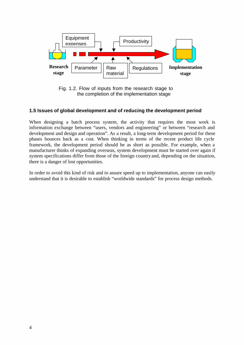
1.3 Issues of batch system design regarding existing equipment Within batch plants, product changes may be radical and in many cases, remodeling the process is required time after time. Rational remodeling implies that the existing equipment should be utilized efficiently, but there are cases when the use of new equipment is unavoidable. This might be for reasons such as differing control system specifications depending on the vendor, or the impossibility of adapting the existing application. When control system specifications are standardized, the reuse ratio of equipment also increases; in addition, with the improvement of existing equipment + a, simple and short period “copy plant” construction will probably also become a possibility. Furthermore, because standardization can prevent the batch process design philosophy from being overly individual, it is thought that major problems will not occur, even when the people in charge of design are replaced because of reshuffling, etc. Control system specification standardization is desirable even from the viewpoint of passing on technical knowledge. 1.4 Issues of batch system design regarding Research & Development The operations at the research stage (flask level) are mainly done manually and there are practically no examples of simultaneous operations involving several flasks. “Quality” is strongly emphasized, which makes it possible to discover design solutions where “safety” and “cost” are neglected. However, at the implementation stage, the question “what should be done to operate several pieces of equipment safely and efficiently?” becomes an important issue. What with the modification of parameters involved during scale-up, restrictions related to raw materials, laws and regulations, and specific information related to equipment (Fig. 1.2), is there an ideal process design method for maximizing safety and economically making a product of the same quality that came from the research stage?
Feed A
Feed B
Heating
Feed C
Reaction
Insufficiently adapted
4
Fig. 1.2. Flow of inputs from the research stage to the completion of the implementation stage
1.5 Issues of global development and of reducing the development period When designing a batch process system, the activity that requires the most work is information exchange between “users, vendors and engineering” or between “research and development and design and operation”. As a result, a long-term development period for these phases bounces back as a cost. When thinking in terms of the recent product life cycle framework, the development period should be as short as possible. For example, when a manufacturer thinks of expanding overseas, system development must be started over again if system specifications differ from those of the foreign country and, depending on the situation, there is a danger of lost opportunities. In order to avoid this kind of risk and to assure speed up to implementation, anyone can easily understand that it is desirable to establish “worldwide standards” for process design methods.
Research stage
Equipment expenses Productivity
Parameters
Raw materials
Regulations Implementation stage

5
Chapter 2 2. Batch system design with the S88 standard
2.1 Models handled by S88 2.1.1 Process model 2.1.2 Physical model 2.1.3 Procedural control model
2.2 Elements and mapping of the recipe procedure and of the process cell 2.3 Relevance of the S88 standardized method 2.4 Influence on design activities

6
2. Batch system design with the S88 standard One of the goals of the S88 batch system design standardization is for anyone to able to design a batch system within the same framework by adopting this modeling concept. Another purpose which can be cited is to solve the problem of remodeling the control system’s software when product changes occur. Within S88, the solution to this problem is assured by separating “the production procedures that depend on the product” from “control that depends on equipment”. Section 2.2 “Elements and mapping of the recipe procedure and of the process cell”, explains this in detail.
2.1 Models handled by S88 There are four especially important types of models: • The process model, which will be explained by looking at the aspects of the chemical and
physical changes, etc. • The physical model, which will be explained by looking at the aspects of the hardware • The procedural control model, which will be explained by looking at the aspects of the
software • The Activity model
2.1.1 Process model The process model can be defined by the sentence: “what should be done in order to make a given substance?” Usually when something is synthesized or manufactured, chemical and physical changes, such as what raw materials to use and in what kind of ratio, whether to use a catalyst, up to what to degree should temperature be increased, etc., are gradually noted down. This is a process model. Let us consider the process model of the addition of vitamin C to apple juice as an example (Fig. 2.1). It does not convey the concept of equipment, because the only activities described are how the substances are chemically and physically modified until they become a product. The expressions introduced for actions indicating changes such as ”addition of vitamin C”, etc. remain the same from the laboratory level to the commercial plant level.

7
Fig. 2.1 Process model of the addition of vitamin C to apple juice 2.1.2 Physical model When the process model is completed, the construction of the plant in which vitamin C is actually added to apple juice is done on the basis of this model. Other than the construction of a new plant, the process of adding vitamin C could also be designed for an existing plant; however this scenario will be replaced by a facility capability matching scenario. It is possible to mix the Raw apple juice, the aqueous sugar solution, and vitamin C into one mixing tank, but in this case it has been decided that the process would involve first making apple juice by mixing the Raw apple juice and the aqueous sugar solution together, and by adding vitamin C to the apple juice afterwards (Fig 2.2). The details of the bottling process are omitted.
Kg 48 Vitamin C Kg 476 Sugar solution Kg 476 Raw apple juice
Unit Quantity Raw material
Raw material consumption table (1000kg basis)
Feed
Addition
Agitation cooling
Agitation
Bottling
Sugar solution 476Kg
Raw apple juice 476Kg
Vitamin C 48Kg
Apple juice 952Kg
Apple juice supplemented with Vitamin C 1000Kg
Agitate until homogeneous blending is
achieved (standard: 15 minutes) Cool down to 15
Celsius
Agitate until concentration is constant
(in general: 10 minutes)
Bottled Apple juice supplemented with Vitamin C 1000Kg

8
Fig. 2.2 Apple juice production plant Within the physical model, the plant is divided into different sections. The plant as a whole is designated as the process cell; the process cell is broken down into units, and the units, in turn, into smaller modules called equipment modules and control modules (Fig. 2.3 & 2.4). It can be noted that the equipment modules that feed sugar solution and raw apple juice, each serve a single function in this case. They are assembled from control modules that carry out agitation and temperature control by driving the valves, the pumps and the piping. The key to generalizing and reusing software for batch control is the way equipment and control modules are linked together.
Process CellUnit
Unit
Addition Tank
Mixing Tank 1
To bottling process
Raw apple juice tank
Sugar solution tank
Vitamin C Vessel

9
Fig. 2.3 Divisions within a unit
Equipment module
Fig. 2.4 Divisions within equipment
Raw apple juice
Valve Flow meter Pump
Control module
Raw apple juice feed line
Mixing Tank 1
Unit
Raw apple juice feed line
Raw apple juice tank
Sugar solution tank
Agitator
Temperature control jacket
Liquid transfer line
Equipment module
Sugar solution feed line

10
2.1.3 Procedural control model When the physical model is completed, the procedure of apple juice production is defined from the process model and the physical model as follows:
1. Supply 476 kg of Raw the apple juice 2. Supply 476 kg of sugar solution Feed 3. Agitate for 15 minutes Apple juice mixing 4. Cool to 15 °C Cooling 5. Inject liquid Liquid transfer 6. Supply 48 kg of vitamin C solution Addition 7. Agitate for 10 minutes Liquid transfer Vitamin C addition 8. Add to storage tank
The procedure of apple juice production can be grossly divided into two unit procedures relating to the units involved in this process: the unit procedure of mixing the raw apple juice and the sugar solution in the mixing tank one, and the procedure of adding vitamin C in the addition tank. The unit procedure of mixing the apple juice is further broken down into the three operations of preparing the raw materials, and of cooling and injecting the liquid mixture. The operation of preparing the materials is divided into three phases: preparing the raw apple juice, preparing the aqueous sugar solution and agitation. In this way it is possible to establish a hierarchy within the procedure between the more general links and the more detailed links. Fig. 2.5 shows an example of the PFC (Procedural Function Chart) utilized for the apple juice production procedure. This type of hierarchical procedure is called the Procedural Control Model. Since the process model, the physical model, and the procedural control model are closely related, a modification to either one of these models will have an impact on the other models. For instance, in the preceding explanation of the physical model, the plant was formed of a mixing tank and a second “addition” tank, but it is also possible to add vitamin C to apple juice using only the mixing tank. If this was the case, because “liquid transfer” from the mixing tank to the addition tank would become unnecessary, the procedural control model would be modified. In addition should one want to simplify the procedure so as to shorten batch time etc., there are also instances when the physical model (plant modification) is modified. When batch system design is done with the S88 standard, one is conscious of these models. The design of the physical model (= plant design) and the design of the procedural control model (= control procedure design) are done by use of the process model, but since they all mutually have an impact on each other, for the design to be appropriate, it is necessary to track and rectify the respective designs depending on the design information of each model.

11
Apple juice mixing(Unit procedure)
Addition of vitamin C(Unit procedure)
Apple Juice with vitamin C
+
ProcedureApple juice with
vitamin C
+
+
Feed(Operation)
Cooling(Operation)
+
Unit ProcedureApple juice mixing
+
Liquid transfer(Operation)
+
+
Apple juice
Addition(Operation)
Liquid transfer(Operation)
Apple Juice with vitamin C
+
Unit ProcedureAddition of vitamin C
+
+
Addition of vitamin C(Phase)
Agitation(Phase)
OperationAddition
+
Liquid transfer(Phase)
OperationLiquid transfer
+
Liquid transfer(Phase)
OperationLiquid transfer
+
Cooling (Phase)
OperationCooling
+
Sugar solution feed(Phase)
Raw apple juice feed(Phase)
OperationFeed
Agitation(Phase)
+
Fig.2.5 PFC of the example of apple juice production procedure

12
Procedure
Unit procedure
Unit operation
Phase
Process cell
Unit
Equipmentmodule
Controlmodule
Procedural control model Physical model
Recipe procedure
Command
Resourceallocation
Equipm
ent control
2.2 Elements and mapping of the recipe procedure and of the process cell
Fig. 2.6 shows the relation between the procedural control model and the physical model of the S88 standard. Here the behavior of equipment control, such as for feed, agitation, temperature control and liquid transfer, is specific to the process cell. The production procedure is described with the procedural control model. It is called the recipe procedure. In the example of the apple juice production process, the mapping which is done at the lowest level (the phase) is that of the equipment used in the feed lines, for agitation, etc. In accordance with the recipe procedure, the control system automatically indicates the batch operational time to the equipment, and production is undertaken. In this way, by implementing the equipment control to the recipe procedure and a separate control system, it is possible to change the control action by simply modifying the procedural control model. In regard to resource allocation for contamination prevention and the optimal distribution of resources, the implementation of divisions is similar to that of the recipe procedure: it is possible to change the allocation of resources by simply modifying the procedural control model. In addition, assuming that the production procedure differs for several products, it would be sufficient to simply modify the recipe procedure when the utilized equipments are the same.
Fig. 2.6 Example of elements and mapping of the recipe procedure and of the process cell

13
2.3 Relevance of the S88 standardized method Formerly with batch control, the procedure only consisted in modifying specifications (what was called the recipe generally indicated the specifications of every unique product), but when procedure modifications occur, software remodelling is often involved. With S88, the recipe not only includes the specification of every unique product, but also those of the production procedure as is defined in Fig. 2.5 (= recipe procedure), which makes it a means of thinking on how to lower software costs. Let us reflect on the case where the process is changed into a new manufacturing method in order to shorten processing time. In Fig. 2.5, the raw apple juice has been supplied after the sugar solution, but in Fig. 2.7 to shorten processing time, it is modified into a manufacturing method in which the two raw materials are supplied simultaneously. With the hierarchical structure of S88, the part that is modified is only the feed process for apple juice mixing, and it is found that the impact on software modifications is very limited. With this technique, if another additive were added after the addition of vitamin C, or if the trial manufacture of another juice took place, software modification would be completed with minimum changes. By using this type of modeling technique it becomes possible to organize the separation of product and equipment control, to make flexible use of the product (recipe) for the implementation of the control system, to simplify software modifications by employing the equipment control mapping technique, and to rapidly trial test a new product and introduce it to the market. Note that if the phys ical model and the procedural control model are designed as in Fig. 2.8, it becomes impossible to prepare the sugar solution and the Raw apple juice in series. It is important to design the phases and the equipment modules with appropriate divisions.

14
Apple juice mixing(Unit procedure)
Addition of vitamin C(Unit procedure)
Apple Juice with vitamin C
+
ProcedureApple juice with
vitamin C
+
+
Feed(Operation)
Cooling(Operation)
+
Unit ProcedureApple juice mixing
+
Liquid transfer(Operation)
+
+
Apple juice
Addition(Operation)
Liquid transfer(Operation)
Apple Juice with vitamin C
+
Unit ProcedureAddition of vitamin C
+
+
Addition of vitamin C(Phase)
Agitation(Phase)
OperationAddition
+
Liquid transfer(Phase)
OperationLiquid transfer
+
Liquid transfer(Phase)
OperationLiquid transfer
+
Cooling (Phase)
OperationCooling
+
Parallel ProcessingOperationFeed
+
Sugar solution feed(Phase)
Agitation(Phase)
Raw apple juice feed(Phase)
Fig. 2.7 Recipe procedure after batch time shortening

15
Apple juice mixing(Unit procedure)
Addition of vitamin C(Unit procedure)
Apple Juice with vitamin C
+
ProcedureApple juice with
vitamin C
+
+
Feed(Operation)
Cooling(Operation)
+
Unit ProcedureApple juice mixing
+
Liquid transfer(Operation)
+
+
Apple juice
Liquid transfer(Phase)
OperationLiquid transfer
+
Cooling (Phase)
OperationCooling
+
Sugar solution,raw apple juice mixing
(Phase)
OperationFeed
Agitation(Phase)
+
Agitator
Liquid transfer line
Temperature control jacket
Raw apple juicefeed line
Sugar solutionfeed line
Raw applejuice tank
Sugar solutiontank
Mixing tank 1
Does not correspond to a preparation in parallel
Fig. 2.8 Example of an equipment/recipe procedure which
is not designed with appropriate divisions

16
Physical model depended procedure
Product and facility planning
Constraints
Processspecification
General recipe
Procedural control task
Equipment design
diagram
Equipment relation diagram
P&ID
Master recipe
Common specification-operation-exceptional handling policy-shared resource-route management-equipment synchronization
Recipedesign
Information required for implementation
Helpful information towards implementation
Activity
Input/Output
Unitsupervision
Processcontrol
Controlrecipe
Design Implementation
Physicalmodeldesign
Proceduralcontrol model
design
Equipmentcontroldesign
Processmodeldesign
Recipemanagement
Productionplanning andscheduling
Productioninformation
management
Processmanagement
2.4 Influence on design activities A possible design with the S88 standard is summarized in Fig. 2.9. The unit design (the design of the physical model) which is used for actual production, is done on the basis of the process model. The design of the procedure that is prerequisite to designating the use of these units (the design of the procedural control model) is conducted simultaneously. With this design, the P&ID for the plant design and the plan which is annexed to it, and the equipment module design diagram for the implementation of plant operation/function to the control system, are completed along with the basic recipe which defines what kind of procedure should be used to operate the plant. In chapter 3 specific examples of the specifications which make use of these standard techniques will be given.
Fig. 2.9 Engineering with the S88 method and implementation to control systems

17
Chapter 3 3. Examples of functional specifications
3.1 Product based specifications 3.2 Equipment based specifications 3.3 Common specifications

18
3. Examples of functional specifications In this section, specific examples of the specifications which make use of the standard techniques introduced in chapter 2 will be given. The specifications can be broadly divided into 3 types.
• Product based specifications
These are described from the standpoint of processing the raw materials until they become a product. They specifically explain with what type of procedure and what type of raw material processing should be conducted.
• Equipment based specifications These explain with what type of equipment production should be done for the processing specifically expressed with the product based specifications.
• Common specifications These explain what the necessary common items are, for constructing the control system.
An example of the contents of the specifications is shown in example 3.1.
Apple juice production facility control system specification < Table > 1. Product based specifications 1. Process 2. Apple juice production process 1. Production process of adding vitamin C to the apple juice 3. Recipe 1. Apple juice production recipe 2. Production recipe of adding vitamin C to the apple juice 2. Equipment based specifications 1. Equipment diagrams 1. Equipment level diagram: Unit 1 2. Equipment level diagram: Unit 2 (omitted) 3. Equipment level diagram: Unit 3 (omitted) 4. Equipment level diagram: Unit 4 (omitted) 2. Equipment module design diagram 1. EM1 (sugar solution feed equipment module control) 2. EM2 (vitamin C supple equipment module control) (omitted)
3. Common specifications 1. Operation specifications 2. Approach for handling perturbations 3. Common resources 4. Route management 5. Equipment synchronization
REV___________ REMARKS________________ PJDocNo. _________TITLE_______ BLOCK CODE _____ PSE143-JBF-standardWG2002-01 Example 3.1 Contents of the specifications
Apple juice production facility control system specification < Contents >
Product based specifications 1. Process 2. Apple juice production process 1. Production process of adding vitamin C to the apple juice 3. Recipe 1. Apple juice production recipe 2. Production recipe of adding vitamin C to the apple juice
Equipment based specifications 1. Equipment diagrams 1. Equipment level diagram: Unit 1 2. Equipment level diagram: Unit 2 (omitted) 3. Equipment level diagram: Unit 3 (omitted) 4. Equipment level diagram: Unit 4 (omitted) 2. Equipment module design diagram 1. EM1 (sugar solution feed equipment module control) 2. EM2 (vitamin C supple equipment module control) (omitted)
Common specifications 1. Operation specifications 2. Approach for handling perturbations 3. Common resources 4. Route management 5. Equipment synchronization
REV___________ REMARKS_____________PJDocNo. _________TITLE_______ BLOCK CODE _____ PSE143-JBF-standardWG2002-01

19
3.1 Product based specifications Example 3.2 is an example of specifications seen from the aspects of the process such as chemical reactions and physical changes. They do not convey the concept of equipments, because the only points which are described is to express what should be done in order to make a certain substance, in terms of chemical and physical changes to the substances until they become a product. The expressions introduced for actions indicating changes such as “injecting liquid”, etc. remain the same from the laboratory level to the commercial plant level.
Example 3.2 Apple juice production process specifications (based on S88-3 PPC)
Apple juice Production process Raw apple juice
476kg Sugar solution
476kg
Storage tank
Agitation-Cooling
Apple juice 952kg
Vitamin C 48kg
Apple juice supplemented with vitamin C
1000kg
Apple juice supplemented with vitamin C
1000kg
Agitate until mixed homogeneously (standard: 15 min utes),cool down to 15℃
Agitate until concentration is constant (standard: 10 minutes).
Raw Material Consumption Table (1000kg basis)
kg 48 Vitamin C
kg 476 Sugar solution
kg 476 Raw apple juice
Unit Quantity Raw material
REV REMARKS PJDocNO. TITLE BLOCK CODE PSE143-JBF-standard WG2002-01
designates the raw materials,the intermediate products and the finished product.
designates the respective process operation.
designates the order of process operations. The raw material consumption table to make 1 ton of the products is indicated in the right half.
Agitation
Addition
Input/ Output

20
Example 3.3 is an example of the general recipe for apple juice production. The right half is an example of the procedural control model.
PSE143-JBF-標準化WG2002-01
BLOCK CODETITLEPJDocNo.REMARKSREV
Apple juice product recipe specifications
【Header】 PFC
【Formula 】
【Product Standard】
Product name ××(development code R101)Characteristic The (R100) type of apple juice product
supplemented with vitamin C
SignSignFirst issue××0
Person in
charge
Content of
correct-ions
Appro-val
Content of corrections Approvaldate
Revision number
1,440 kg480 kgVitamin C
14,280 kg4,760 kgSugar solution
14,280 kg4,760 kgRaw apple juice
Mixing tank 2(30t)
Mixing tank 1(10t)
Name of raw material
《raw materials》
《operations》
15℃15℃Cooling
10Min10MinMixing 2
15Min15MinMixing 1
Mixing tank 2Mixing tank 1Name of operation
○○○
×××
Standard value
JIS○○○○
JIS××××
Measuring metodItem
Procedure
リンゴジュース調合単位手順(Unit Procedure)
Apple juice mixingUnit Procedure
ビタミンC添加単位手順(Unit Procedure)
Addition of Vitamin-CUnit Procedure
Unit Procedure
Apple juice mixing
添加単位操作(Operation)
AdditionOperation
送液単位操作(Operation)Liquid transfer
Operation
Apple juice with Vitamin C
Unit Procedure
Addition of vitamin-C
仕込単位操作(Operation)
FeedOperation
冷却単位操作(Operation)
CoolingOperation
Apple juice
送液単位操作(Operation)
Liquid transferOperation
Sugar solution feedPhase
Cooling
冷却フェーズ(Phase)
CoolingPhase
攪拌フェーズ(Phase)
AgitationPhase
送液フェーズ(Phase)Liquid transfer
Phase
Operation Feed
リンゴ原液仕込フェーズ(Phase)
Raw apple juice feedPhase
送液フェーズ(Phase)Liquid transfer
Phase
Liquid transfer
ビタミンC添加フェーズ(Phase)
Addition of Vitamin-CPhase
攪拌フェーズ(Phase)
AgitationPhase
Operation
Operation
Apple juice with Vitamin C
Apple juice with vitamin C
Liquid transferOperation
AdditionOperation
Example 3.3 Apple juice product recipe specifications (based on S88-2 PFC)

21
3.2 Equipment based specifications Example 3.4 shows the hierarchy from the perspective of the hardware used for the actual production of the product defined with the process model. The key to considering the possibility of generalizing and reusing software is in the method of linking equipment modules together.
Example 3.4 Equipment level diagram
Temperature control valve 1
Cooling
Thermometer 1
Temperature control module 1
Mixing tank 1
UNIT 1
Cross valve 1
Agitator 1
Outlet module 1
Equipment level diagram: Unit 1
(Unit) (Equipment Module) (Control Module)
Unit 1 Mixing tank 1 Agitator 1 Temperature control module 1 Temperature control valve 1 Thermometer 1 Outlet module 1 Cross valve 1 Unit 1 decomposes into the mixing
tank 1, the temperature control and the outlet equipment modules
REV___________ REMARKS________________ PJDocNo. _________TITLE_______ BLOCK CODE _____ PSE143-JBF-standardWG2002-01

22
Example 3.5 describes the specifications of an equipment module control. Inputs are indicated in a prescribed format on the left side, outputs are shown on the right side, and in the central part the processing which is necessary is described. Other equipment module controls should be described in the same manner.
Example 3.5 Equipment module control specifications
sugar solution feed equipment module control EM1
Sequence
1.Secure line2.Open valve3.Start pump/Verify answer4.Start addition count5.Addition count up6.Close valve7.Stop pump
It is required that it be possible to operate multiple units (units 1 and 3) in parallel simultaneously.Before stopping the pump, verify that there are no demands left to satisfy
Sugar solutiontank
Automatic/semi-automaticmode switch
From the unit Start feed operation Quantity supplied Interrupt/restart operation
Sugar solution tank is cut off Pump trip Start pump signal Flow meter 1 & 2 signal Open valve answer signal
Operation mode specs Operation conditions specs. Weighed result report
To the unit Notification of end of feed Notification of abnormal end of feed Notification of weighed dataresults
Start/stop pump directive Open/close valve directive
Abnormal quantity supplied Pump trip Sugar solution tank is cut off
Stop pump Close valve Do not reset batch counter (to be manually reset by the operator)
Feed destination Actual feed value
FQ001
FQ002
BLOCK CODE TITLEPJDocNo. REMARKS REV PSE143-JBF-Standardization WG2002-01
PROCESS OUTPUT HMI input HMI output
INPUT
From other equipment module To other equipment module
Recipe parameter
Collect data results
Field output signal
Field input signal
Handling abnormal conditions Warning handling
Function

23
3.3 Common specifications The necessary common items which partly relate to the construction of the control system with S88 are shown bellow. Example 3.6 is the sequence state transition: it displays what types of state transitions are possible with “push buttons” and the likes, with regard to “the state” of the process.
Example 3.6 Operation specifications
REV___________ REMARKS________________ PJDocNo. _________TITLE_______ BLOCK CODE _____PSE143-JBF-standardWG2002-01
Reset button Reset button
Start button Stop button
Start button
Start button
In Standby
Halted Halted in an abnormal situation
Operating
Automatic operation transition
Automatic operation transition
Operation specifications
Mode Each unit / equipment module has three modes of automatic, semi-automatic, or manual operation.
State transitions Each unit / equipment module has four possible states as mentioned below.
Manual intervention Usually (whatever the mode is), manual intervention operations are possible.
1
2
3
4
4
5
6 6

24
Example 3.7 describes the method of thinking of the correspondence between the control units during an emergency shutdown operation conducted either by the operator or an automatic sequence abnormal stop procedure.
Example 3.7 Specifications for exception handling
Approach to exception handling
1. An abnormal situation refers to conditions for which it becomes necessary to handle automatic sequence emergencies involving automatic sequence congestions or the use of the emergency shutdown button by the operator. The exceptional situation for which the operation is done by manual intervention is not included.
2. Abnormal situation emergency handling
The control system outputs are turned off (process safety aspect - stop rotating machines and close valves).
3. Measures to recover from abnormal situations
The operator on duty restarts the process, after having received from the head person in charge of the process the directive of restoring it from abnormal conditions.
4. Exception handling in halted state
Conversely for an abnormal stop, the output from the control system is not halted, and the state is maintained as it is.
REV___________ REMARKS________________ PJDocNo. _________TITLE_______ BLOCK CODE _____ PSE143-JBF-standardWG2002-01

25
Example 3.8 shows how the equipment modules are rearranged to be used as common resources for multiple units. With this example, the Raw apple juice is used exclusively, and the simultaneous use of the sugar solution is permitted. For equipment modules other than example 3.8, it is necessary to describe each specification with regard to common resources, such as control in series, etc.
Example 3.8 Common resources management specifications
Sugar solution tank
To bottling process
Temperature control
Cooling
Mixing tank 1
Addition tank
Raw apple juice tank
Cooling
Mixing tank 2
Vitamin C Vessel
Common resources
Requirement specifications Possibility of simultaneously preparing the feed of multiple measuring lines Operation of the feed pump continues until the weighed demand for all lines ends (OR control)
Requirement specifications Possibility of exclusively measuring for simultaneous requests from multiple measuring lines Impossibility of interruption failure: “first come first served” (exclusive control)
REV__________ REMARKS_______________ PJDocNo. ________TITLE_______ BLOCK CODE _____PSE143-JBF-standardWG2002-01

26
Example 3.9 shows the possible routes, for one batch, specifying which units in which order material can flow through after considering the physical constraints in various conditions.
Example 3.9 Route management specifications
Route management
Input physical storage (Raw apple juice tank, sugar solution tank)
Mixing tank 1 Mixing tank 2
Vitamin C addition tank
Product storage (to bottling)
REV___________ REMARKS________________ PJDocNo. _________TITLE_______ BLOCK CODE _____PSE143-JBF-standardWG2002-01
1: Route 1 (No addition of vitamin C)2: Route 2 3: Route 3 4: Route 4 (No addition of vitamin C)
1 2 3 4

27
Example 3.10 is a Gantt chart that displays the timing of the delivery of the substances during the unit operations within each unit.
Example 3.10 Synchronous specifications between units
Synchronous specifications between units
REV___________ REMARKS________________ PJDocNo. _________TITLE_______ BLOCK CODE _____PSE143-JBF-standardWG2002-01
Mixing tank
Addition tank
Cooling Liquid transfer Manual cleaning
Feed Addition Agitation Liquid transfer
Empty mixing tank

28

29
Conclusion By now you have probably gained some insight into the answers to “What is S88?”and “What kind of merit does it have?” As expressed in chapter 2, one of the aims of S88, is reusability. Towards this end, the batch plant is divided and arranged in a hierarchy. This allows different dimensions (points of view) where a mapping of “process”, “physical equipment” and “procedural control” is done by making use of modeling techniques. With this it is possible to specifically separate “the production procedures which depend on the product” from “the control which depends on the equipment”, and to solve the issue of reusability. However, from the perspective of studying S88, it is not an overstatement to say that modeling in itself is the largest barrier to understanding S88. This is why this document has tried to explain the aspect of modeling in the easiest possible way.
On the other hand, S88 is not something which shows “How-to” model. It is probably more correct to say that, as a standard, it gives a point of view for modeling. For example, in Fig. 2.3, “separations within a unit”, for which the example of categorizing the physical model is shown, it was explained that “the key to considering the possibility of generalizing and reusing software for batch control is in the way of linking equipment modules together”. However, it is neither written nor is it the purpose of S88 to answer the question: “how should the equipment modules be linked together?” In a certain sense, what corresponds to individual implementation is stipulated as purpose that is left to the user, as a method of captivating the object of modeling towards the realization of reusability, and as a fundamental way of thinking.
We have expressed that this document is focused on explaining modeling, but as is characteristic of introductory handbooks, many details concerning modeling were omitted. In addition, the other parts (for instance, “production information”, “handling exceptions”, “management activity”, “recipe management”, “production control” and “scheduling”) have been stated as examples of specifications, but have mostly not been dealt with. Furthermore for the sake of “easy understanding”, some venturous interpretations have also been added in certain parts of this text. In this sense, the purpose of reading this document was not to entirely understand S88, but to help you make a first step in order read through and understand S88. And we hope that, when you do so, you will find that this introductory document has been of help to you.
Furthermore, appendix A, an excerpt from a publication Batch control – Part 1: model and terminology “JIS C 1807:2002 Batch Control – Part 1: model and terminology” of the Japanese Standards Association is given as a reference. In addition, appendix B: “Product Development and Recipe Engineering” (contribution) is added as an example of a higher-level application.
Lastly, we would like to express our gratitude towards all the members and organizers of JBF (the Japan Batch Forum), and the executives of JBF for the Process Systems Engineering Science 143rd committee starting with the chairman of the committee and each manager of the Japan Society for the Promotion of Science for their support and understanding regarding

30
the working group activities which on the long term have contributed to the publication of “Introduction to S88”.

31
Appendices Appendix A. Batch control – Part 1: model and terminology Explanation (JIS C 1807:2002 Batch Control – Part 1: model and terminology, Excerpt from a publication of the Japanese Standards Association) Appendix B. Contribution: “Product Development and Recipe Engineering”, Toshiaki Itoh, Nagoya Institute of Technology

32
Appendix A. Batch control – Part 1: Models and Terminology Explanation (JIS C 1807:2002 Batch Control – Part 1: Models and Terminology, Excerpt from a publication of the Japanese Standards Association) 1. Context and purpose of establishment ISA (The Instrumentation, Systems, and Automation Society) has played a central role in creating international standards for batch control systems. 1988.10 SP88 (Standard Practices 88) was established by ISA, which corresponds to the WG11 batch control system that was made by IEC TC65/SC65A. In 1995, ISA S88.01 Batch control Part1: Models and Terminology was standardized, and consequently, in 1997 IEC 61512-1 Batch control Part1: Models and Terminology was established. In this context, the workshop No.20 (modeling batch processes for operation management)/WG3 standardization sub-panel of the 143rd Process Systems Engineering committee of the Japan Society for the Promotion of Science (JSPS) evaluated the effectiveness of IEC 61512-1, and because of the merit brought by the standardization of models and terminology, requested the Japan Electric Measuring Instruments Manufacturer's Association to recommend it as a JIS standard. Consequently, by making use of this, the Japan Electric Measuring Instruments Manufacturer's Association which is the window of the domestic measure committee of IEC TC65/SC65A/WG11 has provided the WG batch system standardization examination, and progressed in the task of standardizing Japanese for JIS. In the introduction to IEC 61512-1, the following points are presented as the objective and intention of this standard. The model and the terminology which are defined with this standard are used for the following activities. • Give a clear indication of what should be done in regard to batch production plant design
and operation. • Improve batch production plant control. • Be applicable regardless of the extent of automation. In particular, because of the fact that it is provided with concepts and models which are consistent, this standard terminology for batch production plant and batch control improves the will for mutual understanding between the different parties that are concerned, and makes the following possible: • Shorten the time until the new product reaches the complete production level. • Provide the appropriate tools for vendors to make practical use of batch control. • Assure that users adequately formulate requests. • Enable the control system technicians to be able to develop a recipe without assistance. • Reduce the cost of batch process automation. • Reduce the engineering load over the life cycle.
Also, this standard does not intend the following:

33
• Suggest that it is the only method that exists to introduce or apply batch control. • Force users to give up on methods currently being used with batch processes. • Impede development in the field of batch control. The models which are presented in this standard are assumed to be complete, but it does not matter whether these models are simplified or detailed. It is not possible, however, to omit the classification of the units and the control modules from the physical model. In the same way, it is not possible to omit the general recipe and the control recipe, from the model of the recipe. Specific rules for simplifying or detailing these models are not included in this standard. • Simplifying: It does not matter whether a certain element which is part of the model is
deleted from the model, insofar as the function of the element which maintains the consistency of model still remains.
• Detailing: It does not matter whether a certain element is added to a module, insofar as if an element related to the module is added, the consistency of the original rela tion is maintained.
2. The four models and the independences between these models Four models have been formulated with this standard. Each model illustrates the batch system from the perspective of process design, plant design, instrumentation design, and information management, which corresponds respectively to the process model, the physical model, the procedural control model, and the management activity model. Each model constitutes a hierarchical structure, and there is a corresponding relationship for each class of model. However, each model is independent and this standard does not formulate univocal correspondences. Consequently this implies various implementation methods, broad possibilities of application, and difficulty of verifying interpretations.
1) Process model ...... process design 2) Physical model ...... plant design 3) Procedural control model ...... instrumentation design 4) Management activity model ...... information management
In Fig A.1, an example of the correspondences between models 1), 2) and 3) is shown. In this example for which there are no univocal corresponding relations, it is possible for the phases of the procedural control model to correspond to the units or to the equipment modules of the physical model.

34
Unit Procedure(s) Unit(s) Process
Stage
combined with a
Operation(s) Unit(s) Process Operation
combined with a
Phase(s) Unit(s) Process Action
combined with a
Phase(s) Equipment Module(s)
combined with an
Procedure(s) Process Cell(s) Process
combined with a
provides process functionality to carry out a
provides process functionality to carry out a
provides process functionality to carry out a
provides process functionality to carry out a
provides process functionality to carry out a
Resulting Process
FunctionalityEquipmentProcedural
Elements
Procedural Control Model
Physical Model (Lower
Portion)Process Model
(See Figure 6) (See Figure 2) (See Figure 1)
Process Action
Fig. A.1 Example of correspondences between models With this standard the relationship between the management activity model and the other models is not stipulated. Fig. A.2 is one example of the situational relation between the management activity and the physical model.

35
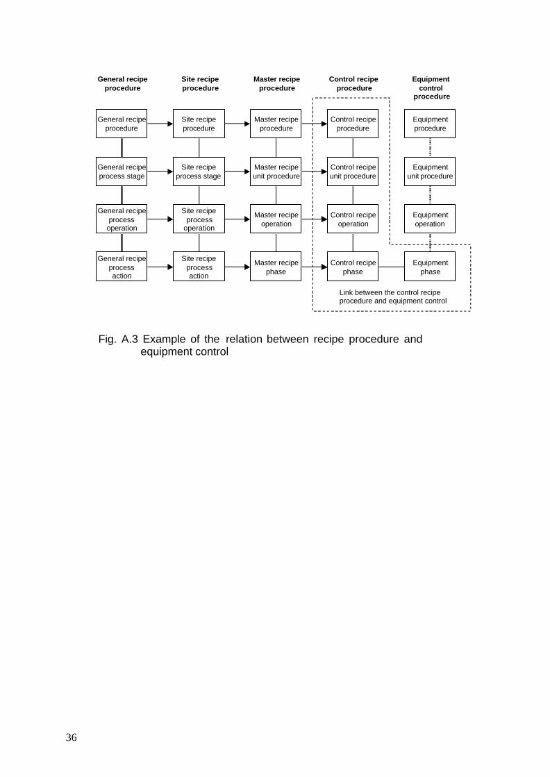
3. The four types of recipes and their corresponding fields In a batch production plant, recipes are what relate the production procedure to the process; recipes are classified into 4 categories. On the upper level the general recipe and the site recipe correspond to the research / enterprise stage and the site stage, and do not imply any specific physical equipment. The general recipe and the control recipe which are subordinate to the previous two, suppose that physical equipments are specified.
1) General Recipe ... does not imply any specific equipment 2) Site Recipe ... does not imply any specific equipment 3) Master Recipe ... implies specific equipment 4) Control Recipe ... implies specific equipment
The recipe procedure of the general recipe and site recipe depend on the process model, the recipe procedure of the master recipe and the control recipe depend on the procedural control model.
Process Control
Unit Supervision
Process Management
Production Planning and Scheduling
Recipe Management
Personnel and Environmental Protection
Production Information Management
Outside the scope of this standard
Area
Process Cell
Enterprise
Unit
Equipment Module
Control Module
Site
May contain
May contain
May contain
May contain
Must contain
May contain
May contain
May contain
Fig. A.2 Example of the situational relation between the management activity model and the physical model
36
General recipeprocedure
Site recipeprocedure
Master recipeprocedure
Control recipeprocedure
Equipmentprocedure
General recipeprocess stage
General recipeprocess
operation
General recipeprocessaction
Site recipeprocess stage
Site recipeprocess
operation
Site recipeprocessaction
Master recipeunit procedure
Master recipeoperation
Master recipephase
Control recipeunit procedure
Control recipeoperation
Control recipephase
Equipmentunit procedure
Equipmentoperation
Equipmentphase
General recipeprocedure
Site recipeprocedure
Master recipeprocedure
Control recipeprocedure
Equipmentcontrol
procedure
Link between the control recipeprocedure and equipment control
Fig. A.3 Example of the relation between recipe procedure and equipment control
37
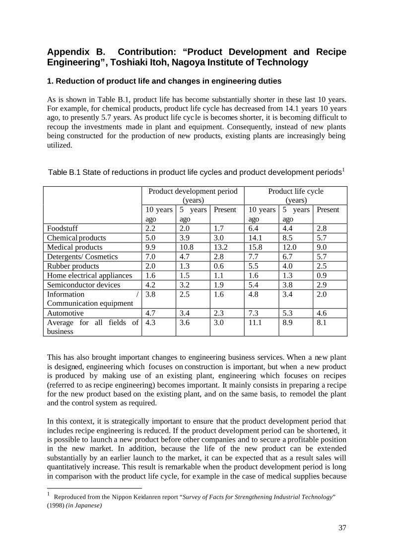
Appendix B. Contribution: “Product Development and Recipe Engineering”, Toshiaki Itoh, Nagoya Institute of Technology 1. Reduction of product life and changes in engineering duties As is shown in Table B.1, product life has become substantially shorter in these last 10 years. For example, for chemical products, product life cycle has decreased from 14.1 years 10 years ago, to presently 5.7 years. As product life cyc le is becomes shorter, it is becoming difficult to recoup the investments made in plant and equipment. Consequently, instead of new plants being constructed for the production of new products, existing plants are increasingly being utilized. Table B.1 State of reductions in product life cycles and product development periods1
Product development period
(years) Product life cycle
(years)
10 years ago
5 years ago
Present 10 years ago
5 years ago
Present
Foodstuff 2.2 2.0 1.7 6.4 4.4 2.8 Chemical products 5.0 3.9 3.0 14.1 8.5 5.7 Medical products 9.9 10.8 13.2 15.8 12.0 9.0 Detergents/ Cosmetics 7.0 4.7 2.8 7.7 6.7 5.7 Rubber products 2.0 1.3 0.6 5.5 4.0 2.5 Home electrical appliances 1.6 1.5 1.1 1.6 1.3 0.9 Semiconductor devices 4.2 3.2 1.9 5.4 3.8 2.9 Information / Communication equipment
3.8 2.5 1.6 4.8 3.4 2.0
Automotive 4.7 3.4 2.3 7.3 5.3 4.6 Average for all fields of business
4.3 3.6 3.0 11.1 8.9 8.1
This has also brought important changes to engineering business services. When a new plant is designed, engineering which focuses on construction is important, but when a new product is produced by making use of an existing plant, engineering which focuses on recipes (referred to as recipe engineering) becomes important. It mainly consists in preparing a recipe for the new product based on the existing plant, and on the same basis, to remodel the plant and the control system as required. In this context, it is strategically important to ensure that the product development period that includes recipe engineering is reduced. If the product development period can be shortened, it is possible to launch a new product before other companies and to secure a profitable position in the new market. In addition, because the life of the new product can be extended substantially by an earlier launch to the market, it can be expected that as a result sales will quantitatively increase. This result is remarkable when the product development period is long in comparison with the product life cycle, for example in the case of medical supplies because 1 Reproduced from the Nippon Keidanren report “Survey of Facts for Strengthening Industrial Technology” (1998) (in Japanese)

38
product life cycle is in average 9 years, if the 13.2 years period it takes on average for product development were reduced by 10%, it could be expected that the product life cycle would be extended by 15%, or 10.3 years: an increase in sales of 1.3 years. 2. Recipe engineering NAMUR2, a group of instrumentation and control engineers from chemical companies located along the River Rhine, presented in 1992 “Requirements to be met by systems for recipe-based operations”. Among these requirements, NAMUR arranges the recipes which decide on the relationship between the R&D process and the control system as in Fig. B.13. Within this, three important concepts are included.
Fig. B.1 Recipe-based operation model The first is to express the process of developing the product, with 3 types of recipes: The General Recipe, the Basic Recipe and the Control Recipe4. The General Recipe is prepared at the research and development stage. Information concerning the plant is not included in the General Recipe. The Basic Recipe which is prepared at the engineering stage is a production recipe that designates the preconditions for production in a particular plant. As for the Control Recipe which consists in a production recipe which is executed with the batch process control system, it details the Basic Recipe, and reflects the actual state of the plant (e.g. in the process of equipment maintenance etc.) 2 NAMUR was founded at Leverkusen on November 3, 1949, as the body to represent the interests of the users of measurement and control technology in the chemical industry by such renowned experts in the field as Dr. Sturm (Bayer), Dr. Hengstenberg (BASF) and Dr. Winkler (Hüls). (http://www.namur.de/index.html) 3 NAMUR-Empfehlung: Anforderungen an Systeme zur Rezeptfahrweise, NAMUR AK 2.3 Funktionen der Betriebs-und Produktionsleitebene (1992) 4 In S88 the Site Recipe is defined between the General Recipe and the Basic Recipe
Informat ion Function
RESEARCH ENGINEERING PRODUCTION
General Recipe
Adapt General Recipe in Operation & Scale
Basic Recipe
BO and BF Library
Relation BF-U-TF
Production Schedule
Create Control Recipe
Control Recipe
Execute Control Recipe
Actuating Variables
Create Production
Report
Batch Report
Create Batch Report
Actual State
Design BO and BF
Line Description
Production Management Level
Production Report
Operation Management Level
Process Control Level
Field Level
BO: Basic Operation BF: Basic Function U: Unit TF: Technical Function

39
By making use of these 3 types of recipes NAMUR has modeled the product/commodity development process completed by R&D ? engineering ? production. The second concept is that the possibility of automatically synthesizing the Basic Recipe and the Control Recipe has been demonstrated.
In Fig. B.1, the Basic Recipe is meant to conform to the function written in the General Recipe, corresponding to the production procedure and the production equipment. Specifically, if the production procedure written in the General Recipe (in Fig. B.1 BO: Basic Operation) and the function corresponding to production equipment (in Fig. B.1 BF: Basic Function) are assembled and replaced in the operational procedure of production equipment, it is possible to make the Basic Recipe by scaling-up or scaling-down the Formula with the production equipment statistics written in the General Recipe. In addition it is possible to make the Control Recipe as follows. First, from the production volume completed with a production schedule, the Formula5 which determines the required quantity of raw materials, additives, etc., is completed. Then, the use of equipment modules is determined by considering the state of each equipment module of production equipments (e.g. in the process of routine inspection, or in the process of breaking down, etc.). Lastly, the Control Recipe is completed by detailing the production equipments’ operational procedure written in the Basic Recipe to the level of operation of each equipment module (in Fig. B.1 TF: Technical Function). When the preparation of a recipe, as shown in Fig. B.1, can be done either automatically or in a simpler way with computer aided techniques, the Control Recipe can be completed in a short period with the General Recipe obtained at the research and development stage, and a substantial reduction in the product development period can be expected. In addition, because the management of recipe modifications is also systematized, not only can business be rationalized within a company, but trouble with respect to quality and safety and accidents can be prevented, which is likely to help gain greater trust from the customers. The third concept is to organize the philosophy of batch processing production control. In the production column of Fig.B.1, production control is done by constructing four feedback loops. At the field level, feedback loops such as normal temperature regulation, or the kind of feedback loop that relates to the valve opening and closing command and it’s verification signals with limit switches, are constructed (feedback loop # 1). At the Process Control level, while checking the conditions for transition of the operation, phase or chemical step, the execution of the recipe is managed (feedback loop # 2). This function and those that adjust the function of the field level are functions of the general batch process control system.
5 In JIS C 1807:2002 Batch Control-Part 1: Models and Terminology, “Formula” has been translated in Japanese as “recipe parameter”. It points to the names and quantities of raw materials, energy, and of resources such as energy and man-power that are necessary for production (process inputs), to the production condition such as temperature, pressure and time (process variables) and to the names and quantities of the substances, energy, and by-products etc., formed by the execution of the recipe (process outputs).

40
At the Operation Management level, the batch report is checked against the recipe. This consists in verifying whether or not production is done according to the recipe (feedback loop # 3). The results of the verification are examined, for example, if the heating time took longer than in the recipe and fouling of the heating surface is assumed, washing will be taken into consideration. In addition if a deviation in product quality can be noted, an adjustment is done to the Formula. In this way, the recipe is the core of production control. Though this is not written on the figure, at the Production Management level the production report is compared to the production schedule (feedback loop # 4). If production was not done as planned, it means that the production schedule should be modified. In short, with recipe engineering, the principal theme for systematic approach for recipe engineering is to assure the systematization of the “R&D ? engineering ? production” product development process, and the systematization of production management and control, with the recipe as the core element. 3. Technological challenges and state of R&D in relation to recipe engineering The technology and the tools required for recipe engineering have not yet been established and are still in development. The main technological challenges and the state of research and development are mentioned below.
Recipe procedure design Domestically, considerable research is underway to enable the procedure of the recipe design process to classify
1. Synthesis of the production route and the determination of the use of units6 2. Synthesis of the transportation procedure7 3. Synthesis of the operational procedure within each unit8 4. Exceptional handling of the operational procedure9
In addition, a support system for these features is also in development 10. Formula conversion rule In order to produce a product of the same quality with differing unit scales and unit
6 Hoshi, Yamashita, Suzuki: Operating Procedure Formation Algorithm Based on the Graph Expression of Batch Processes, SICE System Information Section Scientific Seminar Dissertations Collection, (2001) (in Japanese) 7 Hamaguchi, Hashimoto, Itoh, Yoneda, Tokari: Autonomous Decentralized Control System for Batch Process, SICE Control Section Conference Data, 495-498 (2002) (in Japanese) 8 Hashizume, Yamashita, Onogi: Synthesis and of Operating Procedure for Batch Control with Hierarchical Petri Nets, SICE System Information Section Scientific Seminar Dissertation, (2001) (in Japanese) 9 Japan Society for the Promotion of Science PSE143 committee WS20 report, Batch Process Modelling for Operation and Management, (1999) (in Japanese) 10 Aoyama, Gabbar, Naka: Information Model for Customer Oriented Production, Automatic Generation of Control Recipe, Control Layer, Customer Oriented Production System Workshop Research Report, 3-17, (2003) (in Japanese)

41
specifications, it is necessary to search for the conversion rule of the operating conditions. If a conversion rule can be established, Formula for scale-up or scale-down becomes possible without experimentation.
The control rules adapted to the recipe If the parameters of the control algorithm can be modified for varying production volumes and production conditions in every Control Recipe, it can be expected that control performance will be improved. That is because within model predictive control a dynamic model of the plant is built- in, it is possible to have production volume and production conditions be reflected by the parameters of the control algorithm11.
Batch process scheduling A recipe is something which deals with a single batch. Since within a single process, several batches may be in progress independently, the coordination between batches must be taken into consideration. For instance, synchronization is important for unit to unit transfers. As for common resources such as measuring tanks and effluent drainage units, allocation control must comply with the requirements of the batch. Likewise, operations such as washing units which do not take place at each batch but have a major impact on product quality must be inserted into the schedule. Since this type of batch process scheduling has a major effect on plant efficiency and on the preservation of environment, safety, and quality, considerable research has been undertaken domestically12. 4. Industrial limitations that have been overcome with recipe engineering As is shown in Fig. B.2, in order to develop a new product, the cooperation of various enterprises and industries is necessary. In the same way as it is important to develop a management system for which the supply chain crosses over (3) in the Fig. into the framework of enterprise, it is important for recipe engineering (2) in the Fig. to cross over and to be developed within the framework of enterprise and industry. In particular, for systematizing the strength of “suri awase 13” (literally fitting by rubbing), i.e. adaptive integration, which is the strength of the Japanese industrial technology, recipe engineering will probably perform an important role. Recipe engineering is not something that should be limited to batch processes, but should also be applied to discrete processes and continuous processes. When it transfers to the framework of industry and enterprise, we expect that various people will be interested in recipe engineering.
11 Eguchi, Noguchi, Ozaki, Itoh: Recent Technological Trends and Future Perspectives for Batch Process, M&E April, (2003) (in Japanese) 12 Shinji Hasebe: Production Planning and Scheduling ? What is the Real World? ? Proc. of the Int. Symp. on Design, Operation and Control of Next Generation Chemical Plants (PSEAsia2000), pp.617-622 (2000) 13 Functional Industrial Chemistry Workshop: Challenges to the Value Oriented Industry Brought by the Creation of New Enterprises & Industrial Culture (2002) (in Japanese)

42
Fig. B.2 Cross-industry Recipe Engineering
Functional design
Element engineering development
Basic design
Functional creation/design
Selection of chemistry
Synthesis route design
Trial manufacture
Evaluation
Product design
Sample synthesis
Evaluation
Recipe design
Line design
Industrial production
Process design
Industrial production
(1)
(2)
(3)
Ma
rk
et
Product sale
Sample sale
Market research
Components & devices Functional material

43
References • Japanese Standards Association publication, JIS C 1807:2002 Batch control – Part 1:
Models and Terminology (2002) • Japan Society for the Promotion of Science PSE143 committee WS17 report, Systematic
Approach to Design, Operation, and Management, (1999) (in Japanese) • Japan Society for the Promotion of Science PSE143 committee WS20 report, Batch
Process Modeling for Operation and Management, (1999) (in Japanese) • Jim Parshall, Larry Lamb: Applying S88 Batch Control from a User's Perspective, ISA
(1999) • ANSI/ISA 88.00.03-2003: Batch Control – Part 3: General and Site Recipe Models and
Representation (2003)


Please consent to the following conditions when you make use of this document:
- The copyright of this document is held by the Japan Association for the Promotion of
Science Process Systems Engineering 143rd committee’s standing SIG, JBF. - Its redistribution is permitted. - Without altering its contents, it is permitted to quote this text as a reference (JBF:
Introduction to S88, March 2007). - Please refrain from using it other than for non-profit purposes.

Japan Society for the Promotion of Science Process Systems Engineering, 143rd committee
standing SIG
JBF
http://jbf.pse143.org/