Embed Size (px)
Citation preview
Introduction to Radar Systemand Component TestsWhite Paper
This White Paper provides a generaloverview of different military andcommercial radar systems. It also coverssome typical measurements on suchsystems and their components.
Appli
catio
nNo
te
Rolan
dMini
hold
/Diet
erBu
es08
_201
2-1M
A207
_0e

Contents
1MA207_0e Rohde & Schwarz Introduction to Radar System and Component Tests 2
Table of Contents
1 Abstract .................................................................................. 3
2 Overview of Typical Radar Applications and Common RadarTypes....................................................................................... 4
2.1 Typical radar applications...........................................................................4
2.2 Radar Frequencies, - Bands, Wavelength and Applications ...................5
3 Radar Equation....................................................................... 6
4 Common Radar Types ........................................................... 94.1 CW (Doppler) and FMCW (Doppler (Speed)/Range) Radar) .....................9
4.2 Simple Pulse (Range) and Pulse Doppler (Speed/Range) Radar ..........11
4.3 Pulse Doppler radar ...................................................................................12
4.4 Pulse Compression Radar (FM Chirp and Phase Coded) ......................13
4.5 Frequency-Agile Radar (FAR) - Suppression of Jamming and ImprovedClutter Rejection.........................................................................................14
4.6 Stepped-Frequency Radar (Imaging Application)...................................14
4.7 Moving-Target Identification (MTI) Radar ................................................15
4.8 Monopulse Radar (Phase or Amplitude Comparison) / (Range and AngleMeasurement) .............................................................................................16
4.9 Phased-Array Radar, Digital Beamforming .............................................17
4.10 Synthetic-Aperture Radar (SAR)...............................................................20
4.11 Bistatic, Multistatic Radar .........................................................................21
4.12 Passive Radar.............................................................................................21
4.13 Multimode Radar ........................................................................................22
4.14 The Future of Radar Developments..........................................................24
5 Common Radar Abbreviations............................................ 25
6 Literature............................................................................... 28
7 Additional Information......................................................... 28

1MA207_0e Rohde & Schwarz Introduction to Radar System and Component Tests 3
1 AbstractIt was German engineer Christian Huelsmeyer who first used the radar principle tobuild a simple ship detection device intended to help avoid collisions in fog(Reichspatent Nr. 165546).
First widely used radar technology was developed for military purpose during WorldWar II. Today, more than half a century later, there is a much wider radar applicationarea beyond the military one. Radar is needed for weather forecast, airport trafficcontrol and automotive applications such as car distance surveillance and pedestriandetection. Additionally radar technology today is affordable on a mass production basisdue to highly integrated signal processing components which make it possible to detecteven low power signals in applications where at former times much more RF energywas needed. Low power radar components automatically mean savings in costs andsize. In addition there are a lot of CAD tools available for the development of suchsystems and to deal with higher frequencies up to 110 GHz and beyond.
R&S created two complementary papers, application note 1MA127 and white paper1MA207 regarding current radar technology in order to demonstrate its contribution totest and measurement of radar systems and components. The white paper gives anoverview on radar Systems and important measurements on them. The correspondingapplication note 1MA127 goes into details in explaining radar test technology alongwith the specific products needed to perform the tests. Both documents, 1MA127 and1MA207 are addressing students who want to become familiar with radar issues aswell as radar professionals who want to solve certain test and measurement tasks.

1MA207_0e Rohde & Schwarz Introduction to Radar System and Component Tests 4
2 Overview of Typical Radar Applicationsand Common Radar Types
2.1 Typical radar applications
Typical radar applications are listed here to give an idea of the huge importance ofradar in our world.
SurveillanceMilitary and civil air traffic control, ground-based, airborne, surface coastal, satellite-based
Searching and trackingMilitary target searching and tracking
Fire controlProvides information (mainly target azimuth, elevation, range and velocity) to a fire-control system
NavigationSatellite, air, maritime, terrestrial navigation
AutomotiveCollision warning, adaptive cruise control (ACC), collision avoidance
Level measurementsFor monitoring liquids, distances, etc.
Proximity fusesMilitary use: Guided weapon systems require a proximity fuse to trigger the explosivewarhead
AltimeterAircraft or spacecraft altimeters for civil and military use
Terrain avoidanceAirborne military use
Secondary radarTransponder in target responds with coded reply signal
WeatherStorm avoidance, wind shear warning, weather mapping
SpaceMilitary earth surveillance, ground mapping, and exploration of space environment
SecurityHidden weapon detection, military earth surveillance
1MA207_0e Rohde & Schwarz Introduction to Radar System and Component Tests 5
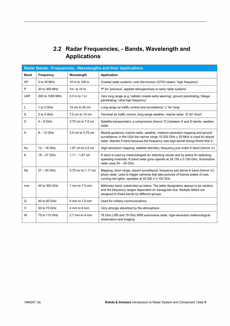
2.2 Radar Frequencies, - Bands, Wavelength andApplications
Radar Bands, -Frequencies, -Wavelengths and their ApplicationsBand Frequency Wavelength Application
HF 3 to 30 MHz 10 m to 100 m Coastal radar systems, over-the-horizon (OTH) radars; 'high frequency'
P 30 to 300 MHz 1m to 10 m 'P' for 'previous', applied retrospectively to early radar systems
UHF 300 to 1000 MHz 0.3 m to 1 m Very long range (e.g. ballistic missile early warning), ground penetrating, foliagepenetrating; 'ultra high frequency'
L 1 to 2 GHz 15 cm to 30 cm Long-range air traffic control and surveillance; 'L' for 'long'
S 2 to 4 GHz 7.5 cm to 15 cm Terminal air traffic control, long-range weather, marine radar; 'S' for 'short'
C 4 – 8 GHz 3.75 cm to 7.5 cm Satellite transponders; a compromise (hence 'C') between X and S bands; weatherradar
X 8 – 12 GHz 2.5 cm to 3.75 cm Missile guidance, marine radar, weather, medium-resolution mapping and groundsurveillance; in the USA the narrow range 10.525 GHz ± 25 MHz is used for airportradar. Named X band because the frequency was kept secret during World War 2.
Ku 12 – 18 GHz 1.67 cm to 2.5 cm High-resolution mapping, satellite altimetry; frequency just under K band (hence 'u')
K 18 – 27 GHz 1.11 – 1.67 cm K band is used by meteorologists for detecting clouds and by police for detectingspeeding motorists. K band radar guns operate at 24.150 ± 0.100 GHz. Automotiveradar uses 24 – 26 GHz.
Ka 27 – 40 GHz 0.75 cm to 1.11 cm Mapping, short range, airport surveillance; frequency just above K band (hence 'a');photo radar, used to trigger cameras that take pictures of license plates of carsrunning red lights, operates at 34.300 ± 0.100 GHz
mm 40 to 300 GHz 1 mm to 7.5 mm Millimeter band, subdivided as below. The letter designators appear to be random,and the frequency ranges dependent on waveguide size. Multiple letters areassigned to these bands by different groups.
Q 40 to 60 GHz 5 mm to 7.5 mm Used for military communications
V 50 to 75 GHz 4 mm to 6 mm Very strongly absorbed by the atmosphere
W 75 to 110 GHz 2.7 mm to 4 mm 76 GHz LRR and 79 GHz SRR automotive radar, high-resolution meteorologicalobservation and imaging

1MA207_0e Rohde & Schwarz Introduction to Radar System and Component Tests 6
3 Radar EquationThe acronym RADAR stands for RAdio Detection And Ranging. Figure 1 shows thebasic principle.
Figure 1: Basic principle of Radar and its parameters
An electromagnetic wave of power Pt is transmitted to a flying object, for example to aplane and is partly reflected back to the antenna with the receiving power Pr. From thetime delay between the transmitted and received signal the distance to the plane canbe calculated. Additional information can be gained from the frequency shift of thereceived signal, which is proportional to the speed of the plane.
Receiving a signal of sufficient power by an adequate power to noise ratio is thebiggest challenge of radar systems. The so called “Radar Equation” gives hints on thepower relations within the system as indicated in Figure 1.The Radar Equation delivers the received power Pr as result. According to the RadarEquation following independent parameters determine the received power Pr :
43
22
*)4(*R
GPP tr
(Formula 1)
● Pt: The power transmitted by the antenna, dimension is dBm. Numeric examples :63 dBm for real world Radar applications, 13 dBm for laboratory tests
● G: Gain of the transmitting antenna, dimension in dBi. The parameter determineshow much the radiation beam of the antenna is focused toward the direction of thetarget. Numeric examples are 12 dBi for a BiQuad antenna and 70 dBi for a highlyfocusing parabolic antenna.

1MA207_0e Rohde & Schwarz Introduction to Radar System and Component Tests 7
● λ: The wavelength of the transmitted signal, dimension in meter. The wavelengthcan be directly calculated from the frequency. Numeric examples: 0.03 m for a 10GHz signal and 0.12 m for a 2.54 GHz signal
● б: Radar cross section, RCS, is a virtual area representing the intensity of thereflection. Not all of the radiated power is reflected back to transmitting antenna, asindicated by the small waves close to the plane in Figure 1. The “Sigma” ( ) of theobjects determines the virtual area of the reflecting object (plane) from which all ofthe incoming radiation energy is reflected back to the antenna. The dimension issquare meter, “m2” in short. Practical examples are 12 m2 for a commercial plane,1 m2 for a person or 0.01 m2 for a bird. Refer to [18], page 6665 for furtherexamples.
● R: Distance between the transmitting antenna and the reflecting object. Dimensionin m. Numeric examples are 8000 m for real world applications or 5 m forlaboratory conditions. It has to be stressed that this parameter reduces the result,i.e. the received signal by the power of 4, with the effect that far distant objects areproviding only a small amount of received power.
ExampleParameter Abbreviation Value, Example 1 Value Example 2 Unit
Transmitted power Pt 63 13 dBm
Gain of transmit antenna G 28 12 dBi
Wavelength (frequency) (f) 0.03 (10*109) 0.12 (2.5*109) m(Hz)
Radar cross section 12 0,3 m2
Distance R 8114 5 m
Received power, linear Pr 1 17.4*103 pW
Received power, logarithmic Prlog -90 -48 dBm
Table 1: Parameters of Radar Equitation and two examples
● Example 1 shows a a real world example, derived from [Pozar], example 2 showsa radar application which can be realized under laboratory conditions for examplein an anechoic chamber.
●● Example 1 read in clear text : A radar transmitting antenna with gain of 28 dBi is
transmitting an electromagnetic wave at 10 GHz with a power of 63 dBm to a planein a distance of about 8000 m. The plane has a radar cross section of 12 m2 . Bymeans of the Radar Equation the received power back at the antenna is calculatedto -90 dBm.
● Example 2 read in clear text: In a radar test laboratory implemented in ananechoic chamber a test transmitter provides 13 dBm to a matched antenna of12 dBi with a frequency of 2.5 GHz. The reflecting object with a cross section of0.3 m2 is located in 5 m distance from the transmitting antenna. According to theRadar Equation the test receiver is going to receive a reflected signal of -48 dBm.

1MA207_0e Rohde & Schwarz Introduction to Radar System and Component Tests 8
● When comparing example 1 to example 2 we can conclude that despite muchbigger transmitting power, better transmit antenna gain and bigger radar crosssection in example 1 the received reflected power of example 1 is almost 50 dBlower than the received signal of example 2. The reason is the smaller wavelengthlambda which affects the result by a power of 2 and especially the bigger distanceR of example 1 which affects the result by a power of 4. Small wavelengths, i.e.high frequencies are aimed for in most radar systems, especially in antennaarrays, because of the resulting small antenna size. It is obvious also, that in radartechnology one has to deal with very small receiving power especially for fardistant objects.

1MA207_0e Rohde & Schwarz Introduction to Radar System and Component Tests 9
4 Common Radar TypesThis section lists the most common types of radar systems with brief explanations of how theywork.
4.1 CW (Doppler) and FMCW (Doppler (Speed)/Range)Radar)
A continuous wave (CW) radar system with a constant frequency can be used to measure speed.However, it does not provide any range (distance) information. A signal at a certain frequency istransmitted via an antenna. It is then reflected by the target (e.g. a car) with a certain Dopplerfrequency shift. This means that the signal's reflection is received on a slightly differentfrequency. By comparing the transmitted frequency with the received frequency, we candetermine the speed (but not the range). Here, a typical application is radar for monitoring traffic.Radar motion sensors are based on the same principle, but they must also be capable ofdetecting slow changes in the received field strength due to variable interference conditions thatmay exist.Radar speed traps operated by the police use this same technology. Camera systems take apicture if a certain speed is exceeded at a specified distance from the target.
Figure 2: Mobile traffic monitoring radar MultaRadar CD - Mobile speed radar for speed enforcement fromJenoptic

1MA207_0e Rohde & Schwarz Introduction to Radar System and Component Tests 10
There are also military applications:CW radars are also used for target illumination. This is a straightforward application: The radarbeam is kept on target by linking it to a target tracking radar. The reflection from the target is thenused by an antiaircraft missile to home in on the target.CW radars are somewhat hard to detect. Accordingly, they are classified as low-probability-of-intercept radars.CW radars lend themselves well to detecting low-flying aircraft that attempt to overcome anenemy's air defense by "hugging the ground". Pulsed radar has difficulties in discriminatingbetween ground clutter and low-flying aircraft. CW radar can close this gap because it is blind toslow-moving ground clutter and can pinpoint the direction where something is going on. Thisinformation is relayed to co-located pulse radar for further analysis and action. [7]
FMCW radarThe disadvantage of CW radar systems is that they cannot measure range due to the lack of atiming reference. However, it is possible to generate a timing reference for measuring the rangeof stationary objects using what is known as "frequency-modulated continuous wave" (FMCW)radar. This method involves transmitting a signal whose frequency changes periodically. Whenan echo signal is received, it will have a delay offset like in pulse radar. The range can bedetermined by comparing the frequency. It is possible to transmit complicated frequency patterns(like in noise radar) with the periodic repetition occurring at most at a time in which no ambiguousechoes are expected. However, in the simplest case basic ramp or triangular modulation is used,which of course will only have a relatively small unambiguous measurement range.
Figure 3: Basic principle of FMCW radar. The target’s velocity is calculated based on the measured delay tbetween the transmit signal and the received signal, whereas the frequency offset f gives the range
This type of range measurement is used, for example, in aircraft to measure altitude (radioaltimeter) or in ground tracking radar to ensure a constant altitude above ground. One benefitcompared to pulse radar is that measurement results are provided continuously (as opposed tothe timing grid of the pulse repetition frequency).FMCW radar is also commonly used commercially for measuring distances in other ways, e.g.level indicators.Automotive radar is in most cases FMCW radar too.

1MA207_0e Rohde & Schwarz Introduction to Radar System and Component Tests 11
4.2 Simple Pulse (Range) and Pulse Doppler (Speed/Range)Radar
Figure 4: Basic principle of a simple pulse radar system
A simple pulse radar system only provides range (plus direction) information for a target basedon the timing difference between the transmitted and received pulse. It is not possible todetermine the speed. The pulse width determines the range resolution.
Figure 5: Direction information with azimuth angle determination in a radar system with a rotary antenna
The direction information (azimuth angle φ) is determined from the time instant of the receivepulse with reference to the instantaneous radiation direction of the rotating antenna.The important measurements on (non-coherent) radar equipment of this sort are the rangeaccuracy and resolution, AGC settling time for the receiver, peak power, frequency stability,phase noise of the LO and all of the pulse parameters.The AGC circuit of the receiver protects the radar from overload conditions due to nearbycollocated radars or jamming countermeasures. The attack and decay time of the AGC circuitcan be varied based on the operational mode of the radar. Since the roundtrip of a radar signalstravels approximately 150 meters per microsecond, it is important to measure the response of theAGC for both amplitude and phase response when subject to different overload signal conditions.The measured response time will dictate the minimum detection range of the radar.
1MA207_0e Rohde & Schwarz Introduction to Radar System and Component Tests 12
4.3 Pulse Doppler radar
A pulse Doppler radar also provides radial speed information about the target in addition to rangeinformation (and direction information). In case of coherent operation of the radar transmitter andreceiver, speed information can be derived from the pulse-to-pulse phase variations. I/Qdemodulators are normally used. The latest pulse Doppler radar systems normally use differentpulse repetition frequencies (PRF) ranging from several hundred Hz up to 500 kHz in order toclarify any possible range and Doppler ambiguities.More advanced pulse Doppler radar systems also " use "staggered PRF, i.e. the PRF changeson an ongoing basis to get rid of range ambiguity and reduce clutter as well.Important criteria for achieving good performance in pulse Doppler radar systems include verylow phase noise in the LO, low receiver noise and low I/Q gain phase mismatch (to avoid "falsetarget indication") in addition to the measurement parameters listed above.When measuring the pulse-to-pulse performance of a radar transmitter, it is important tounderstand the variables that can impact the uncertainty of the measurement system for accurateDoppler measurements:
● Signal-to-noise ratio of the signal - the better the signal to noise ratio of the signal, the lowerthe uncertainty due to noise contribution.
● Bandwidth of the signal - the bandwidth of the IF acquisition system must be sufficient toaccurately represent the risetime of the pulsed signal, however too much bandwidth canresult in added noise contribution uncertainty.
● Reference (or timebase) clock stability.
● Jitter or uncertainty due to the measurement point of the rising edge of the signal – risingedge interpolation or signals that have changing edges impact this uncertainty.
● Overshoot and preshoot of the rising and falling edges – any ringing on the rising and fallingedges can impact the measurement points adversely on a pulse to pulse basis. It is importantthat the measurement point, or the average set of measurement points, are sufficiently faraway in time from the leading and falling edges of a pulse. Applying a Gaussien filter tosmooth the impact of the rising and falling edges can reduce this phenomena and is oftenimplemented in the Doppler measurement system of a radar receiver.
● Time between measured signals – due to the PRI of the measured signal, the close-in phasenoise of the measurement system needs to be considered due to the integration time atlower offset frequencies.
● The same variables can also contribute to the uncertainty in the signal generator whentesting the receiver circuit and Doppler measurement accuracy.
1MA207_0e Rohde & Schwarz Introduction to Radar System and Component Tests 13
4.4 Pulse Compression Radar (FM Chirp and Phase Coded)
Classic pulse and pulse Doppler radar transmits extremely short pulses. Increasing the pulsepower allows the radar system to achieve greater range results. Decreasing the duration of thetransmit pulses also decreases the pulse volume and provides better range resolution for theradar system, i.e. closely spaced targets can be distinguished with smaller distances betweenthem.Pulse compression combines the power-related benefits of very long transmit pulses (goodrange) with the benefits of very short transmit pulses (high distance resolution). Lower peakpower can then be used.By modulating the transmit pulses, a timing reference is produced within the transmit pulse,similar to frequency-modulated continuous wave (FMCW) radar systems. Several differentmodulation techniques can be used. The most common are:
● Linear frequency modulation (FM chirp)● Non-linear frequency modulation● Encoded pulse phase modulation (e.g. Barker code)● Polyphase modulation and time-frequency coded modulation
Although pulse compression technique has various benefits such as low pulse power with goodrange and distance resolution, there is a significant disadvantage: The minimum measurementrange is degraded depending on the pulse length, since the radar receiver is blocked during thetransmit pulse. As this is a major disadvantage for radar systems used for air traffic control, theytypically use both techniques: Between the frequency-modulated pulses for the larger range,small (very short) pulses are transmitted which only have to cover the nearby area and do notrequire very high pulse power.● Linear FM is most common in older radar systems. An example is the air-defense radar RRP-
117 [4][4].● Non-linear FM (NLFM) is becoming more practical use because of its various benefits such
as inherently low range sidelobes which yields an advantage in SNR compared to Linear FM.[16]
● Encoded pulse phase modulation is very common, particularly Barker codes with lengths of11 and 13 [15].
● In advanced military radar systems, polyphase pulse compression is also used increasinglywith special codes [14].
Pulse compression radar signal require baseband IQ collection of the signal covering the BW ofthe pulse risetime, wideband analog FM demodulation or vector demodulation and new displaysof the information for analysis (amplitude, frequency, and phase vs. time), and digitaldemodulation/EVM measurement for BPSK/QPSK modulations.

1MA207_0e Rohde & Schwarz Introduction to Radar System and Component Tests 14
4.5 Frequency-Agile Radar (FAR) - Suppression of Jammingand Improved Clutter Rejection
Frequency hopping is an effective technique for a radar system to circumvent jamming andelectronic counter-countermeasures (ECCM). It is typically used in military radar applications.Clutter rejection is also possible using FAR. Sub-microsecond switching times and bandwidthsranging from several hundred MHz in the X band to over 2 GHz at 95 GHz are typical.Other measurement parameters that are relevant with FAR include the frequencyswitching/settling time, hop sequence, switching spurious and broadband amplitude and phasestability. This type of radar should consider the test of the radar not under static conditions, butthe hopping conditions across the BW of interest. Oscilloscopes with FFT analysis often need tobe employed to assess hopping performance and anomalies due to hopping sequences.
4.6 Stepped-Frequency Radar (Imaging Application)
Stepped-frequency radar systems are used in imaging applications. With typical bandwidthsranging from several hundred MHz to 2 GHz, resolutions of <10 cm can be achieved.
Figure 6: Timing diagram for stepped-frequency radar
The frequency is increased by a fixed value from pulse to pulse. Typical bursts contain 128pulses. The benefit of a stepped-frequency radar system is that one can obtain wide bandwidthand thus good resolution without needing a large FFT capture bandwidth [17].Due to the wide RF bandwidth of the transmitter and receiver, these subsystems must exhibitexcellent stability in order to obtain the desired high resolution. Impacted stepped frequencyradar is reduced cost of testing each pulse, but added cost of pulse to pulse coherent analysis(magnitude and phase stability is most important). As was the case with frequency agile radar,the settling time of the local oscillator is also an important measurement parameter.
1MA207_0e Rohde & Schwarz Introduction to Radar System and Component Tests 15
4.7 Moving-Target Identification (MTI) Radar
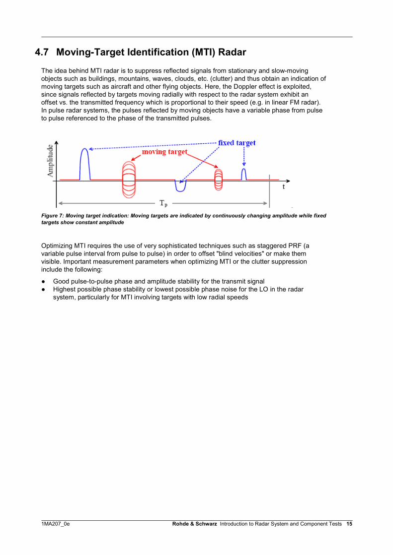
The idea behind MTI radar is to suppress reflected signals from stationary and slow-movingobjects such as buildings, mountains, waves, clouds, etc. (clutter) and thus obtain an indication ofmoving targets such as aircraft and other flying objects. Here, the Doppler effect is exploited,since signals reflected by targets moving radially with respect to the radar system exhibit anoffset vs. the transmitted frequency which is proportional to their speed (e.g. in linear FM radar).In pulse radar systems, the pulses reflected by moving objects have a variable phase from pulseto pulse referenced to the phase of the transmitted pulses.
Figure 7: Moving target indication: Moving targets are indicated by continuously changing amplitude while fixedtargets show constant amplitude
Optimizing MTI requires the use of very sophisticated techniques such as staggered PRF (avariable pulse interval from pulse to pulse) in order to offset "blind velocities" or make themvisible. Important measurement parameters when optimizing MTI or the clutter suppressioninclude the following:
● Good pulse-to-pulse phase and amplitude stability for the transmit signal● Highest possible phase stability or lowest possible phase noise for the LO in the radar
system, particularly for MTI involving targets with low radial speeds
1MA207_0e Rohde & Schwarz Introduction to Radar System and Component Tests 16
4.8 Monopulse Radar (Phase or Amplitude Comparison) /(Range and Angle Measurement)
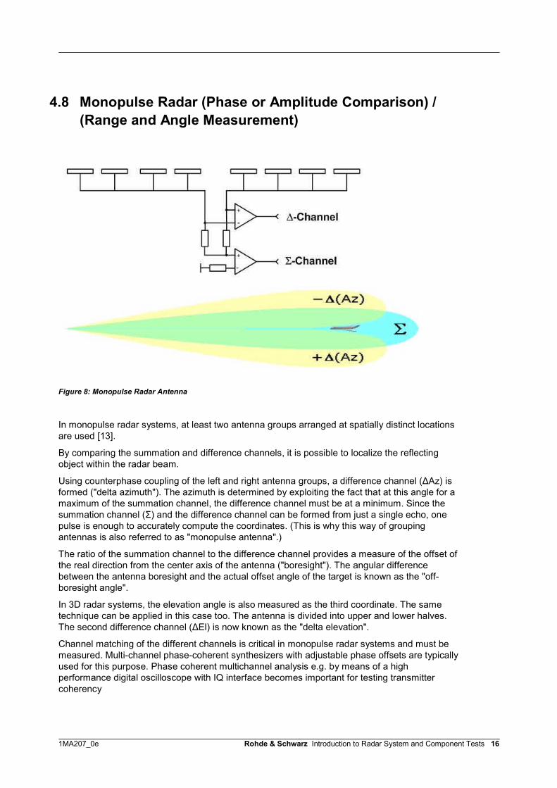
Figure 8: Monopulse Radar Antenna
In monopulse radar systems, at least two antenna groups arranged at spatially distinct locationsare used [13].
By comparing the summation and difference channels, it is possible to localize the reflectingobject within the radar beam.
Using counterphase coupling of the left and right antenna groups, a difference channel (ΔAz) isformed ("delta azimuth"). The azimuth is determined by exploiting the fact that at this angle for amaximum of the summation channel, the difference channel must be at a minimum. Since thesummation channel (Σ) and the difference channel can be formed from just a single echo, onepulse is enough to accurately compute the coordinates. (This is why this way of groupingantennas is also referred to as "monopulse antenna".)
The ratio of the summation channel to the difference channel provides a measure of the offset ofthe real direction from the center axis of the antenna ("boresight"). The angular differencebetween the antenna boresight and the actual offset angle of the target is known as the "off-boresight angle".
In 3D radar systems, the elevation angle is also measured as the third coordinate. The sametechnique can be applied in this case too. The antenna is divided into upper and lower halves.The second difference channel (ΔEl) is now known as the "delta elevation".
Channel matching of the different channels is critical in monopulse radar systems and must bemeasured. Multi-channel phase-coherent synthesizers with adjustable phase offsets are typicallyused for this purpose. Phase coherent multichannel analysis e.g. by means of a highperformance digital oscilloscope with IQ interface becomes important for testing transmittercoherency

1MA207_0e Rohde & Schwarz Introduction to Radar System and Component Tests 17
4.9 Phased-Array Radar, Digital Beamforming
Radar applications normally need some kind of dynamic beam steering, because the area of astatic electromagnetic beam is normally too small for object detection, especially within A&Dapplications. In classical radar systems mechanical devices have been used in order to move theradar beam to cover a certain area. The 360-degree rotating antenna in air surveillance systemsis the best example. Older fighter planes also are using mechanically moving radar antennas.However, mechanical systems are heavy and failure-prone which both are drawbacks forequipment being used in safety-critical applications.
Figure 9: 360-degree rotating antenna (left) of an air surveillance system and electronically steered antenna(right)
High performance Digital Signal Processing along with affordable and small, highly integratedhardware systems have made possible another technique called "digital beamforming" (DBF) orAESA (Active Electronically Scanned Array). Figure 10 shows the basic principle; the literature[2] provides detailed information.
-4
-2
0
2
4
0 1 2 3 4 5
-4
-2
0
2
4
0 1 2 3 4 5
Lmech
Antenna 1
4
Antenna 2Antenna 1 Antenna 2
4
Figure 10: Basic Principle of AESA (Active Electronically Scanned Array) or DBF (Digital Beamforming)

1MA207_0e Rohde & Schwarz Introduction to Radar System and Component Tests 18
DBF always relies on antenna arrays. Modern systems sometimes include up to 1000independent small antennas. To keep it simple, Figure 10 includes only 2 antennas. However theoperation principle is the same for all bigger systems. All subsequent discussions are related to asingle plane 2-dimensional antenna system only. The 3-dimensional real-world antenna systembehaves in a similar way.
In the example provided two sine signals of electrical energy are supplied to two isotropicantennas. An isotropic antenna is radiating equally in all directions. The two signals are of samephase and magnitude, so called coherent signals. The resulting power of the radiated sum beamis the sum of the two sine signals. Figure 10 shows the relation for the perpendicular directionwith respect to our 2-Element antenna array. The behavior in this direction of transmission isshown in the left half of Figure 10. The situation for a certain side transmission, about 45degrees, is shown in the right half. The upper part shows signal superposition, the lower halfshows the same by using vectors. Blue and green shows the electromagnetic energy transmittedfrom the two antennas. The red parts of the drawings show the two superposed antenna signals.As indicated in the lower right, the side transmission causes a phase shift (delta) of both antennasignals which causes the red sum signal to be reduced compared to the sum signal withoutphase shift. The declined sum signal can be clearly seen in the signal representation in the upperpart of Figure 10.
It can be summarized now, that the antenna array has a specific maximum propagation direction,which is 90 degrees, because of isotropic antennas supplied by two signals of same phase andmagnitude (= coherent signals). The resulting beam radiated to the side, for instance 45 degrees,is smaller due to a phase shift we are getting because of different propagation path lengths. Wecan summarize this in following table (3rd line):
Behavior of sum signalsTwo antenna supply signals 90 degrees sum signal x degrees sum signal
In phase (coherent) Maximum Less than maximum
Phase locked but not inphase(certain angle)
Less than maximum Maximum
Table 2: Behavior of sum signals dependent on phase of antenna supply signals
The way in which the antenna array sum signal is declining along with the side angle depends onthe distance between the antenna elements. It is therefore a property specific to the geometry ofthe antenna array. Additionally it depends on the wavelength, i.e. the frequency of the radarsignal, because the phase shift is related to the wavelength.
So far considered two antenna supply signals of same magnitude and phase have beenconsidered, so called coherent signals. If a small phase shift is applied now in between bothsignals, we can reverse the effects so far described, i.e. decline the 90-degree beam andincrease the 45 degree side beam to a maximum. If the phase between both signals is increaseduntil a certain value the beam moves slowly ato 45 degree. Turning the beam by a certain angleis one way of so called "beamforming". The results can now be summarized again in Table 2,lowest line.The phase shift of antenna array supply signals can be generated in different ways. The simplestway is to use supply cables of different lengths. Another method is to implement phase-shiftingelements in the appropriate antenna supply circuits. However, both methods are static and thephase shift can't be externally controlled. The Application Note 1MA127 related to this WhitePaper, describes an integrated circuit performing digitally controlled phase shifting. It is alsoshown how such phase shifters can be directly digitally controlled by test instruments, ex.network analyzers.A high performance digital scope can be suited to test the transmitted delay between up to 4channels of T/R modules if the skew between the scope channels is sufficiently low (<< 1 ns).
1MA207_0e Rohde & Schwarz Introduction to Radar System and Component Tests 19
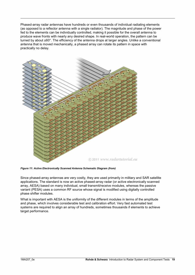
Phased-array radar antennas have hundreds or even thousands of individual radiating elements(as opposed to a reflector antenna with a single radiator). The magnitude and phase of the powerfed to the elements can be individually controlled, making it possible for the overall antenna toproduce wave fronts with nearly any desired shape. In real-world operation, the pattern can beturned by about ±60°. The efficiency of the antenna drops at larger angles. Unlike a conventionalantenna that is moved mechanically, a phased array can rotate its pattern in space withpractically no delay.
Figure 11: Active Electronically Scanned Antenna Schematic Diagram (from)
Since phased-array antennas are very costly, they are used primarily in military and SAR satelliteapplications. The standard is now an active phased-array radar (or active electronically scannedarray, AESA) based on many individual, small transmit/receive modules, whereas the passivevariant (PESA) uses a common RF source whose signal is modified using digitally controlledphase shifter modules.
What is important with AESA is the uniformity of the different modules in terms of the amplitudeand phase, which involves considerable test and calibration effort. Very fast automated testsystems are required to align an array of hundreds, sometimes thousands if elements to achievetarget performance.

1MA207_0e Rohde & Schwarz Introduction to Radar System and Component Tests 20
4.10 Synthetic-Aperture Radar (SAR)Synthetic-aperture radar (SAR), like the related real-aperture radar (RAR; see also side-lookingairborne radar), belongs to the class of mapping radar systems. Such radar systems aredeployed in aircraft or satellites to provide a two-dimensional view of a section of terrain byscanning the earth's surface using electromagnetic waves.In defense industry, inverse synthetic aperture radar imaging (ISAR) of moving objects is animportant tool for automatic target recognition.Both SAR and ISAR have the same underlying theory, the main difference is thegeometry configuration. In SAR imaging, the radar is flying in the space, and the objectis stationary, while in ISAR imaging, the object is moving and the radar is stationary. Butonly the relative movement between the object and the radar is important. So the ISARimaging problem can be found to be equivalent to the more easily understood SARimaging problem.The basic principle behind SAR involves an antenna that can be moved perpendicularly to theradiation direction. The position must be precisely known at all times. The direction of motion isnormally referred to as the "along track" or azimuth and the related cross coordinate as the "crosstrack" or range. The "footprint" is the area which the real antenna is currently covering. The"swath" is the strip of terrain which the footprint crosses due to the ongoing motion of the realantenna.SAR involves replacing the instantaneous snapshot produced by a large antenna with manysnapshots produced using a small, mobile antenna. During the course of the related movement,each object in the target area is illuminated at a different angle of view and recorded accordingly.As long as the path of the real antenna is known with sufficient accuracy, the aperture of a largeantenna can be synthesized on the basis of the magnitude and phase of the received radarechoes in order to attain a high spatial resolution in the direction in which the antenna is moving.
Figure 12: Synthetic-aperture radar (SAR). The SAR antenna beam is moved back and forth while traveling alongthe azimuth
1MA207_0e Rohde & Schwarz Introduction to Radar System and Component Tests 21
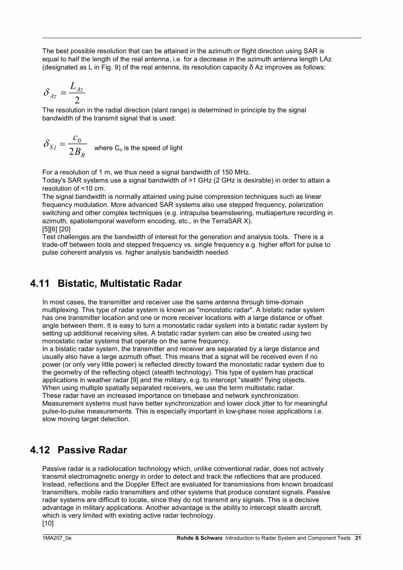
The best possible resolution that can be attained in the azimuth or flight direction using SAR isequal to half the length of the real antenna, i.e. for a decrease in the azimuth antenna length LAz(designated as L in Fig. 9) of the real antenna, its resolution capacity δ Az improves as follows:
2Az
AzL
The resolution in the radial direction (slant range) is determined in principle by the signalbandwidth of the transmit signal that is used:
RlS B
c20 where Co is the speed of light
For a resolution of 1 m, we thus need a signal bandwidth of 150 MHz.Today's SAR systems use a signal bandwidth of >1 GHz (2 GHz is desirable) in order to attain aresolution of <10 cm.The signal bandwidth is normally attained using pulse compression techniques such as linearfrequency modulation. More advanced SAR systems also use stepped frequency, polarizationswitching and other complex techniques (e.g. intrapulse beamsteering, multiaperture recording inazimuth, spatiotemporal waveform encoding, etc., in the TerraSAR X).[5][6] [20]Test challenges are the bandwidth of interest for the generation and analysis tools. There is atrade-off between tools and stepped frequency vs. single frequency e.g. higher effort for pulse topulse coherent analysis vs. higher analysis bandwidth needed.
4.11 Bistatic, Multistatic RadarIn most cases, the transmitter and receiver use the same antenna through time-domainmultiplexing. This type of radar system is known as "monostatic radar". A bistatic radar systemhas one transmitter location and one or more receiver locations with a large distance or offsetangle between them. It is easy to turn a monostatic radar system into a bistatic radar system bysetting up additional receiving sites. A bistatic radar system can also be created using twomonostatic radar systems that operate on the same frequency.In a bistatic radar system, the transmitter and receiver are separated by a large distance andusually also have a large azimuth offset. This means that a signal will be received even if nopower (or only very little power) is reflected directly toward the monostatic radar system due tothe geometry of the reflecting object (stealth technology). This type of system has practicalapplications in weather radar [9] and the military, e.g. to intercept “stealth” flying objects.When using multiple spatially separated receivers, we use the term multistatic radar.These radar have an increased importance on timebase and network synchronization.Measurement systems must have better synchronization and lower clock jitter to for meaningfulpulse-to-pulse measurements. This is especially important in low-phase noise applications i.e.slow moving target detection.
4.12 Passive RadarPassive radar is a radiolocation technology which, unlike conventional radar, does not activelytransmit electromagnetic energy in order to detect and track the reflections that are produced.Instead, reflections and the Doppler Effect are evaluated for transmissions from known broadcasttransmitters, mobile radio transmitters and other systems that produce constant signals. Passiveradar systems are difficult to locate, since they do not transmit any signals. This is a decisiveadvantage in military applications. Another advantage is the ability to intercept stealth aircraft,which is very limited with existing active radar technology.[10]
1MA207_0e Rohde & Schwarz Introduction to Radar System and Component Tests 22
It is also important to understand that the collection systems need to cover the BW of the signalsthat need to be analyzed. For instances, 80 MHz near airports can cover each cellularinfrastructure, however new digital video signals must be collected over wider spans, orindividually over multiple analysis.The collection of passive radar signals is continually evolving as new wireless infrastructure,digital video, and digital audio terrestrial broadcast stations are deployed world wide.
4.13 Multimode RadarMany of the radar systems used nowadays in military applications (e.g. in aircraft) are multimoderadar systems which must handle a wide range of tasks:
● Target searching and tracking● Weapon guidance● Altimeter● High-resolution ground mapping● Bad weather and terrain avoidance● Electronic counter-countermeasures (ECCM)
Different PRF modes are used in these applications, including FM chirp, Barker phasemodulation or complex modulation, AESA antennas, SAR, frequency hopping, intrapulsepolarization, etc.
Example:Technical specifications for a military airborne data acquisitionsystem[8]:
● Operates from airborne platforms● Multi-mode● Multi-band● Fully Coherent● Fully Polarimetric
● FREQUENCY BANDS A, B & C 100 to 600 MHz F 2.9 to 3.4 GHz I 9.0 to 11.25 GHz J 15.5 to 16.0 GHz
● POLARISATIONS Linear vertical and horizontal Circular left and right-hand
● PEDESTALS Azimuth and elevation control using boresighted optical tracking system Sector scanning at up to 40 deg/s
● ANTENNAS Various (to suit application)

1MA207_0e Rohde & Schwarz Introduction to Radar System and Component Tests 23
● MODES Frequency-agile Polarisation-agile Pulse-by-pulse data recording to Ampex DCRSi or compatible media User-definable transmit waveforms up to 32 k samples 1 to 40 kHz PRF User-selectable range ambits (768 to 12288 cells) Simultaneous two-channel, co and/or cross polar receiver Up to 500 MHz instantaneous bandwidth (2.25 GHz using eight 500 MHz 50%
overlapped pulses) Data sampling at 100, 250 or 500 MHz
● DATA GATHERING MODES
High Range Resolution
0.36 m using DPDPS linear chirp modulation over 500 MHz bandwidth
768 to 12288 contiguous 0.3 m range cells Ultra High Range Resolution
0.1 m using DPDPS linear chirp modulation over 2.25 GHz bandwidth (eight 500MHz 50% overlapped pulses)
3072 to 49152 contiguous 0.075 m range cells
Testing a multimode radar system of this sort is complex and costly. Fast, fully automated testsystems are needed.

1MA207_0e Rohde & Schwarz Introduction to Radar System and Component Tests 24
4.14 The Future of Radar DevelopmentsIn the future, we can expect to encounter multisensory systems that combine radar and infrared(or other) systems[11]. This will make it possible to combine the benefits of the different types ofsystems while suppressing certain weaknesses [11].Military onboard radar systems will be increasingly confronted with the stealth characteristics ofadvanced aircraft. The contradiction between the different requirements imposed on aircraft mustbe solved (i.e. planes should exhibit stealth properties while not revealing their position throughthe use of onboard radar). One possibility involves the use of a bistatic radar system with aseparate illuminator and only a receiver on-board the aircraft.In the future, radar antennas will in many cases no longer exist as discrete elements with suitableradomes. Instead, they will be integrated into the geometrical structure of the aircraft, ship orother platform that contains them. The next generation of AESA radars used on-board aircraft willhave more than one fixed array in order to be able to handle greater spatial angles.Finally, the speed of the digital back-end equipment handling the radar raw data will need toincrease i.e. through parallel processing in order to handle data rates as needed for high-resolution radar operating modes.[12]
1MA207_0e Rohde & Schwarz Introduction to Radar System and Component Tests 25
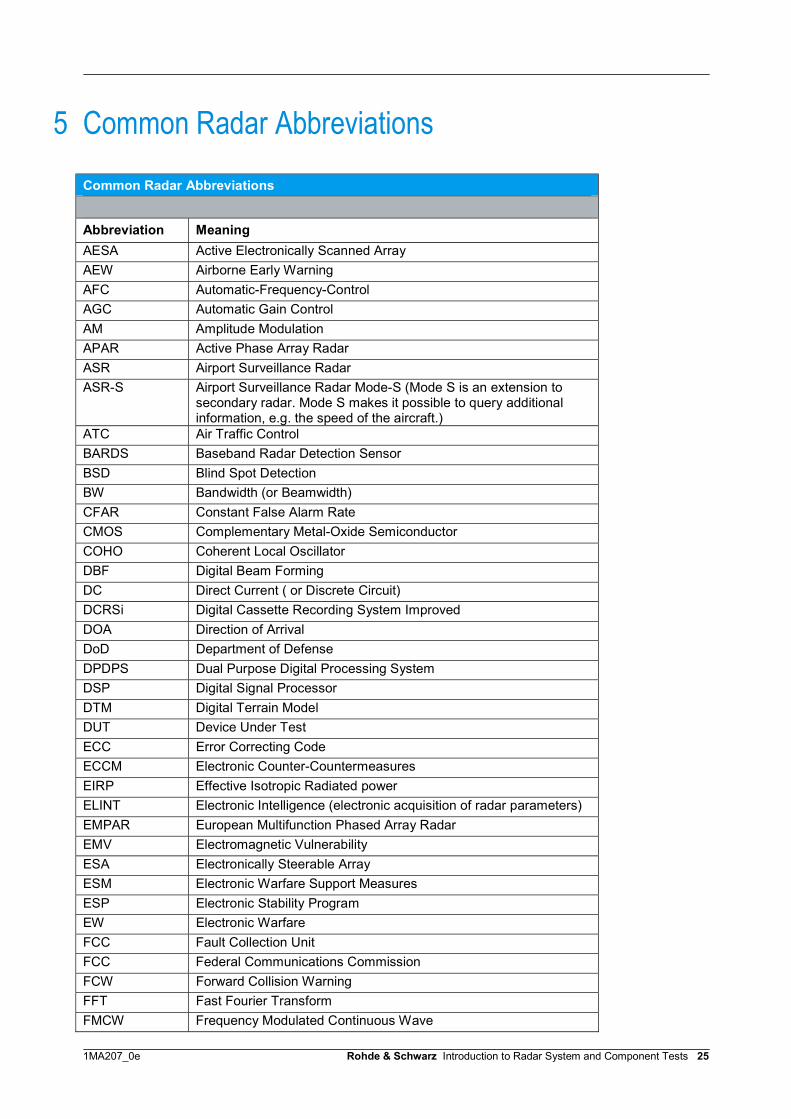
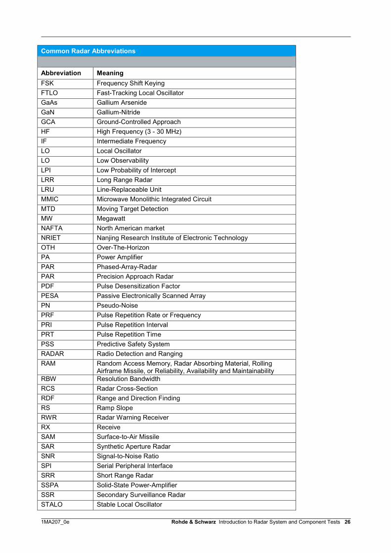
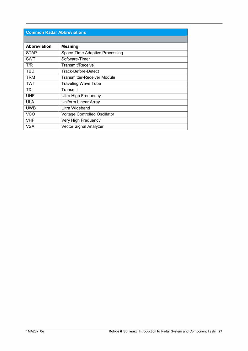
5 Common Radar Abbreviations
Common Radar Abbreviations
Abbreviation MeaningAESA Active Electronically Scanned ArrayAEW Airborne Early WarningAFC Automatic-Frequency-ControlAGC Automatic Gain ControlAM Amplitude ModulationAPAR Active Phase Array RadarASR Airport Surveillance RadarASR-S Airport Surveillance Radar Mode-S (Mode S is an extension to
secondary radar. Mode S makes it possible to query additionalinformation, e.g. the speed of the aircraft.)
ATC Air Traffic ControlBARDS Baseband Radar Detection SensorBSD Blind Spot DetectionBW Bandwidth (or Beamwidth)CFAR Constant False Alarm RateCMOS Complementary Metal-Oxide SemiconductorCOHO Coherent Local OscillatorDBF Digital Beam FormingDC Direct Current ( or Discrete Circuit)DCRSi Digital Cassette Recording System ImprovedDOA Direction of ArrivalDoD Department of DefenseDPDPS Dual Purpose Digital Processing SystemDSP Digital Signal ProcessorDTM Digital Terrain ModelDUT Device Under TestECC Error Correcting CodeECCM Electronic Counter-CountermeasuresEIRP Effective Isotropic Radiated powerELINT Electronic Intelligence (electronic acquisition of radar parameters)EMPAR European Multifunction Phased Array RadarEMV Electromagnetic VulnerabilityESA Electronically Steerable ArrayESM Electronic Warfare Support MeasuresESP Electronic Stability ProgramEW Electronic WarfareFCC Fault Collection UnitFCC Federal Communications CommissionFCW Forward Collision WarningFFT Fast Fourier TransformFMCW Frequency Modulated Continuous Wave
1MA207_0e Rohde & Schwarz Introduction to Radar System and Component Tests 26
Common Radar Abbreviations
Abbreviation MeaningFSK Frequency Shift KeyingFTLO Fast-Tracking Local OscillatorGaAs Gallium ArsenideGaN Gallium-NitrideGCA Ground-Controlled ApproachHF High Frequency (3 - 30 MHz)IF Intermediate FrequencyLO Local OscillatorLO Low ObservabilityLPI Low Probability of InterceptLRR Long Range RadarLRU Line-Replaceable UnitMMIC Microwave Monolithic Integrated CircuitMTD Moving Target DetectionMW MegawattNAFTA North American marketNRIET Nanjing Research Institute of Electronic TechnologyOTH Over-The-HorizonPA Power AmplifierPAR Phased-Array-RadarPAR Precision Approach RadarPDF Pulse Desensitization FactorPESA Passive Electronically Scanned ArrayPN Pseudo-NoisePRF Pulse Repetition Rate or FrequencyPRI Pulse Repetition IntervalPRT Pulse Repetition TimePSS Predictive Safety SystemRADAR Radio Detection and RangingRAM Random Access Memory, Radar Absorbing Material, Rolling
Airframe Missile, or Reliability, Availability and MaintainabilityRBW Resolution BandwidthRCS Radar Cross-SectionRDF Range and Direction FindingRS Ramp SlopeRWR Radar Warning ReceiverRX ReceiveSAM Surface-to-Air MissileSAR Synthetic Aperture RadarSNR Signal-to-Noise RatioSPI Serial Peripheral InterfaceSRR Short Range RadarSSPA Solid-State Power-AmplifierSSR Secondary Surveillance RadarSTALO Stable Local Oscillator
1MA207_0e Rohde & Schwarz Introduction to Radar System and Component Tests 27
Common Radar Abbreviations
Abbreviation MeaningSTAP Space-Time Adaptive ProcessingSWT Software-TimerT/R Transmit/ReceiveTBD Track-Before-DetectTRM Transmitter-Receiver ModuleTWT Traveling Wave TubeTX TransmitUHF Ultra High FrequencyULA Uniform Linear ArrayUWB Ultra WidebandVCO Voltage Controlled OscillatorVHF Very High FrequencyVSA Vector Signal Analyzer

1MA207_0e Rohde & Schwarz Introduction to Radar System and Component Tests 28
6 Literature[1] Merrill I. Skolnik,1990, Radar Handbook, Second Edition McGraw-Hill[2] Merrill I. Skolnik,1990, Radar Handbook, Second Edition McGraw-Hill, Chapter 7[3] http://www.radartutorial.eu/index.en.html[4] http://www.radartutorial.eu/rrp.117.html[5] http://de.wikipedia.org/wiki/Synthetic_Aperture_Radar[6] http://keydel.pixelplaat.de/uploads/File/vorlesung07-08/SAR.pdf[7] http://www.h2g2.com/approved_entry/A743807[8] http://www.armedforces.co.uk/releases/raq43f463831e0b7[9] http://www.pa.op.dlr.de/poldirad/BISTATIC/index.html[10] Silent Sentry™Passive Surveillance[11] http://defense-update.com/20110721_super-hornets-future-eo-radar[12] radar-technology-looks-to-the-future.html[13] http://www.radartutorial.eu/06.antennas/an17.en.html[14] http://dl.acm.org/citation.cfm?id=1294551[15] http://en.wikipedia.org/wiki/Barker_code[16] http://prod.sandia.gov/techlib/access-control.cgi/2006/065856.pdf[17] www.google.com/patents/US6965341.pdf[18] David M. Pozar, Microwave Engineering, Third Edition, Wiley[20] http://Inverse Synthetic Aperture Radar Imaging.pdf
7 Additional InformationThis application note is subject to improvements and extensions. Please visit ourwebsite to download new versions. Please send any comments or suggestionsabout this application note to [email protected].
About Rohde & SchwarzRohde & Schwarz is an independent groupof companies specializing in electronics. It isa leading supplier of solutions in the fields oftest and measurement, broadcasting,radiomonitoring and radiolocation, as well assecure communications. Established morethan 75 years ago, Rohde & Schwarz has aglobal presence and a dedicated servicenetwork in over 70 countries. Companyheadquarters are in Munich, Germany.Environmental commitment
● Energy-efficient products● Continuous improvement in
environmental sustainability● ISO 14001-certified environmental
management system
Regional contactEurope, Africa, Middle East+49 89 4129 [email protected]
North America1-888-TEST-RSA (1-888-837-8772)[email protected]
Latin [email protected]
Asia/Pacific+65 65 13 04 [email protected]
China+86-800-810-8228 /[email protected]
This white paper may only be used subjectto the conditions of use set forth in thedownload area of the Rohde & Schwarzwebsite.
R&S® is a registered trademark of Rohde & SchwarzGmbH & Co. KG; Trade names are trademarks of theowners.
Rohde & Schwarz GmbH & Co. KGMühldorfstraße 15 | D - 81671 MünchenPhone + 49 89 4129 - 0 | Fax + 49 89 4129 – 13777
www.rohde-schwarz.com