Embed Size (px)
Citation preview

Introduction to Protection Basics
Principal EngineerBRENT L. CARPER, P.E.
Presented at the35th Annual Hands-On Relay SchoolMarch 12-16, 2017

Agenda HRS schedule and logistics Tips for a great week Introduction to system protection Fundamental concepts Applications Recap

HRS Scheduleand Logistics

MondayMorning (8:00 – 12:00) Todd Hall 116
Introduction Lecture SeriesIntroduction to ProtectionMath for Technicians
Lunch (12:00 – 1:00)
Afternoon (1:00 – 3:00) Sloan 175 Introduction Lecture Series
Relay Coordination PrinciplesLessons Learned from the Field
Afternoon (3:10 – 5:00) EME B54 ABB CO
Evening (5:00 +) Birch & Barley

TuesdayMorning (7:30 – 12:00) Todd Hall (various rooms)
Concurrent Open Lectures12 lectures available – Pick 4
Lunch (12:00 – 1:00)
Afternoon (1:00 – 5:00) EME B54 ABB RC BE1-81O/U BE1-51
Evening (6:30 – 9:00) Supplier’s Showcase

WednesdayMorning (7:30 – 12:00) EME B54
ABB HU
Lunch (12:00 – 1:00)
Afternoon (1:00 – 5:00) EME B54 GE JBCG
Evening (6:00 – 9:00) Social and Banquet

ThursdayMorning (7:30 – 12:00) EME B54
GE CEY51A
Lunch (12:00 – 1:00)
Afternoon (1:00 – 5:00) EME B54 SEL-551
Evening Optional SEL manufacturing plant tour
FridayMorning (7:30 – 10:30) Todd Hall 116
Review the Week CCVT Transients Protection System Misoperations

Tips for a Great Week
Tips Parking and speeding Be on time Watch out for the afternoon snacks Enjoy the evening events Plan around happy hour Embrace variety Talk to other people from other companies

Introduction toSystem Protection

Intro to Power System Protection What: What are we protecting Why: Why do we need protection When: Speed, selectivity, dependability Where: The equipment used to perform protection How: Applying protective relaying

What

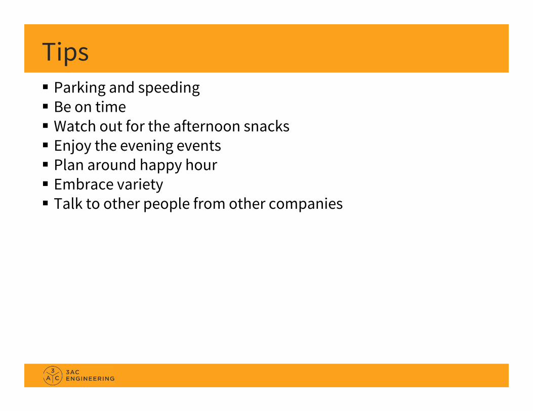
Why

Why

Why
Why

Why

When Speed, selectivity, dependability
Protection must: Detect an abnormal system condition React quickly Respond properly
Not as easy as it sounds! How do we “detect” something happening miles away? How do we react quickly enough? Electricity is traveling at (almost) the
speed of light. How do we ensure that the response action is correct? An incorrect
response could make the abnormal condition worse.

When Speed, selectivity, dependability
Protection must: Detect an abnormal system condition React quickly Respond properly
In general: “abnormal” means a Fault “quickly” means Milliseconds “properly” is accomplished by:
Engineering (relay application, coordination, redundancy and backup) Testing, Commissioning, Maintenance, Verification, Event Analysis

Where The equipment used to perform protection

Where The equipment used to perform protection

Where The equipment used to perform protection

Where

Where Relays are just one component of the “Protection System”
Protective relays which respond to electrical quantities, Communications systems necessary for correct operation of protective
functions Voltage and current sensing devices providing inputs to protective relays, Station dc supply associated with protective functions (including station
batteries, battery chargers, and non-battery-based dc supply), and Control circuitry associated with protective functions through the trip
coil(s) of the circuit breakers or other interrupting devices.
The best Relay Techs (and engineers) have expertise on the entire “Protection System”, not just the relays!
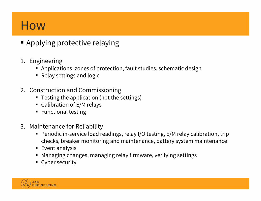
How Applying protective relaying
1. Engineering Applications, zones of protection, fault studies, schematic design Relay settings and logic
2. Construction and Commissioning Testing the application (not the settings) Calibration of E/M relays Functional testing
3. Maintenance for Reliability Periodic in-service load readings, relay I/O testing, E/M relay calibration, trip
checks, breaker monitoring and maintenance, battery system maintenance Event analysis Managing changes, managing relay firmware, verifying settings Cyber security

How How NOT to apply protective relaying…
Super Bowl XLVII (2013)http://entergy‐neworleans.com/content/superbowl/130202_Report.pdf
115kV line relay trip equation errorhttp://www.youtube.com/watch?v=kVXi_0H_ZzMhttp://www.youtube.com/watch?v=gZtJ6Oxcb0o

How
The best Relay Techs (and engineers) have expertise on the entire “Protection System”, not just the relays!
The best Relay Techs (and engineers) do not become famous, and do not end up on YouTube!

FundamentalConcepts

Fundamentals Relays measure Current or Voltage
Magnitude, Phase Angle, or Speed (frequency) Relative to a threshold Relative to another phase Relative to another quantity Rate of change
Examples Fuse reacts to __________ Overcurrent Relay reacts to __________ Ground (Residual) Overcurrent Relay reacts to __________ Distance Relay reacts to __________ Directional Overcurrent Relay reacts to __________ Sync Check Relay reacts to __________

Official Definitions Relay
“An electric device that is designed to respond to input conditions in a prescribed manner and, after specified conditions are met, to cause contact operation or similar abrupt change in associated electric control circuits. Inputs are usually electric, but may be mechanical, thermal, or other quantities or combinations of quantities. Limit switches and similar simple devices are not relays.” (IEEE C37.90)
Protective Relay “A relay whose function is to detect defective lines or apparatus or other
power system conditions of an abnormal or dangerous nature and to initiate appropriate control circuit action.” (IEEE 100).
Fuse “An overcurrent protective device with a circuit-opening fusible part that
is heated and severed by the passage of the overcurrent through it” (IEEE 100)

Practical Definitions In general…
Protective Relays respond to measurements of current and/or voltage of the power system, and have settings or adjustments.
Auxiliary Relays are used with Protective Relays to complete a protection and control scheme. Auxiliary relays respond to control system currents or voltages. They usually do not have adjustments or settings.
Other types of relays and devices may respond to things such as: Pressure, Temperature, Vibration, Light, Position, Liquid Level, Air/Oil Flow, etc. These relays/devices may perform important protective functions.
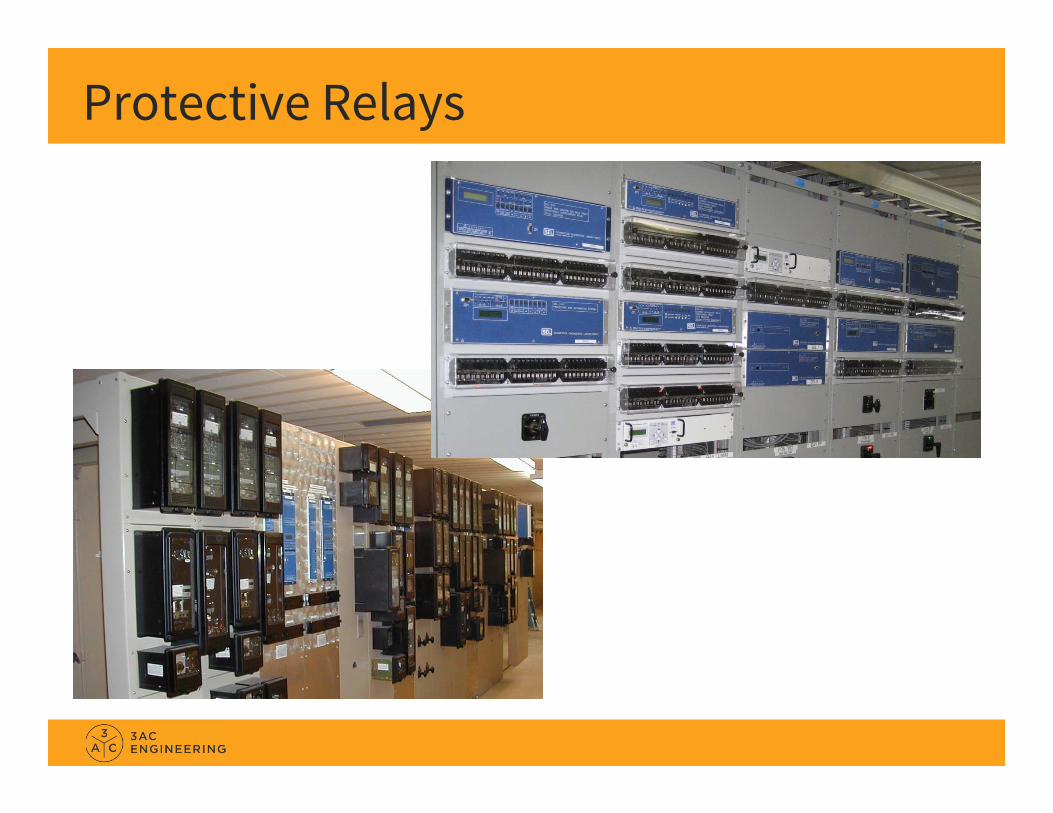
Protective Relays

Auxiliary Relays

Not Relays
Not Relays…but important protective devices.

Relaying? Transformer Sudden Pressure Relay (Rapid Pressure Rise Relay)
and associated Seal-In Relay Protective Relays? Auxiliary Relays?
Traditionally this was a “gray area”… but not anymore!

Relay System

Relay System Relays are just one component of the “Protection System”
Relays Circuit Breakers (or switches) Input Sources (CTs, PTs, Sensors, I/O) DC System (battery) Interconnection (wiring , controls, integration)
The best Relay Techs (and engineers) have expertise on the entire “Protection System”, not just the relays!

Relay Construction Relay Types:
Electromechanical (E/M) Solid State (Analog, Static) Digital (Microprocessor, Numerical, IED, Computerized)
Relay Construction: Single-Function / Multi-Function Single-Phase / Poly-Phase (multi-phase) Drawout Case / Fixed Rack Mount / Panel Mount Projection Mount / Flush Mount / Semi-Flush Mount Front Connected, Back Connected

ReliabilityDependability = Trips every timeSecurity = Never false trips
Increase Dependability by: Increasing sensitivity, increasing number of elements/relays used Redundant relays, dual batteries, dual trip coils Digital relay self monitoring Maintenance, reviewing events
Increase Security by: Correct applications and good design engineering Minimizing “features”, maintaining simplicity Maintaining calibration (e/m and solid-state) and Firmware (digital)
Utility Grade versus Industrial Grade

Reliability?
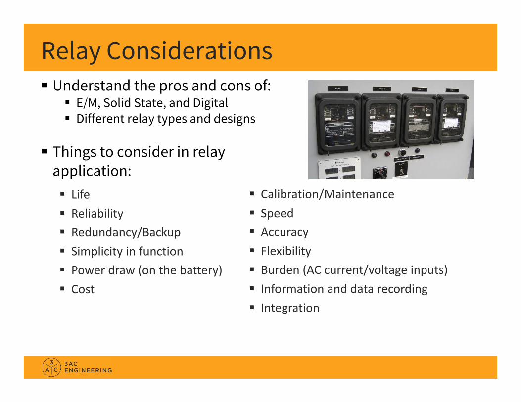
Relay Considerations Understand the pros and cons of:
E/M, Solid State, and Digital Different relay types and designs
Things to consider in relayapplication: Life Reliability Redundancy/Backup Simplicity in function Power draw (on the battery) Cost
Calibration/Maintenance Speed Accuracy Flexibility Burden (AC current/voltage inputs) Information and data recording Integration
ANSI Device Numbers – IEEE C37.2 Hands-On Relay School Clipboard WSU EE494 Handout
This Week 21 Distance Relay 50 Instantaneous Overcurrent Relay 51 AC Time Overcurrent Relay 52 AC Circuit Breaker 67 AC Directional Overcurrent Relay 79 Reclosing Relay 81 Frequency Relay 87 Differential Relay

ANSI Device Numbers – IEEE C37.2 Number prefixes (or suffixes) are used for multiple similar
devices on the same piece of equipment Examples:
101, 201, 301 121, 221, 321 21-1, 21-2, 21-3
A slash (/) is used for multiple functions in a single device Examples:
50/51 27/59

ANSI Device Numbers – IEEE C37.2 Suffixes are used to describe and differentiate devices
Examples: A, B, C – Phase B – Bus BF – Breaker Failure G – Generator or Ground L – Line N – Neutral P – Phase Q – Liquid (oil), Negative Sequence R – Remote T – Transformer V – Voltage X, Y, Z – Auxiliary Devices
Typically the letters I, O, and S are avoided

ANSI Device Numbers – IEEE C37.2 Examples:
87B, 87T, 87L, 87G 187T, 287T 50/51A 71Q 21/67N

ANSI Device Numbers – IEEE C37.2

Compliance North American Electric Reliability Corporation (NERC) Protection and Control (PRC) Reliability Standards
PRC-001 System Protection Coordination PRC-002 Disturbance Monitoring PRC-004 Protection System Misoperations PRC-005 Protection System Maintenance and Testing And so on…
NERC compliance is the best thing to happen to Relay Techs in 140 years of electric power! NERC PRC-005 has made relay testing and commissioning one of the most important functions in the utility industry.

Tools of Protection Electrical theory and math Phasors Symmetrical components Per unit system
Attend other lectures this week on Math, Phasors, and Symmetrical Components

Applications
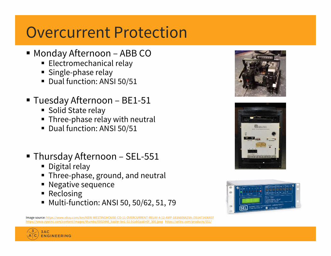
Overcurrent Protection Monday Afternoon – ABB CO
Electromechanical relay Single-phase relay Dual function: ANSI 50/51
Tuesday Afternoon – BE1-51 Solid State relay Three-phase relay with neutral Dual function: ANSI 50/51
Thursday Afternoon – SEL-551 Digital relay Three-phase, ground, and neutral Negative sequence Reclosing Multi-function: ANSI 50, 50/62, 51, 79
Image source: https://www.ebay.com/itm/NEW-WESTINGHOUSE-CO-11-OVERCURRENT-RELAY-4-12-AMP-183A806A25A-/351471436837https://www.npeinc.com/content/images/thumbs/0002448_basler-be1-51-b1eb5pa0n0f_300.jpeg https://selinc.com/products/551/

Overcurrent Protection Most common protection for Distribution
Sometimes used as protection for Transmission Lines Transformers Generators and Machines Busses
But typically as Backup (not primary) protection
Image source: https://www.ebay.com/itm/NEW-WESTINGHOUSE-CO-11-OVERCURRENT-RELAY-4-12-AMP-183A806A25A-/351471436837https://www.npeinc.com/content/images/thumbs/0002448_basler-be1-51-b1eb5pa0n0f_300.jpeg https://selinc.com/products/551/
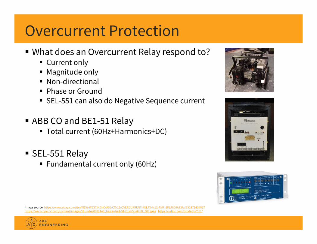
Overcurrent Protection What does an Overcurrent Relay respond to?
Current only Magnitude only Non-directional Phase or Ground SEL-551 can also do Negative Sequence current
ABB CO and BE1-51 Relay Total current (60Hz+Harmonics+DC)
SEL-551 Relay Fundamental current only (60Hz)
Image source: https://www.ebay.com/itm/NEW-WESTINGHOUSE-CO-11-OVERCURRENT-RELAY-4-12-AMP-183A806A25A-/351471436837https://www.npeinc.com/content/images/thumbs/0002448_basler-be1-51-b1eb5pa0n0f_300.jpeg https://selinc.com/products/551/

Overcurrent Protection
Image source: https://www.naswgr.net/wp-content/uploads/2012/05/264C900A07-CO-8-2.jpg
Overcurrent Protection
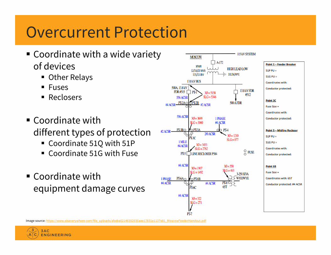
Image source: https://www.eiseverywhere.com/file_uploads/abeba02146302935aee17831e1137e81_MoscowFeederHandout.pdf
Coordinate with a wide variety of devices Other Relays Fuses Reclosers
Coordinate withdifferent types of protection Coordinate 51Q with 51P Coordinate 51G with Fuse
Coordinate withequipment damage curves

Overcurrent Protection
Image source: https://www.eiseverywhere.com/file_uploads/abeba02146302935aee17831e1137e81_MoscowFeederHandout.pdf
Pickup = Sensitivity Typically want the most
sensitivity possible (lowest pickup)
But must be above load
Time Delay = Coordination Set to coordinate with the next
device down-line

Time-Current Coordination Curve (TCC)
Image source: https://www.eiseverywhere.com/file_uploads/ff15529dc8c28a49e2ce97c72ea23840_2017HORSAvistaDistributionPaper.pdf
Curve 1 is a Fuse
Curve 2 is anOvercurrent Relay (51 Only)
Curve 3 is anOvercurrent Relay (50 and 51)
Typical overcurrent settings: Pickup Curve Type Time Delay (for 50/62)
or Time Dial (for 51)

Testing the ABB CO Relay (E/M) Need to test it to set it
Pickup (50) Time Dial (51)
Verify calibration(for commissioning and for maintenance) Pickup (50/51) Curve (51)
3 points for a curve? Test at M=1.5, 4, 20?
Reset Timing (51) Targeting Can automate some of this

Testing the BE1-51 Relay (Solid State) BE1-51 has a microprocessor
Current is measured by an analog circuit uP used for timing and logic
Need to test it to set it Pickup (50) Time Dial (51)
Testing, Commissioning, and Maintenance: Calibration Targeting Power supply

Testing the SEL-551 Relay (Digital) Need to test it to set it? Need to verify calibration?
Commissioning tests: Test I/O Test logic Functional tests In-service checks: STA, MET, SER, ER, COM, DAT, TIM, etc. Sanity check
Maintenance Tests: In-service checks Verify settings Check for firmware updates and service bulletins Test I/O Trip check

Reclosing Tuesday Afternoon
ABB RC Electromechanical work of art!
Thursday Afternoon SEL-551
Uses: Fuse-Saving Schemes Fuse-Blowing Schemes High-Speed Reclosing Schemes Automatic Switching Schemes
Image source: https://library.e.abb.com/public/63af95ea8989a531c1256e7e0031751a/DB41-602e%20%20%20RC%20RCL.pdf http://baslerelectric.azureedge.net/Images/Products/1281.jpg

Reclosing Testing & Commissioning
Logic Timing Application check (sanity check)
Maintenance Timing Output contacts
Image source: https://library.e.abb.com/public/63af95ea8989a531c1256e7e0031751a/DB41-602e%20%20%20RC%20RCL.pdf http://baslerelectric.azureedge.net/Images/Products/1281.jpg
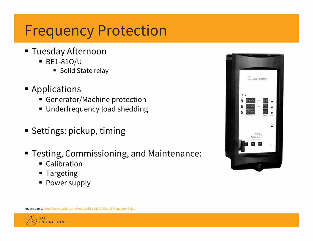
Frequency Protection Tuesday Afternoon
BE1-81O/U Solid State relay
Applications Generator/Machine protection Underfrequency load shedding
Settings: pickup, timing
Testing, Commissioning, and Maintenance: Calibration Targeting Power supply
Image source: http://www.basler.com/Product/BE1-81O-U-Digital-Frequency-Relay

Differential Protection – Transformer Wednesday Morning – ABB HU
Single Phase Transformer Differential Protection (87T) Percentage Differential with Harmonic Restraint 2-winding or 3-winding
Differential = Kirchhoff's Current LawSum of the currents equals zeroWhat comes in, must go out
In the lab Operate, Restraint, Slope Inrush, 2nd Harmonic Restraint
Image source: http://abbimageservice.cloudapp.net/public/images/f88f17a0-6227-4df0-8d16-57b8773ac258/preview.jpg?target=http%3A%2F%2Fabbcloud.blob.core.windows.net%2Fpublic%2Fimages%2Ff88f17a0-6227-4df0-8d16-57b8773ac258%2Fpreview.jpg%3Fcrop%3D0%2C0%2C400%2C400%26width%3D400%26height%3D400&key=3f2d890a68cbb5927c1141ee1415bba7

Directional Overcurrent Protection Wednesday Afternoon – GE JBCG
Electromechanical relay Single-phase (Ground) relay ANSI 67N Instantaneous 67N and Time 67N
Directional Control (Polarization) Dual polarized (zero-sequence current
and/or voltage)
Number corresponds to the curve shape
Image source: https://ssli.ebayimg.com/images/g/Ml4AAOxyFIFR-T5v/s-l1600.jpg

Directional Overcurrent Protection
Image source: https://www.eiseverywhere.com/file_uploads/aaf42a76a5588f69c7a1348d6f77fe0f_Introduction_to_System_Protection-_Protection_Basics.pdf

Directional Overcurrent Protection What does the JBCG relay measure and respond to?
Operates on: Ground current magnitude
Wired as a residual current (sum of all three phases)
Controlled by (polarized by): Phase angle difference between…
Ground current and zero-sequence voltage (Ig lags Vpol by 0 to 60) Ground current and zero-sequence current (Ig leads Ipol by 0 to 40)
Note: Phase angle of the ground current doesn’t matter; just the angle
difference. Magnitude of polarizing quantity doesn’t matter*
* Minimum values for the directional element to operate; maximum values to not damage the relay.

Distance Protection Thursday Afternoon – GE CEY51A
Mho distance relay Three-phase One zone ANSI 21
Distance = Electrical Impedance Current magnitude Voltage magnitude Phase angle between current and voltage
Image source: https://www.gegridsolutions.com/multilin/images/products/cey.gif

Distance Protection
Image source: http://article.sapub.org/image/10.5923.j.eee.20120203.10_001.gif http://www.intechopen.com/source/html/43897/media/image16.png

Recap

Tips Parking and speeding Be on time Watch out for the afternoon snacks Enjoy the evening events Plan around happy hour Embrace variety Talk to other people from other companies Know your schedule and plan ahead Learn everything you can; be engaged Hands-On Relay School can be tremendous for your career Have fun!

Principal EngineerBRENT L. CARPER, P.E.
[email protected]: 509-339-7626cell: 509-339-3848
3AC-Eng.com