Embed Size (px)
Citation preview

© 2011 Xilinx, Inc. All Rights Reserved
Introduction to Partial Reconfiguration Methodology
This material exempt per Department of Commerce license exception TSU
© 2011 Xilinx, Inc. All Rights Reserved
Introduction to Partial Reconfiguration
For Academic Use Only
Objectives
� After completing this module, you will be able to:
– Define Partial Reconfiguration technology
– List common applications for using Partial Reconfiguration
– Define Partial Reconfiguration terminology
– State the Partial Reconfiguration flow
01 - 2

© 2011 Xilinx, Inc. All Rights Reserved
Introduction to Partial Reconfiguration
For Academic Use Only
Outline
� What is Partial Reconfiguration(PR)?
� PR Technology
� PR Terminology
� PR Design Flow
� Summary
01 - 3
© 2011 Xilinx, Inc. All Rights Reserved
Introduction to Partial Reconfiguration
For Academic Use Only
Configuration Port or ICAP
Configuration Port
What is Partial Reconfiguration?
Full
Bit File
Partial
Bit Files
� Partial Reconfiguration is the ability to dynamically modify blocks of logic by downloading partial bit files while the remaining logic continues to operate without interruption.
Fu
nctio
n A
1
Fu
nctio
n B
1
Fu
nctio
n C
1F
un
ction
C2
Fu
nctio
n B
2
Fu
nctio
n A
2F
un
ction
A3
01 - 4

© 2011 Xilinx, Inc. All Rights Reserved
Introduction to Partial Reconfiguration
For Academic Use Only
•
Process 1
Processor Context Switch
Process 2
Partial Bitstream A
FPGA
FPGA Configuration Switch
MMU Sta
ck
PR
regio
n 1
PR
regio
n 2
PR
regio
n N
uP
Process N
Partial Bitstream B
Partial Bitstream N
PR Applications Analogy
01 - 5
© 2011 Xilinx, Inc. All Rights Reserved
Introduction to Partial Reconfiguration
For Academic Use Only
•
Process 1
Processor Context Switch
Process 2
Partial Bitstream A
FPGA
FPGA Configuration Switch
MMU Sta
ck
PR
regio
n 1
PR
regio
n 2
PR
regio
n N
uP
Process N
Partial Bitstream B
Partial Bitstream N
PR Applications Analogy
01 - 6

© 2011 Xilinx, Inc. All Rights Reserved
Introduction to Partial Reconfiguration
For Academic Use Only
Partial Reconfiguration Technology and Benefits
� Partial Reconfiguration enables:
– System Flexibility
• Perform more functions while
maintaining communication links
– Size and Cost Reduction
• Time-multiplex the hardware
to require a smaller FPGA
– Power Reduction
• Shut down power-hungry tasks
when not needed
01 - 7
© 2011 Xilinx, Inc. All Rights Reserved
Introduction to Partial Reconfiguration
For Academic Use Only
System Flexibility:
Communication Hub
� The FPGA can be a communications hub and must remain active
– Cannot perform full reconfiguration due to established links
FPGA
PR
regio
n 1
PR
regio
n 2
PR
regio
n 3 Radio Link
Monitor
Video
LinkBus Link
01 - 8

© 2011 Xilinx, Inc. All Rights Reserved
Introduction to Partial Reconfiguration
For Academic Use Only
Size and Cost Reduction: Time Multiplexing
� Applications need to be able handle a variety of functions
– Supporting many at once can use a great deal of space
� The library of functions use case covers a wide number of applications
– Time-based multiplexing of functions reduces device size requirement
01 - 9
© 2011 Xilinx, Inc. All Rights Reserved
Introduction to Partial Reconfiguration
For Academic Use Only
Power Reduction Techniques with PR
� Board space and resources are limited
– Multi-chip solutions consume extra area, cost, and power
� Many techniques can be employed to reduce power
– Swap out high-power functions for low-power functions when maximum performance is not required
– Swap out black boxes for inactive regions
– Swap high-power I/O standards for lower-power I/O when specific characteristics are not needed
– Time-multiplexing functions will reduce power by reducing amount of configured logic
01 - 10

© 2011 Xilinx, Inc. All Rights Reserved
Introduction to Partial Reconfiguration
For Academic Use Only
� PCIe enumeration time is difficult to meet with larger devices
– 100ms requirement is becoming more challenging to achieve
� Configuration via PCIe is a solution that will meet two specific needs:
– Mechanism for reducing initial configuration time, using compressed bitfile
• Two-stage configuration
allows users to meet
requirement first, then load
remainder of design
– Standard interface as access to ICAP for Partial Reconfiguration
Common Applications:
Configuration via PCIe Interface
Static
FullBit File
PCIe
Black Box
PartialBit File
ICAP
01 - 11
© 2011 Xilinx, Inc. All Rights Reserved
Introduction to Partial Reconfiguration
For Academic Use Only
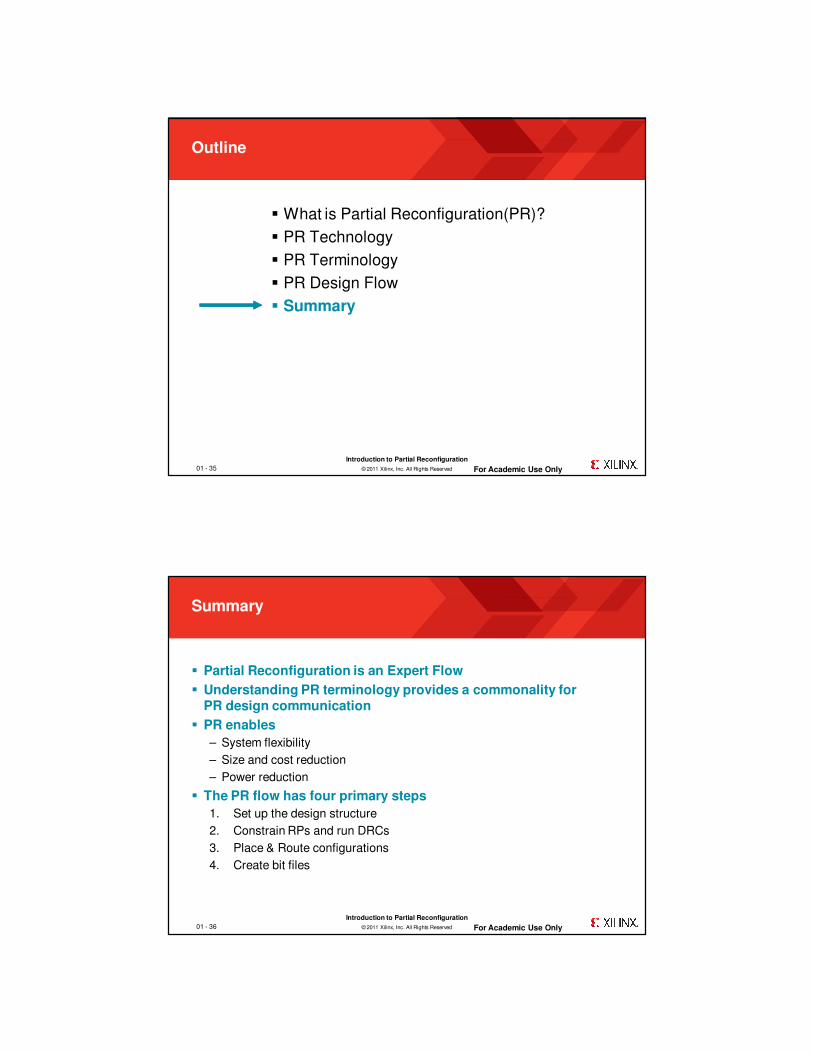
Outline
� What is Partial Reconfiguration(PR)?
� PR Technology
� PR Terminology
� PR Design Flow
� Summary
01 - 12

© 2011 Xilinx, Inc. All Rights Reserved
Introduction to Partial Reconfiguration
For Academic Use Only
Programmability 101
� Think of an FPGA as two layered device:
– Configuration memory layer
– Logic layer
� Configuration memory controls function computed on logic layer
Configuration Memory Layer
Logic Layer
01 - 13
© 2011 Xilinx, Inc. All Rights Reserved
Introduction to Partial Reconfiguration
For Academic Use Only
“Normal” Configuration
Check Sum Config. Data HeaderFPGA
Start
Vcc Rise
Vcc
Stable
Power-on
Reset
Configure
FPGA
Configuration Bitstream
User
Mode
01 - 14

© 2011 Xilinx, Inc. All Rights Reserved
Introduction to Partial Reconfiguration
For Academic Use Only
‘Typical’ Configuration Mode
� Fixed configuration
– Data loads from PROM or other source at power on
– Configuration fixed until the end of the FPGA duty cycle
� Used extensively during traditional design flow
– Evaluate functionality of design as it is developed
Fun
ctio
n
Power
On
Shut
DownTime
Configuration
OverheadDevice
Duty-cycle
01 - 15
© 2011 Xilinx, Inc. All Rights Reserved
Introduction to Partial Reconfiguration
For Academic Use Only
Reconfiguration
� Configuration memory is no longer fixed during the system duty cycle
� Initial bitstream loaded at power-on
� Different, full device bitstreams loaded over time
Fun
ctio
n
Configuration
Overhead
Reconfiguration
Overhead
Power
On
Shut
DownTime
01 - 16
© 2011 Xilinx, Inc. All Rights Reserved
Introduction to Partial Reconfiguration
For Academic Use Only
Partial Configuration
Config. Data
Start
Vcc Rise
Partial Configuration Bitstream
Initial Config.
Complete
Load Partial
Bitstream
FPGA
User
Mode
User
Mode
01 - 17
© 2011 Xilinx, Inc. All Rights Reserved
Introduction to Partial Reconfiguration
For Academic Use Only
Partial Reconfiguration
� Only a subset of configuration data is altered
� But all computation halts while modification is in progress…
� Main benefit: reduced configuration overhead
Fun
ctio
n
Configuration
Overhead
Reconfiguration
Overhead
Power
On
Shut
DownTime
01 - 18

© 2011 Xilinx, Inc. All Rights Reserved
Introduction to Partial Reconfiguration
For Academic Use Only
Dynamic Reconfiguration
� A subset of the configuration data changes…
� But logic layer continues operating while configuration layer is modified…
� Configuration overhead limited to circuit that is changing…
Fun
ctio
n
Configuration
Overhead
Reconfiguration
Overhead
Power
On
Shut
DownTime
01 - 19
© 2011 Xilinx, Inc. All Rights Reserved
Introduction to Partial Reconfiguration
For Academic Use Only
How Can We Reconfigure?
� Initiation of reconfiguration is determined by the designer
– On-chip state machine, processor or other logic
– Off-chip microprocessor or other controller
� Delivery of the partial bit file uses standard interfaces
– FPGA can be partially reconfigured through the SelectMap, Serial or JTAG configuration ports, or the Internal Configuration Access Port
� Logic decoupling should be synchronized with the initiation and completion of partial reconfiguration
– Enable registers
– Issue local reset
01 - 20

© 2011 Xilinx, Inc. All Rights Reserved
Introduction to Partial Reconfiguration
For Academic Use Only
Outline
� What is Partial Reconfiguration(PR)?
� PR Technology
� PR Terminology
� PR Design Flow
� Summary
01 - 21
© 2011 Xilinx, Inc. All Rights Reserved
Introduction to Partial Reconfiguration
For Academic Use Only
Hierarchical Implementation Definitions
� Partition
– A logical block (entity or instance) to be used for design reuse
– User determines implementation versus preservation for each block
� Bottom-up synthesis
– Separate synthesis projects resulting in multiple netlists
– No optimization across projects
� Top-down synthesis; NOT used for Partial Reconfiguration (normal flow)
– One synthesis project where synthesis flattens design for optimization
– Often called flat synthesis
– No support for hierarchical implementation
01 - 22

© 2011 Xilinx, Inc. All Rights Reserved
Introduction to Partial Reconfiguration
For Academic Use Only
Terminology
� Reconfigurable Partition (RP)
– Design hierarchy instance marked by the user for reconfiguration
� Reconfigurable Module (RM)
– Portion of the logical design that occupies the Reconfigurable Partition
– Each RP may have multiple Reconfigurable Modules
� Static Logic
– All logic in the design that is not reconfigurable
� Configuration
– A full design consisting of Static Logic and one Reconfigurable Module for each Reconfigurable Partition
� Partition Pins
– Ports on a Partition; Interface between Static and Reconfigurable Logic
� Proxy Logic
– LUT1 inserted on each Partition Pin to act as anchor points for RP
01 - 23
© 2011 Xilinx, Inc. All Rights Reserved
Introduction to Partial Reconfiguration
For Academic Use Only
Configurations
RP “A”
Static
RP “B”
RP “C”
A1A2
A3
B1B2
C1C2
C3C4
Reconfigurable Modules
� A Configuration is a complete FPGA design
– Consists of Static Logic and one variant for each reconfigurable instance
� Maximum number of RMs for any RP determines minimum number of Configurations required
– Example: Possible Configurations for this design
1. Static + A1 + B1 + C1
2. Static + A2 + B2 + C2
3. Static + A3 + B2 + C3
4. Static + A3 + B2 + C4
– Static Logic and repeated RMs are imported
– Any combination of RMs can be selected to create unique full bit files
01 - 24

© 2011 Xilinx, Inc. All Rights Reserved
Introduction to Partial Reconfiguration
For Academic Use Only
Reconfigurable Elements
� What is reconfigurable?
– Nearly everything in the FPGA
• Slice logic (LUTs, flip-flops, and carry logic, for example)
• Memories (block RAM, distributed RAM, shift register LUTs)
• DSP blocks
• I/O components (IOLOGIC, IODELAY, IDELAYCTRL)
� Logic that must remain in static logic includes
– Clock-modifying blocks (MMCM, DCM, PLL, PMCD)
– Global clock buffers (BUFG)
– Device feature blocks (BSCAN, ICAP, STARTUP, or PCIE, for example)
01 - 25
© 2011 Xilinx, Inc. All Rights Reserved
Introduction to Partial Reconfiguration
For Academic Use Only
Reconfigurable Elements
� Granularity of reconfigurable regions vary by device family– Boundaries recommended, but not required, to align to Clock Regions
– Virtex-6 examples
• Slice region: 40 CLB high by 1 CLB wide
• BRAM region: 8 RAMB36
• DSP region: 16 DSP48
• IOB region: 80 IOB (one bank)
– Virtex-5 examples
• Slice region: 20 CLB high by 1 CLB wide
• BRAM region: 4 RAMB36
• DSP region: 8 DSP48
• IOB region: 40 IOB (one bank)
– Virtex-4 examples
• Slice region: 16 CLB high by 1 CLB wide
• BRAM region: 4 RAMB16 and 4 FIFO16
• DSP region: 8 DSP48
• IOB region: 32 IOB (one bank)
– Bit file sizes for each of these resource types will vary
01 - 26

© 2011 Xilinx, Inc. All Rights Reserved
Introduction to Partial Reconfiguration
For Academic Use Only
Outline
� What is Partial Reconfiguration(PR)?
� PR Technology
� PR Terminology
� PR Design Flow
� Summary
01 - 27
© 2011 Xilinx, Inc. All Rights Reserved
Introduction to Partial Reconfiguration
For Academic Use Only
Flow Differences
01 - 28

© 2011 Xilinx, Inc. All Rights Reserved
Introduction to Partial Reconfiguration
For Academic Use Only
PR Design Flow
01 - 29
© 2011 Xilinx, Inc. All Rights Reserved
Introduction to Partial Reconfiguration
For Academic Use Only
Design Flow:
1. Set Up Design Structure
� Bottom-up synthesis creates netlists for static and reconfigurable logic
– Any synthesis tool can be used
� Create PlanAhead tool PR project
– Import static logic and constraints
� Define partitions and set as reconfigurable
� Import netlists as Reconfigurable Modules for each partition
– Set RMs active to build different configurations
01 - 30

© 2011 Xilinx, Inc. All Rights Reserved
Introduction to Partial Reconfiguration
For Academic Use Only
Design Flow:
2. Constrain RPs and run DRCs
� Floorplan partition regions by creating Pblock rectangles
– Uses AREA_GROUP constraints to assign range
– These declare what will be reconfigured
� Create timing constraints
– Requirements should consider the entire design
– Budget timing on both sides of partition boundary (if needed)
� Run DRCs in the PlanAhead tool
– Specific sets of rules checked for partitions and PR
01 - 31
© 2011 Xilinx, Inc. All Rights Reserved
Introduction to Partial Reconfiguration
For Academic Use Only
Design Flow:
3. Place & Route Configurations
� Uses existing Run command
– Give unique name to each Configuration
• Select the RMs desired for
each RP
– Allows multiple runs to be created for same configuration for exploration
� Strategy: Implement most difficult configuration first
– Once the largest or most timing-critical RMs are resolved, the other scenarios should be easier to manage
� Promote “golden” versions of each RM and static logic
– Import these for subsequent configurations
01 - 32

© 2011 Xilinx, Inc. All Rights Reserved
Introduction to Partial Reconfiguration
For Academic Use Only
Design Flow:
4. Create Bit Files
� First, verify that all PR design rules have been followed
– PR_Verify will check validity of selected Configurations
� Use Bitstream Generation command in PlanAhead
– Will run bitgen on all selected Configurations
• Generates full and partial bit files for each run in implementation directory
– Can be launched for any design run created for any configuration
� Normal simulation and timing analysis can be performed on any Configuration
– A Configuration is a complete FPGA design
– Build any Configuration through Place & Route to simulate that combination of active Reconfigurable Modules
01 - 33
© 2011 Xilinx, Inc. All Rights Reserved
Introduction to Partial Reconfiguration
For Academic Use Only
Configuration Details
� Partial bit files are processed just like full bit files– Bit file sizes will vary depending on region size and resource type
– Contain just address & data, sync & desync words, final CRC value• No startup sequences, DONE flag
� Partial Reconfiguration time depends on two factors:1. Configuration bandwidth
2. Partial bit file size• Estimate in PlanAhead, confirm in Rawbit file
Configuration Mode Max Clock Rate Data Width Max Bandwidth
SelectMap / ICAP 100 MHz 32-bit 3.2 Gbps
Serial Mode 100 MHz 1-bit 100 Mbps
JTAG 66 MHz 1-bit 66 Mbps
01 - 34
© 2011 Xilinx, Inc. All Rights Reserved
Introduction to Partial Reconfiguration
For Academic Use Only
Outline
� What is Partial Reconfiguration(PR)?
� PR Technology
� PR Terminology
� PR Design Flow
� Summary
01 - 35
© 2011 Xilinx, Inc. All Rights Reserved
Introduction to Partial Reconfiguration
For Academic Use Only
Summary
� Partial Reconfiguration is an Expert Flow
� Understanding PR terminology provides a commonality for PR design communication
� PR enables
– System flexibility
– Size and cost reduction
– Power reduction
� The PR flow has four primary steps
1. Set up the design structure
2. Constrain RPs and run DRCs
3. Place & Route configurations
4. Create bit files
01 - 36