Embed Size (px)
Citation preview

Introduction to Embedded Systems
Interrupts + Serial CommunicationsInterrupts + Serial Communications
Lecture 10
Introduction to Embedded Systems
Summary of Previous LectureSummary of Previous Lecture• Timers
• Interrupt vs. polled I/O– Polling the Serial Port – Example with code

Introduction to Embedded Systems
Outline of This LectureOutline of This Lecture• Interrupts (continued)
– Interrupt handlers
– Interrupts on the X-Board
– Installing and writing interrupt handlers
• Serial Communications– Asynchronous protocols
– Serial port and bit transmission
Detours signify material outside of, but indirect/direct background/review material for, the main lecture
(available in the lecture handout on Blackboard)

Introduction to Embedded Systems
Review of ARM ExceptionsReview of ARM Exceptions

Introduction to Embedded Systems
Review of ARM InterruptsReview of ARM Interrupts
• Vector table– Reserved area of 32 bytes at the end of the memory map
– One word of space for each exception type
– Contains a Branch or Load PC instruction for the exception handler
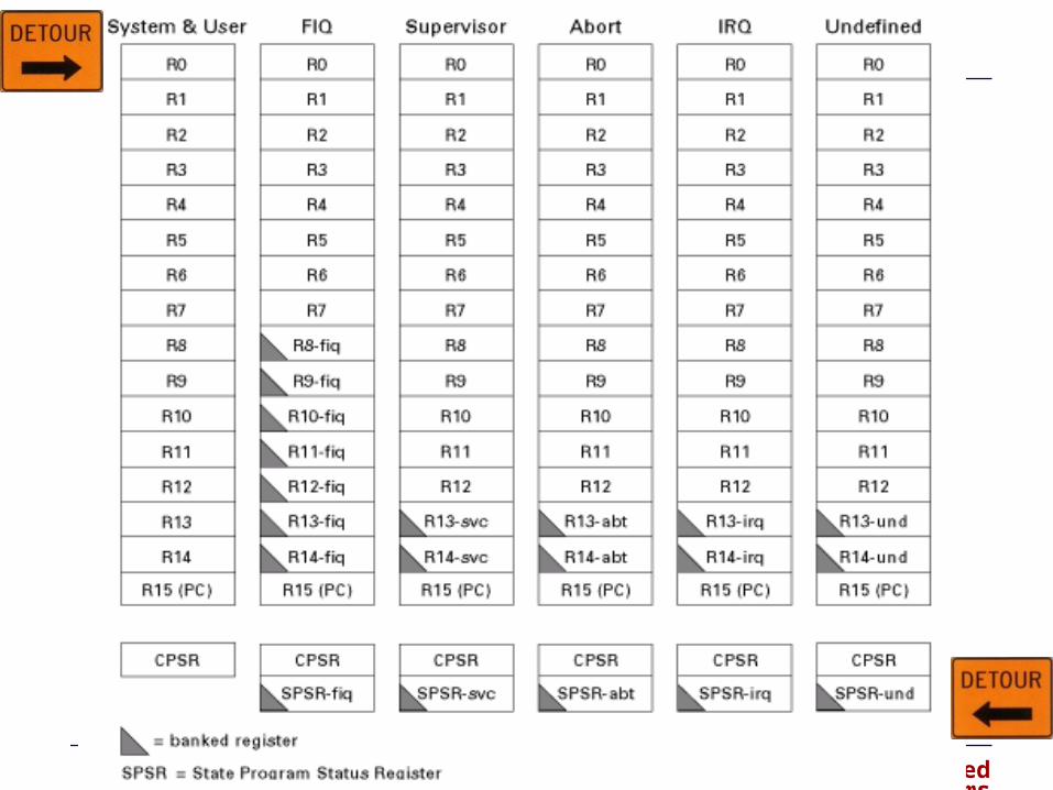
• Exception modes and registers– Handling exceptions changes program from user to non-user mode
– Each exception handler has access to its own set of registers
• Its own r13 = stack pointer
• Its own r14 = link register
• Its own SPSR (Saved Program Status Register)
– Exception handlers must save (restore) other register on entry (exit)
Introduction to Embedded Systems

Introduction to Embedded Systems
What if Exceptions Happen Simultaneously?What if Exceptions Happen Simultaneously?
Introduction to Embedded Systems
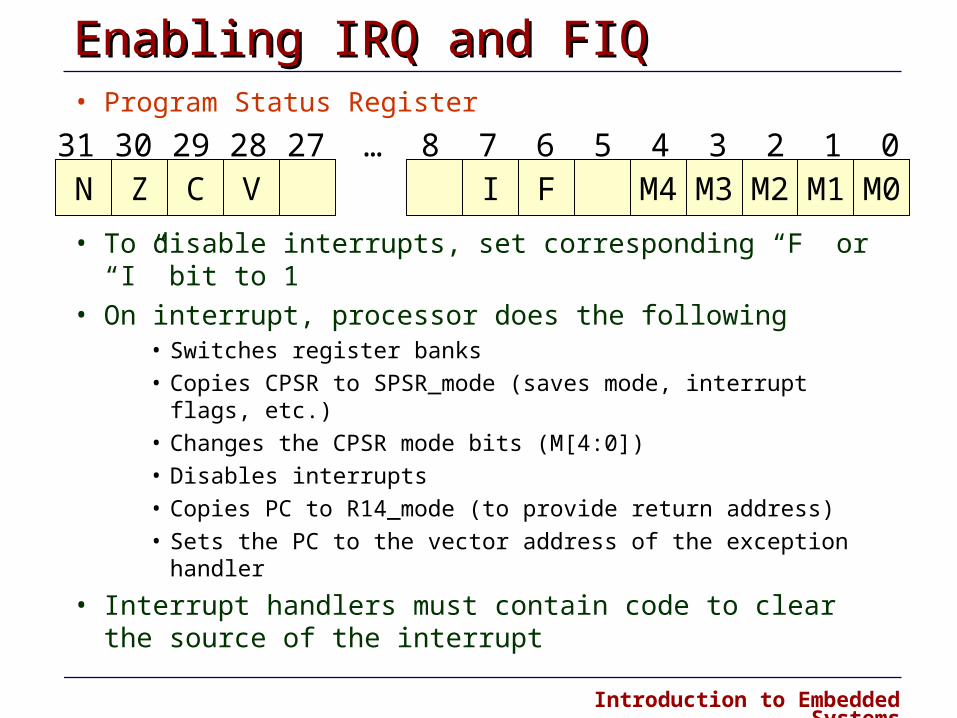
Enabling IRQ and FIQ Enabling IRQ and FIQ • Program Status Register
• To disable interrupts, set corresponding “F” or “I” bit to 1
• On interrupt, processor does the following• Switches register banks
• Copies CPSR to SPSR_mode (saves mode, interrupt flags, etc.)
• Changes the CPSR mode bits (M[4:0])
• Disables interrupts
• Copies PC to R14_mode (to provide return address)
• Sets the PC to the vector address of the exception handler
• Interrupt handlers must contain code to clear the source of the interrupt
N31 30 29 28 27 … 8 7 6 5 4 3 2 1 0
Z C V I F M4 M3 M2 M1 M0
Introduction to Embedded Systems
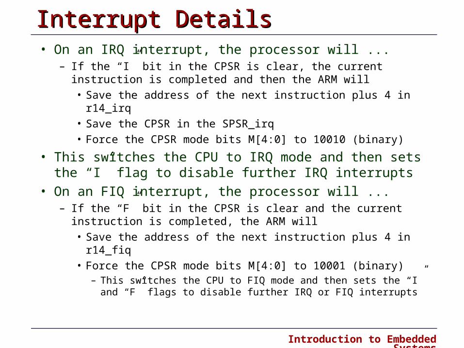
Interrupt Details Interrupt Details • On an IRQ interrupt, the processor will ...
– If the “I” bit in the CPSR is clear, the current instruction is completed and then the ARM will
• Save the address of the next instruction plus 4 in r14_irq
• Save the CPSR in the SPSR_irq
• Force the CPSR mode bits M[4:0] to 10010 (binary)
• This switches the CPU to IRQ mode and then sets the “I” flag to disable further IRQ interrupts
• On an FIQ interrupt, the processor will ... – If the “F” bit in the CPSR is clear and the current instruction is
completed, the ARM will
• Save the address of the next instruction plus 4 in r14_fiq
• Force the CPSR mode bits M[4:0] to 10001 (binary) – This switches the CPU to FIQ mode and then sets the “I” and “F” flags
to disable further IRQ or FIQ interrupts
Introduction to Embedded Systems
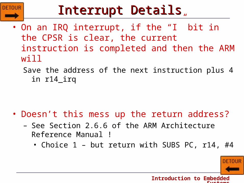
Interrupt Details Interrupt Details • On an IRQ interrupt, if the “I” bit in the CPSR is clear,
the current instruction is completed and then the ARM will Save the address of the next instruction plus 4 in r14_irq
• Doesn’t this mess up the return address?– See Section 2.6.6 of the ARM Architecture Reference
Manual !• Choice 1 – but return with SUBS PC, r14, #4
Introduction to Embedded Systems
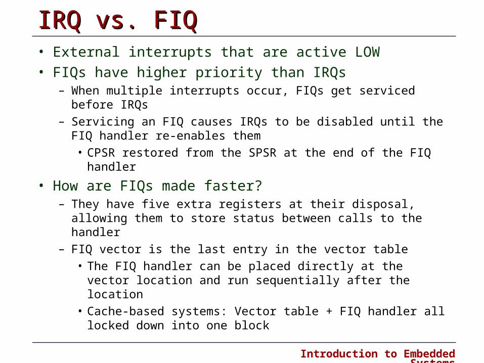
IRQ vs. FIQIRQ vs. FIQ• External interrupts that are active LOW
• FIQs have higher priority than IRQs– When multiple interrupts occur, FIQs get serviced before IRQs
– Servicing an FIQ causes IRQs to be disabled until the FIQ handler re-enables them
• CPSR restored from the SPSR at the end of the FIQ handler
• How are FIQs made faster?– They have five extra registers at their disposal, allowing them to
store status between calls to the handler
– FIQ vector is the last entry in the vector table
• The FIQ handler can be placed directly at the vector location and run sequentially after the location
• Cache-based systems: Vector table + FIQ handler all locked down into one block

Introduction to Embedded Systems
• When an interrupt occurs, the hardware will jump to an “interrupt handler”
Interrupt Handlers Interrupt Handlers
user program user program
IRQ Interrupt handler
Interrupt
• On interrupt, the processor will set the corresponding interrupt bit in the CPSR to disable subsequent interrupts of the same type from occurring.
• However, interrupts of a higher priority can still occur.
Task
IRQ
FIQ
time

Introduction to Embedded Systems
Nested/Re-entrant Interrupts Nested/Re-entrant Interrupts • Interrupts can occur within interrupt handlers
user program user program
IRQ Interrupt handler
Interrupt
• On interrupt, the processor will set the corresponding interrupt bit in the CPSR to disable subsequent interrupts of the same type from occurring.
• However, interrupts of a higher priority can still occur.
Task
IRQ
FIQ
time
FIQ Interrupt handler
SecondInterrupt

Introduction to Embedded Systems
Timing of Interrupts Timing of Interrupts • Before an interrupt handler can do anything, it must save away the
current program's registers (if it touches those registers)
• That's why the FIQ has lots of extra registers to minimize CPU context saving overhead
user program user program
“servicing” interrupt
Interrupt
Task
IRQ
FIQ
time
cpu context saved
cpu context restored
Interrupt response
Interrupt latency

Introduction to Embedded Systems
Interrupts on the X-BoardInterrupts on the X-Board• Intel 80200 Processor has two interrupt inputs
– nIRQ or nFIQ
• Interrupt steering function – Part of the firmware
– Routes the interrupts to the appropriate input
• Interrupt status register– Able to read which interrupts are currently active
• Interrupt Mask register– Used to inhibit an interrupt source from raising the 80200 interrupt
input
• Can change Interrupt Mask or Steering Register at any time
• Question: What happens if an interrupt arrives as you are changing the Interrupt Mask or the Steering Register?

Introduction to Embedded Systems
X-Board Interrupt ControllerX-Board Interrupt Controller
Introduction to Embedded Systems
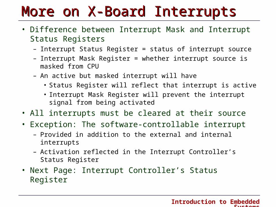
More on X-Board InterruptsMore on X-Board Interrupts• Difference between Interrupt Mask and Interrupt Status
Registers– Interrupt Status Register = status of interrupt source
– Interrupt Mask Register = whether interrupt source is masked from CPU
– An active but masked interrupt will have
• Status Register will reflect that interrupt is active
• Interrupt Mask Register will prevent the interrupt signal from being activated
• All interrupts must be cleared at their source
• Exception: The software-controllable interrupt– Provided in addition to the external and internal interrupts
– Activation reflected in the Interrupt Controller’s Status Register
• Next Page: Interrupt Controller’s Status Register

Introduction to Embedded Systems

Introduction to Embedded Systems
Jumping to the Interrupt Handler Jumping to the Interrupt Handler • Auto-vectored
– Processor-determined address of interrupt handler based on type of interrupt
– This is what the ARM does
• Vectored – Device supplies processor with address of interrupt handler
• Why the different methods? – If multiple devices uses the same interrupt type (IRQ vs. FIQ), in an
Auto-vectored system the processor must poll each device to determine which device interrupted the processor
• This can be time-consuming if there is a lot of devices
– In a vectored system, the processor would just take the address from the device (which dumps the interrupt vector onto a special bus).

Introduction to Embedded Systems
Writing Your Own Interrupt HandlerWriting Your Own Interrupt Handler
• Use the __irq function declaration keyword– Preserves all ATPCS corruptible registers
– Preserves all other registers
– Exits the function cleanly (sets PC and CPSR correctly on exit)
• Cannot be used for re-entrant interrupt handlers (does not save or restore SPSR)
See ADS_Developer_Guide, Section 5.5 for more details
Introduction to Embedded Systems
Serial CommunicationsSerial Communications

Introduction to Embedded Systems
Serial vs. ParallelSerial vs. Parallel• Serial ports
– Universal Asynchronous Receiver/Transmitter (UART): controller
– Takes the computer bus’ parallel data and serializes it
– Transfer rate of 115 Kbps
– Example usage: Modems
• Parallel ports– Sends the 8 bits in parallel
– 50-100 KBps (standard), upto 2 MBps (enhanced)
– Example usage: Printers, Zip drives
PARALLEL
SERIAL

Introduction to Embedded Systems
Data Communication Data Communication • Communications between computer and monitor over serial
line – Data is converted from parallel (bytes) to serial (bits) in the bus
interface
– Bits are sent over wire (TX) to terminal (or back from terminal to computer)
– Receiving end (RX) translates bit stream back into parallel data (bytes)
Parallel-to-SerialConverter
Parallel-to-SerialConverter
CPUCPUSerial-to-Parallel
ConverterSerial-to-Parallel
Converter
RXTX
RX TXComputer
Terminal
SerialLink

Introduction to Embedded Systems
Types of Serial Communication Types of Serial Communication • Two types of configurations
– point to point: two end stations communicate as peers
– multi drop: one device is designated as master (primary), the other devices are slaves (secondaries)
• Physical link can consist of either two or four wires – Two wire link provides signal and ground wires
– Four wire link provides two sets of signal and ground wires
• Full duplex link – One signal wire is for transmitting, the other for receiving
– Closed loop: individual characters are echoed back to transmitter
– Open loop: data is assumed to reach its destination
• Half duplex link – One signal wire is for both transmitting and receiving
TX
RX
Introduction to Embedded Systems
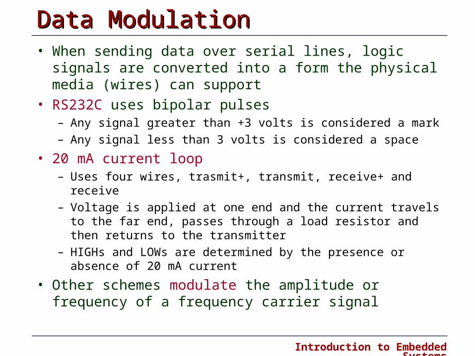
Data Modulation Data Modulation • When sending data over serial lines, logic signals are
converted into a form the physical media (wires) can support
• RS232C uses bipolar pulses – Any signal greater than +3 volts is considered a mark
– Any signal less than 3 volts is considered a space
• 20 mA current loop – Uses four wires, trasmit+, transmit , receive+ and receive
– Voltage is applied at one end and the current travels to the far end, passes through a load resistor and then returns to the transmitter
– HIGHs and LOWs are determined by the presence or absence of 20 mA current
• Other schemes modulate the amplitude or frequency of a frequency carrier signal
Introduction to Embedded Systems
Serial Communications Protocols Serial Communications Protocols • A Communications protocol is a convention for data
transmission that includes such functions as timing, formatting and data representation
• Two categories of protocols: Asynchronous protocols
– successive data appear in the data stream at arbitrary times, with no specific clock control governing the relative delays in data
Synchronous protocols
– each successive datum in a stream of data is governed by a master data clock and appears at a specific interval of time
• Often, protocols deliver serial data in 8 bit characters asynchronous protocols treat each character as an individual message, and the characters appear in the data stream at arbitrary relative times. However, within each character, the bits are transmitted at a fixed predetermined clock rate
Introduction to Embedded Systems
Asynchronous Protocols Asynchronous Protocols
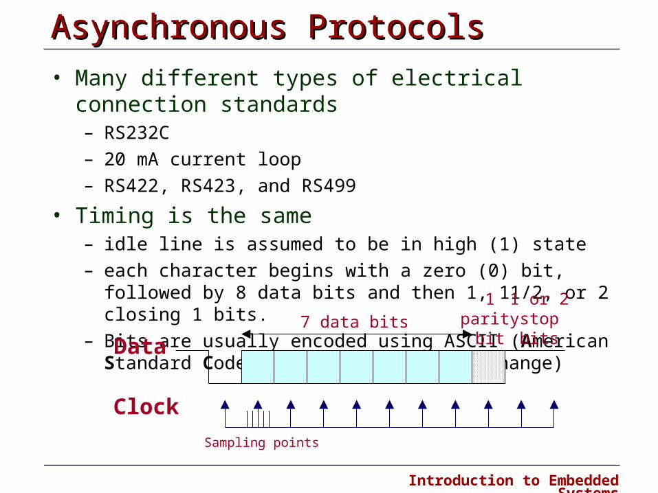
• Many different types of electrical connection standards – RS 232 C
– 20 mA current loop
– RS 422, RS 423, and RS 499
• Timing is the same – idle line is assumed to be in high (1) state
– each character begins with a zero (0) bit, followed by 8 data bits and then 1, 1 1/2, or 2 closing 1 bits.
– Bits are usually encoded using ASCII (American Standard Code for Information Interchange)
Data
Clock
1parity
bit7 data bits
1 or 2stopbits
Sampling points
Introduction to Embedded Systems
Asynchronous Protocols (cont’d) Asynchronous Protocols (cont’d) • Start (stop) bits identify the beginning (end) of each character also
permits receiver to resynchronize local clock to each new character – Remember: characters can begin at arbitrary times
• Bit Sampling – Receiver's clock is not identical to the transmitter's clock – Best if the sample is near the middle of a bit – Not always possible because of clock differences – Receiver clock (in relation to transmitter) cannot gain or lose more than 1/2 bit
per 10 to 11 clock periods (time to transmit one character) • Clocks must be accurate to within 5%
– Most receivers use a fast clock to determine the “middle” of a bit • Typical is 16X clock which can take 16 samples per 1 bit
– Begins by detecting start bit which clears clock counter – Clock counter increments to 16 for each tick of the receiver clock – When the counter reaches 8, it has reached the middle of the bit and takes the
sample

Introduction to Embedded Systems
Serial Port Serial Port
0 1 2 3 4 5 6 7
0 1 2 3 4 5 6 7
0 1 2 3 4 5 6 7
0 1 2 3 4 5 6 7
Clock
RxRegister
TxRegister
FIFO Buffer
FIFO Buffer
0 1 2 3 4 5 6 7
0 1 2 3 4 5 6 7
0 1 2 3 4 5 6 7
0 1 2 3 4 5 6 7
Clock
RxRegister
TxRegister
FIFO Buffer
FIFO Buffer
Processor Peripheral

Introduction to Embedded Systems
Transmitting Bits Transmitting Bits
76 75 6 74 5 6 73 4 5 6 72 3 4 5 6 71 2 3 4 5 6 70 1 2 3 4 5 6 7
n
n+1n+2n+3n+4n+5n+6n+7n+8
Transmitter Receiver0 1 2 3 4 5 6 7
0 1 2 3 4 5 60 1 2 3 4 5
0 1 2 3 40 1 2 3
0 1 20 1
0
n
n+1n+2n+3n+4n+5n+6n+7n+8
Interrupt whenTransmitter (Tx) is empty
Interrupt whenReceiver (Rx) is full
Introduction to Embedded Systems
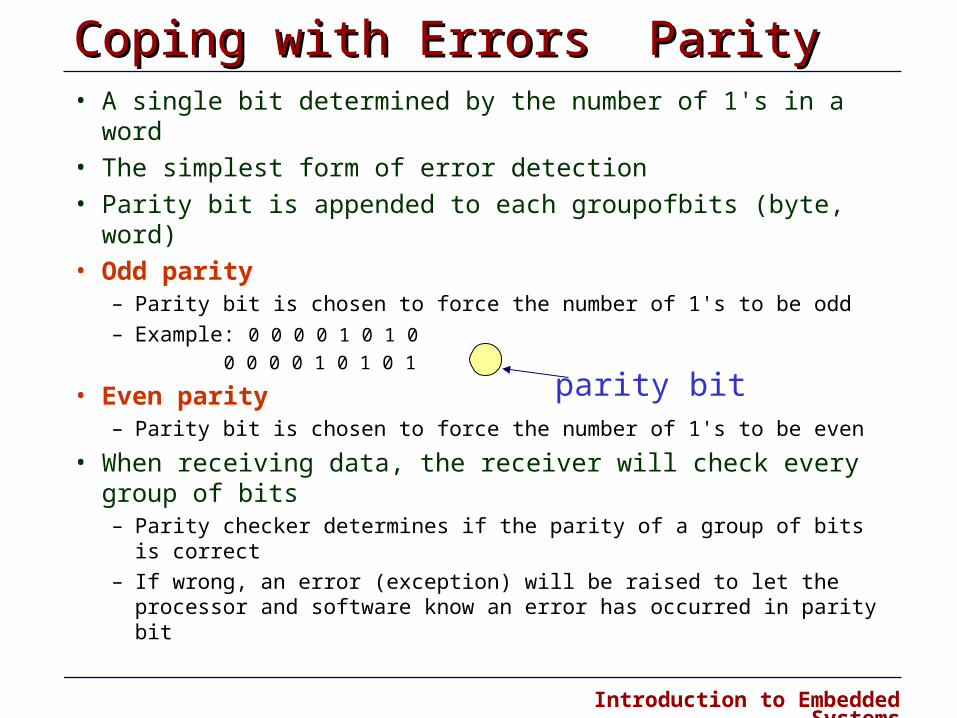
Coping with Errors Parity Coping with Errors Parity • A single bit determined by the number of 1's in a word
• The simplest form of error detection
• Parity bit is appended to each group of bits (byte, word)
• Odd parity – Parity bit is chosen to force the number of 1's to be odd
– Example: 0 0 0 0 1 0 1 0 0 0 0 0 1 0 1 0 1
• Even parity – Parity bit is chosen to force the number of 1's to be even
• When receiving data, the receiver will check every group of bits – Parity checker determines if the parity of a group of bits is correct
– If wrong, an error (exception) will be raised to let the processor and software know an error has occurred in parity bit
parity bit
Introduction to Embedded Systems
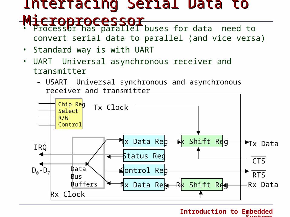
• Processor has parallel buses for data need to convert serial data to parallel (and vice versa)
• Standard way is with UART
• UART Universal asynchronous receiver and transmitter – USART Universal synchronous and asynchronous receiver and transmitter
Interfacing Serial Data to Microprocessor Interfacing Serial Data to Microprocessor
Chip RegSelectR/WControl
Tx Data Reg
Status Reg
Control Reg
Rx Data Reg
Tx Shift Reg
Rx Shift Reg
Tx Clock
Rx Clock
IRQ
CTS
RTSRx Data
Tx Data
DataBusBuffers
D0-D7

Introduction to Embedded Systems
Summary of LectureSummary of Lecture• Interrupts (continued)
– Interrupt handlers
– Nested interrupts
– Interrupts on the X-Board
– Installing and writing interrupt handlers
• Serial Communications– Data communications and modulation
– Asynchronous protocols
– Serial port and bit transmission
• Quiz #3