Embed Size (px)
Citation preview
Introduction to
Electron Microscopy
University of ZurichCenter for Microscopy and Image Analysis
Instrumentation
Courtesy: Andres Kaech
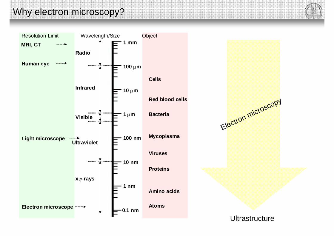
Atoms
1 mm
100 m
10 m
1 m
100 nm
10 nm
1 nm
0.1 nm
Cells
Red blood cells
Bacteria
Mycoplasma
Viruses
Proteins
Amino acids
Radio
Infrared
Visible
Ultraviolet
x,-rays
Human eye
Electron microscope
Light microscope
Resolution Limit Wavelength/Size Object
MRI, CT
Why electron microscopy?
Ultrastructure
Electron microscopy

Why electron microscopy?
10 µm
Rat intestine
Green…F-actinYellow…ß-cateninOrange…Nuclei
Light microscopy Electron microscopy
Microvilli
Adherence junction: ß-catenin visualizedby immunolabelling using „immunogold“
1 µm
Schwarz & Humbel 2007: Methods in Molecular Biology, vol. 369, Electron Microscopy: Methods and Protocols, Second EditionEdited by: J. Kuo © Humana Press Inc., Totowa, NJ

Elektronenmikroskopie ETH Zurich
1 1 µµmm
Specimens courtesy of Bärbel Stecher, Institute of Microbiology, ETH Zurich
Why electron microscopy?
Mouse intestine
Microvilli
GlycocalixJunction
Actin filaments

Elektronenmikroskopie ETH Zürich
500 nm500 nm
Why electron microscopy?
Mouse intestine
Membrane(lipid bilayer)
Actin filaments
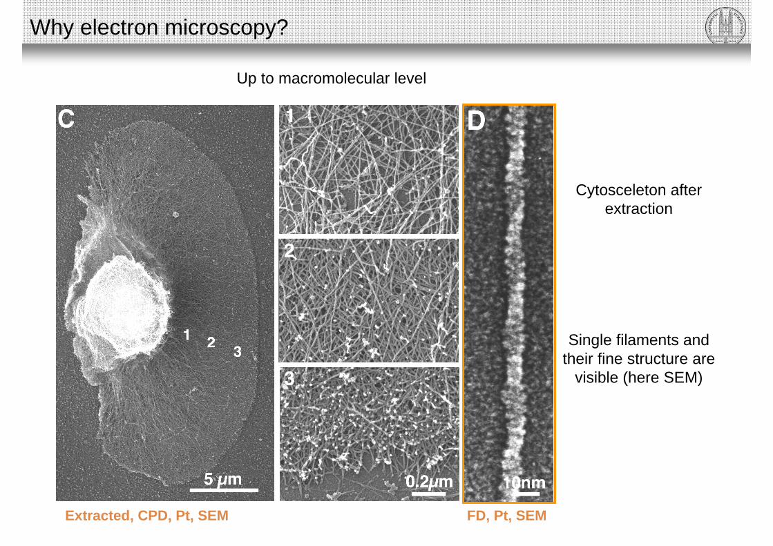
Extracted, CPD, Pt, SEM FD, Pt, SEM
Cytosceleton afterextraction
Single filaments and their fine structure are
visible (here SEM)
Why electron microscopy?
Up to macromolecular level

Time resolutionThe overall design of an electron microscope
is
similar to that of a light microscope.
From photons to electrons

From photons to electrons
Light microscopes
Photons are substituted with electrons
Glass lenses are substituted with electromagnetic and electrostatic lenses
Electron microscope
Photons
Electrons
e-

Wave-particle duality of electrons
Resolution depends on aperture and wavelength (Diffraction limited resolution)
Optical properties(Diffraction, chromatic abberation, spherical abberation, astigmatism etc.)
Abbe’s equation d = 0.61 λ/NA sin nNA
e-
From photons to electrons
Similarities to photons:

λ = wavelengthh = Planck's constant (6.6 X 10⁻²⁷)m = mass of the particlev = velocity of the particle
DeBroglie relation:
The higher the energy of the electrons, the lower the wavelength, the higher the resolution
d (100 kV) = 0.24 nm
For electron microscopes: n ≈ 1 and n*sinα ≈ α
vmh
nmV23.1
Abbe’s equation
sin61.0
nd sin nNA
d = resolution in nmα = half opening angle of objective (in radians)V = accelerating voltage
Resolution EM: nmV
d
753.0
V = accelerating voltage
Electron pathes through potential field
Resolution of electron microscopes
α ≈ 0.01 radians ≈ 0.6 grad

Resolution of biological objects is limited by specimen preparation: Practical resolution: > 1 nm
Acceleration voltages of electrons:
Transmission electron microscopes (TEM): 40 – 1200 kVScanning electron microscopes (SEM): 1 – 30 kV
However:
Effective instrument resolution TEM: 0.1 nm
Effective instrument resolution SEM: 1 nm
Resolution of electron microscopes

The types of electron microscopes
Confocal laser scanning microscope
Light is substituted with electrons
Glass lenses are substituted with electromagnetic and electrostatic lenses
Transmission electron microscope
Wide field microscopy
Scanning electron microscope
Photons
Electrons
Photons
Electrons

Scanning electron microscope (SEM)Transmission electron microscope (TEM)
The types of electron microscopes

Electron gun
Phosphorescent screen
CCD camera
Electromagnetic lens
Electromagnetic lens
Electromagnetic lens
TEM grid
Widefield light microscopeTransmission electron microscope
Condenser lens
Objective lens
Projector lens
Specimen
Illumination
Final image
Lamp
Eye
CCD camera
Glass lens
Glass lens
Glass lens
Slide
The types of electron microscopes
versus

Photomultiplier (Detector) Photomultiplier
Electron gun
Electromagnetic lenses
Electromagnetic lens
Electromagnetic/electrostatic lens
Confocal scanning laser microscopeScanning electron microscope
Beam scanner
Laser
Glass lenses
Mirror
Glass lenses
X-ray, photomultiplier
Detector
Lens system“condenser”
Objective
Specimen
Illumination
The types of electron microscopes
versus

Scanning electron microscope (SEM)Transmission electron microscope (TEM)
High vacuum
Electrons would collide with gas molecules
Electron source (tungsten) would blow
Without vacuum:
The types of electron microscopes

Components of electron microscopes

Electron source (Electron gun)
Light microscope: tungsten filament(bright field)
Electron microscope: tungsten filament(common form)

Filament is heated
Electrons are emitted from the tip
F…FilamentW…Wehnelt electrodeC…Ceramic high voltage insulatorRb…Autobias resistorIe…Electron emission current
Thermionic emission (tungsten, LaB6, Schottky emitter)
Electron source (Electron gun)

Very fine tungsten tip
No heating required (room temperature)
Cold field emission (quantum-mechanical tunneling)
ThermionicTungsten LaB6 Schottky Cold field emission
Material
Heating temp. (K)
Normalized brightness
Required vacuum (Pa)
∆E (eV)
W
2700
LaB6
1800
ZrO/W
1800
W
300
Chromatic aberration!
Ultra highhigh
Electron source (Electron gun)

High voltage
Electron source (Electron gun)

Electromagnetic lenses
Electromagnetic lens of a transmission electron microscope

Electromagnetic lenses
Magnetic field depends on current and number of windings
Note: Force is perpendicular to the plain defined by B and v
v…speed of electronB…magnetic fieldF…resulting force
Electrons are deviated in a magnetic field
I

Image rotation is corrected in modern microscopes
Electromagnetic lenses
Image rotation:

Axial astigmatism of electromagnetic lenses … confusion of the image
Electromagnetic lenses
Most relevant aberration in biological electron microscopy (in particular SEM)
Under focussed imageelliptic deformation
Over focussed imageelliptic deformation
Focuscircle of least confusion
Reasons:
• Contamination of lenses and apertures
• Inhomegenities of the lens
• Charging of specimen

Correction of astigmatism with corrector coils
Electromagnetic lenses
Focus, corrected astigmatismcircle of confusion minimized

Chromatic aberration
Electromagnetic lenses
Spherical aberrationsDue to energy difference of electrons (wavelength)
e- (98 kV)
e- (100 kV)
e- (102 kV)
Curvature and distortion of field

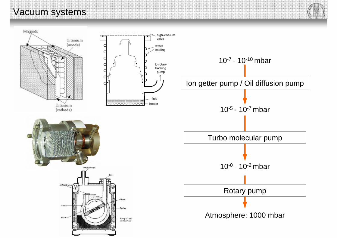
Vacuum systems
Transmission electron microscope
Filament chamberUltra high vacuum: < 10-9 mbar
Specimen chamberHigh vacuum: ~ 10-7 mbar
Viewing chamberHigh vacuum: ~ 10-5 mbar

Vacuum systems
Transmission electron microscope
Ion getter pump / Oil diffusion pump
Turbo molecular pump
Rotary pump
Atmosphere: 1000 mbar
10-5 - 10-7 mbar
10-0 - 10-2 mbar
10-7 - 10-10 mbar
Vacuum systems
Turbo molecular pump
Rotary pump
Atmosphere: 1000 mbar
10-5 - 10-7 mbar
10-0 - 10-2 mbar
10-7 - 10-10 mbar
Ion getter pump / Oil diffusion pump

Vacuum systems
Properties of vacuum systems
Vacuum systems have to be kept clean:
• No volatile components (fatt, oil, water)
• Air-lock for transfer of specimen into vacuum
• Vent with dry nitrogen gas
• High vacuum systems always require a sequence of different vacuum pumps
• Differential vacuum is maintained by small openings between “chambers” and location of the pumps
• Pumping efficiency depends on the gas

Specimen holders and stages
Transmission electron microscope
Goniometer: x, y, z, rSpecimen size:
• 3 mm in diameter!
• Ca. 100 nm in thickness(electron transparent)

Specimen holder
Specimen on a TEM grid
Specimen holders and stages
3 mm3 mm

Specimen holders and stages
Scanning electron microscope
Viewing chamber = Specimen chamber
Gun
Specimen stage (x, y, z, r, tilt)
Objective lens
Stage
Specimen stub
Stub holder
Specimen size:
• 100 mm in diameter
• 2 cm in z-direction (not electron transparent)

Specimen holders and stages
• Stages and goniometer must be extremely stable and precise!
• Any drift will cause unsharp images, in particular at high magnifications
NOTE:
Electron - specimen interactions

Electron – specimen interactions
Inelastic(low angle, E=E0-∆E)
Unscattered(E=E0)
Primary electrons (E0)Backscattered electrons (E=E0)
Elastic(higher angle, E=E0)

Electron – specimen interactions
Primary electrons hit electrons of the specimen atom
Emission of electrons and radiation
Inelastic scattering:
Energy is transferred from the primary electron to the specimen
K
LM
N
1
2
K
LM
N

Electron – specimen interactions
PrimaryPrimary electronselectrons
UnscatteredUnscattered electronselectrons
ElasticallyElastically scatteredscattered electronselectronsInelastically scattered electrons
SecondarySecondary electronselectronsBackscatteredBackscattered electronselectrons
AugerAuger electronselectronsHeat
Cathode luminescenseX-rays
Specimen Interaction volume
SEM analysis
TEM analysis

TEM REM
Electron – specimen interactions

Imaging in the transmission electron microscope
Specimen: Electron transparent(very thin: 100 nm)
Image: 2D projection of a volume• CCD camera• Phosphorescent screen• Conventional photosensitive film
Condenser lens
Objective lens
Projector lens
Specimen
Illumination
Final image

Imaging in the transmission electron microscope
The CCD camera for electron microscopy
Outside the microscope
Inside the microscope (vacuum)
• Electrons need to be converted to photons (scintillator)
• CCD has to be protected from electron bombardment

Contrast formation in TEM
Absorption of electrons
NOTE: All mechanisms occur at the same time (superposition)
Question: Which mechanism is most relevant for biological specimens?
Scattering of electrons
Diffraction and phase contrast
Imaging in the transmission electron microscope

Contrast formation in TEM
Specimen low highdensity
Signal Intensity
Specimen profile
Heat (beam damage)
Imaging in the transmission electron microscope
Absorption of electrons Scattering of electrons Diffraction and phase contrast

Contrast formation in TEM
Specimen low high density
Specimen profile
Objective aperture
Imaging in the transmission electron microscope
Signal Intensity
Absorption of electrons Scattering of electrons Diffraction and phase contrast

Contrast formation in TEM
Specimen
Specimen profile
Objective lensProjective lenses
Objective lensProjective lenses
Imaging in the transmission electron microscope
Image plain
Diffracted ray
Non-diffracted ray
Signal Intensity
Absorption of electrons Scattering of electrons Diffraction and phase contrast

Contrast formation in TEM
Biological specimen consist of light elements:
Absorption weak
Scattering weak
Diffraction and phase weak
Contrast enhancement required:
Treatment with heavy metals (Ur, Pb, Os)!
“NO CONTRAST”
Heavy metals attach differently to different components
Imaging in the transmission electron microscope
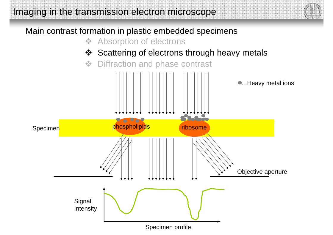
Main contrast formation in plastic embedded specimens
Scattering of electrons through heavy metals
Specimen
Specimen profile
Objective aperture
phospholipids ribosome
Imaging in the transmission electron microscope
…Heavy metal ions
Signal Intensity
Absorption of electrons
Diffraction and phase contrast

Thin section of alga stained with heavy metals (Ur, Pb)
Imaging in the transmission electron microscope
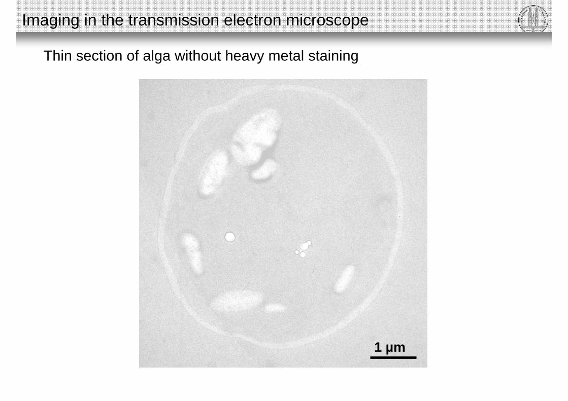
Thin section of alga without heavy metal staining
Imaging in the transmission electron microscope
1 µm

Imaging in the scanning electron microscope

Imaging in the scanning electron microscope
Photomultiplier
Scanning electron microscope
Specimen: Bulk specimen
• Photomultiplier• No CCD camera
Beam scanner
Detector
Lens system“condenser”
Objective
Specimen
Illumination

Imaging in the scanning electron microscope
Scanning and signal detection
Scanning of the specimen

Imaging in the scanning electron microscope
Scanning and signal detection
…Primary electron beam
…Secondary electrons
The focused electron beam is moved from one pixel to another. At everypixel, the beam stays for a defined time and generates a signal (e.g. secondary electrons) which are detected, amplified and displayed on a computer screen.

Imaging in the scanning electron microscope
Scanning and signal detection
The scan generator synchronizes the scanning of the specimen withthe display of the detected, amplified signal.

Imaging in the scanning electron microscope
Achieving higher magnifications:• A smaller area is scanned with the same number of pixels.• The scanned pixels are smaller• The signal is displayed on the computer screen at constant pixel size
Magnifying in scanning electron microscopes
Low mag. High mag.
768 px
1024 px
768 px
1024 px
Object

Imaging in the scanning electron microscope
Signal and detection
R…interaction volume
R

Imaging in the scanning electron microscope
R dependent on density of material (Z) and acceleration voltage of PE (0.1 - 30 kV)
R decreases with increasing Z R increases with increasing acceleration
voltage
R
λ independent on acceleration voltage(but not the number of emitted electrons!)
λ decreases with increasing Z (density)
λ
λ C: 10 – 100 nm λ Cr: 2 – 3 nm λ Pt: 1 – 2 nm
R
Contrast based on SE
Energy of SE independent of acceleration voltage of PE
Imaging in the scanning electron microscope
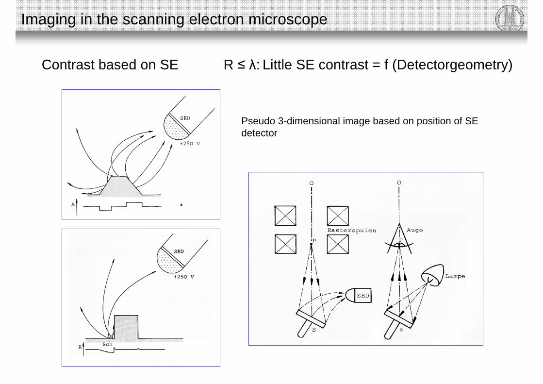
Contrast based on SE R ≤ λ: Little SE contrast = f (Detectorgeometry)
Pseudo 3-dimensional image based on position of SE detector

SE detector(inlens)
SE detector
Imaging in the scanning electron microscope
Contrast based on SE
Leg of an ant, coated with ca. 10 nm Platinum
Virtual light source
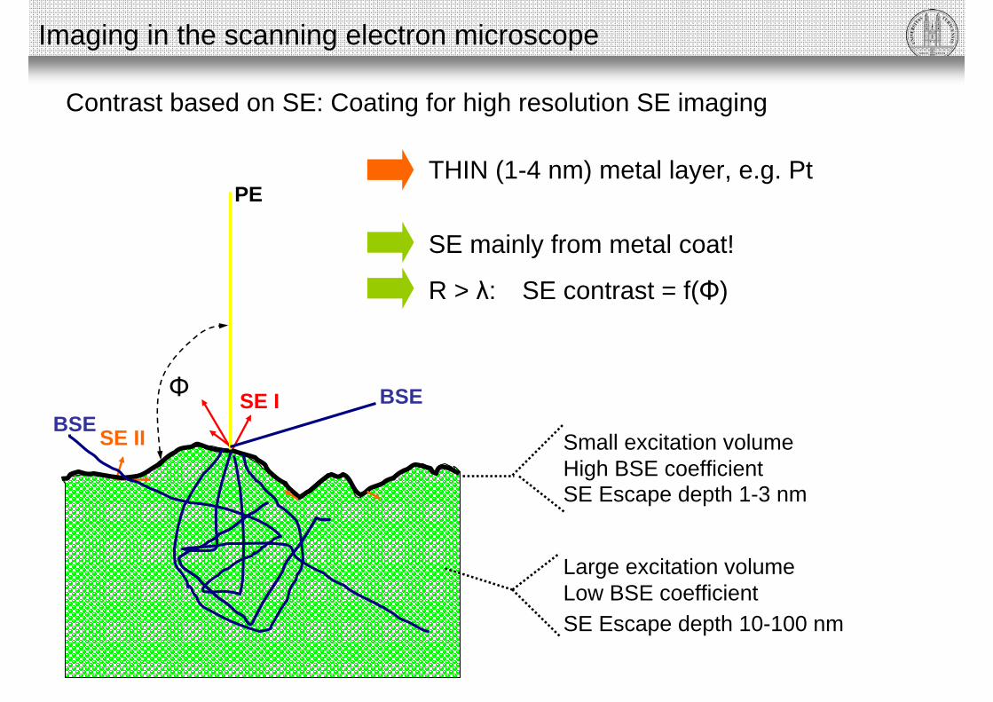
SE Escape depth 10-100 nm
Large excitation volumeLow BSE coefficient
SE mainly from metal coat!
R > λ: SE contrast = f(Φ)
THIN (1-4 nm) metal layer, e.g. Pt
SE Escape depth 1-3 nm
Small excitation volumeHigh BSE coefficient
BSE
SE II
SE IBSE
PE
Imaging in the scanning electron microscope
Contrast based on SE: Coating for high resolution SE imaging
Φ

Freeze-fractured yeast
500 nm
Imaging in the scanning electron microscope
Contrast based on SE: Non-coating vs. coating with heavy metals
Uncoated Coated with 4 nm platinum

Imaging in the scanning electron microscope
R dependent on density of material (Z) and acceleration voltage of PE (0.1 - 30 kV)
Contrast based on BSE
• Useful if specimen is coated with heavy metals
R
Biological material: “No” contrast
BUT:
• Less sensitive to charging (higher energy)• Less topographic contrast• More material contrast
BSE vs. SE

SE signal at 2 kV BSE signal at 30 kV
Fractured plant cell containing metal inclusions in chloroplasts
Imaging in the scanning electron microscope
Contrast SE vs. BSE
Topography Material

SE signal at 20 kV SE signal at 1.7 kV
Yeast freeze-dried, coated with chromium
Imaging in the scanning electron microscope
Contrast SE
Little topography(Signal based on SE II induced by BSE!)
Good topography(Signal based on SE I from surface layer)