Embed Size (px)
Citation preview

Introduction to Dislocation
Edge dislocation
Screw dislocation
Dislocations in crystals
Introduction to Dislocations D. Hull and D.J. Bacon Pergamon Press, Oxford (1984)
Recommended website http://www.tf.uni-kiel.de/matwis/amat/def_en/
Further reading
http://home.iitk.ac.in/~anandh/E-book/Chapter_5b_Crystal_Imperfections_dislocations.ppt
This lecture is adapted from Chapter 5b of Professor Anandh’s eBook)
Dislocations
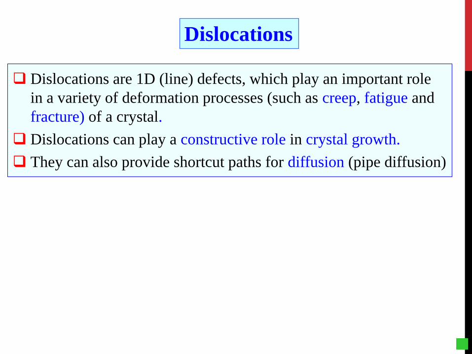
Dislocations are 1D (line) defects, which play an important role in a variety of deformation processes (such as creep, fatigue and fracture) of a crystal.
Dislocations can play a constructive role in crystal growth. They can also provide shortcut paths for diffusion (pipe diffusion)

Understanding the Role of Dislocations in Material Behavior
Consider a dislocation in an infinite crystal
Take into account finite crystal effects
Consider interaction of dislocations with other defects
Stress fields, strain fields, energy etc.
Free surfaces, grain boundaries etc.
Interactions with other dislocations, interstitials, precipitates etc.
Collective behavior and effects of external constrains Long range interactions & collective behavior & external constraints

Slip (Dislocation
motion)
Plastic Deformations in Crystalline Solids
Twinning Phase Transformation Creep Mechanisms
Grain boundary sliding
Vacancy diffusion
Dislocation climb
+ Other Mechanisms
Fivefold twinning in a gold nanoparticle (electron microscope image).

Plastic Deformation of a Crystal by Shear Sh
earin
g st
ress
()τ
Displacement
Sinusoidal relationship
Realistic curve
Considering the shearing of an entire plane of atoms over one another, which causes a plastic deformation by shear.
Initial configuration Final configuration
Entire row of atoms sliding past another

As a first approximation, the stress-displacement curve can be written as
At small displacements, Hooke’s law should apply
For small x/b
Hence the maximum shear stress at which slip should occur
If b ~ a

The shear modulus of metals is in the range 20 – 150 GPa
DISLOCATIONS
However, experimental shear stress is only 0.5 – 10 MPa i.e. (Shear stress)theoretical > 100 × (Shear stress)experimental !!!
Dislocations severely weaken the crystal
The theoretical shear stress will be in the range 3 – 30 GPa
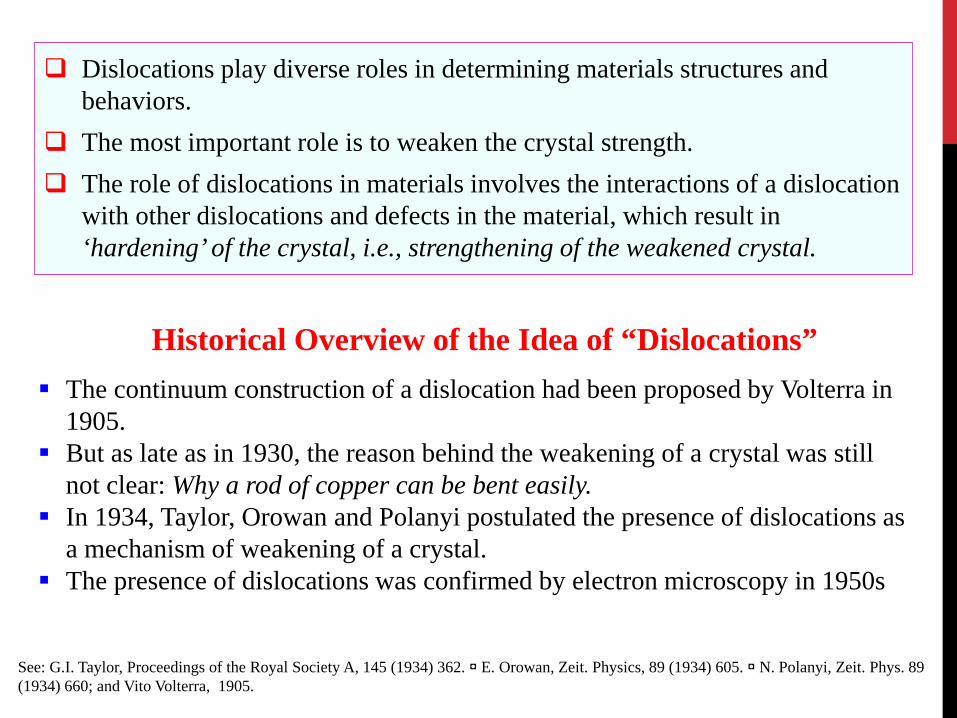
Dislocations play diverse roles in determining materials structures and behaviors.
The most important role is to weaken the crystal strength. The role of dislocations in materials involves the interactions of a dislocation
with other dislocations and defects in the material, which result in ‘hardening’ of the crystal, i.e., strengthening of the weakened crystal.
The continuum construction of a dislocation had been proposed by Volterra in 1905.
But as late as in 1930, the reason behind the weakening of a crystal was still not clear: Why a rod of copper can be bent easily.
In 1934, Taylor, Orowan and Polanyi postulated the presence of dislocations as a mechanism of weakening of a crystal.
The presence of dislocations was confirmed by electron microscopy in 1950s
See: G.I. Taylor, Proceedings of the Royal Society A, 145 (1934) 362. ◘ E. Orowan, Zeit. Physics, 89 (1934) 605. ◘ N. Polanyi, Zeit. Phys. 89 (1934) 660; and Vito Volterra, 1905.
Historical Overview of the Idea of “Dislocations”
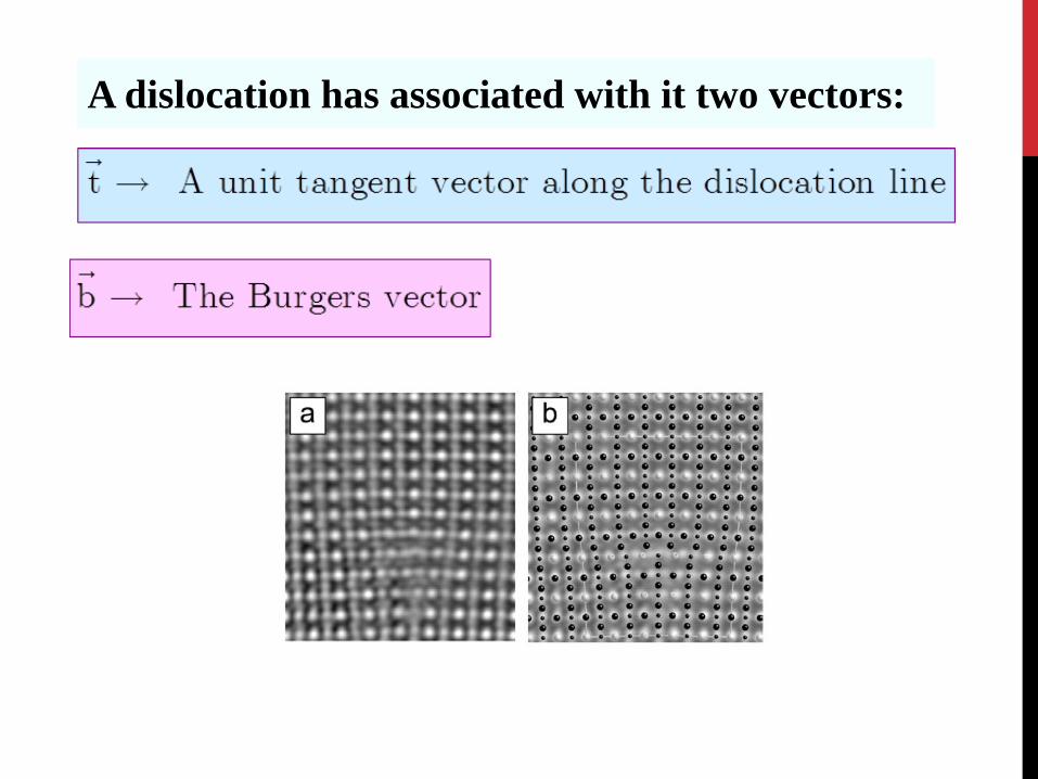
A dislocation has associated with it two vectors:

Edge Dislocation Determination of Burgers vector in a dislocated crystal using Right Hand Finish-to-Start Rule (RHFS) In a perfect crystal, make a circuit (e.g. 8 atomic steps to right, 7 down, 8 left & 7
up). The circuit is Right Handed. Do the same in the same in the dislocated crystal. The ‘missing link’ (using some
convention like RHFS) is the Burgers vector.
RHFS: Right Hand Finish to Start convention Note: the circuit is drawn away from the dislocation line

The edge dislocation is NOT the ‘extra half-plane’, neither the ‘missing half-plane’. It is the line between the ‘extra’ and the ‘missing’ half-planes.
The regions far away from the dislocation line are perfect → all the ‘deformation’ is concentrated around the dislocation line.
The stress field of the dislocation is a ‘long range’ field.
Understanding the Edge Dislocation
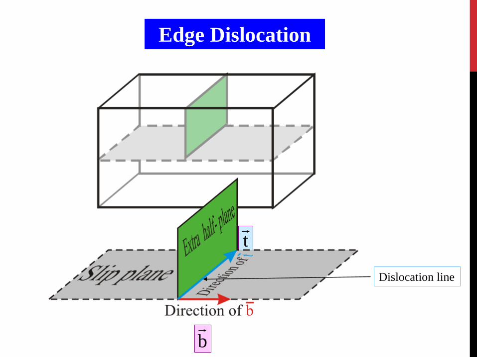
Edge Dislocation
t
b
Dislocation line

Slipped part
of the crystal
Unslipped part
of the crystal
Edge dislocation can be considered as a boundary between the slipped and the unslipped parts of the crystal lying over a slip plane*
* this is just a way of visualization and often the slipped and unslipped regions may not be distinguished
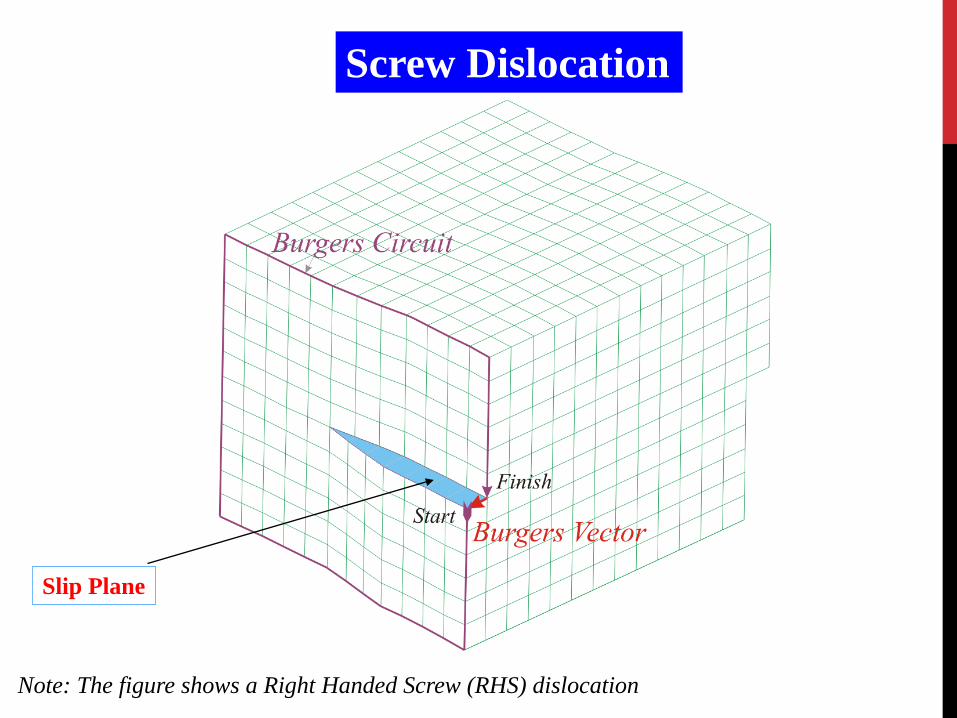
Screw Dislocation
Note: The figure shows a Right Handed Screw (RHS) dislocation
Slip Plane

Dislocation can be considered as the boundary between the slipped and the unslipped parts of the crystal lying over a slip plane.
For an edge dislocation, the intersection of the extra half-plane of atoms with the slip plane defines the dislocation line.
Direction and magnitude of slip is characterized by the Burgers vector of the dislocation .
The Burgers vector can be determined by the Burgers Circuit. The right hand screw (finish to start) convention is used for determining the direction of the Burgers vector.
As the periodic force field of a crystal requires that atoms must move from one equilibrium position to another, which implies that b connects one lattice position to another for a full dislocation.
Dislocations tend to have as small a Burgers vector as possible. Dislocations are non-equilibrium defects and would leave the crystal if
given an opportunity
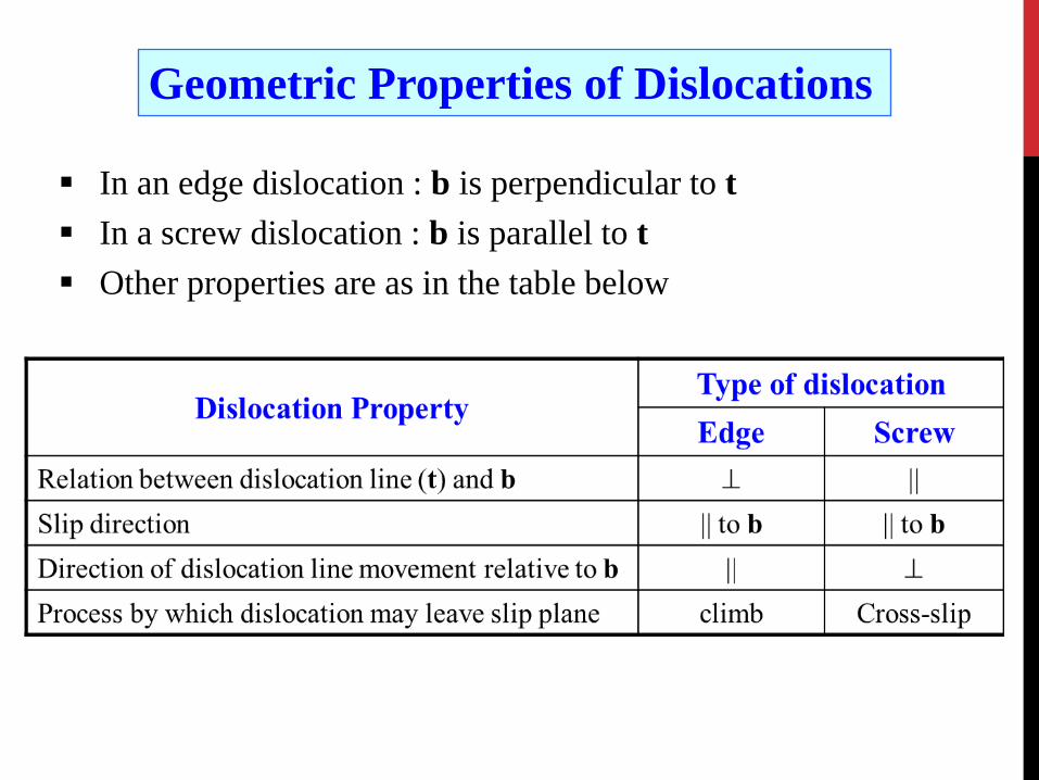
Geometric Properties of Dislocations
In an edge dislocation : b is perpendicular to t In a screw dislocation : b is parallel to t Other properties are as in the table below

EDGE
DISLOCATIONS
MIXED SCREW
Under an observation of Al film with TEM, one usually finds curved dislocation lines, indicating that dislocations have a mixed character and ideal Edge and Screw dislocations are extremes.
The character of the dislocation will change from position to position along the dislocation line.
Under special circumstances Pure Edge, Pure Screw or a Mixed Dislocation with a fixed percentage of edge character can form. For example, in a GeSi epitaxial film on Si substrate, 60° misfit dislocations can form, where the dislocation lines are straight with the angle between b and t being 60°).

Except in special circumstances, dislocations tend to have mixed edge and screw character.
For a curved dislocation, the edge and screw character can change from point to point.
In a dislocation loop, only ‘points’ have pure edge or pure screw character Edge: b ⊥ t Screw: b || t
Mixed Dislocations Dislocations with mixed edge and screw character
Vectors defining a dislocation
b +ve Edge −ve Edge
RHS
LHS Slip Plane
Red line is the loop

Except for points S and E, the remaining portion of the dislocation line has a mixed character
Mixed Dislocations
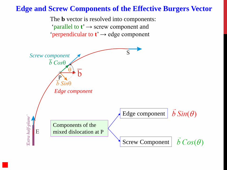
Edge and Screw Components of the Effective Burgers Vector The b vector is resolved into components: ‘parallel to t’ → screw component and ‘perpendicular to t’ → edge component
Components of the mixed dislocation at P
Screw Component
Edge component
Edge component
Screw component

Dislocations can move under an externally applied stress. Two possible motions of a dislocation: Glide and Climb. Local shear stresses on the slip plane can drive the motions of
dislocations. The minimum stress required to move a dislocation is called the Peierls-Nabarro (PN) stress.
Dislocations may also move under the influence of other internal stress fields produced by other dislocations, precipitates, or those by phase transformations etc.
Dislocations are attracted by free-surfaces and interfaces with softer materials and may move because of the attractive Image Force.
In any case, the Peierls stress must be exceeded for the dislocation to move. The value of the Peierls stress is different for the edge and the screw dislocations.
Plastic deformation is due to that the dislocation moves and leaves the crystal. When the dislocation leaves the crystal, a surface step with a height ‘b’ is created and the stress and energy stored in the crystal due to the dislocation is relieved.
Motion of Dislocations
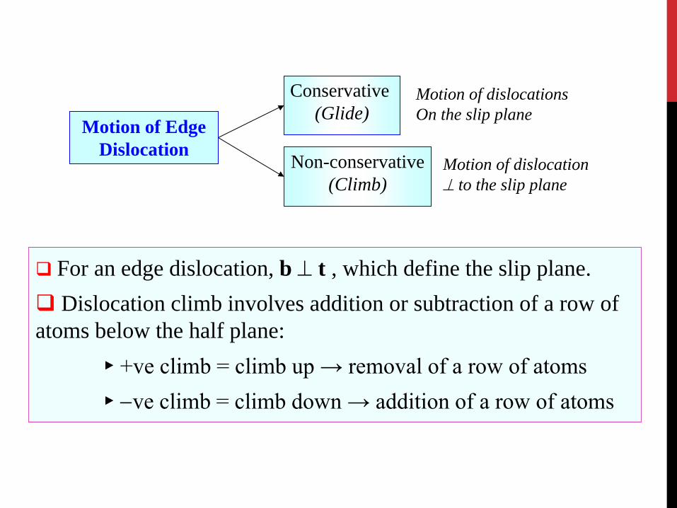
For an edge dislocation, b ⊥ t , which define the slip plane. Dislocation climb involves addition or subtraction of a row of atoms below the half plane: ► +ve climb = climb up → removal of a row of atoms ► −ve climb = climb down → addition of a row of atoms
Motion of Edge Dislocation
Conservative (Glide)
Non-conservative (Climb)
Motion of dislocations On the slip plane
Motion of dislocation ⊥ to the slip plane

Edge Dislocation Glide
Surface step (atomic dimensions)
Motion of an edge dislocation leading to the formation of a step (of ‘b’)
Shear stress

Motion of a Screw
Dislocation Leading to a
Step of b
Note: Schematic diagrams
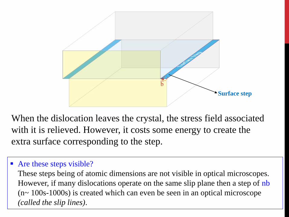
Surface step
When the dislocation leaves the crystal, the stress field associated with it is relieved. However, it costs some energy to create the extra surface corresponding to the step.
Are these steps visible? These steps being of atomic dimensions are not visible in optical microscopes. However, if many dislocations operate on the same slip plane then a step of nb (n~ 100s-1000s) is created which can even be seen in an optical microscope (called the slip lines).

The ‘first step’ of plastic deformation of a crystal is a dislocation leaving the crystal, leading to the formation of a step.
For continued plastic deformation, many more dislocations continue to move and leave the crystal. Any impediments to the motion of a dislocation will lead to ‘hardening’ of the crystal and would stop plastic deformation, such as the pinning of a dislocation.
Once a dislocation has been pinned, it can either ‘break down the barrier’ or ‘bypass’ the barrier.
Bypassing the barrier can occur via mechanisms such as: Climb Cross Slip ….
In climb and cross slip, the dislocation leaves its ‘current’ slip plane and moves to another slip plane, thus avoiding the barrier. These processes (climb and cross slip) can occur independent of the pinning of the dislocation!
Dislocations leaving the slip plane

Dislocation leaving/changing the slip plane
Screw Dislocation
Edge Dislocation Climb
Cross Slip
Non-conservative: involves mass transport
Conservative

Dislocation line cannot end inside the crystal. It must • Ends on a free surface of the crystal • Ends on an internal surface or interface • Form a loop • Ends in a node
A node is the intersection point of more than two dislocations. The vectorial sum of the Burgers vectors of dislocations meeting at a node = 0
Where can a dislocation line end?

Continuum calculations of dislocation-related stress fields and displacement fields are based on elastic continuum theories, which are valid to within a few atomic spacing (i.e. the continuum description fails only within about 5 atomic diameters/Burgers vector).
A continuum description of a dislocation
How to Derive the Deformation Energy of a Dislocation?
Volterras Scheme: An arbitrary deformation of a body can be deduced by repeating two independent processes of combined cuts and shifts.

Volterra constructions of deformations of a hollow cylinder
Perfect cylinder
Screw dislocation
Edge dislocations
Disclinations
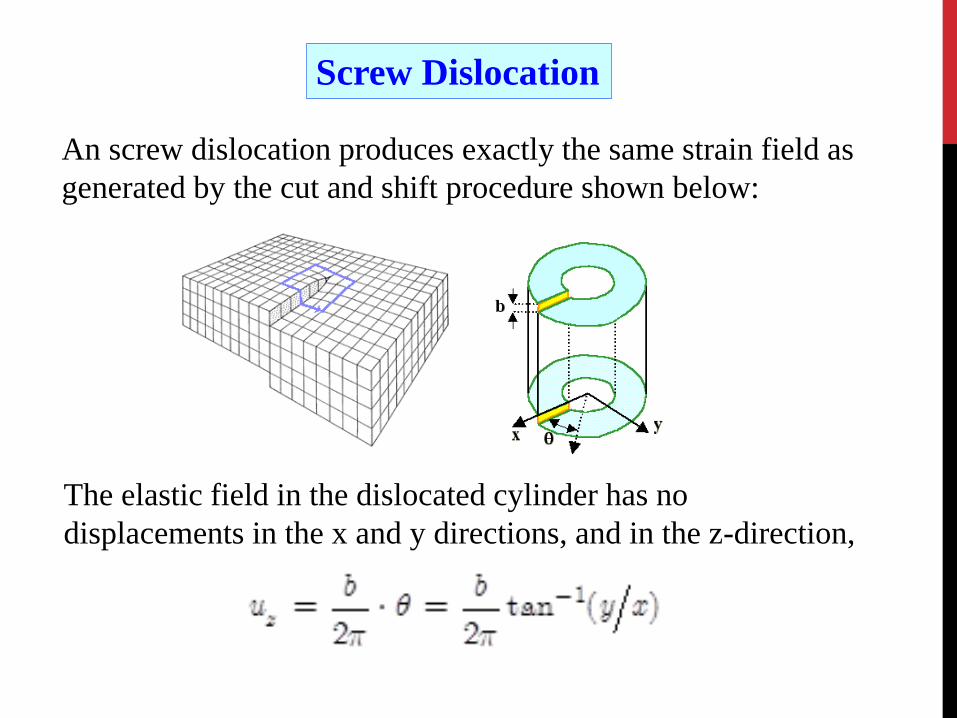
An screw dislocation produces exactly the same strain field as generated by the cut and shift procedure shown below:
The elastic field in the dislocated cylinder has no displacements in the x and y directions, and in the z-direction,
Screw Dislocation
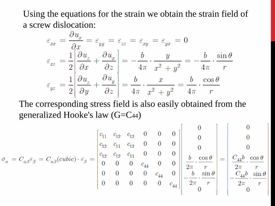
Using the equations for the strain we obtain the strain field of a screw dislocation:
The corresponding stress field is also easily obtained from the generalized Hooke's law (G=C44)

In cylindrical coordinates

The stress field of an edge dislocation can also be represented an appropriate cut in a cylinder. The displacement and strains in the z-direction are zero and the deformation is a "plane strain".
Edge Dislocation
The stress field of the edge dislocation can be depicted as (which has both dilational and shear components).

An edge dislocation produces a compressive stress field around the region of the extra half-plane above the slip plane and a tensile stress field near the region of the missing half-plane below the slip plane.
The core region, which have a singularity at x = 0, y = 0, is ignored in these equations.
The interaction of the stress fields of the dislocations with (i) those from externally applied forces, and (ii) other internal stress fields governs the motion of dislocation.
Stress Fields of Edge Dislocations

The region near the dislocation has stresses of the order of Gpa. However, these stresses are the self stresses. In an infinite body, a straight dislocation line cannot move under the action of self stresses alone.
Thus, a dislocation must interact with other defects in the material via these ‘long range’ stress fields.
Position of the Dislocation line → into the plane
Edge dislocation
σyy
286 Å
286
Å
Stress values in GPa
σxx
0
Extra half-plane
Tensile half-space
Compressive half-space

Energy of a Dislocation A dislocation in a crystal distorts the bonds and costs energy to the
crystal. The deformation energy is expressed as Energy per unit length of
dislocation line → Units: [J/m].
An edge dislocation can generate compressive and tensile stress fields, while a screw dislocation can only produce shear stress fields.
The distortions are very large near the dislocation line and the linear elastic description fails. The estimates of this core region range from b to 5b, depending on the crystal in question. The structure and energy of the core has to be computed through other methods and the energy of the core is about 1/10 the total energy of the dislocation.

Energy of a Dislocation The total energy per unit length Eul is the sum of the energy contained in the elastic field, Eel, and the energy in the core, Ecore. The strain energy for a volume element
The best simple value for the core energy is
⇒ Dislocations will have as small a b as possible
Dislocations (in terms of lattice translation)
Full
Partial
b → Full lattice translation
b → Fraction of lattice translation
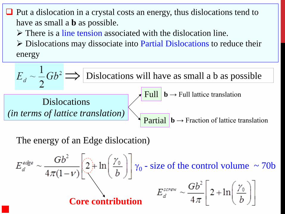
Put a dislocation in a crystal costs an energy, thus dislocations tend to have as small a b as possible. There is a line tension associated with the dislocation line. Dislocations may dissociate into Partial Dislocations to reduce their energy
The energy of an Edge dislocation)
γ0 - size of the control volume ~ 70b
Core contribution

Dissociation of a dislocation
Consider the reaction: 2b → b + b
Change in energy: G(2b)2/2 → 2[G(b)2/2]
= G(b)2 ⇒ The reaction would be favorable
Dislocations dissociate to reduce their energy cost.

Elastic interactions between edge dislocations on the same slip plane can be either Attractive or Repulsive.
Consider two dislocations present on the same slip plane with the extra half-plane on two different sides of the slip plane. One of them is positive and the other is negative.
Interaction between dislocations
Positive edge dislocation Negative edge dislocation
ATTRACTION Can come together and cancel one another
REPULSION
Edge dislocation

Consider a Slip system of <110> {111}, a perfect dislocations can split into partials to reduce the elastic energy.
The dissociation of a dislocation into its partials leaves a Stacking Fault between the two partials on the slip plane.
The two partials repel each other and want to be as far as possible, which leads to a larger faulted area with an increase in energy. Thus, depending on the stacking fault energy, there exists an equilibrium separation between the partials.
The Shockley partial in a CCP crystal has Burgers vectors of (1/6) [211] type, which connect B site to C site and vice-versa.
For a pure edge dislocation in a CCP crystal, the ‘extra half-plane’ consists of two atomic planes. The partial dislocations consist of one ‘extra’ atomic plane each. The Burgers vector of the partial is not perpendicular to the dislocation line.
Dislocations in Cubic Close Packing (CCP) Crystals
(111) Slip plane
b12 > (b2
2 + b32)
½ > ⅓
CCP
21 2116
b = 31 1216
b =
11 1102
b =
AB
C
(111)
21 2116
b = 31 1216
b =
11 1102
b =
AB
C
(111)
Some of the atoms are omitted for clarity
(b22 + b3
2) = 1/6 + 1/6 = 1/3
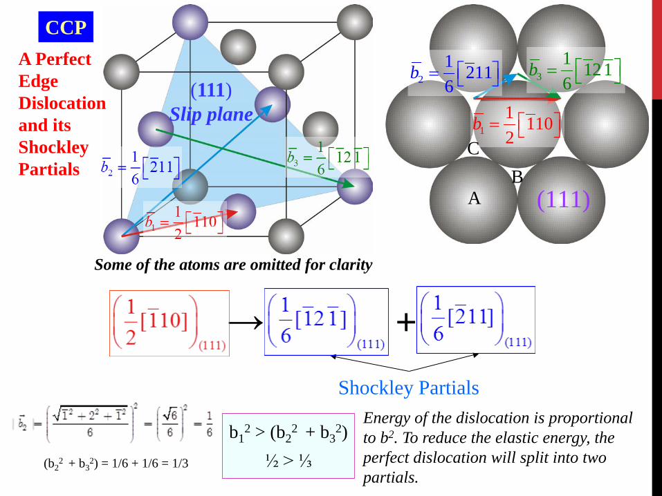
Energy of the dislocation is proportional to b2. To reduce the elastic energy, the perfect dislocation will split into two partials.
A Perfect Edge Dislocation and its Shockley Partials
→ + Shockley Partials

Shockley Partials
Perfect edge dislocation (‘full’ Burgers vector) with two atomic ‘extra-half’ planes
Partial dislocations: each with one atomic ‘extra-half’ plane

The dislocation density is a measure of how many dislocations are present in a quantity of a material.
Dislocation density: the total length of dislocation per unit volume. Hence the units are [m/m3].
Annealed crystal: dislocation density (ρ) ~ 108 – 1010 m/m3 Cold worked crystal: ρ ~ 1012 – 1014 m/m3
As the dislocation density increases the crystal becomes stronger
Typical Values of Dislocation Density

Jogs and Kinks A straight dislocation line can have a break in it: A jog moves it out of the current slip plane (→ to a parallel one) A kink leaves the dislocation on the slip plane
The Jog and the Kink can be considered as a defect in a dislocation line.
Jogs and Kinks can be produced by intersection of straight dislocations.
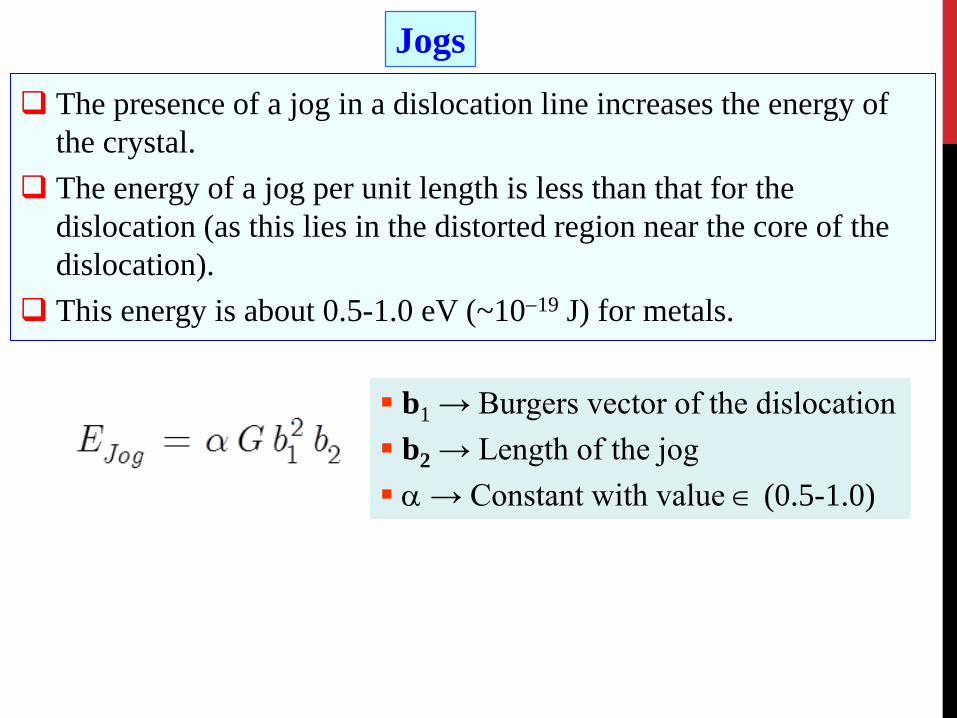
Jogs The presence of a jog in a dislocation line increases the energy of
the crystal. The energy of a jog per unit length is less than that for the
dislocation (as this lies in the distorted region near the core of the dislocation).
This energy is about 0.5-1.0 eV (~10−19 J) for metals.
b1 → Burgers vector of the dislocation b2 → Length of the jog α → Constant with value ∈ (0.5-1.0)
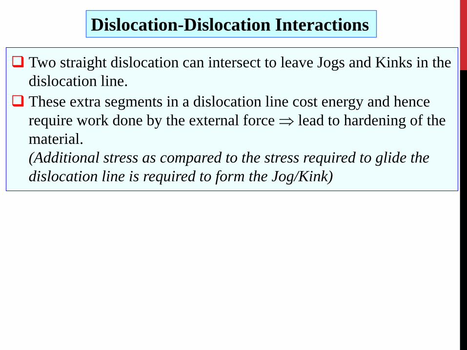
Two straight dislocation can intersect to leave Jogs and Kinks in the dislocation line.
These extra segments in a dislocation line cost energy and hence require work done by the external force ⇒ lead to hardening of the material. (Additional stress as compared to the stress required to glide the dislocation line is required to form the Jog/Kink)
Dislocation-Dislocation Interactions

The jog has edge character and can glide (with Burgers vector = b2) The length of the jog = b1. Edge Dislocation-1 (Burgers vector b1) is unaffected as b2|| t1. Edge Dislocation-2 (Burgers vector b2) → Jog (Edge character) →
Length |b1|.
(1) Edge-Edge Intersection Perpendicular Burgers vector
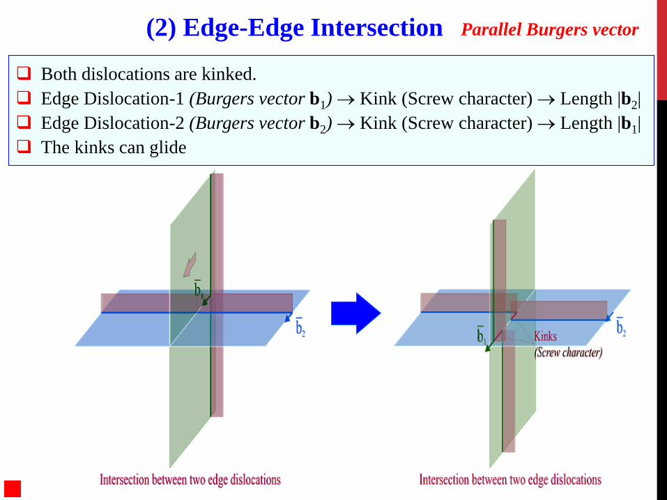
Both dislocations are kinked. Edge Dislocation-1 (Burgers vector b1) → Kink (Screw character) → Length |b2| Edge Dislocation-2 (Burgers vector b2) → Kink (Screw character) → Length |b1| The kinks can glide
(2) Edge-Edge Intersection Parallel Burgers vector
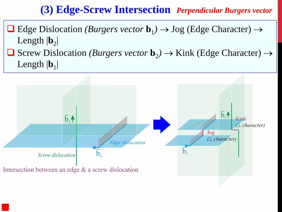
Edge Dislocation (Burgers vector b1) → Jog (Edge Character) → Length |b2|
Screw Dislocation (Burgers vector b2) → Kink (Edge Character) → Length |b1|
(3) Edge-Screw Intersection Perpendicular Burgers vector

Important from plastic deformation point of view Screw Dislocation (Burgers vector b1) → Jog (Edge Character) → Length b2 Screw Dislocation (Burgers vector b2) → Jog (Edge Character) → Length b1 Both the jogs are non conservative
(i.e. cannot move with the dislocations by glide)
(4) Screw -Screw Intersection Perpendicular Burgers vector
The stress field of a dislocation can interact with the stress field of point defects.
Defects associated with tensile stress fields are attracted towards the compressive region of the stress field of an edge dislocation (and vice versa). Higher free-volume at the core of the edge dislocation aids this segregation process.
Solute atoms can segregate in the core region of the edge dislocation → higher stress is now required to move the dislocation (the system is in a low energy state after the segregation and higher stress is required to ‘pull’ the dislocation out of the energy well).
Defects associated with shear stress fields (having a non-spherical distortion field) can interact with the stress field of a screw dislocation.
Dislocation-Point Defect Interactions

Stress values in GPa
σxx Position of the Dislocation line → into the plane
Tensile Stresses
Compressive Stresses
0 stress line Vacancies () No interaction
Vacancies are attracted to the compressive regions of an edge dislocation and are repelled from tensile regions
The behavior of substitutional atoms smaller than the parent atoms is similar to that of the vacancies.
Larger substitutional atoms are attracted to the tensile region of the edge dislocation and are repelled from the compressive regions
Interstitial atoms (associated with compressive stress fields) are attracted towards the tensile region of the edge dislocation and are repelled from the compressive region of the stress field

Point Defect Tensile Region Compressive Region
Vacancy Repelled Attracted
Interstitial Attracted Repelled
Smaller substitutional atom Repelled Attracted
Larger Substitutional atoms Attracted Repelled
Summary of edge dislocation - point defect interactions

ε →
σ→
ε →
σ→
Yield Point Phenomenon
Interaction of the stress fields of dislocations’ with Interstitial atoms’
Schematic
Yield Point Phenomenon
The interaction of interstitial carbon atoms with edge dislocations → leading to their segregation to the core of the edge dislocations is responsible for the Yield Point Phenomenon seen in the tensile test of mild steel specimens
Interstitial Atom at the core

Dislocation- Free surface Interaction → Concept of Image Forces
A dislocation near a free surface experiences a force towards the free surface, which is called the image force.
The force is called an ‘image force’ as the force can be calculated assuming an negative hypothetical dislocation on the other side of the surface. The attractive force between the dislocations (+ & −) is gives the image force.
If the image force exceeds the Peierls stress, then the dislocation can leave the crystal spontaneously without application of external stresses!
Hence, regions near a free surface or nano-crystals can become spontaneously dislocation free. In nanocrystals due to the proximity of more than one surface, many images have to be constructed and the net force is the superposition of these image forces.

Crystals grown under low supersaturation (~1%) the growth rate is considerably faster than that calculated for an ideal crystal
In an ideal crystal surface the difficulty in growth arises due to difficulty in the nucleation of a new monolayer
If a screw dislocation terminates on the surface of a crystal then addition of atoms can take place around the point where the screw dislocation intersects the surface (the step) → leading to a spiral (actually helical) growth staircase pattern
Dislocation and Crystal Growth

Appendix
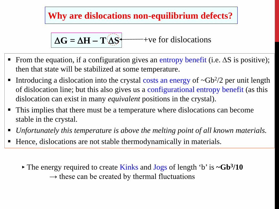
Why are dislocations non-equilibrium defects?
From the equation, if a configuration gives an entropy benefit (i.e. ∆S is positive); then that state will be stabilized at some temperature.
Introducing a dislocation into the crystal costs an energy of ~Gb2/2 per unit length of dislocation line; but this also gives us a configurational entropy benefit (as this dislocation can exist in many equivalent positions in the crystal).
This implies that there must be a temperature where dislocations can become stable in the crystal.
Unfortunately this temperature is above the melting point of all known materials. Hence, dislocations are not stable thermodynamically in materials.
► The energy required to create Kinks and Jogs of length ‘b’ is ~Gb3/10 → these can be created by thermal fluctuations
∆G = ∆H − T ∆S +ve for dislocations
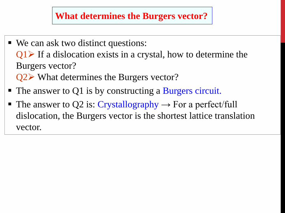
What determines the Burgers vector?
We can ask two distinct questions: Q1 If a dislocation exists in a crystal, how to determine the Burgers vector? Q2 What determines the Burgers vector? The answer to Q1 is by constructing a Burgers circuit. The answer to Q2 is: Crystallography → For a perfect/full
dislocation, the Burgers vector is the shortest lattice translation vector.

In a cubic crystal, a dislocation line of mixed character lies along the [112] direction and the Burgers vector = ½[110]. What is the edge and screw components of the Burgers vector. Which is the slip plane.
t 1 = [112]2 2
1b = [110]2
t = [111]⊥
(110)
t 1 = [112]2 2
1b = [110]2
t = [111]⊥
(110)

(on [110])
(on [112])

In a CCP crystal, is the dislocation reaction shown below feasible energetically? What is the significance of the vectors on the RHS of the reaction?
This is of the form b1 → b2 + b3 The dislocation reaction is feasible if:
As the energy of a dislocation (per unit length of the dislocation line) is proportional to b2
⇒ the dislocation reaction is feasible (i.e., the full dislocation can lower its energy by splitting into partials)
21 2116
b = 31 1216
b =
11 1102
b =
AB
C
(111)
21 2116
b = 31 1216
b =
11 1102
b =
AB
C
(111)
The vectors on the RHS lie on the (111) close packed plane in a CCP crystal and they connect B to C sites and C to B sites, respectively. Equivalent vectors (belonging to the same family) are shown in the figure on the right.
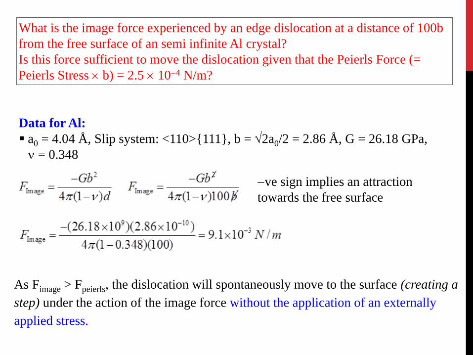
What is the image force experienced by an edge dislocation at a distance of 100b from the free surface of an semi infinite Al crystal? Is this force sufficient to move the dislocation given that the Peierls Force (= Peierls Stress × b) = 2.5 × 10⁻⁴ N/m?
Data for Al: a0 = 4.04 Å, Slip system: <110>{111}, b = √2a0/2 = 2.86 Å, G = 26.18 GPa,
ν = 0.348
−ve sign implies an attraction towards the free surface
As Fimage > Fpeierls, the dislocation will spontaneously move to the surface (creating a step) under the action of the image force without the application of an externally applied stress.


![Nucleation and propagation of dislocations near a ...engineering.snu.ac.kr/pdf/2001-2002(32)/2001_SCS... · prismatic dislocation loops [2-4), dislocation climb sources [5] and dislocation](https://img.dokumen.tips/doc/110x75/5f04810a7e708231d40e4c01/nucleation-and-propagation-of-dislocations-near-a-322001scs-prismatic.jpg)