Embed Size (px)
Citation preview

Introduction to Computer Networks
IEEE 802.3 Ethernet
All rights reserved. No part of this publication and file may be reproduced, stored in a retrieval system, or transmitted in any form or by any means, electronic, mechanical, photocopying, recording or otherwise, without prior written permission of Professor Nen-Fu Huang (E-mail: [email protected]).

Ethernet - 2
Outline
Introduction
Ethernet Topologies
Ethernet Frame Format
Ethernet MAC Protocol -- CSMA/CD
802.3 Ethernet Standards

Ethernet - 3
Ethernet
Most successful local area networking technology of last 30 years.
First widely used LAN technology
kept up with speed race: 10 Mbps – 100 Gbps
Metcalfe’s Ethernet sketch

Ethernet - 4
Ethernet
Developed in the mid-1970s by researchers at the Xerox Palo Alto Research Centers (PARC).
DEC and Intel joined Xerox to define a 10-Mbps Ethernet standard in 1978.
This standard formed the basis for IEEE standard 802.3
More recently 802.3 has been extended to include
100-Mbps version called Fast Ethernet,
1000-Mbps version called Gigabit Ethernet,
10 Gigabit Ethernet, and also
100 Gigabit Ethernet

Ethernet - 5
Ethernet: Unreliable, Connectionless
Connectionless: No handshaking between sending and receiving NICs
Unreliable: receiving NIC doesn’t send ACKs or NACKs to sending NIC
Ethernet’s MAC protocol: Carrier Sense Multiple Access with Collision Detection (CSMA/CD)

Ethernet - 6
Outline
Introduction
Ethernet Topologies
Ethernet Frame Format
Ethernet MAC Protocol -- CSMA/CD
802.3 Ethernet Standards

Ethernet - 7
Bus Topology
Bus topology popular through mid 90s
all nodes in same collision domain (can collide with each other)
同軸電纜
收發器電纜
終端器
終端器收發器
同軸電纜區段(最長 500 公尺)
(每區段最多接 100 個)
(最長 50 公尺)

Ethernet - 8
Ethernet (10Base5)
An Ethernet segment is implemented on a coaxial cable of up to 500 m.
Hosts connect to an Ethernet segment by tapping into it.
A transceiver (a small device directly attached to the tap) detects when the line is idle and drives signal when the host is transmitting.
The transceiver also receives incoming signal.
The transceiver is connected to an Ethernet adaptor which is plugged into the host. But now most are built in into the computers.
The protocol is implemented on the adaptor.

Ethernet - 9
Ethernet (10Base5)
Ethernet transceiver, adaptor, and terminator
Terminator

Ethernet - 10
Network Configuration Example 1 (Single segment)
同軸電纜
收發器電纜
終端器
終端器收發器
同軸電纜區段(最長 500 公尺)
(每區段最多接 100 個)
(最長 50 公尺)

Ethernet - 11
Cable Signaling (Manchester Encoding)
1 0 1 0 1 1 1 0 0
Preamble DataIdle Idle
... ...
-1.825V
-0.225V0V
1 0 1 0 1 1 1 0 0
Preamble DataIdle Idle
... ...
-0.7V0V
+0.7V
100ns 50ns
Coaxial Cable
Transceiver Cable
Each bit has a transition
Allows clocks in sending and receiving nodes to synchronize to each other

Ethernet - 12
Ethernet (10Base5)
Multiple Ethernet segments can be joined together by repeaters.
A repeater is a device that forwards digital signals.
No more than four repeaters may be positioned between any pair of hosts.
An Ethernet has a total reach of only 2500 m.

Ethernet - 13
Network Configuration Example 2 (Two segments)
第一段同軸電纜
同軸電纜區段(最長 500 公尺)
第二段同軸電纜
同軸電纜區段(最長 500 公尺)
收發器電纜(最長 50 公尺)
Repeater

Ethernet - 14
Network Configuration Example 3 (Five segments, maximum)
半訊號增益器間電纜
(最長 1000 公尺)
區段 4
區段 1
區段 2
區段 3
區段 5
1
2
3
4
5
6
Repeater
半訊號增益器

Ethernet - 15
Ethernet (10Base2)
New Technologies in Ethernet
Instead of using coax cable, an Ethernet can be constructed from a thinner cable known as 10Base2(the original was 10Base5)
10 means the network operates at 10 Mbps
Base means the cable is used in a baseband system
2 means that a given segment can be no longer than 200 m

Ethernet - 16
Ethernet (10BaseT)
New Technologies in Ethernet
Another cable technology is 10BaseT
T stands for twisted pair
Limited to 100 m in length
With 10BaseT, the common configuration is to have several point to point segments coming out of a multiway repeater, called Hub

Ethernet - 17
Ethernet
Ethernet Hub
HUB 1 HUB 2

Ethernet - 18
Star Topology
Today: Star topology prevails
active switch in center
each “spoke” runs a (separate) Ethernet protocol (nodes do not collide with each other)
Switch
Star topology

Ethernet - 19
Ethernet-Switch
To speed up the transmission rate of Ethernet Hub without changing the interface cards on stations.
Ether-Switch Architecture
Each Ethernet port can have a transmission simultaneously.

Ethernet - 20
Ethernet Switch ASIC example
Acute Leo AQ6628 24+4 Ethernet Switch ASIC

Ethernet - 21
Outline
Introduction
Ethernet Topologies
Ethernet Frame Format
Ethernet MAC Protocol -- CSMA/CD
802.3 Ethernet Standards

Ethernet - 22
Ethernet Frame Format
Frame format
Preamble (64bits): allows the receiver to synchronize with the signal (sequence of alternating 0s and 1s).
Source and Destination MAC Addresses (48bits each).
Packet type (16bits): acts as demux key to identify the higher level protocol.
Data (up to 1500 bytes)
Minimally a frame must contain at least 46 bytes of data.
Frame must be long enough to detect collision.
FCS: CRC (32bit)
Preamble SFD DA SA Type LLC PAD FCS
7 1 6 6 2 4 bytes

Ethernet - 23
Ethernet Frame Format
Preamble SFD DA SA TYPE LLC PAD FCS
7 1 6 6 2 4 位元組
Preamble: (101010...1010) for Synchronization SFD: Start Frame Delimiter (10101011) DA: Destination MAC Address SA: Source MAC Address Packet type (16bits): acts as demux key to identify the higher
level protocol. LLC-Frame: Up to 1500 bytes PAD: Padding when LLC-Frame < 46 bytes FCS: Frame Check Sequence (CRC-32) MAC-frame size -- from DA to FCS
Min 64 bytes to distinguish from collision Max 1518 bytes to prevent dominating bandwidth

Ethernet - 24
Ethernet Addresses
Each host on an Ethernet (in fact, every Ethernet host in the world) has a unique Ethernet Address.
The address belongs to the adaptor, not the host.
It is usually burnt into ROM.
Ethernet addresses are typically printed in a human readable format
As a sequence of six numbers separated by colons.
Each number corresponds to 1 byte of the 6 byte address and is given by a pair of hexadecimal digits, one for each of the 4-bit nibbles in the byte
Leading 0s are dropped.
For example, 8:0:2b:e4:b1:2 is
00001000 00000000 00101011 11100100 10110001 00000010
Ethernet - 25
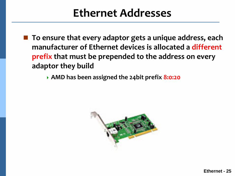
Ethernet Addresses
To ensure that every adaptor gets a unique address, each manufacturer of Ethernet devices is allocated a different prefix that must be prepended to the address on every adaptor they build
AMD has been assigned the 24bit prefix 8:0:20

Ethernet - 26
Ethernet Addresses
Each frame transmitted on an Ethernet is received by every adaptor connected to that Ethernet.
Each adaptor recognizes those frames addressed to its address and passes only those frames on to the host.
In addition to unicast address, an Ethernet address consisting of all 1s is treated as a broadcast address.
All adaptors pass frames addressed to the broadcast address up to the host.
Similarly, an address that has the first bit set to 1 but is not the broadcast address is called a multicast address.
A given host can program its adaptor to accept some set of multicast addresses.

Ethernet - 27
Ethernet Addresses
To summarize, an Ethernet adaptor receives all frames and accepts
Frames addressed to its own address
Frames addressed to the broadcast address
Frames addressed to a multicast address if it has been instructed

Ethernet - 28
Outline
Introduction
Ethernet Topologies
Ethernet Frame Format
Ethernet MAC Protocol -- CSMA/CD
802.3 Ethernet Standards

Ethernet - 29
Ethernet MAC protocol
Any signal placed on the Ethernet by a host is broadcast over the entire network
Signal is propagated in both directions.
Repeaters forward the signal on all outgoing segments.
Terminators attached to the end of each segment absorb the signal.
同軸電纜
收發器電纜
終端器
終端器收發器

Ethernet - 30
CSMA (Carrier Sense Multiple Access)
CSMA: listen before transmit:
If channel sensed idle: transmit entire frame
If channel sensed busy, defer transmission

Ethernet - 31
CSMA collisions
collisions can still occur:propagation delay means two nodes may not heareach other’s transmission
collision:entire packet transmission time wasted

Ethernet - 32
CSMA/CD (Collision Detection)
CSMA/CD: carrier sensing, deferral as in CSMA
collisions detected within short time
colliding transmissions aborted, reducing channel wastage
Collision detection:
Measure signal strengths, compare transmitted, received signals

Ethernet - 33
CSMA/CD collision detection

Ethernet - 34
CSMA/CD
Carrier Sense Multiple Access with Collision Detection (CSMA/CD).
A set of nodes send and receive frames over a shared link.
Carrier sense means that all nodes can distinguish between an idle and a busy link.
Collision detection means that a node listens as it transmits and can therefore detect when a frame it is transmitting has collided with a frame transmitted by another node.

Ethernet - 35
CSMA/CD
When the adaptor has a frame to send and the line is idle, it transmits the frame immediately.
When the adaptor has a frame to send and the line is busy, it waits for the line to go idle and then transmits immediately.
The Ethernet is said to be 1-persistent protocol because an adaptor with a frame to send transmits with probability 1 whenever a busy line goes idle.

Ethernet - 36
CSMA/CD
Since there is no centralized control it is possible for two (or more) adaptors to begin transmitting at the same time,
Either because both found the line to be idle,
Or, both had been waiting for a busy line to become idle.
When this happens, the two (or more) frames are said to be collide on the network.

Ethernet - 37
CSMA/CD
Since Ethernet supports collision detection, each sender is able to determine that a collision is in progress.
At the moment an adaptor detects that its frame is colliding with another, it first makes sure to transmit a 32-bit jamming sequence and then stops transmission.
Thus, a transmitter will minimally send 96 bits in the case of collision
64-bit preamble + 32-bit jamming sequence

Ethernet - 38
CSMA/CD
One way that an adaptor will send only 96 bits (called a runt frame) is if the two hosts are close to each other.
In case the two hosts are farther apart, they would have had to transmit longer, and thus send more bits, before detecting the collision.

Ethernet - 39
Collision Window
The worst case scenario happens when the two hosts are at opposite ends of the Ethernet.
To know for sure that the frame its just sent did not collide with another frame, the transmitter may need to send as many as 512 bits.
Every Ethernet frame must be at least 512 bits (64 bytes) long.
14 bytes of header + 46 bytes of data + 4 bytes of CRC
Preamble SFD DA SA Type LLC PAD FCS
7 1 6 6 2 4 bytes

Ethernet - 40
Collision Window
Why 512 bits (64 bytes) ?
Why is its length limited to 2500 m?
Collision Window = round-trip delay (2a)
The farther apart two nodes are, the longer it takes for a frame sent by one to reach the other, and the network is vulnerable to collision during this time

Ethernet - 41
Collision Detection Window for CSMA/CD (=2a)
BA
Propagation delay = a
t
BA
t+a-e
BA
t+a
BA
t+2a-e
衝撞
A開始傳送
B開始傳送
B偵測出衝撞
A偵測出衝撞

Ethernet - 42
Collision Window
A begins transmitting a frame at time t
a denotes the one link latency
The first bit of A’s frame arrives at B at time t + a
Suppose an instant before host A’s frame arrives, host B begins to transmit its own frame
B’s frame will immediately collide with A’s frame and this collision will be detected by host B
Host B will send the 32-bit jamming sequence
Host A will not know that the collision occurred until B’s frame reaches it, which will happen at t + 2a
Host A must continue to transmit until this time in order to detect the collision Host A must transmit for 2a to be sure that it detects all possible
collisions

Ethernet - 43
Collision Window
Consider that a maximally configured Ethernet is 2500 m long, and there may be up to four repeaters between any two hosts, the round trip delay has been determined to be 51.2 s
Which on 10 Mbps Ethernet corresponds to 512 bits
10 Mbps x 51.2 s = 512 bits
The other way to look at this situation,
We need to limit the Ethernet’s maximum latency to a fairly small value (51.2 s) for the access algorithm to work
Hence the maximum length for the Ethernet is on the order of 2500 m.

Ethernet - 44
Exponential Backoff Algorithm
Once an adaptor has detected a collision, and stopped its transmission, it waits a certain amount of time and tries again.
Each time the adaptor tries to transmit but fails, it doubles the amount of time it waits before trying again.
This strategy of doubling the delay interval between each retransmission attempt is known as Exponential Backoff.

Ethernet - 45
Exponential Backoff Algorithm
The adaptor first delays either 0 or 51.2 s, selected at random.
If this effort fails, it then waits 0, 51.2, 102.4, 153.6 s (selected randomly) before trying again;
This is k * 51.2 for k = 0, 1, 2, 3
After the third collision, it waits k * 51.2 for k = 0…23 – 1 (again selected at random).
In general, the algorithm randomly selects a kbetween 0 and 2n – 1 and waits for k * 51.2 s, where n is the number of collisions experienced so far.

Ethernet - 46
CSMA/CD Protocol
Carrier Sense before transmission
Carrier Sense while transmission
Collision: Two or more stations transmitting simultaneously
Backoff: Random delay after collision
Deference: Defers transmission if channel is sensed busy
Collision Window (Slot time): Round-trip propagation delay time plus some carrier sense time. In IEEE 802.3, this value is defined to be 51.2 us.

Ethernet - 47
CSMA/CD Collision Handling
Collision Signal is generated by Physical layer.
Jam signal (collision enforcement): To make sure that all stations involved in the collision will detect collision. A pattern of 32 bits.
Collision backoff and retransmission method (Truncated Binary Exponential BackoffAlgorithm, BEBA):
n : number of collisions experienced (n <= 16)
k : Min (n,10) -- Truncation
r : Random delay time (unit: slot time), 0 <= r < 2k

Ethernet - 48
CSMA/CD Collision Handling
Slot time = 51.2 us.
Disadvantage of BEBA:
Last-in-First-out effect: Stations with no or few collisions will have a better chance to transmit before stations that have waited longer.

Ethernet - 49
Ethernet Performance
Ethernets work best under lightly loaded conditions.
Under heavy loads, too much of the network’s capacity is wasted by collisions.
Loading
Th
rou
gh
pu
t

Ethernet - 50
Outline
Introduction
Ethernet Topologies
Ethernet Frame Format
Ethernet MAC Protocol -- CSMA/CD
802.3 Ethernet Standards

Ethernet - 51
802.3 Ethernet Standards: Link & Physical Layers
Many different Ethernet standards
common MAC protocol (CSMA/CD) and frame format
different speeds: 2 Mbps, 10 Mbps, 100 Mbps, 1Gbps, 10Gbps, 100Gbps
different physical layer media: fiber, cable
applicationtransportnetwork
linkphysical
MAC protocoland frame format
100BASE-TX
100BASE-T4
100BASE-FX100BASE-T2
100BASE-SX 100BASE-BX
fiber physical layercopper (twister pair) physical layer

Ethernet - 52
Summary
MAC Protocol -- CSMA/CD
Connection less, unreliable transmission
Topology from Bus to Star (switches)
Half-duplex transmission in Bus topology
Work best under lightly loaded conditions
Too much collision under heavy load
Full-duplex transmission in Switch topology (point-to-point)
No more collisions !!
Excellent performance (wired speed)